rule 1111 nitrogen oxides emissions compliance testing …
TRANSCRIPT
SOUTH COAST AIR QUALITY MANAGEMENT DISTRICT
PROTOCOL
RULE 1111 NITROGEN OXIDES EMISSIONS COMPLIANCE TESTING FOR
NATURAL GAS-FIRED, FAN-TYPE CENTRAL FURNACES
JULY 12, 1994
SOURCE TESTING AND ENGINEERING BRANCH
APPLIED SCIENCE AND TECHNOLOGY

SOUTH COAST AIR QUALITY MANAGEMENT DISTRICT
PROTOCOL
RULE 1111 NITROGEN OXIDES EMISSIONS COMPLIANCE TESTING FOR
NATURAL GAS-FIRED, FAN-TYPE CENTRAL FURNACES
JULY 12, 1994
SOURCE TESTING AND ENGINEERING BRANCH
APPLIED SCIENCE AND TECHNOLOGY
TABLE OF CONTENTS
PAGE
-i-
TABLE OF CONTENTS.................................. ......... i
1.0 OVERVIEW AND APPLICABILITY..................... ......... 1
2.0 ENVIRONMENTAL CRITERIA......................... ......... 3
3.0 DEFINITIONS.................................... ......... 4
3.1 INDEPENDENT TESTING LABORATORY................. ..... 4
3.2 NATURAL GAS-FIRED, FAN-TYPE CENTRAL FURNACE.... ..... 4
3.3 ANNUAL FUEL UTILIZATION EFFICIENCY (AFUE)...... ..... 4
4.0 TEST CONDITIONS................................ ......... 5
4.1 AMBIENT AIR TEMPERATURE........................ ..... 5
4.2 NATURAL GAS PRESSURE........................... ..... 5
4.3 INSTALLATION REQUIREMENTS...................... ..... 5
5.0 INSTRUMENTATION................................ ......... 6
5.1 PRESSURE MEASUREMENT........................... ..... 6
5.2 TEMPERATURE MEASUREMENTS....................... ..... 6
5.3 BAROMETRIC PRESSURE............................ ..... 6
5.4 NATURAL GAS FLOW............................... ..... 7
5.5 TIME........................................... ..... 7
5.6 FLUE GAS ANALYSIS.............................. ..... 7
5.6.1 NOx CONCENTRATION............................ . 7
5.6.2 CO CONCENTRATION............................. . 7
5.6.3 CO 2 CONCENTRATION ............................. 7
5.6.4 SAMPLE CONDITIONING SYSTEM................... . 8
5.6.4.1 Sample Probe............................ 8
5.6.4.1.1 Integrating Sample Probes......... 8
5.6.4.1.2 Open Ended Sample Probes.......... 8
5.6.4.2 Sample Lines............................ 8
TABLE OF CONTENTS
PAGE
-ii-
5.6.4.3 Moisture Removal System................. 9
5.6.4.3.1 Permeation-Type Dryers............ 9
5.6.4.3.2 Refrigerated Condenser/Separator.. 9
5.6.4.4 Sample Pump............................. 9
5.6.4.5 Flow Indicators......................... 9
5.6.4.6 Pressure Indicators.................... 10
5.6.4.7 Sample Vent............................ 10
5.7 NATURAL GAS COMPOSITION........................ .... 10
6.0 ANALYTICAL METHODS............................. ........ 11
6.1 START UP....................................... .... 11
6.1.1 ANALYZERS.................................... 11
6.1.2 SAMPLE CONDITIONING SYSTEM................... 11
6.2 CALIBRATION AND PERFORMANCE TESTING............ .... 11
6.2.1 ANALYZER CALIBRATION......................... 11
6.2.2 SAMPLING SYSTEM BIAS TEST.................... 11
6.2.3 RESPONSE TIME................................ 12
6.2.4 NO 2 TO NO CONVERSION EFFICIENCY .............. 12
6.3 ANALYSIS....................................... .... 13
6.3.1 SAMPLE POINT................................. 13
6.3.1.1 Appliances with Vents Less Than 12 Inch
Diameter............................... 13
6.3.1.2 Appliances With Vents 12 Inch Diameter or
Greater................................ 13
6.3.2 SAMPLING PERIOD.............................. 13
6.3.2.1 Integrating Sample Probes.............. 13
6.3.2.2 Sample Traverses....................... 14
TABLE OF CONTENTS
PAGE
-iii-
6.3.3 DATA RECORDING............................... 14
7.0 INSTALLATION................................... ........ 15
7.1 Furnace Mounting............................... 15
7.2 Fuel Consumption............................... 15
7.3 Inlet/ Ambient Temperature..................... 15
7.4 Outlet Air Temperature Measurements............ 15
7.5 Vent Requirements.............................. 15
7.6 Natural Gas Sample............................. 16
8.0 TEST PROCEDURE................................. ........ 17
8.1 Power Input.................................... .... 17
8.2 Static Pressure and Air Flow Adjustments....... .... 17
8.3 Emission Testing............................... .... 17
9.0 CALCULATIONS................................... ........ 20
9.1 CARBON NUMBER.................................. .... 20
9.2 HEATING VALUE.................................. .... 21
9.3 CO 2 FOR STOICHIOMETRIC COMBUSTION .................. 22
9.4 EMISSION OF NOx................................ .... 22
10.0 REPORT........................................ ........ 24
10.1 TEST RESULTS.................................. .... 24
10.2 FORMS USED FOR PERFORMING THE CALCULATIONS.... .... 24
10.3 REPORT FORMAT................................. .... 25
FIGURES AND DATA FORMS............................. ........ 27
APPENDIX A
-1-
RULE 1111 NITROGEN OXIDES EMISSIONS COMPLIANCE TESTING FOR NATURAL GAS-FIRED, FAN-TYPE CENTRAL FURNACES
PROTOCOL
1.0 OVERVIEW AND APPLICABILITY
The South Coast Air Quality Management District ado pted Rule
1111, Control of Nitrogen Oxides from Natural Gas-F ired, Fan-Type
Central Furnaces on July 8, 1983. This rule impose s an emission
limit of 40 nanograms of NOx (calculated as NO 2) per joule of
useful heat delivered to the heated space. Natural gas-fired,
fan-type central furnaces (furnaces) require testin g to certify
compliance with the 40 nanograms of NOx per joule e mission limit
before they can be supplied, offered for sale or so ld within the
jurisdiction of the South Coast Air Quality Managem ent District.
This protocol has been developed to ensure standard ization of
compliance certification test procedures including the use of:
specified test conditions, required test methods, s pecifications
for test equipment, data collection/reporting and q uality
assurance requirements.
An independent testing laboratory, approved by the South Coast
Air Quality Management District, shall conduct the testing and
prepare a report of findings, including all raw dat a
sheets/charts and laboratory analytical data. This report and a
request for product certification must be submitted to the
Executive Officer. The testing must demonstrate to the
satisfaction of the Executive Officer that emission s from the
-2-
operation of a furnace meets the requirements of Ru le 1111 before
product compliance certification is granted.
When a furnace does not fall within the testing gui delines of
this protocol, written modification to the protocol must be
submitted for review, prior to written approval by the Executive
Officer, along with supporting documents which demo nstrate
equivalency to the existing protocol.
-3-
2.0 ENVIRONMENTAL CRITERIA
Testing shall be conducted indoors with the ambient air
temperature of the test room maintained between 65 oF and 85 oF at
all times during the test. The ambient air tempera ture during
these tests shall not vary more than + 7 oF from the average
ambient air temperature determined as the arithmeti c average of
the air temperatures measured periodically at inter vals no
greater than 15 minutes throughout the duration of the test.
The ambient temperature shall be monitored and reco rded before,
during, and after the tests in accordance with Sect ion 7.3 of
this protocol.
The relative humidity shall be between 20% and 65% during the
test. It shall be recorded before and after the te st.
The barometric pressure shall be monitored and reco rded before
and after each test.
-4-
3.0 DEFINITIONS
For the purposes of this test protocol, the followi ng definitions
shall apply:
3.1 INDEPENDENT TESTING LABORATORY
A testing laboratory that meets the requirements o f
South Coast Air Quality Management District's Rule
304(k), and is approved by the SCAQMD to conduct te sting
under this protocol.
3.2 NATURAL GAS-FIRED, FAN-TYPE CENTRAL FURNACE
A self-contained space heater providing for circul ation
of heated air at pressures other than atmospheric
through ducts more than 10 inches in length that ha ve:
A) an input rate of less than 175,000 BTU/hr; or
B) for combination heating and cooling units,
a cooling rate of less than 65,000 BTU/hr.
3.3 ANNUAL FUEL UTILIZATION EFFICIENCY (AFUE)
Defined in Section 4.6 of Code of Federal Regulati ons,
Title 10, Part 430, Subpart B, Appendix N.
-5-
4.0 TEST CONDITIONS
4.1 AMBIENT AIR TEMPERATURE
The ambient air temperature shall be controlled to a
value between 65 oF and 85 oF on a continuous basis.
4.2 NATURAL GAS PRESSURE
Maintain the supply pressure in accordance with th e
manufacturer's specifications. If the supply press ure
is not specified, maintain a supply pressure of 7-1 0
inches of water column. Use natural gas with a dry or
higher heating value of 1040 + 25 BTU per standard cubic
foot (14.73 psia and 60 oF). Higher heating value shall
be measured according to procedures described in
Section 5.7.
4.3 INSTALLATION REQUIREMENTS
Tests shall be performed with the furnace and
instrumentation installed in accordance with Sectio n 7.
-6-
5.0 INSTRUMENTATION
All instrumentation within this section and pertain ing to this
protocol shall be calibrated as a minimum within th e requirements
set forth in SCAQMD Source Test Methods Chapter III ,
Calibrations.
5.1 PRESSURE MEASUREMENT
Pressure measurement instruments shall have an err or no
greater than the following values:
Measurement Accuracy Precision
Gas Pressure + 0.1" of + 0.05" of water column water column
Atmospheric + 0.1" of + 0.05" of Pressure Hg column Hg column
5.2 TEMPERATURE MEASUREMENTS
Temperature measuring instruments shall have an er ror no
greater than the following values:
Accuracy Precision
+ 1 oF + 1 oF
The time constant of instruments measuring inlet a nd
outlet water temperatures shall be 5 seconds or les s.
5.3 BAROMETRIC PRESSURE
Use a mercury, aneroid, or other barometer capable of
measuring atmospheric pressure to within 0.1 in. Hg .
-7-
5.4 NATURAL GAS FLOW
The quantity of fuel used by the furnace shall be
measured in cubic feet with dry gas meter and assoc iated
readout device that is accurate within + 1% of the
reading. The dry gas meter reading shall be correc ted
for gas pressure and temperature.
5.5 TIME
The elapsed time measurement shall be measured wit h an
instrument that is accurate within + 0.5 seconds per
hour.
5.6 FLUE GAS ANALYSIS
5.6.1 NOx CONCENTRATION A chemiluminescence NOx Analyzer
shall be employed to measure NOx in flue gas.
Performance specifications of the analyzer shall be in
accordance with SCAQMD Method 100.1 (Appendix A).
5.6.2 CO CONCENTRATION A non-dispersive infrared analyzer
shall be employed to measure CO in flue gas.
Performance specifications of the analyzer shall be in
accordance with SCAQMD Method 100.1 (Appendix A).
5.6.3 CO 2 CONCENTRATION A non-dispersive infrared analyzer
shall be employed to measure CO 2 in flue gas.
Performance specifications of the analyzer shall be in
accordance with SCAQMD Method 100.1 (Appendix A).
-8-
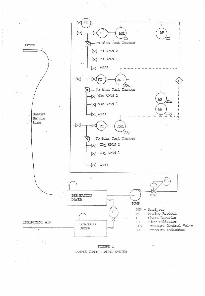
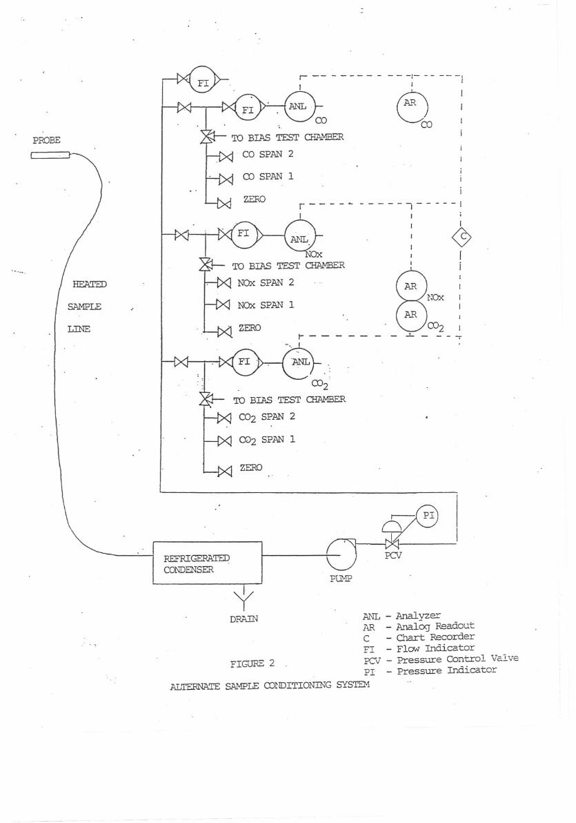
5.6.4 SAMPLE CONDITIONING SYSTEM The NOx, CO, and CO 2
analyzers shall sample flue gas delivered by a sing le
sample conditioning system. The gases shall be mea sured
simultaneously after undergoing identical sample
conditioning. Figures 1 and 2 show acceptable samp le
conditioning systems. Additional components may be
added at the user's discretion. However, deviation s
from the basic design must be approved by the Execu tive
Officer.
5.6.4.1 Sample Probe
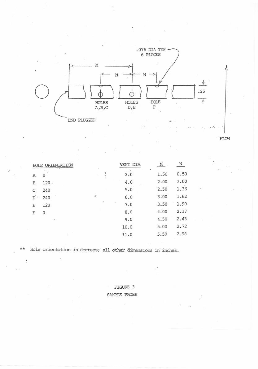
5.6.4.1.1 Integrating Sample Probes Integrating sample probes
may be used with vents less than 12 inches in diame ter.
Figure 3 shows an acceptable hole layout for an
integrating sample probe. The probe shall be of 31 6
stainless steel construction.
5.6.4.1.2 Open Ended Sample Probes Open ended sample probes
shall be used to sample vents 12 inches in diameter and
larger.
5.6.4.2 Sample Lines The sample line shall be of Teflon
construction. It shall be electrically heated. Th e
allowable temperature range is 175 oF - 300 oF. The use
of self-limiting heated sample line is permitted.
-9-
5.6.4.3 Moisture Removal System The moisture removal system
shall be comprised of a permeation-type dryer, or a
refrigerated condenser/separator, or a combination of
the two moisture removal methods. The dew point of the
dry gas shall be less than 35 oF.
5.6.4.3.1 Permeation-Type Dryers A Permapure permeation-type
dryer may be employed to dry the sample gas. The a ir
to the dryer shall be dried with a heat-less dryer,
which includes a colored moisture indicator.
5.6.4.3.2 Refrigerated Condenser/Separator A refrigerated
condenser/separator designed to minimize contact
between the condensate and the sample gas may be us ed
to dry the sample gas. An example would be a knock -out
system consisting of a series of empty bubblers
immersed in an ice bath.
5.6.4.4 Sample Pump The sample pump shall be a diaphragm type.
The diaphragm shall be Viton A; other wetted parts of
the pump shall be 316 stainless steel. An equivale nt
type of sample pump may be used upon approval by th e
Executive Officer.
5.6.4.5 Flow Indicators Because the flow indicators in the
sample conditioning system are for the operators
-10-
convenience, they do not have to be calibrated. W ater
shall not be allowed to collect in the indicator tu bes.
5.6.4.6 Pressure Indicators Because the pressure indicators in
the sample conditioning system are for the operator s
convenience, they do not have to be calibrated.
5.6.4.7 Sample Vent The analyzers shall have an unrestricted
atmospheric sample vent.
5.7 NATURAL GAS COMPOSITION
Heating value or gas composition of the fuel must be
measured. If the heating value is measured, the
accuracy of the measurement device shall be + 1% of
full scale. The precision of the device shall be
+ 2 Btu/dscf. Calibration shall be conducted weekly
using the device manufacturer's directions.
If the composition of the fuel is measured, it sha ll be
measured with a gas chromatograph having a TC detec tor.
Ethane, Propane, C4+, CO 2, and permanent gases will be
measured directly. Methane may be determined by
difference. The reproducibility of the gas
chromatograph shall be + 1% of full scale for each
measured component.
-11-
6.0 ANALYTICAL METHODS
6.1 START UP
6.1.1 ANALYZERS Allow analyzers to warm up according to
manufacturer's instructions. It is recommended tha t the
analyzers be allowed to run overnight before testin g.
6.1.2 SAMPLE CONDITIONING SYSTEM Energize the sample pump and
sample line; allow temperatures and flows to come t o
equilibrium.
6.2 CALIBRATION AND PERFORMANCE TESTING
6.2.1 ANALYZER CALIBRATION Use calibration gases which are
certified according to EPA Traceability Protocol Nu mber
1. CO calibration gases may be certified to an acc uracy
of + 2%. A high span calibration gas shall be selected
such that the emission concentrations will be great er
than 20% and less than 95% of the high span calibra tion
gas value for the duration of each test run. Calib rate
the analyzers according to the manufacturer's
instructions and SCAQMD Method 100.1. It is recomm ended
that the calibration of each analyzer be checked af ter
each test run. A 2% drift invalidates the analysis .
SCAQMD Method 100.1 is included as Appendix A.
6.2.2 SAMPLING SYSTEM BIAS TEST A sampling system bias test
must be performed in accordance with SCAQMD Method 100.1
-12-
before and after each day of testing. The sample b ypass
flowrate shall not be altered during this test.
6.2.3 RESPONSE TIME The system response time test must be
performed before each day of testing if NOx
concentrations are to be determined by multi-point
traverse. The response time test may be performed in
conjunction with the sampling system bias test.
To determine response time, first introduce zero g as
into the sample probe until all readings are stable ;
then switch to high-level calibration gas until a s table
reading is obtained. Record the upscale response t ime,
which is defined as the amount of time for the syst em to
display 95% of the step change. Next re-introduce zero
gas until all readings are stable. Record the down scale
response time. The greater time is the "response t ime"
for the system. An acceptable response time shall be
less than, or equal to 4 minutes.
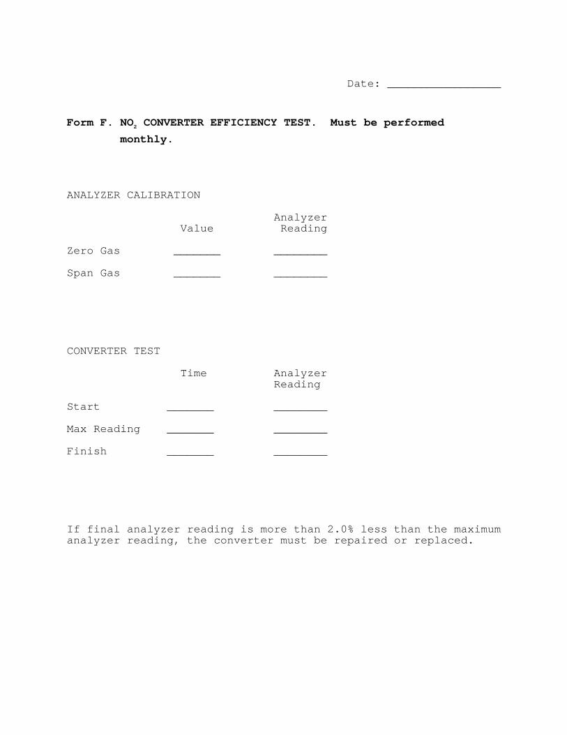
6.2.4 NO 2 TO NO CONVERSION EFFICIENCY The converter
efficiency shall be measured in accordance with EPA
Method 20 at least once a month. If the efficiency does
not meet the requirements listed in Form F, the
converter must be replaced, and all data acquired s ince
the last converter efficiency test shall be conside red
-13-
suspect. The conversion efficiency test is includ ed as
Appendix B.
6.3 ANALYSIS
6.3.1 SAMPLE POINT
6.3.1.1 Appliances with Vents Less Than 12 Inch Dia meter An
integrating sample probe of the proper length is
installed six inches from the upper end of the vent
pipe. The probe must pass through the center of th e
vent and contact the opposite side. A system bias check
and leak check shall be performed after changing
integrating sample probes.
6.3.1.2 Appliances With Vents 12 Inch Diameter or G reater An
open ended sample probe will be used to traverse th e
vent pipe at 1/2 vent diameter below its upper end.
Three traverse points shall be located along the
diameter of the highest expected stratification. T he
traverse points shall be 16.7, 50.0, and 83.3 perce nt of
the diameter. The sample probe will be progressive ly
inserted into the vent pipe along the diameter unti l
each of the three points have been sequentially sam pled.
6.3.2 SAMPLING PERIOD
6.3.2.1 Integrating Sample Probes When sampling with an
integrating sample probe, the analytical system sha ll
-14-
operate continuously during the testing of the
appliance.
6.3.2.2 Sample Traverses When sample traverses are required,
sampling shall begin after the appliance has reache d
steady state as defined in Section 8. Each travers e
point shall be sampled for five minutes.
6.3.3 DATA RECORDING The output of each analyzer shall be
recorded on a strip chart recorder having a minimum
width of ten inches. Alternately, the outputs may be
recorded with a data logger. The sampling rate of the
logger must allow each point to be read at least on ce
every 5 seconds.
-15-
7.0 INSTALLATION
7.1 Furnace Mounting Mounting of the furnace shall be in
accordance with the manufacturer's instructions.
7.2 Fuel Consumption Install one or more instruments to
measure the quantity of natural gas consumed in
accordance with Section 5.4 of this protocol.
7.3 Inlet/ Ambient Temperature The inlet/ ambient air
temperature shall be measured using a single
thermocouple, shielded from direct radiation, at th e
center of the inlet air duct.
7.4 Outlet Air Temperature Measurements An outlet air
sensor shall be located as close to the plenum as i s
practical with no thermocouple being able to see an y
part of the heating surface, or within 6 inches (15 2 mm)
downstream from this location.
7.5 Vent Requirements For furnaces having a vertically
discharging draft hood outlet, a 5 foot vertical ve nt
pipe extension having a diameter equal to the large st
flue collar size of the draft hood shall be connect ed to
the draft hood outlet. For furnaces having a
horizontally discharging draft hood outlet, a 90 o elbow
having diameter equal to the largest collar size of the
-16-
draft hood shall be connected to the draft hood ou tlet
and a vertical 5 feet of length of vent pipe shall be
connected to the elbow. If necessary to prevent
condensation, the vent pipe must be insulated with an
(R) value not less than 4 hr-ft 2- oF/Btu.
7.6 Natural Gas Sample Valving and a tap shall be provided
in the natural gas supply to allow collecting a sam ple
of fuel for composition analysis.
-17-
8.0 TEST PROCEDURE
8.1 Power Input Burners shall be adjusted to their BTU
input rates at + 10% of the stated manifold pressure.
The furnace shall be tested within + 2% of the
manufacturer's specified normal hourly BTU input ra te,
in accordance with Paragraph 2.5.4 of ANSI Z21.47
(1990).
8.2 Static Pressure and Air Flow Adjustments Static
pressure and air throughputs shall be adjusted acco rding
to Section 2.6 of ANSI Z21.47 (1990).
8.3 Emission Testing Allow the heater to operate until
equilibrium conditions are attained. Equilibrium i s
defined by the following conditions during a 15 min ute
interval:
A) Temperature changes in the flue gas of not more
than + 5 oF between readings 15 minutes apart
when the flue gas temperature thermocouple is
located in the center position of the flue;
B) NOx changes in the flue gas of not more than
+ 2 ppm from the mean sampled over the 15 minute
interval;
C) CO 2 changes in the flue gas of not more than
+ 0.25 percent (+ 2500 ppm) from the mean
sampled over the 15 minute interval.
-18-
While establishing the equilibrium conditions abov e, gas
measurements shall be made using an integrating sam pling
probe for vents less than 12 inches in diameter, an d
with an open ended probe located at the center of t he
vent for vent diameters greater than, or equal to
12 inches.
At the start of the test, record the time and gas meter
reading. Do not interrupt the flow to the furnace.
Record the inlet and outlet air temperatures at 60
second intervals throughout the duration of the tes t.
Temperature rise cannot change by more than 5 oF during
the test. Continuously record the NOx, CO, and CO 2
emissions during a five minute test interval. If a n
integrating sampling probe is employed, record the gas
meter reading at the end of sampling. Determine th e
arithmetic mean of CO 2 and NOx concentration measured
during the five minute test period. Record the max imum
CO concentration during the test. Collect a sample of
fuel for composition analysis.
If a sample traverse is required, identify the tra verse
point being sampled on the strip chart recorder and
record the concentration of NOx and CO 2 at each point.
Continuously record the NOx, CO, and CO 2 emissions
during each five minute test interval. When the
traverse is complete, record the gas meter reading.
Determine the arithmetic mean of CO 2 and NOx
-19-
concentration measured during each five minute tes t
interval. Collect a sample of fuel for composition
analysis.
-20-
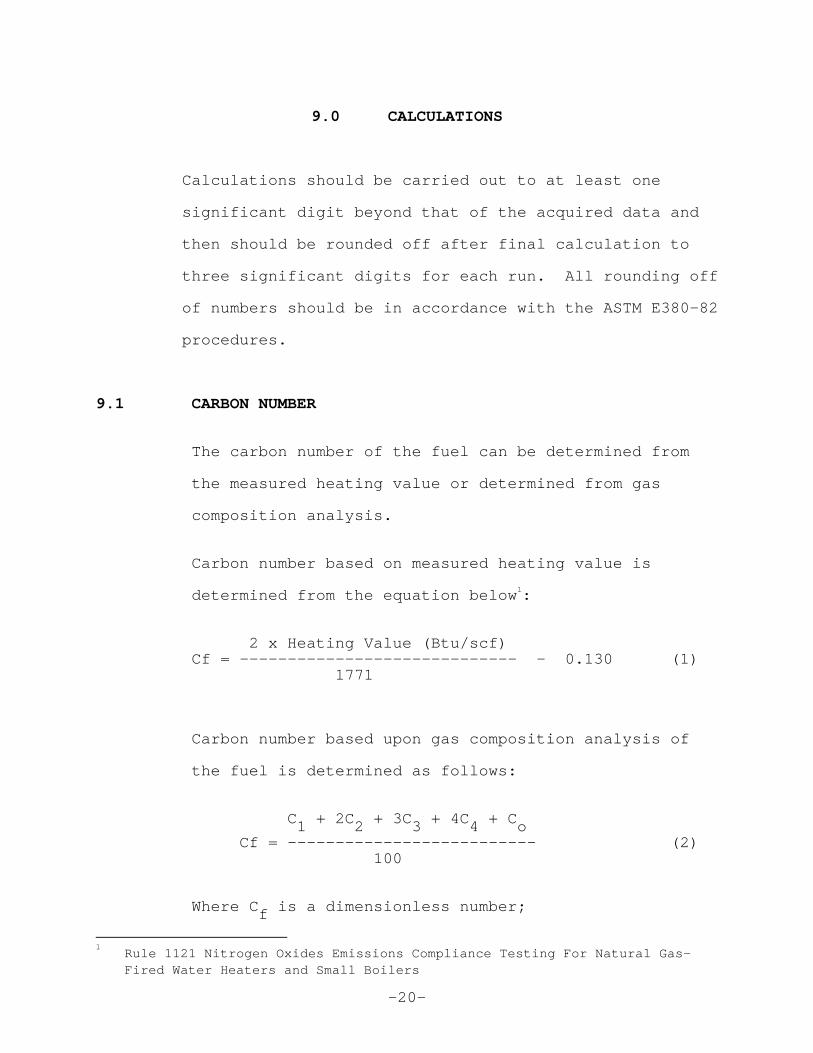
9.0 CALCULATIONS
Calculations should be carried out to at least one
significant digit beyond that of the acquired data and
then should be rounded off after final calculation to
three significant digits for each run. All roundin g off
of numbers should be in accordance with the ASTM E3 80-82
procedures.
9.1 CARBON NUMBER
The carbon number of the fuel can be determined fr om
the measured heating value or determined from gas
composition analysis.
Carbon number based on measured heating value is
determined from the equation below 1:
2 x Heating Value (Btu/scf) Cf = ————————————————————————————— - 0.130 (1) 1771
Carbon number based upon gas composition analysis of
the fuel is determined as follows: C 1 + 2C 2 + 3C 3 + 4C 4 + C o Cf = —————————————————————————— (2) 100 Where C f is a dimensionless number;
1 Rule 1121 Nitrogen Oxides Emissions Compliance Tes ting For Natural Gas-
Fired Water Heaters and Small Boilers
-21-
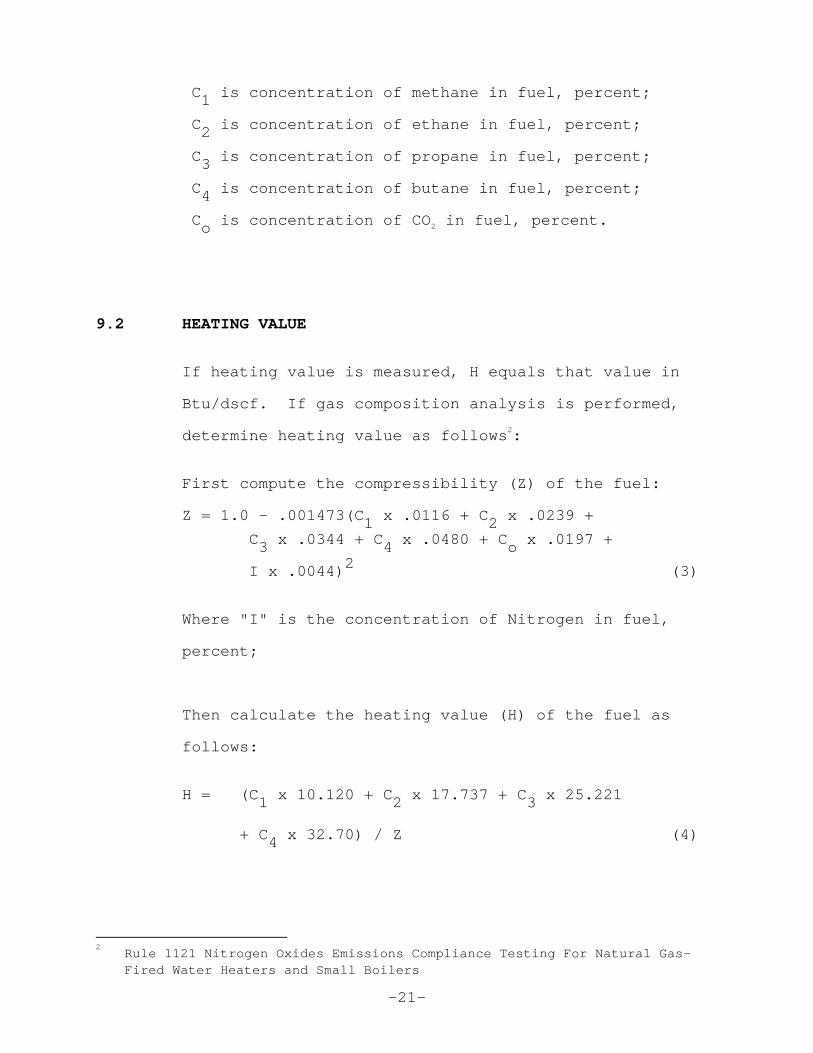
C 1 is concentration of methane in fuel, percent;
C 2 is concentration of ethane in fuel, percent;
C 3 is concentration of propane in fuel, percent;
C 4 is concentration of butane in fuel, percent;
C o is concentration of CO 2 in fuel, percent.
9.2 HEATING VALUE
If heating value is measured, H equals that value in
Btu/dscf. If gas composition analysis is performed ,
determine heating value as follows 2:
First compute the compressibility (Z) of the fuel:
Z = 1.0 - .001473(C 1 x .0116 + C 2 x .0239 +
C 3 x .0344 + C 4 x .0480 + C o x .0197 +
I x .0044) 2 (3)
Where "I" is the concentration of Nitrogen in fuel ,
percent;
Then calculate the heating value (H) of the fuel a s
follows:
H = (C 1 x 10.120 + C 2 x 17.737 + C 3 x 25.221
+ C 4 x 32.70) / Z (4)
2 Rule 1121 Nitrogen Oxides Emissions Compliance Tes ting For Natural Gas-
Fired Water Heaters and Small Boilers
-22-
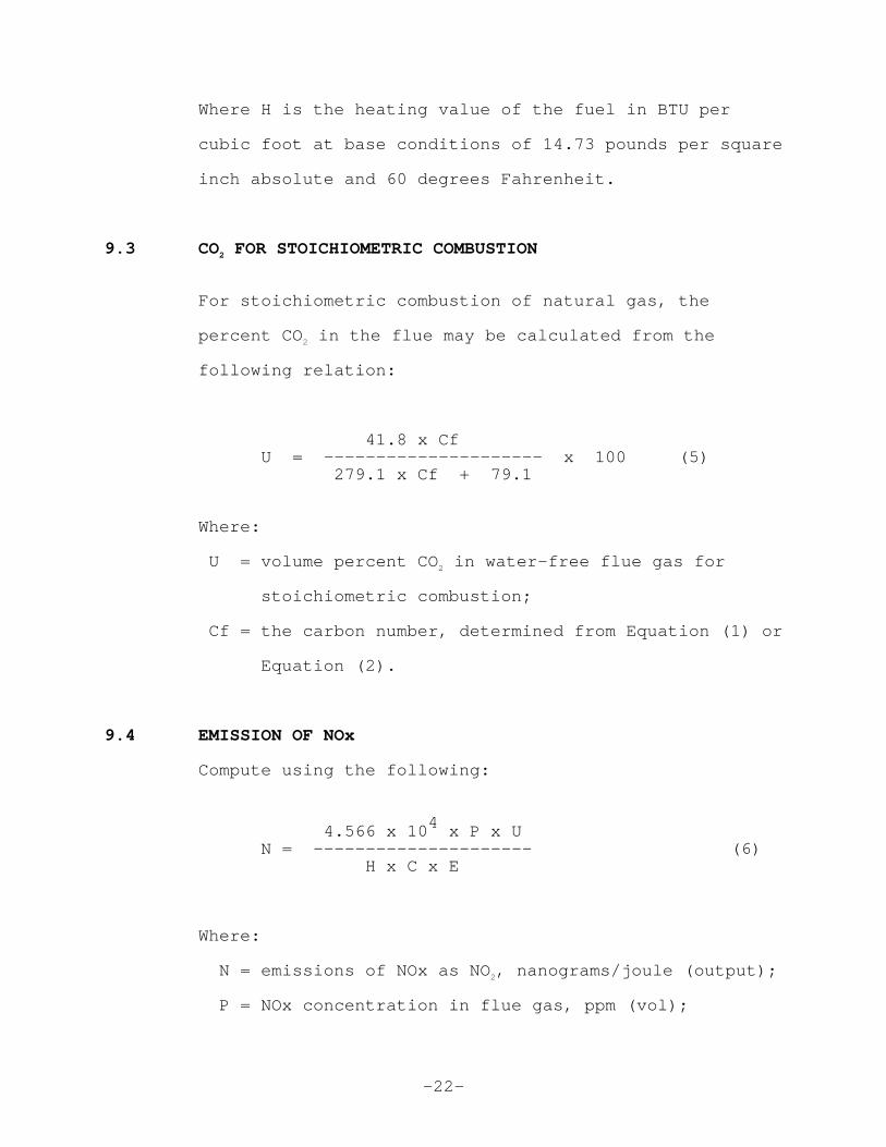
Where H is the heating value of the fuel in BTU pe r
cubic foot at base conditions of 14.73 pounds per s quare
inch absolute and 60 degrees Fahrenheit.
9.3 CO2 FOR STOICHIOMETRIC COMBUSTION
For stoichiometric combustion of natural gas, the
percent CO 2 in the flue may be calculated from the
following relation:
41.8 x Cf U = ————————————————————— x 100 (5) 279.1 x Cf + 79.1
Where:
U = volume percent CO 2 in water-free flue gas for
stoichiometric combustion;
Cf = the carbon number, determined from Equation (1) or
Equation (2).
9.4 EMISSION OF NOx
Compute using the following:
4.566 x 10 4 x P x U N = ————————————————————— (6) H x C x E
Where:
N = emissions of NOx as NO 2, nanograms/joule (output);
P = NOx concentration in flue gas, ppm (vol);
-23-
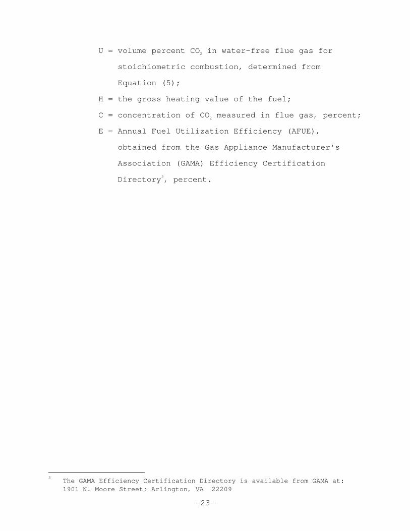
U = volume percent CO 2 in water-free flue gas for
stoichiometric combustion, determined from
Equation (5);
H = the gross heating value of the fuel;
C = concentration of CO 2 measured in flue gas, percent;
E = Annual Fuel Utilization Efficiency (AFUE),
obtained from the Gas Appliance Manufacturer's
Association (GAMA) Efficiency Certification
Directory 3, percent.
3 The GAMA Efficiency Certification Directory is ava ilable from GAMA at:
1901 N. Moore Street; Arlington, VA 22209
-24-
10.0 REPORT
10.1 TEST RESULTS
The following forms may be used in reporting test
results:
Form A. General Information
Form B. Appliances with vents less than 12 inches in
diameter.
Form C. Appliances with vents 12 inches in diamete r and
larger.
Form D. Gas composition analysis and average carbo n
number
Form E. Daily calibration check and sampling syste m bias
test
Form F. Monthly NO 2 converter efficiency test
10.2 FORMS USED FOR PERFORMING THE CALCULATIONS
Form G. Correction of gas meter reading and
determination of firing rate.
Form H. Calculation of NOx Emissions
-25-
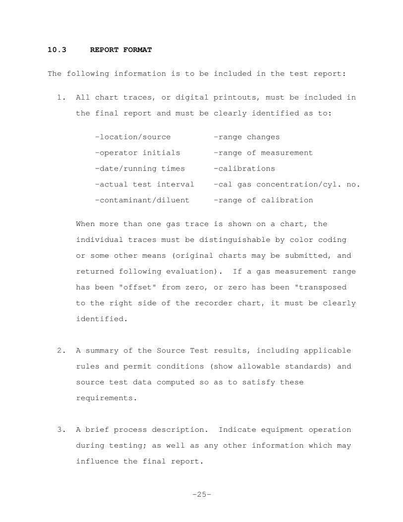
10.3 REPORT FORMAT
The following information is to be included in the test report:
1. All chart traces, or digital printouts, must be included in
the final report and must be clearly identified as to:
-location/source -range changes
-operator initials -range of measurement
-date/running times -calibrations
-actual test interval -cal gas concentration/cyl. no.
-contaminant/diluent -range of calibration
When more than one gas trace is shown on a chart, the
individual traces must be distinguishable by color coding
or some other means (original charts may be submitt ed, and
returned following evaluation). If a gas measureme nt range
has been "offset" from zero, or zero has been "tran sposed
to the right side of the recorder chart, it must be clearly
identified.
2. A summary of the Source Test results, includi ng applicable
rules and permit conditions (show allowable standar ds) and
source test data computed so as to satisfy these
requirements.
3. A brief process description. Indicate equipm ent operation
during testing; as well as any other information wh ich may
influence the final report.
-26-
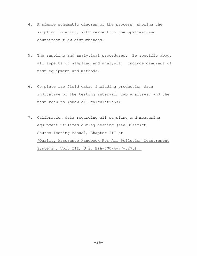
4. A simple schematic diagram of the process, sh owing the
sampling location, with respect to the upstream and
downstream flow disturbances.
5. The sampling and analytical procedures. Be s pecific about
all aspects of sampling and analysis. Include diag rams of
test equipment and methods.
6. Complete raw field data, including production data
indicative of the testing interval, lab analyses, a nd the
test results (show all calculations).
7. Calibration data regarding all sampling and m easuring
equipment utilized during testing (see District
Source Testing Manual, Chapter III or
"Quality Assurance Handbook For Air Pollution Measu rement
Systems", Vol. III, U.S. EPA-600/4-77-0276).

-27-
FIGURES AND DATA FORMS
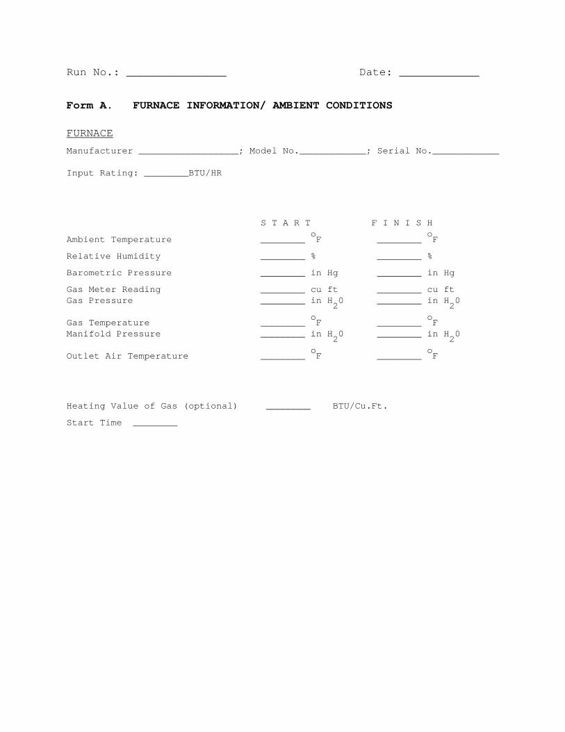
Run No.: _______________ Date: ____________ Form A. FURNACE INFORMATION/ AMBIENT CONDITIONS
FURNACE
Manufacturer __________________; Model No._________ ___; Serial No.____________
Input Rating: ________BTU/HR
S T A R T F I N I S H
Ambient Temperature ________ o
F ________ o
F
Relative Humidity ________ % ________ %
Barometric Pressure ________ in Hg ________ in Hg
Gas Meter Reading ________ cu ft ________ cu ft Gas Pressure ________ in H
20 ________ in H
20
Gas Temperature ________ o
F ________ o
F Manifold Pressure ________ in H
20 ________ in H
20
Outlet Air Temperature ________ o
F ________ o
F
Heating Value of Gas (optional) ________ BTU/Cu.Ft.
Start Time ________

Run No.: _______________ Date: ____________ Form B. EMISSION MEASUREMENTS - Appliances with vents less than 12
inches in diameter.
FURNACE
Type ___________________; Manufacturer __________ ___________;
Model No.________________; Serial No. ____________ ___________.
Z E R O G A S S P A N G A S
ANALYZERS Manufacturer Model Serial No. Val ue Reading Value Reading
CO2
___________ _____ _________ _____ _______ _____ _______
NOx ___________ _____ _________ ___ __ _______ _____ _______
CO ___________ _____ _________ ___ __ _______ _____ _______
CONCENTRATION MEASUREMENTS CO2 - %; NOx - ppm; CO - ppm
CO2 NO X CO
First Minute _____ _____ ____ Second minute _____ _____ ____ Third minute _____ _____ ____ Fourth minute _____ _____ ____ Fifth minute _____ _____ ____

Run No.: _______________ Date: ____________
Form C. EMISSION MEASUREMENTS - Appliances with vents 12 inches in
diameter and larger. FURNACE Type_________; Manufacturer____________; Model No._ _______; Serial No.________
Z E R O G A S S P A N G A S
ANALYZERS Manufacturer Model Serial No. Val ue Reading Value Reading
CO2
___________ _____ _________ _____ _______ _____ _______
NOX
___________ _____ _________ _____ _______ _____ _______
CO ___________ _____ _________ ___ __ _______ _____ _______
CONCENTRATION MEASUREMENTS CO2 - %; NOx - ppm; CO - ppm
Traverse Point CO 2 NOx CO
1 ____ (%) ____ ppm ____ ppm
2 ____ (%) ____ ppm ____ ppm
3 ____ (%) ____ ppm ____ ppm
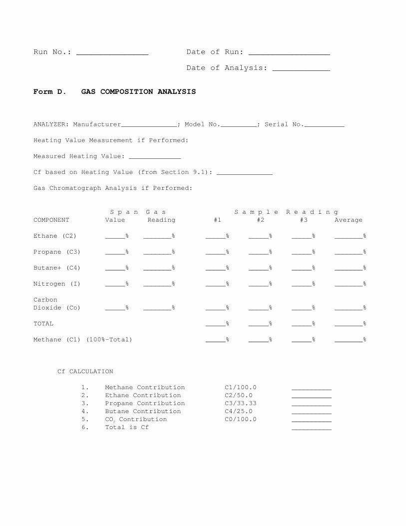
Run No.: _______________ Date of Run: _____________ ____ Date of Analysis: ____________ Form D. GAS COMPOSITION ANALYSIS
ANALYZER: Manufacturer______________; Model No.____ _____; Serial No.__________
Heating Value Measurement if Performed:
Measured Heating Value: _____________
Cf based on Heating Value (from Section 9.1): _____ _________
Gas Chromatograph Analysis if Performed:
S p a n G a s S a m p l e R e a d i n g COMPONENT Value Reading #1 #2 #3 Average Ethane (C2) _____% _______% _____% _____% _____% __ _____% Propane (C3) _____% _______% _____% _____% _____% _ ______% Butane+ (C4) _____% _______% _____% _____% _____% _ ______% Nitrogen (I) _____% _______% _____% _____% _____% _ ______% Carbon Dioxide (Co) _____% _______% _____% _____% _____% _ ______% TOTAL _____% _____% _____% _______% Methane (C1) (100%-Total) _____% _____% _____% ____ ___% Cf CALCULATION 1. Methane Contribution C1/100.0 __________ 2. Ethane Contribution C2/50.0 __________ 3. Propane Contribution C3/33.33 __________ 4. Butane Contribution C4/25.0 __________ 5. CO 2 Contribution C0/100.0 __________ 6. Total is Cf __________
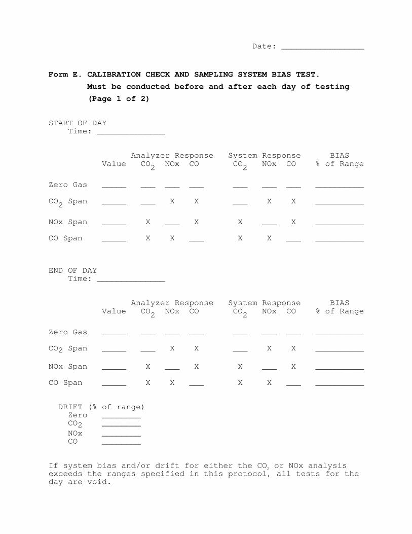
Date: _________________
Form E. CALIBRATION CHECK AND SAMPLING SYSTEM BIAS TEST.
Must be conducted before and after each day of testing
(Page 1 of 2) START OF DAY Time: ______________ Analyzer Response System Respons e BIAS Value CO 2 NOx CO CO 2 NOx CO % of Range
Zero Gas _____ ___ ___ ___ ___ ___ __ _ __________ CO2 Span _____ ___ X X ___ X X __________
NOx Span _____ X ___ X X ___ X __________ CO Span _____ X X ___ X X __ _ __________ END OF DAY Time: ______________ Analyzer Response System Respons e BIAS Value CO 2 NOx CO CO 2 NOx CO % of Range
Zero Gas _____ ___ ___ ___ ___ ___ __ _ __________ CO2 Span _____ ___ X X ___ X X __________ NOx Span _____ X ___ X X ___ X __________ CO Span _____ X X ___ X X __ _ __________ DRIFT (% of range) Zero ________ CO 2 ________ NOx ________ CO ________ If system bias and/or drift for either the CO 2 or NOx analysis exceeds the ranges specified in this protocol, all tests for the day are void.
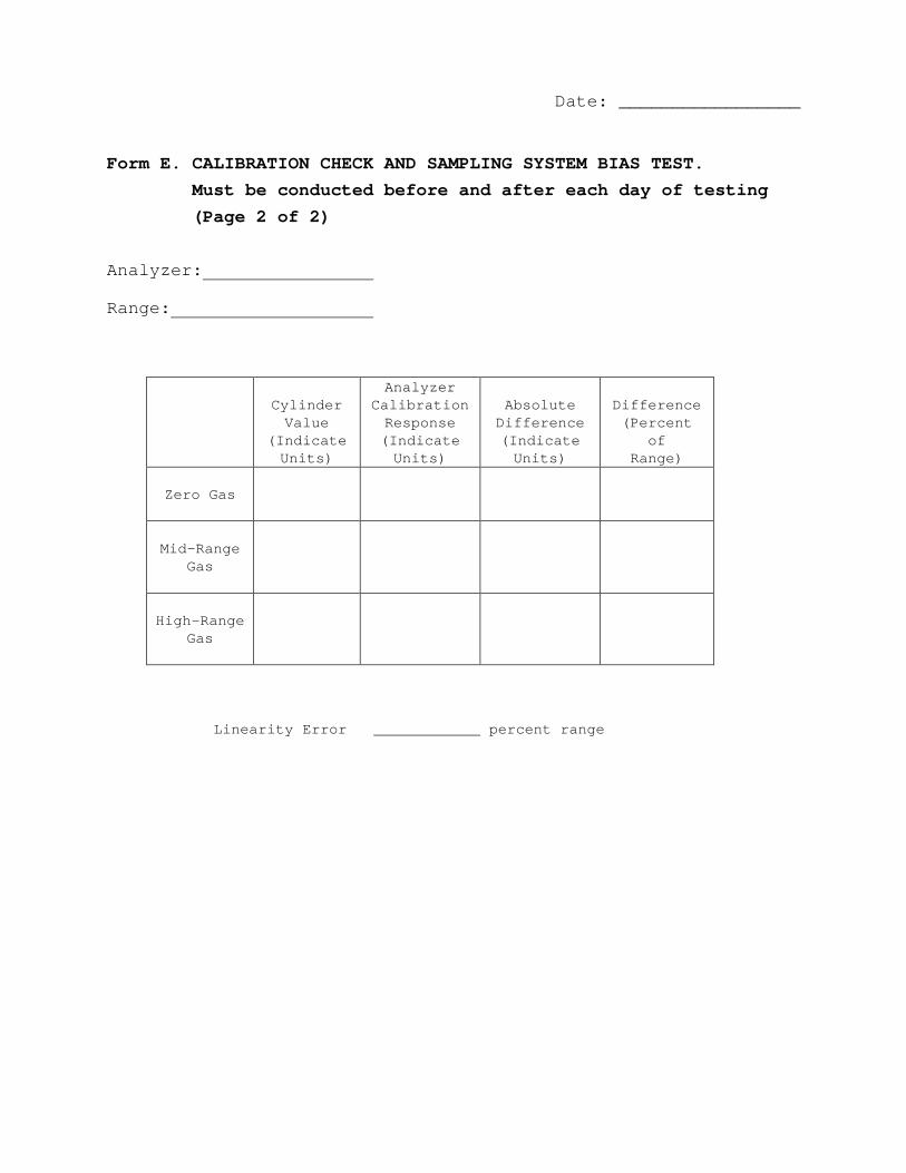
Date: _________________
Form E. CALIBRATION CHECK AND SAMPLING SYSTEM BIAS TEST.
Must be conducted before and after each day of testing
(Page 2 of 2) Analyzer: Range:
Cylinder
Value (Indicate
Units)
Analyzer Calibration
Response (Indicate
Units)
Absolute
Difference (Indicate
Units)
Difference
(Percent of
Range)
Zero Gas
Mid-Range
Gas
High-Range
Gas
Linearity Error percent range
Date: _________________
Form F. NO2 CONVERTER EFFICIENCY TEST. Must be performed
monthly. ANALYZER CALIBRATION Analyzer Value Reading Zero Gas _______ ________ Span Gas _______ ________ CONVERTER TEST Time Analyzer Reading Start _______ ________ Max Reading _______ ________ Finish _______ ________ If final analyzer reading is more than 2.0% less th an the maximum analyzer reading, the converter must be repaired or replaced.
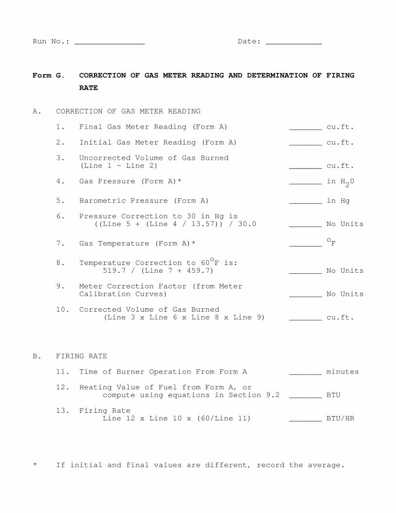
Run No.: _______________ Date: ____________
Form G. CORRECTION OF GAS METER READING AND DETERMINATION OF FIRING
RATE A. CORRECTION OF GAS METER READING 1. Final Gas Meter Reading (Form A) _______ cu.f t. 2. Initial Gas Meter Reading (Form A) _______ cu .ft. 3. Uncorrected Volume of Gas Burned (Line 1 - Line 2) _______ cu.ft. 4. Gas Pressure (Form A)* _______ in H 20
5. Barometric Pressure (Form A) _______ in Hg 6. Pressure Correction to 30 in Hg is ((Line 5 + (Line 4 / 13.57)) / 30.0 _______ N o Units
7. Gas Temperature (Form A)* _______ oF
8. Temperature Correction to 60 oF is: 519.7 / (Line 7 + 459.7) _______ No Units 9. Meter Correction Factor (from Meter Calibration Curves) _______ No Units 10. Corrected Volume of Gas Burned (Line 3 x Line 6 x Line 8 x Line 9) _______ cu.f t. B. FIRING RATE 11. Time of Burner Operation From Form A _______ minutes 12. Heating Value of Fuel from Form A, or compute using equations in Section 9.2 _______ B TU 13. Firing Rate Line 12 x Line 10 x (60/Line 11) _______ BTU/HR * If initial and final values are different, record the average.
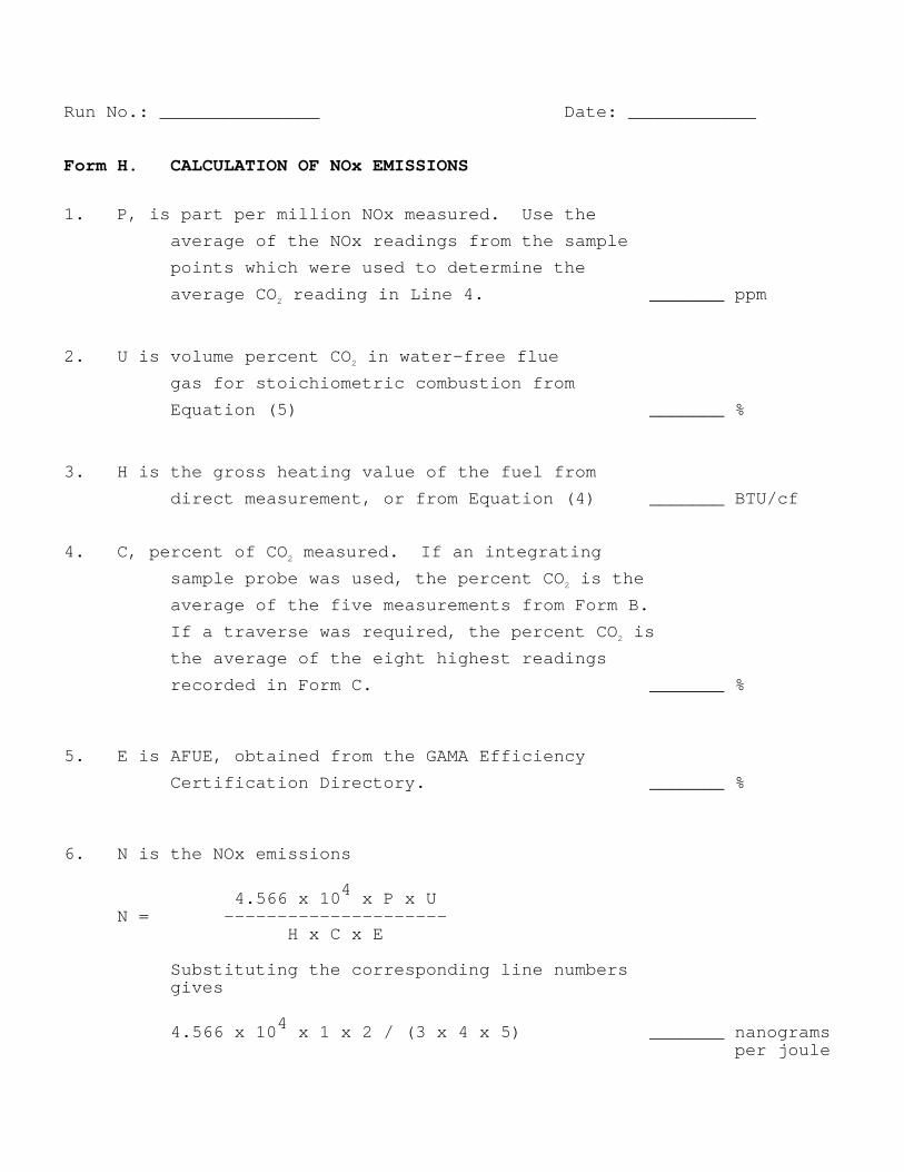
Run No.: _______________ Date: ____________ Form H. CALCULATION OF NOx EMISSIONS
1. P, is part per million NOx measured. Use the
average of the NOx readings from the sample
points which were used to determine the
average CO 2 reading in Line 4. _______ ppm
2. U is volume percent CO 2 in water-free flue
gas for stoichiometric combustion from
Equation (5) _______ %
3. H is the gross heating value of the fuel from
direct measurement, or from Equation (4) _______ BTU/cf 4. C, percent of CO 2 measured. If an integrating
sample probe was used, the percent CO 2 is the
average of the five measurements from Form B.
If a traverse was required, the percent CO 2 is
the average of the eight highest readings
recorded in Form C. _______ %
5. E is AFUE, obtained from the GAMA Efficiency
Certification Directory. _______ % 6. N is the NOx emissions
4.566 x 10 4 x P x U N = ————————————————————— H x C x E Substituting the corresponding line numbers gives
4.566 x 10 4 x 1 x 2 / (3 x 4 x 5) _______ nanograms per joule
APPENDIX A
SCAQMD METHOD 100.1
Method 100.1 can be found at this location: http://www.aqmd.gov/tao/methods/stm/stm-100-1.pdf

APPENDIX B
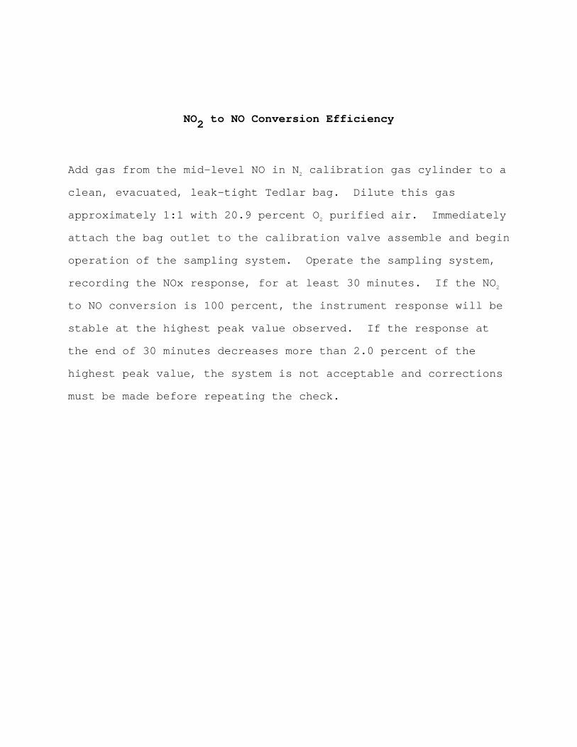
NO2 to NO Conversion Efficiency
NO2 to NO Conversion Efficiency
Add gas from the mid-level NO in N 2 calibration gas cylinder to a
clean, evacuated, leak-tight Tedlar bag. Dilute th is gas
approximately 1:1 with 20.9 percent O 2 purified air. Immediately
attach the bag outlet to the calibration valve asse mble and begin
operation of the sampling system. Operate the samp ling system,
recording the NOx response, for at least 30 minutes . If the NO 2
to NO conversion is 100 percent, the instrument res ponse will be
stable at the highest peak value observed. If the response at
the end of 30 minutes decreases more than 2.0 perce nt of the
highest peak value, the system is not acceptable an d corrections
must be made before repeating the check.