rudders in composite materials - veristar
TRANSCRIPT

Rudders in Composite Materials
September 2013
Guidance Note NI 590 DT R00 E
Marine Division
92571 Neuilly sur Seine Cedex – France Tel: + 33 (0)1 55 24 70 00 – Fax: + 33 (0)1 55 24 7 0 25
Marine website: http://www.veristar.com Email: [email protected]
2013 Bureau Veritas - All rights reserved

ARTICLE 1
1.1. - BUREAU VERITAS is a Society the purpose of whose Marine & Offshore Division (the "Society") isthe classification (" Classification ") of any ship or vessel or offshore unit or structure of any type or part ofit or system therein collectively hereinafter referred to as a "Unit" whether linked to shore, river bed or seabed or not, whether operated or located at sea or in inland waters or partly on land, including submarines,hovercrafts, drilling rigs, offshore installations of any type and of any purpose, their related and ancillaryequipment, subsea or not, such as well head and pipelines, mooring legs and mooring points or otherwiseas decided by the Society.The Society:
• "prepares and publishes Rules for classification, Guidance Notes and other documents (" Rules ");
• "issues Certificates, Attestations and Reports following its interventions (" Certificates ");• "publishes Registers.
1.2. - The Society also participates in the application of National and International Regulations or Stand-ards, in particular by delegation from different Governments. Those activities are hereafter collectively re-ferred to as " Certification ".1.3. - The Society can also provide services related to Classification and Certification such as ship andcompany safety management certification; ship and port security certification, training activities; all activi-ties and duties incidental thereto such as documentation on any supporting means, software, instrumen-tation, measurements, tests and trials on board.
1.4. - The interventions mentioned in 1.1., 1.2. and 1.3. are referred to as " Services ". The party and/or itsrepresentative requesting the services is hereinafter referred to as the " Client ". The Services are pre-pared and carried out on the assumption that the Clients are aware of the International Maritimeand/or Offshore Industry (the "Industry") practices.
1.5. - The Society is neither and may not be considered as an Underwriter, Broker in ship's sale or char-tering, Expert in Unit's valuation, Consulting Engineer, Controller, Naval Architect, Manufacturer, Ship-builder, Repair yard, Charterer or Shipowner who are not relieved of any of their expressed or impliedobligations by the interventions of the Society.ARTICLE 2
2.1. - Classification is the appraisement given by the Society for its Client, at a certain date, following sur-veys by its Surveyors along the lines specified in Articles 3 and 4 hereafter on the level of compliance ofa Unit to its Rules or part of them. This appraisement is represented by a class entered on the Certificatesand periodically transcribed in the Society's Register.
2.2. - Certification is carried out by the Society along the same lines as set out in Articles 3 and 4 hereafterand with reference to the applicable National and International Regulations or Standards.
2.3. - It is incumbent upon the Client to maintain the condition of the Unit after surveys, to presentthe Unit for surveys and to inform the Society without delay of circumstances which may affect thegiven appraisement or cause to modify its scope.2.4. - The Client is to give to the Society all access and information necessary for the safe and efficientperformance of the requested Services. The Client is the sole responsible for the conditions of presenta-tion of the Unit for tests, trials and surveys and the conditions under which tests and trials are carried out.
ARTICLE 33.1. - The Rules, procedures and instructions of the Society take into account at the date of theirpreparation the state of currently available and proven technical knowledge of the Industry. Theyare a collection of minimum requirements but not a standard or a code of construction neither aguide for maintenance, a safety handbook or a guide of professional practices, all of which areassumed to be known in detail and carefully followed at all times by the Client.Committees consisting of personalities from the Industry contribute to the development of those docu-ments.3.2. - The Society only is qualified to apply its Rules and to interpret them. Any reference to themhas no effect unless it involves the Society's intervention.3.3. - The Services of the Society are carried out by professional Surveyors according to the applicableRules and to the Code of Ethics of the Society. Surveyors have authority to decide locally on matters re-lated to classification and certification of the Units, unless the Rules provide otherwise.
3.4. - The operations of the Society in providing its Services are exclusively conducted by way of ran-dom inspections and do not in any circumstances involve monitoring or exhaustive verification.
ARTICLE 44.1. - The Society, acting by reference to its Rules:
• "reviews the construction arrangements of the Units as shown on the documents presented by the Cli-ent;
• "conducts surveys at the place of their construction;
• "classes Units and enters their class in its Register;• "surveys periodically the Units in service to note that the requirements for the maintenance of class are
met. The Client is to inform the Society without delay of circumstances which may cause the date or theextent of the surveys to be changed.ARTICLE 5
5.1. - The Society acts as a provider of services. This cannot be construed as an obligation bearingon the Society to obtain a result or as a warranty.
5.2. - The certificates issued by the Society pursuant to 5.1. here above are a statement on the levelof compliance of the Unit to its Rules or to the documents of reference for the Services provided for.
In particular, the Society does not engage in any work relating to the design, building, productionor repair checks, neither in the operation of the Units or in their trade, neither in any advisory serv-ices, and cannot be held liable on those accounts. Its certificates cannot be construed as an im-plied or express warranty of safety, fitness for the purpose, seaworthiness of the Unit or of its valuefor sale, insurance or chartering.
5.3. - The Society does not declare the acceptance or commissioning of a Unit, nor of its construc-tion in conformity with its design, that being the exclusive responsibility of its owner or builder.
5.4. - The Services of the Society cannot create any obligation bearing on the Society or constitute anywarranty of proper operation, beyond any representation set forth in the Rules, of any Unit, equipment ormachinery, computer software of any sort or other comparable concepts that has been subject to any sur-vey by the Society.
ARTICLE 6
6.1. - The Society accepts no responsibility for the use of information related to its Services which was notprovided for the purpose by the Society or with its assistance.
6.2. - If the Services of the Society or their omission cause to the Client a damage which is provedto be the direct and reasonably foreseeable consequence of an error or omission of the Society,its liability towards the Client is limited to ten times the amount of fee paid for the Service havingcaused the damage, provided however that this limit shall be subject to a minimum of eight thou-sand (8,000) Euro, and to a maximum which is the greater of eight hundred thousand (800,000)Euro and one and a half times the above mentioned fee. These limits apply regardless of fault in-cluding breach of contract, breach of warranty, tort, strict liability, breach of statute, etc.The Society bears no liability for indirect or consequential loss whether arising naturally or not asa consequence of the Services or their omission such as loss of revenue, loss of profit, loss of pro-duction, loss relative to other contracts and indemnities for termination of other agreements.
6.3. - All claims are to be presented to the Society in writing within three months of the date when the Serv-ices were supplied or (if later) the date when the events which are relied on of were first known to the Client,and any claim which is not so presented shall be deemed waived and absolutely barred. Time is to be in-terrupted thereafter with the same periodicity. ARTICLE 7
7.1. - Requests for Services are to be in writing.
7.2. - Either the Client or the Society can terminate as of right the requested Services after givingthe other party thirty days' written notice, for convenience, and without prejudice to the provisionsin Article 8 hereunder.
7.3. - The class granted to the concerned Units and the previously issued certificates remain valid until thedate of effect of the notice issued according to 7.2. here above subject to compliance with 2.3. here aboveand Article 8 hereunder.7.4. - The contract for classification and/or certification of a Unit cannot be transferred neither assigned.
ARTICLE 8
8.1. - The Services of the Society, whether completed or not, involve, for the part carried out, the paymentof fee upon receipt of the invoice and the reimbursement of the expenses incurred.
8.2. - Overdue amounts are increased as of right by interest in accordance with the applicable leg-islation.
8.3. - The class of a Unit may be suspended in the event of non-payment of fee after a first unfruitfulnotification to pay.
ARTICLE 9
9.1. - The documents and data provided to or prepared by the Society for its Services, and the informationavailable to the Society, are treated as confidential. However:
• "Clients have access to the data they have provided to the Society and, during the period of classifica-tion of the Unit for them, to the classification file consisting of survey reports and certificates which have been prepared at any time by the Society for the classification of the Unit ;
• "copy of the documents made available for the classification of the Unit and of available survey reports can be handed over to another Classification Society, where appropriate, in case of the Unit's transfer of class;
• "the data relative to the evolution of the Register, to the class suspension and to the survey status of the Units, as well as general technical information related to hull and equipment damages, may be passed on to IACS (International Association of Classification Societies) according to the association working rules;
• "the certificates, documents and information relative to the Units classed with the Society may be reviewed during certificating bodies audits and are disclosed upon order of the concerned governmen-tal or inter-governmental authorities or of a Court having jurisdiction.
The documents and data are subject to a file management plan.
ARTICLE 10
10.1. - Any delay or shortcoming in the performance of its Services by the Society arising from an eventnot reasonably foreseeable by or beyond the control of the Society shall be deemed not to be a breach ofcontract.
ARTICLE 11
11.1. - In case of diverging opinions during surveys between the Client and the Society's surveyor, the So-ciety may designate another of its surveyors at the request of the Client.
11.2. - Disagreements of a technical nature between the Client and the Society can be submitted by theSociety to the advice of its Marine Advisory Committee.
ARTICLE 1212.1. - Disputes over the Services carried out by delegation of Governments are assessed within theframework of the applicable agreements with the States, international Conventions and national rules.12.2. - Disputes arising out of the payment of the Society's invoices by the Client are submitted to the Courtof Nanterre, France, or to another Court as deemed fit by the Society.12.3. - Other disputes over the present General Conditions or over the Services of the Society areexclusively submitted to arbitration, by three arbitrators, in London according to the ArbitrationAct 1996 or any statutory modification or re-enactment thereof. The contract between the Societyand the Client shall be governed by English law.
ARTICLE 13
13.1. - These General Conditions constitute the sole contractual obligations binding together theSociety and the Client, to the exclusion of all other representation, statements, terms, conditionswhether express or implied. They may be varied in writing by mutual agreement. They are not var-ied by any purchase order or other document of the Client serving similar purpose.13.2. - The invalidity of one or more stipulations of the present General Conditions does not affect the va-lidity of the remaining provisions. 13.3. - The definitions herein take precedence over any definitions serving the same purpose which mayappear in other documents issued by the Society.
BV Mod. Ad. ME 545 L - 7 January 2013
MARINE & OFFSHORE DIVISIONGENERAL CONDITIONS

GUIDANCE NOTE NI 590
Rudders in Composite Materials
SECTION 1 GENERAL APPROACH
SECTION 2 DIRECT CALCULATIONS BASED ON FE TECHNIQUES
September 2013

Section 1 General Approach
1 General 5
1.1 Application1.2 Surveys for the maintenance of class1.3 Documentation to be submitted
2 Materials and manufacturing process 5
2.1 General2.2 Materials2.3 Construction survey
3 Design loads and stress analysis 6
3.1 Design loads3.2 Stress analysis
4 Section characteristics of rudder elements 7
4.1 General4.2 Calculation of element rigidity
5 Rudder stock scantling 8
5.1 Scantling criterion5.2 Additional criterion
6 Rudder stock couplings 9
6.1 Connection to the steering gear6.2 Connection to the rudder blade
7 Rudder stock arrangement 12
7.1 Rudder stock liners and inserts
8 Rudder blade and flap 12
8.1 Rudder blade and flap structure8.2 Scantling criteria
9 Rudder trunk 13
9.1 General
10 Rudder horn 13
10.1 General
11 Scantlings and safety coefficients 13
11.1 Scantling basis11.2 Partial safety coefficients
2 Bureau Veritas September 2013

Section 2 Direct Calculations based on FE Techniques
1 General 15
1.1 Introduction
2 FE models and main aspects to consider 15
2.1 Types of FE models covered by this guidance2.2 Mesh generation and choice of elements2.3 Material mechanical properties2.4 Material local directions2.5 Boundary conditions2.6 Loading cases2.7 Stress failure criteria2.8 Other aspects
3 Global calculations with composite beam sections 17
3.1 General3.2 Methodology3.3 Composite beam cross-sections analyses3.4 Beam section analysis with composite cross-sections
4 Global calculations with composite shell sections 18
4.1 General4.2 Mesh generation for conventional shell elements4.3 Material properties for conventional shell elements4.4 Layerwised data, material directions and stacking sequence4.5 Contact in way of pintle bearings and stock bearings
5 Cone coupling with composite axisymmetric elements 21
5.1 General5.2 The FE axisymmetric model
6 FE models with 3D solid elements 23
6.1 General6.2 From 2D axisymmetric to 3D solid elements6.3 Material properties for 3D solid continuum elements6.4 Transformation equations for stress/strain and compliance/stiffness tensors6.5 Layerwised data for 3D brick elements and stacking direction6.6 Material local directions for 3D solids generated by revolution of a 2D model6.7 Equivalent material properties for a laminate made of fully orthotropic layers
September 2013 Bureau Veritas 3

4 Bureau Veritas September 2013
NI 590, Sec 1
SECTION 1 GENERAL APPROACH
1 General
1.1 Application
1.1.1 The requirements of this Guidance Note apply to rud-der stock, rudder blade and flap, rudder trunk and rudder horn built in composite materials.
1.1.2 The purpose of this Guidance Note is to define and specify:
• a methodology to assess scantling of rudders
• the requirements for the manufacture inspections and tests
for rudders, made totally or partialy in composite materials.
This Guidance Note is to be applied in addition to the Rule Notes:
• NR467 Rules for the Classification of Steel Ships, Pt B, Ch 10, Sec 1, and
• NR546 Hull in Composite Materials and Plywood.
Note 1: As a general rule, this Guidance Note is not applicable to rudder built in composite materials for ship classed with the service notation yacht and charter yacht, where the NR500 Rules for the Classification and the Certification of Yachts, is applicable.
1.1.3 General arrangement of rudder (effective means to support the weight of rudder, to prevent the rudder from lift, to prevent water from entering the steering gear compart-ment,...) are to be as defined in NR467, Pt B, Ch10, Sec 1.
The elements made of steel in the rudder arrangement are not covered by this Guidance Note and are to be in accor-dance with NR467, Pt B, Ch 10, Sec 1.
1.1.4 The steering gear systems are not covered by this Guidance Note and are to be as defined in NR467, Pt C, Ch 1, Sec 11.
1.1.5 As a general rule, elements of the rudder system which are in direct contact with the ice, for ships having an additional notation for navigation in ice, are not to be in composite materials.
1.2 Surveys for the maintenance of class
1.2.1 In addition to the extend and scope of the periodical in-service surveys to be carried out according to NR467, Part A, an inspection plan for in-service surveys of compos-ite rudder parts is to be provided by the manufacturer, including the:
• frequency of survey
• list of items to be inspected including acceptance crite-ria of elements checked,
• repair procedure, in case of wear/damage of rudder components,
• monitoring system, if provided, to assess the rudder stock deformation, the conical coupling pressure,...
Attention is drawn to special requirements from the ship Flag Administration which may be taken into account and not included in this Guidance Note.
1.3 Documentation to be submitted
1.3.1 The plan showing the structural arrangement of the rudder, the scantling of the rudder stock and rudder blade, the connections, the reinforcements in way of bearings,... are to be submitted to the Society for approval.
In addition to the structural drawings, the following infor-mation are to be submitted:
• Raw materials: technical specifications of suppliers with indication of the types, trademark and references of the raw materials, specifying:
- for resins and adhesives: system (polyester, vinyles-ter or epoxy), density, Young modulus, shear modu-lus, Poisson coefficient, breaking strength and elongation at break
- for reinforcements (unidirectional reinforcements, woven roving, mats): fibre’s quality (type, density and breaking strength, Young modulus and Poisson coefficient in fibre direction and normal to fibre direction), mass per square meter, thickness and, for woven roving, weft-wrap distribution
- for core materials: type and quality, density, tensile, compression and shear breaking stresses and elastic-ity moduli.
• Laminate: arrangement of the laminates for the various elements (thickness, definition of the successive layers of reinforcement, mass of reinforcement per square meter in layers, proportion in mass or in volume of rein-forcement of each layer, directions of roving layers and unidirectional reinforcements, dimension of lap joints between layers).
• Manufacturing process: see [2.3].
2 Materials and manufacturing process
2.1 General
2.1.1 The mechanical characteristics of a composite struc-ture are directly depending on the type of raw materials used and the manufacturing process adopted for the building.
The present article defines the requirements regarding the homologation of raw materials and the construction process survey of rudder built in composite material.
September 2013 Bureau Veritas 5
NI 590, Sec 1
2.2 Materials
2.2.1 General
The raw materials considered are:
• thermoset resin’s systems
• glass, carbon or para-aramid based reinforcement fabrics.
• core materials
Other raw materials may be considered, provided their specifications are submitted to the Society for acceptance.
General informations on the “state of the art“ about main raw materials and minimum rule mechanical characteristics are given in the NR546.
2.2.2 Certification of raw material
As a general rule, the main raw materials (resins, reinforce-ment fabrics and cores) used for rudder elements put on board are to be certified by the Society.
The process of raw material approval is described in the NR546, Sec 10, [2].
2.3 Construction survey
2.3.1 General
During the manufacturing process of the rudder elements, survey at yard and mechanical test are to be carried out by the Society.
The manufacturing process considered are lay-ups (spray and hand), vacuums (infusion), prepreg and winding.
Other manufacturing process may be accepted on a case by case basis.
2.3.2 Mechanical test
Mechanical and physico-chemical tests are to be performed on test samples produced by the shipyard and representative of the construction of the rudder elements (same raw materi-als, same laminate lay-up and same construction process).
These tests are to be defined on a case by case basis by the Society, and the results are to be compared with the theoret-ical properties of the laminates characteristics defined in this Guidance Note.
The general requirements about mechanical tests are defined in the NR546, Section 10.
Where deemed necessary by the Society, prototype model of a set of elements of the rudder may be requested to be tested.
2.3.3 Construction survey
Inspections at yard during the rudder elements construction are defined in the NR546, Section 10.
3 Design loads and stress analysis
3.1 Design loads
3.1.1 The rudder force CR, in N, applied to the rudder is to be obtained as defined in the NR467, Pt B, Ch 10, Sec 1, taking into account the maximum ahead and astern speed of the ship, the location of the rudder in relation to the pro-peller jet and the shape of the rudder blade.
The forces acting on the rudder blade may induce in the rudder structure the following loads:
• bending moment, torque and shear force in the rudder stock
• bending moment, torque and shear force in the rudder blade and in the flat
• bending moment, torque and shear force in the rudder trunk
• support forces at pintle and rudder stock bearings
• bending moment, torque and shear force in the rudder horn.
These moments, shear force and support forces are defined in the NR467, Pt B, Ch 10, App 1 in relation to the type of rudder.
Bending moment, torque and shear force applied to the rudder structure may be defined by direct calculation to be submitted to the Society.Note 1: Where rudder is supported by a rudder horn, a direct cal-culation taking into account the elastic support of the rudder horn may be considered to determine the bending moment and shear force applied to the rudder stock.
3.2 Stress analysis
3.2.1 Stress calculationFor each element of the rudder built in composite material (rudder stock, blade and flap, trunk or horn), the stress anal-ysis is carried out taking into account:
• the moments and forces defined in [3.1.1]
• the geometry of the considered element
• the global rigidity of laminates of the considered element.
Strains and curved deformation of laminates of the consid-ered element are to be calculated at the laminate median plan and allow to estimate the stresses in the layers of the laminate.
The mechanical characteristics of the individual layers and of the laminates are to be calculated as defined in the NR546, or by an equivalent method.
Steps of the calculation and associated Rules Note of the Society necessary to carry out these calculations are given in Tab 1.
3.2.2 Safety coefficientsFor each layer of the different laminates of the element con-sidered, the safety coefficients, equal to the ratio between the applied stress and the theoretical breaking stresses of the layer as defined in the NR546, are to be calculated. These safety coefficients are to be at least equal to the mini-mum rules safety coefficients as defined in [11].
6 Bureau Veritas September 2013

NI 590, Sec 1
Table 1 : Steps for stresses calculation
4 Section characteristics of rudder elements
4.1 General
4.1.1 As a general rule, the bending rigidity ExIx , the tor-sional rigidity GxyIT and the effective shear rigidity GxyS of the element of the rudder are to be determined by direct calculation.
For circular or rectangular hollow profiles, formulae defined in [4.2] may be used, instead of determination by direct cal-culation.
4.2 Calculation of element rigidity
4.2.1 Elastic coefficient of laminate
The following moduli, in N/mm2, which characterize the laminate, are to be calculated as defined in the NR546, Sec 6, [2]:
• EX tensile modulus in the direction X of the laminate
• EY tensile modulus in the direction Y of the laminate
• GXY shear plane modulus in the plane of the laminate.
4.2.2 Circular hollow profile rigidityThe bending and torsional rigidity, the effective shear rigid-ity and the tensile rigidity of a circular hollow profile are to be calculated as follows:
• bending rigidities, in Nmm2, according to the two main axes:
• torsional rigidity, in Nmm2:
• effective shear rigidity, in N:
• tensile rigidity, in N:
where:D, d : Respectively the outer and inner diameter, in
mm, of the circular hollow profile.
4.2.3 Rectangular hollow profile rigidityThe bending rigidity, the torsional rigidity, the effective shear rigidity and the tensile rigidity of a rectangular hollow profile are to be calculated as follows:
• bending rigidity EX1IX, in Nmm2, and effective shear rigidity GXY1SX, in N, according to X axis:
where:EX1, GXY1 : Young modulus and shear modulus, in
N/mm2 calculated in the element 1 as shown on Fig 1, in accordance with NR546, Sec 6, [2]
EX2 : Young modulus, in N/mm2 calculated in the element 2 as shown on Fig 1, in accordance with NR546, Sec 6, [2]
StepsCalculation Reference
1 Force and torque acting on the rudder
Rudder force CR and force per unit length acting on the rudder body in relation with the type of rudder
NR467, Ch 10, Sec 1 and Ch10, App 1
Rudder torque applied to the rudder stock NR467, Ch 10, Sec 1
Bending moments, shear forces, support forces and torsion moments applied to the different elements of the rudder
NR467, Ch 10, App 1
2 Laminate characteristics of the elements of the rudder
Geometric characteristics, rigidity and theoretical breaking stresses of individual layers
NR546, Sec 5
Description of the laminate (position of the individual layers, orienta-tion of the reinforcements)
NR546, Sec 6
Global elastic coefficients and mechanical characteristics of the lami-nate in the axis the element of the rudder
NR546, Sec 6
3 Element of the rudder Calculation of the sections and the rigidities of the element of the rud-der under consideration (rudder stock, blade or flap, trunk, horn)
[4]
Strains deformation of the median plan of each laminates of the con-sidered elements under loads calculated in step 1
[5] to [10]
4 Laminate stress analysis Calculation of the stresses for each individual layer in its own local axis
NR546, Sec 6
Calculation of the safety coefficients for each individual layer [11]
ExIxExπ D4 d4–( )
64--------------------------------=
GXYITGXYπ D4 d4–( )
32------------------------------------=
GXYSGXYπ D2 d2–( )
8------------------------------------=
EXAXπ4--- D2 d2–( )EX=
EX1IX 2BXe3
X
12-------------- BXexv
2Y+
EX1eYB3
Y
12--------------EX2+=
GXY1SX 2GXY1BXeX=
September 2013 Bureau Veritas 7

NI 590, Sec 1
Figure 1 : Rectangular hollow profile dimensions
• bending rigidity EX2IY, in Nmm2, and effective shear rigidity GXY2SY, in N, according to Y axis:
where:
EX1, GXY : Young modulus and shear modulus calcu-lated in the element 1 as shown on Fig 1, in accordance with NR546, Sec 6, [2]
EX2 : Young modulus calculated in the element 2 as shown on Fig 1, in accordance with NR546, Sec 6, [2]
• torsional rigidity, in Nmm2:
where:
GXY1, GXY2: Shear moduli, in N/mm2, respectively calcu-lated in accordance with NR546, Sec 6, [2], in the element 1 and the element 2 (see Fig 1).
• tensile rigidity, in N:
where:
5 Rudder stock scantling
5.1 Scantling criterion
5.1.1 GeneralThe scantling of the rudder stock is based for a state of stress in each layer of the laminate making up the rudder stock, induced by torque moment MTR, bending moment MB and shear force F.
The values of the moments, in KNm, and the shear forces, in N, and the combination of these moments and shear force according to the section of the rudder stock under consider-ation are defined in the NR467, Part B, Ch 10, App 1.
As a general rule, the requirements to rudder stock scantling are applicable regardless of liners generally provided in way of bearings, cone couplings,...
The stresses in the individual layers of the laminates making up the rudder stock are to be calculated as defined in the NR546, Section 6, taking into account the strains defined in[5.1.2].
The scantling criteria are based on safety coefficients as defined in [11].
5.1.2 Rudder stock strainsThe rudder stock laminate strains, calculated at the median plan of the laminates, at the section considered of the rud-der stock may be estimated as follows:
a) Shear strain, in %, in the plan of the rudder section induced by the torque moment:
where:
MTR : Torque moment, in KNm
Vmp : Distance, in mm, between the torsion centre of the rudder stock profile and the median plan of the laminate
GXTIT : Torsional rigidity, in Nmm2, as defined in[4].
b) Bending strain, in %, in the median plan of the lami-nates making up the rudder stock induced by the bend-ing moment:
where:
MB : Bending moment, in KNm
Vmp : Distance, in mm, between the bending cen-tre of the rudder stock profile and the median plan of the laminate
EXiIi : Bending rigidity, in Nmm2, as defined in [4].Note 1: The strain analysis of each layer of the laminate of the rud-
der stock may be carried out by the analysis of an equivalent sandwich having the same lay-up than the rudder stock with a core thickness equal to dS and with a width of one meter, loaded by a bending moment M’B, in KN.m, equal to:
where:
II : Inertia of the rudder stock
IS : Inertia of the equivalent sandwich of one meter width.
c) Shear strain perpendicular to the rudder section induced by the shear force:
where:
F : Shear force, in KN
GXYiSi : Effective shear rigidity, in N, as defined in[4].
��
������
��
��
�
�
����� �
����� �
����� �
����� �
��
��
�������� �� ����� ��� �� ����� � � ����� �
EX2IY 2BYe3
Y
12-------------- BYeYv2
X+ EX2
eXB3X
12--------------EX1+=
GXY2SY 2GXY2BYeY=
GXYIT2 bxby( )2
bX
eX
-----GXY1bY
eY
-----GXY2+------------------------------------------G2
moy=
GmoyGXY1bXeX GXY2bYeY+
bXeX bYeY+-----------------------------------------------------=
EXAX 2 BXeX ByeY+( )Emoy=
EmoyBXeXEX1 BYeYEX2+
BXeX BYeY+----------------------------------------------=
γXYMTRVmp
GXTIT
-------------------108=
εXiMBVmp
EXiII
-----------------108=
M′B
II
IS
---MB=
γXZF
GXYiSi
---------------103=
8 Bureau Veritas September 2013
NI 590, Sec 1
5.2 Additional criterion
5.2.1 Rudder stock analysis by finite element calculation
If deemed necessary, the Society may require in addition to the rudder stock laminate strains calculated as defined in[5.1] at the median plan of the laminates, a finite element analysis or an equivalent calculation of the rudder stock, based on the hypothesis defined in Sec 2.
5.2.2 Rudder stock deformation
Large rudder stock deformations are to be avoided in order to avoid edge pressure in way of bearings (see [7.1]) or fail-ure of the rudder arrangements.
The Society may require an additional check of the rudder stock scantling by finite element calculation, based on the hypothesis defined in Sec 2, to make sure that the deforma-tion are acceptable.
6 Rudder stock couplings
6.1 Connection to the steering gear
6.1.1 General
The requirements of this sub-article apply in addition to those specified in the NR467, Pt C, Ch 11, Sec 11.
The rudder stock connection to the steering gear is to be examined taking into account the full torque moment induced by the rudder blade.
In addition, it may be necessary to take into account the fol-lowing loadings:
• weight of the rudder body when the effective means for supporting the rudder are transmitted to the coupling
• bending moments when the steering gear is located in a rudder stock area transmitting bending moment to the coupling.
6.1.2 Connection by bolted joint
Bolting connection are to be examined by direct calculation taking into account the:
• loadings defined in [6.1.1]
• effective shear sections of the bolts and/or shear bushes
• prestress in the bolts.
The admissible shear stress τa, in N/mm2, induced by the torque only and the admissible Von Mises combined stress σa, in N/mm2, in the bolts and/or shear bushes are to be in compliance with the following formulae:
τa < 0,20 Re’
σa < 0,55 Re’
where:
R’e : Design yield strength in N/mm2, determined by the following formula:
• R’e = Re where R ≥ 1,4 Re
• R’e = 0,417 (Re + R) where R < 1,4 Re
Re : Value of the minimum specified yield strength of the bolts and/or shear bushes, in N/mm2
R : Value of the minimum specified tensile strength of the bolts and/or shear bushes, in N/mm2.
6.1.3 Connection by gluing jointWhere the connection is totally or partially carried out by gluing joint, the connection is to be examined by direct cal-culation taking into account the:
• loadings defined in [6.1.1]
• mechanical characteristics of the joint (in relation to the adhesive type and gluing process) as defined in the NR546.
As a general rule, the minimum admissible safety factor SF (equal to the ratio between the minimum breaking stress of the adhesive and the actual stress), applicable to the shear stress in the gluing joint is to be greater than:
SF = 6,5 CF CV
where:
CF : Coefficient taking into account the gluing pro-cess, and generally taken equal to:
• CF = 1,4 in case of a vacuum process with rising temperature
• CF = 1,5 in case of vacuum process
• CF = 1,7 in the other cases
CV : Coefficient taking into account the ageing effect on the adhesive joint, to be taken as a general rule not less than 1,2.
Combination of mechanical and glued connections will be considered on a case by case basis.
Where deemed necessary by the Society, mechanical test on representative gluing joint samples may be required.
6.1.4 Connection by cone coupling arrangementThis requirement applies for coupling arrangement made by friction coupling induced by a conical arrangement between the circular rudder stock and the tiller boss of the steering gear.
The theoretical parameters to estimate the characteristics of the cone coupling arrangement are as follows:
a) pressure ptg in N/mm2, to apply between the rudder stock and the tiller boss to ensure the transmission of the torque:
where:
MTR : Rudder torque, in KN.m, defined in [3.1.1]
η : Coefficient to be taken equal to:
• η = 1 for keyed connections
• η = 2 for keyless connections
dm : Mean diameter, in mm, of the conical bore as shown on Fig 2
μ : Friction coefficient after mounting (taken equal to 0,15 for steel/steel friction)
Ptg2MTRη
πdm2ts μ2 c2
4-----–
-------------------------------------106=
September 2013 Bureau Veritas 9
NI 590, Sec 1
c : Taper of conical coupling measured on diameter, to be obtained from following for-mula:
ts, dU, d0 : Geometrical parameters of the coupling, as shown on Fig 2
b) value tg, in mm, of the minimum tightening between the rudder stock and the tiller boss:
where:
Db, ds and dm: Dimensions, in m, of the rudder stock and tiller boss, as shown on Fig 2
Eb : Young modulus, in N/mm2 of the tiller boss
ESy, ESz : Young moduli, in N/mm2 of the rudder stock, in the circumferential and radial directions, respectively
νb : Poisson’s ratio of the tiller boss
νSzy : Poisson’s ratio of the rudder stock in the cir-cumferential direction (y-direction) due to a stress in the radial direction (z-direction)
c) push-up length value Δ0, in mm, of the rudder stock tapered part into the tiller boss:
Non circular rudder stock are to be examined on a case by case basis.
As a general rule, a finite element calculation based on the hypothesis defined in Sec 2 is to be carried out in order to take into account the following additional stresses:
• For the rudder stock: longitudinal tensile and radial compressive stresses
• For the tiller hub: radial tensile stresses.
The minimum rule safety coefficient SFCS for an analysis of the combined stress is to be as defined in [11.1.3], with a value of the partial safety factor CCS taken not less than the value given in Tab 2.
6.1.5 Insert connection and local rudder stock scantling
The connection between the insert and the rudder stock is to be examined on a case by case basis. The tensile force, in N, induced by the push-up length and transmitted to the rudder stock by the insert may be estimated by the follow-ing formula:
where:
ESx : Young modulus, in N/mm2, of the rudder stock as defined in the NR546, in the axial direction
ESy, ESz : Young moduli, in N/mm2 of the rudder stock, in the circumferential and radial directions, respectively
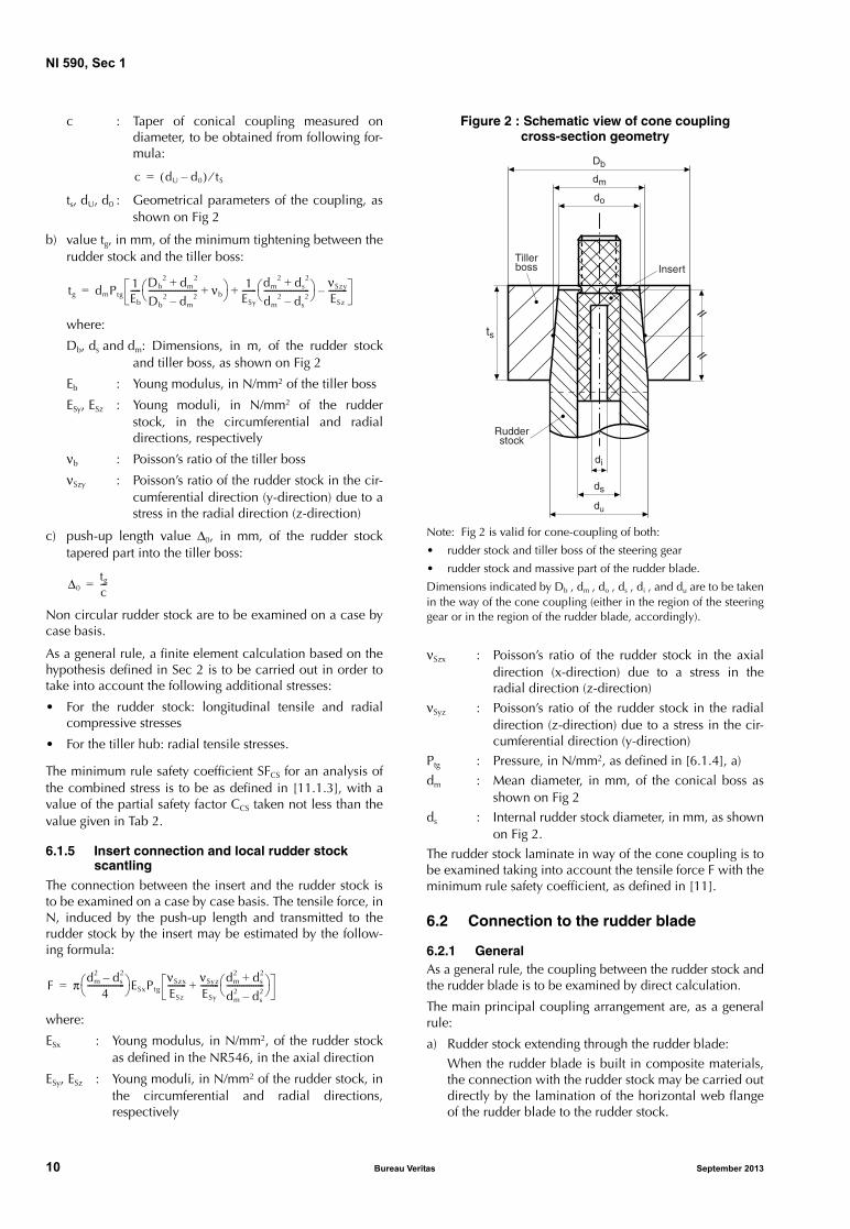
Figure 2 : Schematic view of cone coupling cross-section geometry
Note: Fig 2 is valid for cone-coupling of both:
• rudder stock and tiller boss of the steering gear
• rudder stock and massive part of the rudder blade.
Dimensions indicated by Db , dm , do , ds , di , and du are to be taken in the way of the cone coupling (either in the region of the steering gear or in the region of the rudder blade, accordingly).
νSzx : Poisson’s ratio of the rudder stock in the axial direction (x-direction) due to a stress in the radial direction (z-direction)
νSyz : Poisson’s ratio of the rudder stock in the radial direction (z-direction) due to a stress in the cir-cumferential direction (y-direction)
Ptg : Pressure, in N/mm2, as defined in [6.1.4], a)
dm : Mean diameter, in mm, of the conical boss as shown on Fig 2
ds : Internal rudder stock diameter, in mm, as shown on Fig 2.
The rudder stock laminate in way of the cone coupling is to be examined taking into account the tensile force F with the minimum rule safety coefficient, as defined in [11].
6.2 Connection to the rudder blade
6.2.1 GeneralAs a general rule, the coupling between the rudder stock and the rudder blade is to be examined by direct calculation.
The main principal coupling arrangement are, as a general rule:
a) Rudder stock extending through the rudder blade:
When the rudder blade is built in composite materials, the connection with the rudder stock may be carried out directly by the lamination of the horizontal web flange of the rudder blade to the rudder stock.
c dU d0–( ) tS⁄=
tg dmPtg1Eb
----- Db2 dm
2+Db
2 dm2–
------------------------ νb+ 1
ESy
------- dm2 ds
2+dm
2 ds2–
---------------------- νSzy
ESz
---------–+=
Δ0tg
c---=
F π dm2 ds
2–4
------------------ ESxPtg
νSzx
ESz
--------- νSyz
ESy
--------- dm2 ds
2+dm
2 ds2–
------------------ +=
Rudderstock
Tillerboss Insert
//
//
ds
do
dm
du
Db
ts
di
10 Bureau Veritas September 2013

NI 590, Sec 1
As a rule, this connection is to be able to transmit only the torque moment induced by the rudder blade and is to be as defined in [8].
The minimum rule safety coefficient are to be as defined in [11].
b) Rudder stock connected by cone coupling:
The connection by cone coupling is to be able to trans-mit the torque moment and is to be as defined in[6.1.4].
When the cone coupling is to transmit a bending moment in addition to the torque moment, the push-up length Δt, in mm, to provide in the conical arrangement to transmit by friction the torque and the bending moments is to be not less than:
where:
tt : value, in mm, of the minimum tightening in the cone coupling, taken equal to:
c : Taper of conical coupling measured on diam-eter, to be obtained from following formula:
with:
pt : Push-up pressure, in N/mm2, to be taken not less than the greater value of:
where:
Mb : Bending moment, in N.m, defined in [3.1.1]
MTR : Rudder torque, in N.m, defined in [3.1.1]
dm : Mean diameter, in mm, of the conical boss, as shown schematically on Fig 2
Db, ds, dU, d0, tS:Geometrical dimensions of the cone coupling arrangement, in mm, as shown schematically on Fig 2, to be taken in way of the massive part of the rudder blade
Eb : Young modulus, in N/mm2 of the boss cone coupling (massive part)
ESy, ESz : Young moduli, in N/mm2 of the rudder stock, in the circumferential and radial directions, respectively
νb : Poisson’s ratio of the boss cone coupling (massive part)
νSzy : Poisson’s ratio of the rudder stock in the cir-cumferential direction (y-direction) due to a stress in the radial direction (z-direction)
η : Coefficient to be taken equal to:
• η = 1 for keyed connections
• η = 2 for keyless connections
μ : Friction coefficient after mounting (taken equal to 0,15 for steel/steel friction).
Non circular rudder stock are to be examined on a case by case basis.
As a general rule, a finite element calculation based on the hypothesis defined in Sec 2 is to be carried out in order to take into account the following additional stresses:
• For the rudder stock: longitudinal tensile and radial compressive stresses
• For the boss cone coupling: radial tensile stresses.
The minimum rule safety coefficient SFCS for an analysis of the combined stress is to be as defined in [11.1.3], with a value of the partial safety factor CCS taken not less than the value given in Tab 2.
6.2.2 Insert connection and local rudder stock scantling
The connection between the insert and the rudder stock is to be examined on a case by case basis. The tensile force, in N, induced by the push-up length and transmitted to the rudder stock by the insert may be estimated by the follow-ing formula:
where:
ESx : Young modulus, in N/mm2, of the rudder stock as defined in the NR546, in the axial direction
ESy, ESz : Young moduli, in N/mm2 of the rudder stock, in the circumferential and radial directions, respectively
νSzx : Poisson’s ratio of the rudder stock in the axial direction (x-direction) due to a stress in the radial direction (z-direction)
νSyz : Poisson’s ratio of the rudder stock in the radial direction (z-direction) due to a stress in the cir-cumferential direction (y-direction)
dm : Mean diameter, in mm, of the conical boss as shown schematically on Fig 2, to be taken in way of the massive part of the rudder blade
ds : Internal rudder stock diameter, in mm, as shown schematically on Fig 2, to be taken in way of the massive part of the rudder blade.
The rudder stock laminate in way of the cone coupling is to be examined taking into account the tensile force F with the minimum rule safety coefficient are to be as defined in [11].
6.2.3 Other calculation for cone coupling
It may be possible to take into account the stiffness of the insert (when the thickness of the insert is equivalent to the rudder stock thickness and when the length of the insert is at least equal to the cone length) for the calculation of the minimum tightening in the cone coupling.
Δttt
c---=
tt dmpt1Eb
----- Db2 dm
2+Db
2 dm2–
------------------------ νb+ 1
ESy
------- dm2 ds
2+dm
2 ds2–
---------------------- νSzy
ESz
---------–+=
c dU d0–( ) tS⁄=
Pg2MTRη
πdm2ts μ2 c2
4-----–
-------------------------------------103=
Pb6Mb
tS2dm
------------106=
F π dm2 ds
2–4
------------------ ESxpt
νSzx
ESz
--------- νSyz
ESy
--------- dm2 ds
2+dm
2 ds2–
------------------ +=
September 2013 Bureau Veritas 11

NI 590, Sec 1
In this case, the value of the push-up length Δt is to be as defined in [6.2.1] b), taking into account a value of the min-imum tightening, in mm, in the cone coupling equal to:
where:
Esmk : Mean Young modulus, defined for k=y or z, and taken equal to:
Esk : Young modulus of the rudder stock, defined for k = y or z
Ei : Young modulus of the insert (assumed as an iso-tropic material)
νsmzy : Mean poisson coefficient in the circumferential direction (y-direction) due to a stress in the radial direction (z-direction), made equal to:
νszy : Poisson coefficient of the rudder stock in the cir-cumferential direction (y-direction) due to a stress in the radial direction (z-direction)
νi : Poisson coefficient of the insert (assummed as an isotropic material)
di : Internal insert diameter as shown schematically on Fig 2.
The rudder stock laminate in way of the cone coupling is to be examined taking into account a tensile force F, distrib-uted over the mixed cross-section area of the stock and the insert, to be calculated, as follows:
where:
Esmk : Mean Young modulus, defined for k=x, y or z, and taken equal to:
Ei : Young modulus of the insert (assumed as an iso-tropic material)
νsmkj : Mean poisson coefficient in the “j” direction due to a stress in the “k” direction, with “kj”= “zx” or “yz”, to be calculated, as follows:
νskj : Poisson coefficient of the rudder stock in the “j” direction due to a stress in the “k” direction, with “kj”= “zx” or “yz”
νi : Poisson coefficient of the insert (assummed as an isotropic material)
dm : Mean diameter, in mm, of the conical boss as shown schematically on Fig 2, to be taken in way of the massive part of the rudder blade
di : Internal insert diameter, in mm, as shown sche-matically on Fig 2, to be taken in way of the massive part of the rudder blade.
The minimum rule safety coefficient in the layer of the lami-nate of the rudder stock in way of the cone are to be as defined in [11].
7 Rudder stock arrangement
7.1 Rudder stock liners and inserts
7.1.1 General
As a rule, local rudder stock arrangement are to be provided in way of bearings and cone coupling in order to:
• protect the fibre against friction
• support hollow composite rudder stock against radial stresses due to bearing reaction forces and cone cou-pling pressure.
Arrangement of liners (located outside the rudder stock) and inserts (located inside the hollow rudder stock) are to be examined on a case by case basis by the Society.
The main bearing pressure acting on the rudder stock bear-ing are to be in compliance with the NR467, Pt B, Ch 10, Sec 1.
8 Rudder blade and flap
8.1 Rudder blade and flap structure
8.1.1 Rudder blade and flap laminates
Rudder blade and flap laminates are to be calculated according to NR546, Section 6, taking into account the loads defined in [3.1].
When applicable, rudder blade and flap are to be examined under global bending moment, torque and shear force as defined in the NR467, Pt B, Ch 10, Sec 1.
8.1.2 Rudder blade and flap internal webs
Rudder blade and flap internal webs scantling, as well as their connections to the rudder stock are to be examined on a case by case basis by the Society.
8.1.3 Connection between rudder blade and flap
Connection between rudder blade and flap is to be exam-ined by direct calculation on a case by case basis by the Society.
8.2 Scantling criteria
8.2.1 The scantling criterion of the rudder blade, flap and its connection to the rudder blade are based on safety coef-ficients as defined in [11].
8.2.2 If deemed necessary, the Society may require in addi-tion a finite element analysis or an equivalent calculation of the rudder blade and flat and its connections, based on the hypothesis defined in Sec 2.
tt dmpt1Eb
----- Db2 dm
2+Db
2 dm2–
------------------------ νb+ 1
ESmy
---------- dm2 di
2+dm
2 di2–
--------------------- νSmzy
ESmz
------------–+=
Esmkd2
m d2s–( )Esk d2
s d2i–( )Ei+
d2m d2
i–---------------------------------------------------------------------=
νsmzyd2
m d2s–( )νszy d2
s d2i–( )νi+
d2m d2
i–-----------------------------------------------------------------------=
F π dm2 di
2–4
------------------ ESmxpt
νSmzx
ESmz
------------ νSmyz
ESmy
------------ dm2 di
2+dm
2 di2–
------------------ +=
Esmkd2
m d2s–( )Esk d2
s d2i–( )Ei+
d2m d2
i–---------------------------------------------------------------------=
νsmkjd2
m d2s–( )νskj d2
s d2i–( )νi+
d2m d2
i–-----------------------------------------------------------------------=
12 Bureau Veritas September 2013

NI 590, Sec 1
9 Rudder trunk
9.1 General
9.1.1 When the rudder stock is fitted with a rudder trunk, the rudder stock scantling is to be defined by direct calcula-tion taking into account the forces applied by the rudder stock.
The bending moment and shear forces applied to the rudder trunk are to be calculated as defined in the NR467, Section 10.
9.1.2 The stresses in the individual layers of the laminates making up the rudder trunk are to be calculated according to the methodology defined in the NR546, Section 6.
9.1.3 The scantling criterion of the rudder trunk and its connection to the hull structure are based on safety coeffi-cients as defined in [11].
If deemed necessary, the Society may require an additional finite element analysis or an equivalent calculation of the rudder trunk and its connection to the hull structure, based on the hypothesis defined in Sec 2.
10 Rudder horn
10.1 General
10.1.1 The bending moment, shear forces and torque act-ing on the rudder horn are to be calculated as defined in the NR467, Section 10.
10.1.2 The stresses in the individual layers of the laminates making up the rudder horn are to be calculated according to the methodology defined in the NR546, Section 6.
10.1.3 The scantling criterion of the rudder horn and its connection to the hull structure are based on safety coeffi-cients as defined in [11].
If deemed necessary, the Society may require an additional finite element analysis or an equivalent calculation of the rudder horn and its connections to the hull structure, based on the hypothesis defined in Sec 2.
11 Scantlings and safety coefficients
11.1 Scantling basis
11.1.1 GeneralScantlings of rudder structures made of composite materials are based on actual safety coefficients, equal to the ratio between the actual applied stresses calculated as defined in this Guidance Note and:
a) the theoretical breaking stresses of the elementary layers used for the full lay-up laminates of the rudder elements defined in the NR546, Section 5 and when applicable
b) the critical stresses of the whole laminate defined in the NR546, Section 6.
The actual rule safety coefficient are to be greater than the minimum rule safety coefficient defined in [11.2].
Note 1: Breaking stresses directly deduced from mechanical tests may be taken over from theoretical breaking stresses if mechanical test results are noticeably different from expected values. The pro-gram of tests should be submitted to the Society for validation, prior to the performance of mechanical tests.
11.1.2 Type of stresses consideredThe different type of stresses considered to estimate the actual safety coefficients (in each layer or in the whole lam-inate) are defined in the NR546, Sec 2, [1.2.1].
11.1.3 Scantling criteria for composite elementsThe minimum rule safety coefficients are to fulfil the follow-ing conditions:• For an analysis of main stresses in each layer:
SF ≥ CV CF CR
where:SF : Ratio between the main stresses and the the-
oretical breaking stresses of the same types in each layer
CV, CF, CR: Partial safety coefficients defined in [11.2].• For an analysis of combined stresses in each layer:
SFCS ≥ CV CF CCS
where:SFCS : As defined in the NR546, Sec 2, [1.3.3]CV, CF, CCS: Partial safety coefficients defined in [11.2].
• For buckling evaluation, the following general formula applies:SFB ≥ CBUCK CF CV
where:SFB : Ratio between the stresses in the whole lam-
inate and the theoretical critical buckling stress to be defined on a case by case basis
CBUCK, CF, CV: Partial safety coefficients defined in[11.2].
11.1.4 Scantling criteria for structural adhesive jointThe minimum rule safety coefficients for the structural adhesive joint is to fulfil the following conditions:
SFaj ≥ Caj CF CV
where:SFaj : Ratio between the shear stresses in the adhesive
joint and the theoretical shear breaking stress of the structural adhesive
Note 1: As a general rule, the maximum breaking shear stress is usually taken equal from 5 N/mm2 to 10 N/mm2 (for high performance bonding). Other values given by the manufacturer may be taken into account, based on mechanical test results representative of the adhesive joint considered (type of adhesive and support to be bonded).
Caj, CF, CV: Partial safety coefficients defined in [11.2].
11.2 Partial safety coefficients
11.2.1 GeneralSafety coefficients given in this chapter, under Tab 2, are indicative values. Other values may be considered on a case by case basis.
September 2013 Bureau Veritas 13

NI 590, Sec 1
Table 2 : Partial safety coefficient
11.2.2 Minimum rule safety coefficient The minimum partial rule safety coefficients are defined as follows:CV : Safety coefficient taking into account the ageing
effect on the laminate, equal to:• CV = 1,2 for monolithic laminates, face-
skins of sandwich or adhesive joint• CV = 1,1 for sandwich core materials
CF : Safety coefficient taking into account the fabri-cation process of the composite, equal to:• CV = 1,2 in case of prepreg or filament
winding process• CV = 1,3 in case of infusion or vacuum pro-
cess• CV = 1,4 in case of hand-lay up process
• CV = 1,0 for the core materials of sandwich composite
CR : Safety coefficient taking into account the type of load carried out by the fibres of the fabric (in each layer) and the core, equal to the values given in Tab 2 in relation with the type of rudder element considered
CCS : Safety coefficient taking into account the com-bined stress in each layer (Hoffman criteria), equal to the values given in Tab 2 in relation with the type of rudder element considered
CBUCK : Buckling safety coefficient, to be taken equal to 1,6
Caj : Safety coefficient for structural adhesive joint, equal to the values given in Tab 2 in relation with the type of rudder element considered.
Rudder element CCS Caj
CR (1)
Reinforcement fibre fabricReinforcement chopped
strand mat
σ1 σ2 τ σ1 σ2 τ
Rudder stock 2,7 5,0 3,5 1,8 2,7 2,7 2,7 2,7
Rudder blade and flap (without cut-outs) 2,6 7,1 3,5 1,7 3,7 2,6 2,6 2,6
Rudder trunk 3,8 7,1 4,8 2,5 3,8 3,7 3,7 3,7
Rudder horn 3,8 7,1 5,7 2,5 3,8 4,1 4,1 4,1
(1) The coefficient CR takes into account the type of stress and are defined, as follows:• For reinforcement fibre fabrics
σ1 : Tensile or compressive stress parallel to the continuous fibre of the reinforcement fabric (unidirectional tape, bi-bias, three unidirectional fabric, woven roving)
σ2 : Tensile or compressive stress perpendicular to the continuous fibre of the reinforcement fabric (unidirectional tape, bi-bias, three unidirectional fabric)
τ : Shear stress parallel to the fiber (in the elementary layer or between layer -interlaminar)• For reinforcement chopped strand mat:
σ1 : Tensile or compressive stress in direction 1σ2 : Tensile or compressive stress in direction 2τ : Shear stress.
14 Bureau Veritas September 2013

NI 590, Sec 2
SECTION 2 DIRECT CALCULATIONS BASED ON FE TECHNIQUES
1 General
1.1 Introduction
1.1.1 FE models are built for the structural design of the Composite Rudder Stock, named as the CRS, with main purposes of making an appraisal of:
• either the global behaviour of the structure
• or the local behaviour of either detailed parts of the structure, or of particular steps of the assembly process.
1.1.2 Global FE models, if needed, may be completed by a subsequent calculation to give the results in terms of stresses acting on the more stressed regions of the structure.
For these regions, failure criteria are checked on a layer-wised approach, in terms of allowable stress values.
1.1.3 Main aspects to consider, when dealing with FE anal-yses dedicated to mechanical structures made of composite materials, are listed as follows:
• Mesh generation and choice of elements
• Material mechanical properties
• Material local directions
• Boundary conditions
• Loading cases
• Stress failure criteria
• Other aspects.
These aspects are described inside of this Guidance Note (see [2]).
2 FE models and main aspects to consider
2.1 Types of FE models covered by this guidance
2.1.1 FE models for composites may belong to one of the following families:
• Beam elements models
• Shell elements models
• 3D solid continuum elements models
• Mixed ‘elements’ models, for which two or more regions of elements are dully connected to constitute an entire ‘mixed’ model. Mixed element models may per-mit an important reduction of the model size, by gener-ating 3D detailed mesh for certain areas of the structure, and by connecting them, for example, to other areas meshed with either beam or shell elements.
2.1.2 For axisymmetric geometries, such as that one of the CRS, submitted to axisymmetric load cases, FE models based on 2D axisymmetric elements may be considered. This is valid, for example, for the numerical simulation of the cone coupling assembly process.
2.1.3 The following FE structural static analyses for the composite rudder stock are described in this Guidance Note:
a) FE models based on beam elements theory, for the entire structure (‘composite’ meshed cross-sections: see [3])
b) FE models based on shell elements, for the entire struc-ture (see [4])
c) FE models based on 2D axisymmetric elements, with twist, dedicated to the cone coupling assembly process (partial representation of the CRS, including a numerical simulation test of the assembled joint against torsion, only: see [5])
d) FE models based on 3D solid continuum elements, for the entire structure, covering, amongst others, the cone coupling assembly process. After the assembly, the entire structure of the CRS may be tested against bend-ing and torsion efforts (see [6]).
2.1.4 The two first approaches here above, may be used to obtain preliminary behaviour of the structure. The model based on 2D axisymmetric elements may give quite realistic results, especially in terms of push-up length and contact pressures for the CRS due to torsion efforts.
2.1.5 The 2D axisymmetric approach, in case of ortho-tropic materials, considers an equivalent material, with two of the local directions in the axisymmetric plane.
2.1.6 FE model based on 3D continuum solid elements is more adapted for this type of structure, but may produce very large FE models. The modelling of the entire piece may need the use of the ‘mixed’ elements concept, and may require 2-analyses approaches: one assuming equivalent material properties for the composites, and the other based on a layerwised definition of these materials, as indicated under [2.3].
2.1.7 FE analyses may be also oriented to the CRS design strength against fatigue and buckling, but these aspects are not covered in this Guidance Note.
2.2 Mesh generation and choice of elements
2.2.1 The choice of the global co-ordinate system may bring flexibility on the further steps of the model definition, especially with respect to the definition of materials local systems, in case of orthotropic materials.
September 2013 Bureau Veritas 15

NI 590, Sec 2
2.2.2 Mesh generation is to be made by dully considering all specific ‘material-regions’. The choice of the isoparamet-ric element type(s) is made based on the family of model to be generated.
2.2.3 In case of FE models with 3D composite elements special attention is to be made, at this stage, to choose suit-able dimensions for the elements in their ‘stacking direc-tion’, as explained in [6.5].
2.3 Material mechanical properties
2.3.1 Seven categories of elastic materials are considered in this Guidance Note. Material properties for these catego-ries are defined according to the principal material co-ordi-nates system. These categories are listed, as follows:
• isotropic materials, defined by two elastic constants (Young’s modulus and Poisson’s ratio)
• orthotropic shear properties materials, defined by three elastic constants (Young’s modulus and two shear mod-uli, used with ‘composite’ beam elements)
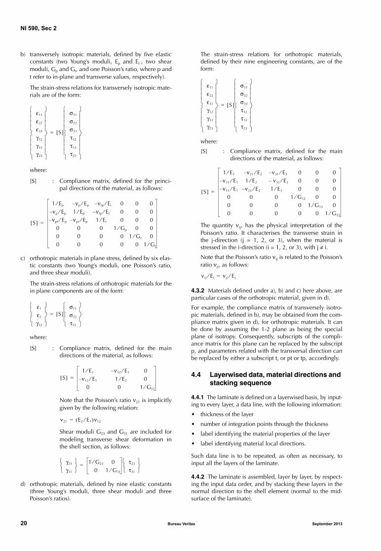
• transversely isotropic materials, defined by five elastic constants (two Young’s moduli, two shear moduli, and one Poisson’s ratio, identified by indices p and t, refer-ring to in-plane and transverse values, respectively)
• orthotropic materials in plane stress, defined by six elas-tic constants (two Young’s moduli, one Poisson’s ratio, and three shear moduli)
• orthotropic materials, defined by nine elastic constants (three Young’s moduli, three shear moduli and three Poisson’s ratio)
• generally orthotropic materials, obtained by a rotation of Θ3 degrees about the third axis of a fully orthotropic material (see [6.4])
• anisotropic materials, defined by twenty one indepen-dent constants (see [6.3]).
2.3.2 Structural mechanical properties of composite mate-rials are input in terms of:
• either layerwised material properties
• or equivalent material properties, valid for the whole thickness of the material.
2.3.3 Depending on the size of the FE model, the second option here above can be adopted, for a first global calcula-tion, of the entire structure. In any case, there will always be a compromise of adapting the model mesh generation to the more suitable approach for the definition of non isotro-pic materials.
2.3.4 For structures having complex geometries, the adop-tion of ‘homogeneous equivalent’ material-approach may require several definitions of ‘equivalent materials’, on a zone by zone basis, keeping in mind the influence of ‘local’ geometries on the real material fibres orientation.
2.3.5 In case of using equivalent material definitions, results from this global analysis are to be considered as the input data of a second analysis. This second analysis could cover, for example, a limited region of the previous model, by adopting a layerwised approach for the input of material mechanical properties.
2.4 Material local directions
2.4.1 In case of orthotropic materials, definition of local material axes are required to input the material mechanical properties.
2.4.2 Cylindrical system of axes may be adopted to define material local directions for FE models regarding the com-posite rudder stock.
2.4.3 In case of FE models with 3D solid continuum ele-ments, generated by revolution of an axisymmetric model around its longitudinal axis of symmetry, a subroutine may be adopted to define material local axes for all elements of the model (see [6.6]).
2.5 Boundary conditions
2.5.1 Two general categories of FE models are considered with regards to boundary conditions:
• axisymmetric models, with contact (axisymmetric geometry and axisymmetric loads)
• 3D models, with contact (axisymmetric geometry and either, axisymmetric loads or non-axisymmetric loads).
2.5.2 In case of models covering the entire structure of the CRS, boundary conditions are applied to nodes related with supports in way of pintle bearings, or rudder bearings, or steering gear. Some additional nodes, or degrees of freedom may be constrained, to avoid singular behaviour of the structure, related with rigid body motions.
2.5.3 Models dedicated to the cone coupling assembly require specific boundary conditions, for each representa-tive step of the assembly process. This will be described for each type of model considered inside of this Guidance Note.
2.5.4 In this Guidance Note, 3D models may also be refer-ring to models defined with either beam elements or shell section elements, submitted to both bending and torsion efforts. These models may have three degrees of freedom in translation and three others in rotation.
2.5.5 For the direct calculations of the CRS, FE models based on either beam elements or shell section elements are, in general, to be adopted for preliminary analyses. In any case, the validity of these models are, of course, to be considered by associating the complexity of the structural part (the CRS), with the capability of these elements to suit-ably model the behaviour of the structure.
16 Bureau Veritas September 2013

NI 590, Sec 2
2.6 Loading cases
2.6.1 Two general categories of FE models are considered with regards to loading cases:
• Those referring to global (and detailed) design of the CRS, which ones consider both torsion and bending effects produced by the rudder force acting on the rud-der blade
• FE models dedicated to the cone coupling assembly process, which first consider forces acting during the assembly process, and then evaluate the capacity of the conical joint to withstand either torsion or bending, sep-arately, or both, bending and torsion together.
2.6.2 Load cases for FE analyses of the entire rudder stock are chosen in accordance with Sec 1, [3.1]. In case of the cone coupling assembly process, different steps are defined in accordance with Sec 1, [6.2].
2.7 Stress failure criteria
2.7.1 Unidirectional and quadratic failure criteria are con-sidered in terms of stresses acting on the composite material.
2.7.2 Failure criteria output variables are to be selected for the specifc regions of the FE model, before running the FE analysis.
2.8 Other aspects
2.8.1 Contact surfaces are used to represent the interation between:
• The CRS and support(s), in way of bearings, for models representing the whole structure of the stock
• The outer surface of the stock tapered region and the inner surface of the hub (the massive part), for models dedicated to the cone coupling assembly-process.
2.8.2 Friction coefficient in case of contact between steel surfaces, is taken:
• either equal to 0,025, when there is a presence of oil between steel surfaces of the rudder stock and the hub (oil hydraulic pressure during the cone coupling assembly)
• or equal to 0,13, when the contact occurs between two steel surfaces, after removing the oil.
3 Global calculations with composite beam sections
3.1 General
3.1.1 This is a procedure for analysing and postprocessing a beam model using tailor-made meshed cross-section(s). The beam cross-section may have an arbitrary shape, and may include multiple materials, multiple cells, and non structural mass.
This procedure may be summarised, as follows:
a) Mesh generation and launch of 2D analysis(es) of FE model(s) representative of one or more ‘composite’ beam cross-section(s)
b) Use of the generated cross-sectional properties to run a subsequent FE beam analysis
c) Use the beam analysis results to postprocess the stored output from either the beam model or the 2D cross-sec-tion model(s).
3.2 Methodology
3.2.1 The CRS is split up into a minimum number of repre-sentative regions, by considering representative composite beam cross-section for every region.
3.2.2 For the adopted circular shapes of cross-sections, the composite cross-sections may contain one, two or more concentric rings of materials.
3.2.3 Every beam cross-section is to be associated with the following data:
• Its initial axial-position and the span length for which mechanical properties of the section are kept constant
• detail of concentric regions of materials, which consti-tute the composite cross-section (inner and outer radius of each material-region, mesh discretisation-parameter, material properties, including the density, for each material concentric-region (for the calculation of inertial properties, if necessary).
3.2.4 Based upon these data, a 2D mesh generation is pro-duced for the material concentric-regions, containing all relevant material properties of relevant ‘material-regions’ of the ‘composite ‘ beam cross-section, as illustrated in Fig 1.
Figure 1 : Composite beam cross-section
September 2013 Bureau Veritas 17

NI 590, Sec 2
3.2.5 These operations are repeated for every ‘composite’ beam cross-section. Following this procedure, mechanical properties for every representative ‘composite’ beam cross-section are calculated. They may be then used in a subse-quent FE analysis, based on Timoshenko beam elements.
3.2.6 To summarise, two types of FE analyses are required to perform the ‘global’ calculations with composite beam sections. They are identified, as follows:
• Composite beam cross-sections analyses (2D analyses)
• Beam section analysis with composite cross-sections, calculated in the previous analyses (3D analysis).
3.3 Composite beam cross-sections analyses
3.3.1 Two types of materials may be used for the definition of the material mechanical properties, as follows:
• isotropic material, defined by the Young’s modulus, E, and the shear modulus, G
• orthotropic shear properties material, defined by shear moduli G1 and G2 given in two perpendicular directions of the beam cross-section, and the Young’s modulus, E, in the axial direction of the beam.
3.3.2 The stress-strain relationship for above materials in the beam cross-section axis is, as follows:
In the above expression, σ11 corresponds to the beam’s axial stress, and τ21 and τ31 represent two shear stresses.
3.3.3 For an isotropic material, the stiffness matrix, [R], is defined, as follows:
3.3.4 For the orthotropic ‘shear properties’ material, the stiffness matrix, [R], is the following:
where the angle α is a user-defined material orientation, to be defined with relation to the local axes of the beam section.
3.3.5 Results from each composite beam cross-section analyses may be output at particular integration points, selected on the cross-section.
Cross-sectional property information, calculated per com-posite cross-section, will be recovered for the subsequent beam section analysis, as described in [3.4].
3.4 Beam section analysis with composite cross-sections
3.4.1 FE analysis based on composite cross-sections prop-erties, calculated from [3.3], is performed with Timoshenko beam theory. Global stiffness of the CRS section along the axial direction can be represented by a suitable split up of the structure.
3.4.2 Definition of tapered beam section elements may be used for the transition regions of the model, to smoothly change the dimensions from one meshed cross-section span to the subsequent one.
3.4.3 Inner surface of either the pintle bearing or stock bearing, for easiness of modeling, may be represented by rigid body surfaces, attached to a ‘reference’ node. This node may be connected to spring elements, with stiffness properties calculated in order to reproduce the stiffness of the support.
3.4.4 Special care is to be taken for the definition of con-tact interactions between the outer surface of the CRS and the inner surface of pintle bearing(s) or stock bearing(s). As ‘composite’ beam sections may have arbitrary shapes and dimensions, the user has to indicate the part of contact sur-faces that should be tied one to the other, before starting the analysis. This may represent a limitation of using this type of FE model.
3.4.5 Laboratory mechanical test-results, if available, may be compared to displacements and rotations results obtained from FE analysis, in view of validating the model.
3.4.6 Several trials may be required before the obtainance of good correlation between test-results and FE results. The user may have to progressivelly adapt the percentage of conctat surfaces to be ‘tied’, before obtaining good fittings, in terms of deformed shapes obtained from tests and FE analyses, as illustrated in Fig 2.
4 Global calculations with composite shell sections
4.1 General
4.1.1 Two basic approaches may be considered to model the CRS with shell elements, as follows:
• With conventional shell elements, for which the geome-try is specified at the reference surface, and the thick-ness is given by section property. In this case, nodes may have displacement and rotation degrees of freedom
• With continuum shell elements, for which full 3D geometry is specified, and element thickness is defined by nodal geometry. In this case, nodes may only have displacement degrees of freedom.
σ11
τ21
τ31
R[ ]e11
γ21
γ31
=
R[ ]E 0 0 G
sym G
=
R[ ]E 0 0
G1 αcos( )2 G2 αsin( )2+ G1 G2–( ) αcos αsin
sym G1 αsin( )2 G2 αcos( )2+
=
18 Bureau Veritas September 2013

NI 590, Sec 2
Figure 2 : Trials with % of contact-surface
4.1.2 Only FE analysis of the entire model, based on ‘con-ventional’ shell elements theory are described inside of this Guidance Note.
4.1.3 The mesh generation in case of FE model with contin-uum shell elements is quite similar to that one of 3D solid continuum elements. FE calculations with continuum shell elements are based on shell theory, while calculations with 3D solid elements are based on solid continuum elements theory.
4.2 Mesh generation for conventional shell elements
4.2.1 The mesh generation is made for the mid-section sur-face of the structure, and the mechanical properties of the shell section are defined by:
• either giving multi-layered material properties, to be sequentially stacked following the normal direction of the shell surface
• or by giving material properties of an equivalent mate-rial, followed by the thickness of the shell.
4.2.2 The CRS can be associated to a multi-layered com-posite structure, made of several layers of CFRP (Carbon Fibre Reinforced Plastic), and reinforced by steel liner and steel insert.
4.2.3 For this kind of multi-layered composite structure, only the FE modeling based on the definition of several lay-ers of materials is considered, in the scope of this Guidance Note.
4.2.4 The FE mesh generation is based on either general-purpose or thick shell elements, as they are suitable to model the behaviour of thick structures like the CRS. Gen-
eral-purpose elements may use either thin or thick shell-ele-ment theory, depending on the ‘thickness aspect ratio’ of the structure.
4.2.5 The CRS is to be split up into representative ‘shell-section-regions’, along of the axial direction of the CRS, by considering representative material components necessary for the shell section definition. The choice of the stacking sequence needed for the definition of the stiffness properties of the section, especially for regions containing multiple materials, with variable ticknesses, represents a major task for the definition of the right stiffness of the shell section.
4.2.6 Nodal thickness data may be given to introduce ‘tapered’ thickness of the shell. The use of particular mate-rial, with very low mechanical properties, may be adopted as a trick, to place, for example, the first and the last layers of the composite at the right locations, as per the mid-thick-ness surface.
4.2.7 Based on data given for all representative ‘shell-sec-tion-regions, the equivalent stiffness matrix of the model is calculated by the FE code. The FE analysis will first calcu-late forces, displacements and rotations of the nodes, at the mid-section surface of the model. Based on these results, stresses, strains, and other variables may be calculated at previously selected locations through the thickness of the section.
4.3 Material properties for conventional shell elements
4.3.1 For the definition of the material mechanical proper-ties four types of elastic materials may be used, as follows:
a) isotropic material, defined by the Young’s modulus, E, and the shear modulus, G (see [3.3])
September 2013 Bureau Veritas 19
NI 590, Sec 2
b) transversely isotropic materials, defined by five elastic constants (two Young’s moduli, Ep and Et , two shear moduli, Gp and Gt, and one Poisson’s ratio, where p and t refer to in-plane and transverse values, respectively).
The strain-stress relations for transversely isotropic mate-rials are of the form:
where:
[S] : Compliance matrix, defined for the princi-pal directions of the material, as follows:
c) orthotropic materials in plane stress, defined by six elas-tic constants (two Young’s moduli, one Poisson’s ratio, and three shear moduli).
The strain-stress relations of orthotropic materials for the in plane components are of the form:
where:
[S] : Compliance matrix, defined for the main directions of the material, as follows:
Note that the Poisson’s ratio ν21 is implicitly given by the following relation:
Shear moduli G23 and G31 are included for modeling transverse shear deformation in the shell section, as follows:
d) orthotropic materials, defined by nine elastic constants (three Young’s moduli, three shear moduli and three Poisson’s ratios).
The strain-stress relations for orthotropic materials, defined by their nine engineering constants, are of the form:
where:
[S] : Compliance matrix, defined for the main directions of the material, as follows:
The quantity νij, has the physical interpretation of the Poisson’s ratio. It characterises the transverse strain in the j-direction (j = 1, 2, or 3), when the material is stressed in the i-direction (i = 1, 2, or 3), with j ≠ i.
Note that the Poisson’s ratio νij is related to the Poisson’s ratio νji, as follows:
4.3.2 Materials defined under a), b) and c) here above, are particular cases of the orthotropic material, given in d).
For example, the compliance matrix of transversely isotro-pic materials, defined in b), may be obtained from the com-pliance matrix given in d), for orthotropic materials. It can be done by assuming the 1-2 plane as being the special plane of isotropy. Consequently, subscripts of the compli-ance matrix for this plane can be replaced by the subscript p, and parameters related with the transversal direction can be replaced by either a subscript t, or pt or tp, accordingly.
4.4 Layerwised data, material directions and stacking sequence
4.4.1 The laminate is defined on a layerwised basis, by input-ing to every layer, a data line, with the following information:
• thickness of the layer
• number of integration points through the thickness
• label identifying the material properties of the layer
• label identifying material local directions.
Such data line is to be repeated, as often as necessary, to input all the layers of the laminate.
4.4.2 The laminate is assembled, layer by layer, by respect-ing the input data order, and by stacking these layers in the normal direction to the shell element (normal to the mid-surface of the laminate).
ε11
ε22
ε33
γ12
γ13
γ23
S[ ]
σ11
σ22
σ33
τ12
τ13
τ23
=
S[ ]
1 Ep⁄ ν– p Ep⁄ ν– tp Et⁄ 0 0 0ν– p Ep⁄ 1 Ep⁄ ν– tp Et⁄ 0 0 0ν– pt Ep⁄ ν– pt Ep⁄ 1 Et⁄ 0 0 0
0 0 0 1 Gp⁄ 0 00 0 0 0 1 Gt⁄ 00 0 0 0 0 1 Gt⁄
=
ε1
ε2
γ12
S[ ]σ11
σ22
τ12
=
S[ ]1 E1⁄ ν– 12 E1⁄ 0ν– 12 E1⁄ 1 E2⁄ 0
0 0 1 G12⁄
=
ν21 E2 E1⁄( )ν12=
γ23
γ31 1 G23⁄ 0
0 1 G31⁄τ23
τ31
=
ε11
ε22
ε33
γ12
γ13
γ23
S[ ]
σ11
σ22
σ33
τ12
τ13
τ23
=
S[ ]
1 E1⁄ ν– 21 E2⁄ ν– 31 E3⁄ 0 0 0ν– 12 E1⁄ 1 E2⁄ ν– 32 E3⁄ 0 0 0ν– 13 E1⁄ ν– 23 E2⁄ 1 E3⁄ 0 0 0
0 0 0 1 G12⁄ 0 00 0 0 0 1 G13⁄ 00 0 0 0 0 1 G23⁄
=
νij Ei⁄ νji Ej⁄=
20 Bureau Veritas September 2013

NI 590, Sec 2
4.4.3 By default, half of the total thickness of all input lay-ers is placed upwards of the mid-section of the laminate and other half downwards.
4.4.4 The local material directions for the CRS may be defined based on a cylindrical co-ordinate system of axes, as this structural part has an axisymmetric geometry (1rst axis = radial direction; 2nd axis = circumferential direction; and 3rd axis = axial direction). For any point of the CRS structure, material local axes may be defined, by just adjust-ing fibre direction-axes with regards to the ‘cylindrical refer-ence-axes’ (for example, by making a rotation of α degrees around the radial direction).
4.4.5 All these data are to be dully checked by using a graphic pre-processor tool, to make sure that the material directions, for every layer of material, are consistent with the model geometry.
4.5 Contact in way of pintle bearings and stock bearings
4.5.1 Inner surface of either the pintle bearing or stock bearing, for easiness of modeling, may be represented by rigid body surfaces, attached to a ‘reference’ node. This node may be connected to spring elements, with stiffness properties calculated in order to reproduce the stiffness of the trunk.
4.5.2 The stiffness properties of the supports, in way of pin-tle bearing(s) or stock bearing(s), may also be calculated directly by FE analysis, by including these areas as part of the FE model.
4.5.3 To minimize convergence problems when dealing with contact, it is recommended to start the analysis with ‘specially’ stable boundary conditions and a low percent-age of the actual load, just in view of establishing an initial contact between surfaces. A further step should be added to stabilise contact conditions, by adjusting, for example, the boundary conditions to those required for the FE analysis.
4.5.4 History or field output variables may be requested by the user before starting the FE analysis. These variables will permit to obtain output results at intended locations, in terms of, for example: displacements, rotations, contact variable, strain and stress components, reaction forces and moments, failure criteria, etc....
4.5.5 Laboratory mechanical test-results, if available, may be compared to displacements and rotations results obtained from FE analysis, in view of validating the model.
Several trials may be required before the obtainance of good correlation between test-results and FE results.
4.5.6 Eventhough, an FE model with shell elements is defined based on 3D co-ordinates of nodes, it is to keep in mind that shell elements theory remains a 2D approach. FE model is calculated for the mid-surface of the shell, in terms of forces, displacements and rotations at nodes, and then, any requested output variables are extrapolated from these results, based on the shell element-theory, for the selected type of element.
5 Cone coupling with composite axisymmetric elements
5.1 General
5.1.1 FE analysis based on 2D axisymmetric assumption is a simple way to simulate the overall process of the cone coupling assembly of the rudder stock to the hub, by using a hydraulic arrangement.
5.1.2 The efficiency of this conical joint is ensured by the friction forces, generated between contact surfaces of the rudder stock and the hub, during the assembly process.
5.1.3 Key parameters controlling the efficiency of the cone coupling joints, are mainly: contact pressure, percentage of the real contact surface, friction coefficient and tapering in the area of contact.
5.1.4 Design values of these generated friction forces, in accordance with Sec 1, [6.2.1] b), are calculated based on:
a) the minimum contact pressure required to withstand the biggest of the two efforts:
1) either two times the torque produced by the rudder force
2) or the axial stress caused by the bending moment in the way of the cone coupling
b) the maximum pressure on the inner surface of the hub, to avoid any damage of this part.
5.1.5 In case of the CRS, multiple regions made of different materials may exist inside of the piece, in the way of the cone coupling assembly area. For the design concept shown in Sec 1, Fig 2, main components of the stock are idenfied, as follows:
• a metallic insert (to withstand radial stresses)
• a composite rudder shaft
• a liner (to avoid direct contact of the composite with the steel hub, during the assembly process).
5.1.6 The stiffness of the CRS cross-sections may vary along the axial direction of the structure, especially in the region of the cone coupling joint, due to the presence of multiple regions of materials, with variable cross-sections dimen-sions.
For this reason, the designed values of push-up lengths, as defined in NR467, Pt B, Ch 10, Sec 1 for a steel rudder stock, have to be corrected to take into account the real cross-sections stiffnesses along the axial direction of the structure.
5.1.7 FE axisymmetric analysis may be used to find the cor-rected value of push-up length, necessary to generate the rule contact-pressure between the hub and the rudder stock. This average value of pressure is to produce friction forces capable to withstand rules values of bending and tor-sion moments.
5.1.8 This type of FE analysis may also give an appraisal of stresses and strains generated inside of the CRS during the cone coupling assembly process.
September 2013 Bureau Veritas 21

NI 590, Sec 2
5.2 The FE axisymmetric model
5.2.1 A 2D longitudinal cut of the rudder stock and the hub is considered for the generation of two separate parts, that will be put in contact during the cone coupling assembly process.
This process may be assumed as axisymmetric, as the geom-etry of both parts and relevant loads are axisymmetric. The FE model is generated with 4-nodes axisymmetric elements, with twist, to leave the possibility of testing the conical joint against torsion efforts.
5.2.2 Material properties are to be input in the three main directions of the model, ie, in radial, circumferential and axial directions. A calculation of an equivalent material, in case of multi-layered laminates, may be necessary, to make it possible.
5.2.3 The cone coupling assembly process is split up into four main steps, as follows:
a) STEP 1: application of a hydraulic pressure acting between contact surfaces (increase of the gap between the outer surface of the stock and the inner surface of the hub)
b) STEP 2: imposing relative movement between contact surfaces, by considering a friction coefficient of 0.025, and to attain the total relative movement equal to the designed ‘push-up length’.
During this STEP, the hydraulic pressure is maintained between contact surfaces.
c) STEP 3: removal of the hydraulic pressure, but keeping the push-up force and changing the friction coefficient to 0.13 (simulation of contact between two steel sur-faces, without the presence of oil on the surfaces)
d) STEP 4: removal of the push-up force, but keeping fric-tion forces, with a friction coefficient of 0,13.
Schematic views of the cone coupling assembly process, pointing out its 4 STEPS, are given in Fig 3 and Fig 4.
Figure 3 : Cone coupling assembly process
5.2.4 FE analysis-results may be given, for example, in terms of contact pressure calculated along the tapered sur-faces of contact, at the end of STEPS 2, 3 and 4.
5.2.5 These 4-STEPS calculations are to be performed for ‘tentative’ values of push-up length, until to find, at the end of the STEP 4, average values of the contact pressure being in conformance with those of Sec 1, [6.2.1] b).
5.2.6 At the end of each of these 4-STEPS, it can be evalu-ated the level of stresses acting on different areas of the CRS. In case of multi-layered materials, defined by an equivalent material, a subsequent calculation is to be per-formed, to recover stresses and strain acting in different lay-ers of the material.
Special care is to be drawn during the mesh generation of the 2D model, in such way to make possible these subse-quent calculations in case of multilayered materials. Areas of the 2D FE model considered for the subsequent calcula-tions are to be represented on a 3D basis model, to be mod-eled on a layerwised approach, and loaded with displacement values recovered from the 2D analysis.
A simplified FE model may be built to demonstrate the expected equivalent behaviours of both model approaches.
Figure 4 : Four steps of the cone coupling numerical simulation
STEP 1Hydraulic pressure
STEP 2Pressure + push-up force
STEP 3Push-up & friction forces
STEP 4Friction force
Tota
l pus
h-up
leng
th
22 Bureau Veritas September 2013

NI 590, Sec 2
5.2.7 The definition of ‘an equivalent’ material to dully rep-resent the multilayered composite material remains a chal-lenge and maybe a limitation of using an axisymmetric approach, especially for the evaluation of strain-stresses lev-els inside of the composite.
6 FE models with 3D solid elements
6.1 General
6.1.1 This is the most appropriate way to analyse the struc-tural behaviour of the composite rudder stock, especially for structures involving several materials, and with complex geometries.
6.1.2 The use of 3D solid elements is based on the repre-sentation of the full 3D geometry of the part, and assumes a 3D approach for the element formulation. It will allow a bet-ter definition of material properties, in case of non isotropic material, especially for areas of geometrical complexity.
It requires big computer capabilities to handle very large models, with:
• non linear problems, involving contact between:
- two steel surfaces, in way of the cone coupling assembly joint (hub and CRS)
- two surfaces, in way of the neck bearing (CRS and neck bearing)
• the use of non linear geometry approach (large displace-ments theory)
• multi-layered orthotropic materials, or more complex material types (monoclinic, with one plane of material property symmetry, or totally anisotropic, for which no plane of symmetry exists)
• multiple materials, such as, steel, epoxy, glass fibre and carbon fibre reinforced plastics (GFRP and CFRP, respectively).
6.1.3 Materials used on the manufacturing of composite rudder stocks are, in general, of orthotropic type.
6.1.4 The FE model may contain very thin regions of ele-ments, representing, for example, bonded glue areas, or areas made with thin layers of glass fibre reinforced plastics, designed to join a material region made of composites to a region made of steel. These thin layers are placed between these 2-materials to avoid galvanic corrosion of the steel caused by the carbon fibres.
6.1.5 To keep the size of the FE model within reasonable values, the use of mixed ‘element’ types, as mentioned on [2.1.1] may be suitable, especially for areas of the model for which only the stiffness of the structure is to be reproduced, as they would be submitted to lower stress-values.
6.1.6 In case of monoclinic or totally anisotropic materials, all relevant terms of the compliance (or of the stiffness) matrix are to be input to the FE analysis. If required, a sim-plified FE model could be defined in view of validating the terms of an ‘equivalent’, or several ‘equivalent anisotropic’ material(s) matrix(ces).
6.1.7 Multi-layered composite 3D elements are in general only used in case of hexahedric elements (8-nodes, or more, brick elements). Two opposite faces of the element are used to define the three possible stacking directions, to constitute the multi-layered composite.
6.1.8 In case of complex geometries, with variation of shapes, the definition of local material directions may require the adoption of a ‘user subroutine’, completely inte-grated by the FE code. This subroutine may, for example, define material-directions for each relevant element of the model, based on its geometrical properties, as explained in [6.6].
6.1.9 In any case, when dealing with very complex struc-tures, involving multiple geometries and materials, a cus-tomised mesh generation is to be considered, on a case by case basis.
6.2 From 2D axisymmetric to 3D solid elements
6.2.1 The 3D FE model is obtained from the 2D FE axisym-metric model described under [5], by making a revolution of this axisymmetric plan around its longitudinal axis of symmetry, over an angle of 360 degrees. This generates 3D solid continuum elements.
6.2.2 The following aspects are to be considered for the 3D model-generation:
a) Number of elementary slices required to generate 3D mesh over 360 degrees. The rotation angle used to define a slice must be quite small to respect the geometrical ratio between isoparametric sides of the element, but not too small, to keep the size of the model reasonable.
b) Contact difficulties arising when dealing with circumfer-ential surfaces generated for 3D solid continuum ele-ments. Outer surfaces of two adjacent slices may produce conflicting areas for the definition of surface-normals.
c) Selection of the stack direction suitable for the defini-tion of multi-layered composites.
d) For the chosen stack direction, make sure that mesh sizes in the region of the composite are consistent with thicknesses of different layers of the laminate.
e) Take the advantage of a 3D model generated by the rev-olution of an axisymmetric model around its axis of symmetry, to define customised material local directions for the multi-layered composites.
6.2.3 Compliance and stiffness matrices of this guidance have been defined in the main directions of the material. The transfer of theses properties to the global axes of the model is made directely by the FE code, based on material local directions, to be defined for every non isotropic mate-rial of the model.
6.2.4 Transformation equations for stress or strain tensors and compliance and stiffness tensors, as well, are briefly presented under [6.4].
September 2013 Bureau Veritas 23

NI 590, Sec 2
Reference to these transformation equations is made in[6.7] for calculating terms of the stiffness (or compliance) matrix of an equivalent material, in view of replacing the layerwised laminate of certain regions of the model.
These equations are used to extend the laminate calcula-tion-methodology, described in NR546, Section 6, for the use of more complex material properties (fully orthotropic or more).
6.2.5 In general, FE codes are able to deal directely with layerwised approach, and before starting the analysis they calculate, element by element, the equivalent stiffness (or compliance) matrices, that will be used to constitute the global stiffness matrix of the structural model.
6.2.6 Depending on the geometry of the structure, and on its complexity, the use of ‘equivalent’ material(s), may allow a big reduction of the FE model size. This kind of choice is not always possible, and should be considered on a case by case basis.
6.3 Material properties for 3D solid continuum elements
6.3.1 In addition to materials defined or referred to in [4.3], 3D solid continuum elements may be also associated to anisotropic materials defined, as follows:
where:
[S] : Compliance matrix, defined in terms of engi-neering constants, as follows:
6.3.2 Additional engineering constants, as compared with those used for orthotropic materials, are introduced for the definition of the Spq terms of the compliance matrix, [S], with p, q = 1, 2, .., 6, as follows:
a) Generalisations of Poisson’s ratios: ηk, ij
with:
• k = 1, 2, or 3, and
• i, j = 1, 2, or 3, and
• i ≠ j
used for the definition of S14, S15, S16, S24, S25, S26, S34, S35, and S36
ηk, ij : Coefficients of interaction (or mutual influ-ence) of the first kind. They refer to normal components of strains generated by shear stresses
b) Generalisations of Poisson’s ratios: ηij, k
with:
• k = 1, 2, or 3, and
• i, j = 1, 2, or 3, and
• i ≠ j
used for the definition of S41, S42, S43, S51, S52, S53, S61, S62, and S63
ηij, k : Coefficients of interaction (or mutual influ-ence) of the second kind. They refer to shear components of strains generated by normal stresses.
c) Coefficients μij, kl
with:
• i, j = 1, 2, or 3, and
• k, l = 1, 2, or 3, and
• i ≠ j, k ≠ l, and
• ij ≠ kl
used for the definition of S45, S46, S54, S56, S64, and S65. They refer to shear components of strains generated by ‘noncorresponding’ shear stresses.
μij, kl : Chentsov’s coefficients of interaction. They refer to shear components of strains gener-ated by ‘non-corresponding’ shear stresses.
6.3.3 It can be demonstrated that the compliance matrix, [S], is symmetrical, and that the following relations are valid:
6.3.4 Taking into consideration its symmetry, the compli-ance matrix of an anisotropic material requires the defini-tion of 21 independent terms.
ε11
ε22
ε33
γ12
γ13
γ23
S[ ]
σ11
σ22
σ33
τ12
τ13
τ23
=
S[ ]
1E1
----- ν– 21
E2
-------------- ν– 31
E3
-------------- η1 12,
G12
---------- η1 13,
G13
---------- η1 23,
G23
----------
ν– 12
E1
---------- 1E2
----- ν– 32
E3
---------------- η2 12,
G12
---------- η2 13,
G13
---------- η2 23,
G23
----------
ν– 13
E1
---------- ν– 23
E2
---------- 1E3
----- η3 12,
G12
---------- η3 13,
G13
---------- η3 23,
G23
----------
η12 1,
E1
---------- η12 2,
E2
---------- η12 3,
E3
---------- 1G12
-------- μ12 13,
G13
------------ μ12 23,
G23
------------
η13 1,
E1
---------- η13 2,
E2
---------- η13 3,
E3
---------- μ13 12,
G12
------------ 1G13
-------- μ13 23,
G23
------------
η23 1,
E1
---------- η23 2,
E2
---------- η23 3,
E3
---------- μ23 12,
G12
------------ μ23 13,
G13
------------ 1G23
--------
=νij
Ei
----- νji
Ej
-----=
ηk ij,
Gij
-------- ηij k,
Ek
--------=
μi j kl,
Gkl
---------- μkl ij,
Gij
----------=
24 Bureau Veritas September 2013

NI 590, Sec 2
6.4 Transformation equations for stress/strain and compliance/stiffness tensors
6.4.1 Stress and strain are second rank tensors, while com-pliance and stiffness are fourth rank tensors.
6.4.2 Transformation equations for 2nd and 4th rank ten-sors, are respectively expressed in a tensor notation, as fol-lows:
• T’ij = aik ajf Tkf
• T’ijkf = aim ajn ako afp Tmnop
where T’ contain the transformed components of T. The “a”s terms are direction cosines of the new transformed coordi-nate system relative to the original coordinate system. The number of indices corresponds to the tensorial rank.
6.4.3 Transformations made by dextral rotations of an angle Θ3 about the X3 axis for materials defined in their principal axes, X1 , X2 , X3 , may be expressed, as listed below.
Note 1: The terms “dextral” and “right-handed rotation” have the same meaning, and are both used inside of this Guidance Note.
a) For the stress-tensor transformation:
This equation can be expressed symbolically by:
where the transformation matrix is given, as follows:
where:
n = sin Θ3
m = cos Θ3
b) For the strain-tensor transformation:
This equation can be expressed symbolically by:
where the transformation matrix is given, as follows:
Relations between transformation matrices for the stress and strain tensors are as follows:
where [Tvalue]-1 and [Tvalue]T represent, respectively, the inverse and the transpose of the transformation matrix.
c) For the stiffness-tensor transformation, the following equations apply:
where:
[R] : Symbolic form of the stiffness tensor
[R’] : Symbolic form of the transformed stiffness-tensor, obtained by the dextral rotation
d) For the compliance-tensor transformation, the following equations apply:
where:
[S] : Symbolic form of the compliance tensor
[S’] : Symbolic form of the transformed compli-ance-tensor, obtained by a right-handed rotation around the third material axis.
6.4.4 The equation given in [6.4.3], d), is used to calculate the transformed compliance matrix, [S’], obtained by a right-handed rotation of Θ3 degrees about the third axis of a fully orthotropic material, initially defined for their principal material axes.
6.4.5 After this transformation, the obtained compliance matrix, [S’], will have 8 additional non-zero terms, as com-pared with the fully orthotropic matrix, defined in [4.3.1], d). The [S’] matrix is given by:
σ1 ′1′
σ2 ′2′
σ3 ′3′
τ1′2 ′
τ1′3 ′
τ2′3 ′
Tσ Θ3( )[ ]
σ11
σ22
σ33
τ12
τ13
τ23
=
σ′{ } Tσ Θ3( )[ ] σ{ }=
Tσ Θ3( )[ ]
m2 n2 0 2nm 0 0
n2 m2 0 2nm– 0 00 0 1 0 0 0
nm– nm 0 m2 n2– 0 00 0 0 0 m n0 0 0 0 n– m
=
ε1 ′1′
ε2 ′2′
ε3 ′3′
γ1 ′2′
γ1 ′3′
γ2 ′3′
Tε Θ3( )[ ]
ε11
ε22
ε33
γ12
γ13
γ23
=
ε′{ } Tε Θ3( )[ ] ε{ }=
Tε Θ3( )[ ]
m2 n2 0 nm 0 0
n2 m2 0 nm– 0 00 0 1 0 0 0
2nm– 2nm 0 m2 n2– 0 00 0 0 0 m n0 0 0 0 n– m
=
Tε Θ3( )[ ]T Tσ Θ3( )[ ] 1– Tσ Θ3–( )[ ]= =
Tε Θ3( )[ ] 1– Tε Θ– 3( )[ ] Tσ Θ3( )[ ]T= =
R′[ ] Tσ[ ] R[ ] Tε[ ] 1–=
R[ ] Tσ[ ] 1– R′[ ] Tε[ ]=
S ′[ ] Tε[ ] S[ ] Tσ[ ] 1–=
S[ ] Tε[ ] 1– S′[ ] Tσ[ ]=
S′[ ]
1E1 ′------ ν– 2′1 ′
E2 ′---------------- ν– 3'1''
E3''----------------
η1'' 1 ′2′,
G1 ′2 ′-------------- 0 0
ν– 1 ′2′
E1 ′------------- 1
E2 ′------ ν– 3 ′2 ′
E3 ′-------------------
η2 ′ 1′2 ′,
G1 ′2 ′-------------- 0 0
ν– 1 ′3′
E1 ′------------- ν– 2′3 ′
E2 ′------------- 1
E3 ′------
η3 ′ 1 ′2′,
G1 ′2′-------------- 0 0
η1 ′2′ 1 ′,
E1 ′--------------
η1 ′2 ′ 2′,
E2 ′--------------
η1 ′2′ 3 ′,
E3 ′-------------- 1
G1 ′2′----------- 0 0
0 0 0 0 1G1 ′3′----------- μ1 ′3′ 2 ′3′,
G2′3 ′-----------------
0 0 0 0 μ2 ′3′ 1 ′3′,
G1′3 ′----------------- 1
G2′3 ′-----------
=
September 2013 Bureau Veritas 25

NI 590, Sec 2
6.4.6 A material represented by this transformed compli-ance matrix is referred to generally orthotropic, to distin-guish it from an anisotropic material.
6.4.7 The non-zero components of matrix [S’], may be expressed row by row, in terms of Si’j’ , i’, j’ = 1, 2, .., 6, by considering:
• Engineering constants of the on-axis orthotropic material
• Values of m and n (cosinus and sinus of the rotation angle, Θ3)
6.4.8 The non-zero components of matrix [S’], based on this terminology, would be, for example, expressed by:
And, in general, by Si’j’ .
These Si’j’ terms may be written, as follows:
6.5 Layerwised data for 3D brick elements and stacking direction
6.5.1 FE analysis codes suitable for calculations with com-posites allow the use of composite elements, constituted by several layers of materials, which are stacked in a given direction.
6.5.2 These 3D composite elements must be of hexahedric type, with every two opposite faces of the brick being used for the definition of the three possible stacking directions. The material layers may be stacked in any of the three iso-parametric coordinates, parallel to opposite faces of iso-parametric 8-nodes elements.
6.5.3 The typical 8-nodes brick element of Fig 5 may be used to illustrate these three possible stacking directions, as follows:
• stacking direction 1: defined from face 6 (1-4-8-5) to face 4 (2-6-7-3)
• stacking direction 2: defined from face 3 (1-5-6-2) to face 5 (3-7-8-4)
• stacking direction 3: defined from face 1 (1-2-3-4) to face 2 (5-8-7-6)
6.5.4 Every face of the hexahedric element is defined by its constitutive 4-nodes, in such way to have its normal ori-ented towards the element face.
6.5.5 For the FE model illustrated in Fig 5, the stacking direction 2 is the suitable one, permitting the representation of the multiple filament winding layed up on the surface of the CRS.
6.5.6 The use of 3D composite elements requires the gen-eration of a dedicated mesh, with a dimensional control of 8-nodes brick elements in the stacking direction, which must correspond to a given number of stacked layers of composites.
6.5.7 Material mechanical properties of each layer are to be input, by also indicating the material local directions, and the number of integration points through the thickness of the layer to be considered.
1E1′------ S1 ′1 ′=
ν2′1 ′
E2 ′--------- S1 ′2′=
S1 ′1 ′1E1
----- m4 m2n2 E2
G12
-------- E1
E2
----- 2ν12–
n4E1
E2
-----+ +=
S1 ′2 ′ ν12
E1
-------– m4 n4 m2– n2 1ν12
------- 1E1
E2
----- + E2
G12
--------– E1
E2
-----
+=
S1 ′3 ′ ν13
E1
------- m2 n2ν23
ν13
------- E1
E2
-----+–=
S1 ′4 ′mnE1
-------- m2 n2–[ ] E2
G12
-------- E1
E2
----- 2ν12–
2+ n2 E1
E2
-----⋅ m2– ⋅=
S1 ′5 ′ S1 ′6 ′ 0= =
S2 ′1 ′ S1 ′2 ′=
S2 ′2 ′1E2
----- m4 m2n2 E2
G12
-------- 2ν12E2
E1
-----– n4E2
E1
-----+ +=
S2 ′3 ′ ν23
E2
------- m2 n2ν13
ν23
------- E2
E1
-----+–=
S2 ′4 ′mnE2
-------- n2 m2–[ ] E2
G12
-------- 2ν12E2
E1
-----– 2 m2 n2E2
E1
-----– +=
S2 ′5 ′ S2 ′6 ′ 0= =
S3 ′1 ′ S1 ′3 ′=
S3 ′2 ′ S2 ′3 ′=
S3 ′3 ′1E3
-----=
S3 ′4 ′2mn
E3
------------ E3
E1
----- ν13 2ν23E1
E2
-----– =
S3 ′5 ′ S3 ′6 ′ 0= =
S4 ′1 ′ S1 ′4 ′=
S4 ′2 ′ S2 ′4 ′=
S4′3 ′ S3 ′4′=
S4′4 ′1
G12
-------- 4m2n2G12
E2
-------- E2
E1
----- 1 2ν12
E1
E2
-----+ + m2 n2–( )2+=
S5′5 ′1
G13
-------- m2 n2G13
G23
--------+=
S5′6 ′ S6 ′5′mnG23
-------- 1G23
G13
--------– = =
S6′6 ′1
G23
-------- m2 n2G23
G13
--------+=
26 Bureau Veritas September 2013

NI 590, Sec 2
Figure 5 : Overview of 8-nodes elements generated from the rotation of plane 4-nodes elements
6.6 Material local directions for 3D solids generated by revolution of a 2D model
6.6.1 These particular types of 3D solid meshes, generated by a revolution of a 2D mesh around a symmetry axis of rotation, have particular geometrical properties, that can be used on the definition of material local axes.
For example, if we consider a brick element, with 8 nodes, generated by revolution around a symmetry axis, it can be noticed the following aspects:
a) at least four edges of the element are parallel. (chords of circular arcs, built from the rotation of 4-nodes plane element around the symmetry axis)
b) mid-points of these four edges belong to the same longi-tudinal cut plane, which pass through the symmetry axis of the revolution part
c) elementary-faces of brick elements are formed by 4-nodes, which by geometrical construction, belong to the same plane (4-elementary faces defined by 2-consecu-tive edges referred to in a), 1 elementary-face initially from the 2D model, and the remaining elementary-face obtained by the rotation of the 2D ‘face’)
6.6.2 These geometrical properties may be used directly by the FE code for the calculation, for example, of the material local directions, element by element, for a previously selected region of the model.
6.6.3 For this type of 3D mesh generation, the inner and outer faces of a brick element, defined respectively, by the 2 inner chords of circular arcs, and by 2 outer chords of circu-lar arcs, can be taken as the 2-reference planes used to define material local directions.
6.6.4 The two schematic views of Fig 5 illustrate the emphasized geometrical properties of 3D elements gener-ated by rotation of 4-nodes plane elements. The faces 3 and 5 of the element shown in this figure will define the stacking direction of composite layers.
6.6.5 Mid-points of edges defined by nodes (7-3), (8-4), (5-1), and (6-2) of faces 3 and 5 of this typical element, will define a longitudinal plane passing by the rotation axis of symmetry.
6.6.6 Unit vectors laying on faces 3 and 5 may be defined by the intersections of these planes with the longitudinal plane which passes by the rotation axis of symmetry, and by the mid edge-points.
6.6.7 These geometrical properties may be used for every 8-nodes element of the CFRP material, via a Fortran subrou-tine. This permits customised definition of local directions of fibres, as a function of the specific shape of each 8-nodes element. This approach makes possible to systematically adapt the definition of fibre directions, especially for ele-ments located close to areas of great geometrical variations of the model.
6.6.8 This methodology may be adapted to any FE model generated by the rotation of 4-nodes plane elements around of a symmetry axis.
1
2
3
7
6
5
84
Face 5(3-7-8-4)
Face 4(2-6-7-3)
Face 1(1-2-3-4)
Face 3(1-5-6-2)
Face 6(1-4-8-5)
Face 2(5-8-7-6)
September 2013 Bureau Veritas 27

NI 590, Sec 2
6.7 Equivalent material properties for a lami-nate made of fully orthotropic layers
6.7.1 Equivalent material properties for a laminate may be calculated in analogy with the methodology of NR546, Sec-tion 6, entitled ‘Laminate Characteristics And Panel Analysis For Composite Structure’.This methodology, based on the classical lamination theory (CLT), could be extended to cover other lamina behaviour, adapted, for example, to fully orthotropic materials, or to any other type of material.
The general procedure would be the same, but using suit-able tools to consider the transformation of compliance and / or stiffness tensors, for materials other than orthotropic materials in plane stress.
6.7.2 Transformation equations of an individual k layer of the laminate, given in NR546, Sec 6, [2.1.4], as T and T’, can be replaced by those given in [6.4], as follows:
Transformation equations given in [6.4] are generalisations of those of NR546, Section 6, which were developed for ortho-tropic materials, in plane stress, according to [4.3.1], c). They are only involving a right-handed rotation around the ‘vertical axis of the material.
6.7.3 Depending on the geometrical complexity of the structure, fibres of laminas may not belong to a plane defined by the global system of axes. For these configura-tions, more than a simple right-handed rotation around one axis will be required to express the material matrix in global axes. At the end of these transformations, the equivalent material matrix may look like those of an anisotropic material, con-taining all the 21 independent terms, as illustrated in [6.3].
These transformations are to be performed for all layers of the laminate, to bring them to the same and unique global system of axes.
6.7.4 The resultant forces and moments acting on the lami-nate are to be obtained by integrating stresses in each layer through the thickness of the laminate.
6.7.5 Integration scheme is to be handled by taking into consideration the proper ‘mathematical’ formulation of the stress variation through the stacking direction. This is com-pletely related with the type of element chosen to model the laminate.
6.7.6 The resultant forces and moments, N and M, for all stress components, acting on the n layers shown in NR546, Sec 6, Fig 1, can be expressed, as follows:
6.7.7 The following assumptions are made:
• every k layer is constituted of a fully orthotropic material
• only a simple right-handed rotation around the vertical axis of the material is performed for every k layer.
6.7.8 According to [6.4] a right-handed rotation of Θdegrees around the third axis of an orthotropic material will give a generally orthotropic material.
6.7.9 After a rotation of Θ degrees around its third axis, and adopting the same notation used in NR546, Section 6, the stiffness matrix of any k individual layer expressed in the laminate global axes may be written:
6.7.10 All the terms of the stiffness matrix of any k individ-ual layer of the laminate may be obtained by dextral rota-tion equations given in [6.4]. First calculations will permit to find all the terms of the compliance matrix, [S’]k , of the k layer, by using formulae given for a ‘generally orthotropic’ material.
6.7.11 The stiffness terms of matrix [R]k are obtained from [S’]k, by calculating its inverse, as follows:
6.7.12 For every k layer of the laminate, any Si’j’ term of the compliance matrix, [S’]k, can be calculated based on one or more engineering constants of the fully orthotropic mate-rial, and from the cosinus and sinus of the rotation angle (see transformation equations given in [6.4]).
6.7.13 Equations of resultant forces and moments, N and M, may be written for every k layer of the laminate, and based on the mathematical formulation of the ‘FE element’, these integration formulae may be evaluated through the laminate thickness.
T Tσ Θ– 3( )[ ]↔
T′ Tε Θ– 3( )[ ]↔
NX
NY
NZ
NXY
NXZ
NYZ
σXX
σYY
σZZ
τXY
τXZ
τYZ
k
ZdZk 1–
Zk
k 1=
n
=
MX
MY
MZ
MXY
MXZ
MYZ
σXX
σYY
σZZ
τXY
τXZ
τYZ
k
Z ZdZk 1–
Zk
k 1=
n
=
R[ ]k
R11 R12 R13 R14 0 0R12 R22 R23 R24 0 0R13 R23 R33 R34 0 0
R14 R24 R34 R44 0 0 0 0 0 0 R55 R56
0 0 0 0 R56 R66
=
S′[ ]k
S1 ′1 ′ S1 ′2′ S1′3 ′ S1′4 ′ 0 0S1 ′2 ′ S2 ′2′ S2′3 ′ S2′4 ′ 0 0S1 ′3 ′ S2 ′3′ S3′3 ′ S3′4 ′ 0 0
S1 ′4′ S2 ′4′ S3 ′4 ′ S4′4 ′ 0 0 0 0 0 0 S5′5 ′ S5 ′6 ′
0 0 0 0 S5′6 ′ S6 ′6 ′
=
R[ ]k S′[ ]k1–=
28 Bureau Veritas September 2013

NI 590, Sec 2
6.7.14 For every laminate, the following practical method-ology may be adopted, based on the generation of a simpli-fied FE model, by:
• choosing the suitable type of element
• defining relevant loads and boundary conditions
6.7.15 Output values recovered for one element of the model are to be written in terms of:
• normal and shear strain components through the thick-ness of each layer, for all the layers of the laminate, dully expressed in the global system of axes of the laminate
• resultant values of forces and moments at the element, given for the laminate, in its global system of axes, for relevant components of force and moment
6.7.16 For the implementation of this methodology, the stress tensor is to be previously expressed in terms of the strain-tensor, for every k layer of the laminate, by the follow-ing relation:
Or by replacing the stiffness matrix, as follows:
σ{ }k R[ ]k ε{ }k=
σ{ }k S′[ ]k1– ε{ }k=
September 2013 Bureau Veritas 29

NI 590, Sec 2
30 Bureau Veritas September 2013