rubicon - soundstream amplifier will outperform any other amplifier in the world. t o maximize the...
TRANSCRIPT
1
RUBICON3025021002
Power Amplifiers
Owner’s Manualand
Installation Guide
2000

2
You now own the Soundstream RUBICON amplifier, the product of an un-compromising design and engineering philosophy. Your SoundstreamRUBICON amplifier will outperform any other amplifier in the world.
To Maximize the performance of your system, we recommend that you thor-oughly acquaint yourself with its capabilities and features. Please retain thismanual and your sales receipt for future reference.
Soundstream amplifiers are the result of American innovation and the high-est quality control standards. When properly installed, they will provide youwith many years of listening pleasure. Should your amplifier ever need ser-vice or replacement due to theft, please record the following information whichwill help protect your investment.
Model and Serial #_______________________________
Dealer’s Name__________________________________
Date of Purchase________________________________
Installation Shop_________________________________
Installation Date__________________________________
CAUTION!
Congratulations!
Prolonged listening at high levels may result in hearing loss.Even though your new Soundstream Rubicon amplifiersounds better than anything you’ve ever heard, exercisecaution to prevent hearing damage.
3
Design Features ......................................................................p 4 - 5
Rubicon302 Amplifier Diagram .................................................p 6 - 7
Rubicon502 and 1002 Amplifier Diagrams ................................p 8 - 9
Crossover Adjustments ............................................................p 10
Hawkins Bass Control™ Theory and Use ................................p 11 - 13
Installation: Speaker Output Modes ........................................p 14
Installation: Balanced / Unbalanced Inputs .............................p 15
Installation: Wiring and Diagram .............................................p 16 - 17
Installation: Mounting .............................................................p 18
Installation: Level Setting and Front Spoiler. ...........................p 19
Protection Circuitry and Troubleshooting .................................p 20
Specifications ..........................................................................p 21
Notes ......................................................................................p 22 - 23
Table of Contents

4
♦♦♦♦♦ RUBI™(Rapid-Use Branched Impulse) This new proprietary power sup-ply topology eliminates “power sags” during low frequency reproductionby rapidly increasing the duty cycle, stabilizing the power supply andallowing it to deliver the power required when reproducing low frequen-cies. Also, greater reserve gate power is stored for low voltage condi-tions that occur during extreme conditions.
♦♦♦♦♦ STACT™ (STabilized Apex Current Topology) Reduces power supplystress by 50%. Typical designs degrade the stereo image due to phasereversal of even-order harmonic distortion that occurs between the in-verted channels. In the STACT design, inversion is done at the poweramplifier drive stage. Since the fully symmetrical power amplifier pro-duces no even-harmonic distortion itself and all preamplifier circuitry isrun completely in-phase, no even harmonic distortion phase reversaloccurs.
♦♦♦♦♦ Trident ™ Protection Topology provides three types of protection:1. Output protection against short circuits or improper loads.2. Ground fault detection: Shuts down the amplifier when a significantvoltage (> 5Volts) fluctuation occurs between electrical (turn-on lead)and battery ground.3. Thermal Protection: Puts the amplifier into thermal rollback or shutsthe amplifier down in extreme thermal conditions.
♦ Hawkins Bass Control (302) Provides focused subwoofer boost androutes wasted subsonic power to the audible bandwidth. The RUBICON302has the variable version of Hawkins Bass Control which allows you toboost bass from 0 to 9dB at 45Hz. A built-in subsonic filter at 45Hz helpsprotect the speakers.
♦♦♦♦♦ Hawkins Bass Control (502 and 1002) Fully adjustable subwooferequalization circuit providing frequency and boost (“Q”) adjustment foroptimum subwoofer performance. A frequency tracking subsonic filterprotects woofers from potentially harmful low frequency information andmaximizes output in a usable range.
♦♦♦♦♦ Harmonic Bass Alignment ™ The 2nd and 3rd order harmonic peaksare critically aligned to fundamental peaks at low frequencies. This pro-duces tighter, more accurate bass reproduction.
Design Features
5
♦♦♦♦♦ Drive Delay II ™ Amplifier section powers up 2 to 3 seconds after thepower supply eliminating turn-on and off pops. The turn off process isreversed: Amplifier section turns off first, followed by the power supply.
♦♦♦♦♦ Output Clipping Indicators (502 and 1002) indicate clipping on theoutput stage of the amplifier. Monitoring the clipping indicators allowsthe user to achieve maximum Sound Pressure Level without clippingthe amplifier.
♦ Auto High Current ™ automatically matches the amplifier to the loadbeing driven allowing greater system flexibility, greater output, higherreliability, and high efficiency 1 ohm (stereo) operation.
♦♦♦♦♦ Chassisink ™ All transistors are ideally located and sandwiched be-tween the circuit board and the heatsink to provide cool efficient ampli-fier operation.
♦♦♦♦♦ Fully Balanced 6-pin DIN Input (502 and 1002) for professional-qual-ity performance and noise cancellation. The 6-pin DIN plug carries (±)signal information for Left and Right channels, audio ground, and ± 15Vdc to operate the Soundstream BLT / BLT4 Balanced Line Transmit-ters.
♦♦♦♦♦ Continuously Variable Crossover Networks : 12 dB/Octave highpassvariable from 70 to 160 Hz, and 24 dB/Octave lowpass crossovers vari-able from 55 to 220 Hz on (502 and 1002 ). 12 dB/Octave highpassvariable from 50 to 200 Hz, and 24 dB/Octave lowpass crossovers vari-able from 40 to 160 Hz on (302).
♦♦♦♦♦ Flexible Dual Input Level Control (502 and 1002) allows 300 mV to5 V input sensitivity. Separate Left and Right level controls allow user tooptimize system level control.
♦♦♦♦♦ Removable Front Spoiler allows for stealth installation of RCA, Bal-anced Line, Speaker and Power wiring.
RU
BIC
ON
20
00
SOUN
DST
REA
M
\\
’H
IGH
C
URRE
NT
(gre
en)
\0
0H
IGH
PO
WER
(r
ed)
rl
0
k
lIM
ISU
BH
AW
KIN
SS
ON
IC
’ B
ASS
ST l
MO
NO
AP l H
P l LP
&Xl:..
~.:;*..?::..:
.fy?
y.?~,;
,&: ‘:Y ‘.
. \ ~.~~
..I,i:
* ,.,.-;
CO
NTR
OL
\ .:#:
-‘xJ.$.
,+, .:,
Q&
$;F
.
c,p
FUSE
S+
12v
GN
D
REM
OTE
-L+
-R
+
@
0 6
) @
-zzg
I
HA
WN
SB
AS
S X
*OV
ERLE
VEL
INPU
TO
UTP
UT
1-
BRI
DG
E -
HtG
HPG
PO
O H
zLO
WPA
SS 4
&l
60 H
z/
II
I
...!!“- @
.-‘@
I I
II
II
II
0)-l
00(0
s2
i36
c
I
7
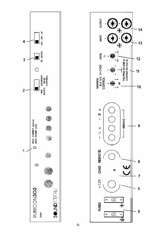
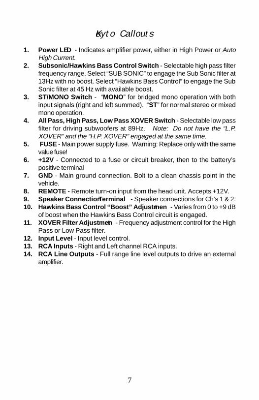
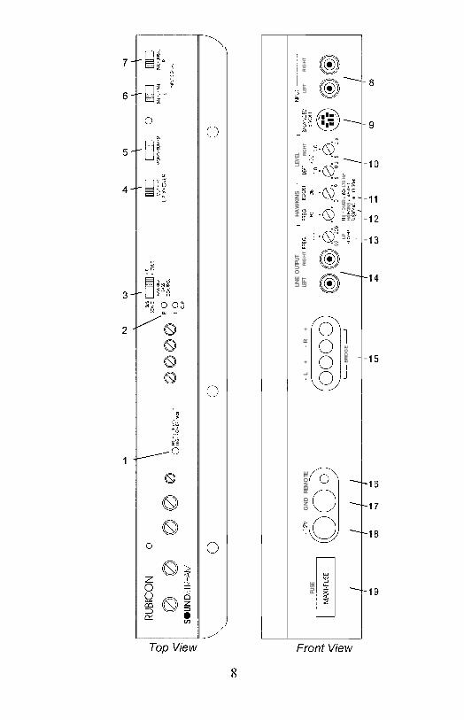
1. Power LED - Indicates amplifier power, either in High Power or AutoHigh Current.
2. Subsonic/Hawkins Bass Control Switch - Selectable high pass filterfrequency range. Select “SUB SONIC” to engage the Sub Sonic filter at13Hz with no boost. Select “Hawkins Bass Control” to engage the SubSonic filter at 45 Hz with available boost.
3. ST/MONO Switch - “MONO” for bridged mono operation with bothinput signals (right and left summed). “ST” for normal stereo or mixedmono operation.
4. All Pass, High Pass, Low Pass XOVER Switch - Selectable low passfilter for driving subwoofers at 89Hz. Note: Do not have the “L.P.XOVER” and the “H.P. XOVER” engaged at the same time.
5. FUSE - Main power supply fuse. Warning: Replace only with the samevalue fuse!
6. +12V - Connected to a fuse or circuit breaker, then to the battery’spositive terminal
7. GND - Main ground connection. Bolt to a clean chassis point in thevehicle.
8. REMOTE - Remote turn-on input from the head unit. Accepts +12V.9. Speaker Connection Terminal - Speaker connections for Ch’s 1 & 2.10. Hawkins Bass Control “Boost” Adjustment - Varies from 0 to +9 dB
of boost when the Hawkins Bass Control circuit is engaged.11. XOVER Filter Adjustment - Frequency adjustment control for the High
Pass or Low Pass filter.12. Input Level - Input level control.13. RCA Inputs - Right and Left channel RCA inputs.14. RCA Line Outputs - Full range line level outputs to drive an external
amplifier.
Key to Callouts
FUSE
jMA
X_FU
SE
+12V
GN
D
REM
OTE
LIN
E O
UTPU
Tr
HA
WKI
NS 1
LEV
ELlp
IN
PUl -l
-L
+
-R
+
LEFT
RIG
HT
FREQ
FREQ
IWO
STLE
FTRI
GH
TBA
lAlC
EDLE
FTR
IGH
T
- B
RID
GE -
I I
LPH
P XO
VER
l
60-
170
Hz
XO
MR
HAW
KIN
S n
30- l
OHz
, 1,
*SU
8Sot
1E l
13-3
oHz
I I
II
II
co
00

9
1. Power LED - Indicates amplifier power, either in High Power or Auto HighCurrent.
2. Clip Indicators - Indicates the signal output level is too high and the outputstage of the amplifier is clipping.
3. Subsonic, Hawkins Bass Control, H.P. XOVER Switch - Selectable highpass filter frequency range. Select “SUB SONIC” to engage the Sub Sonicfilter with no boost. Use the knob indicated by callout #12 to set the frequency:13-30Hz). Select “Hawkins Bass Control” to engage the Sub Sonic filter withavailable boost. Use the knob indicated by callout #12 to set the frequency:30 Hz to 70 Hz. Select “H.P. XOVER” to engage the amplifier’s high pass filterfor running satellite speakers. Use the knob indicated by callout #12 to setthe frequency: 70-160 Hz.)
4. Low Pass XOVER Switch - Selectable low pass filter for driving subwoofers.Use the knob indicated by callout #13 to set the low pass frequency. Note:Do not have the “L.P. XOVER” and the “H.P. XOVER” engaged at the sametime.
5. MONO/SUM/ST Switch - “MONO” for bridged mono operation with a singleinput signal (right channel only). “SUM” for bridged mono operation sum-ming two input signal (left and right). “ST” for normal stereo operation.
6. Left Channel Balanced/Unbalanced Input Selector - Select “BALANCED”to use the 6 pin Balanced signal input. Select “UNBALANCED” to use theRCA signal inputs.
7. Right Channel Balanced/Unbalanced Input Selector - Select “BALANCED”to use the 6 pin Balanced signal input. Select “UNBALANCED” to use theRCA signal inputs.
8. RCA Inputs - Right and Left channel RCA (Unbalanced) inputs.9. Balanced Signal Input Connector - 6-Pin Balanced input connector for use
with the Soundstream BLT/BLT4 Balanced Line Transmitter.10. Input Levels - Independent Left and Right input level controls.11. Hawkins Bass Control “Boost” Adjustment - Varies from 0 to +9 dB of
boost when the Hawkins Bass Control circuit is engaged.12. High Pass Filter Control Adjustment - Frequency adjustment control for the
High Pass filter, the Hawkins Bass Control filter, or the Sub Sonic filter.13. Low Pass Filter Control Adjustment - Frequency adjustment control for the
Low Pass filter.14. Line Outputs - Line level RCA outputs to drive an external amplifier (Note:
The outputs are full-range.)15. Speaker Connection Terminal - Speaker connections for Ch’s 1 & 2.16. REMOTE - Remote turn-on input from the head unit. Accepts +12V.17. GND - Main ground connection. Bolt to a clean chassis point in the vehicle.18. +12V - Connected to a fuse or circuit breaker, then to the battery’s positive
terminal.19. FUSE - Main power supply fuse. Warning: Replace only with the same value
fuse!
KEY TO CALLOUTS
10
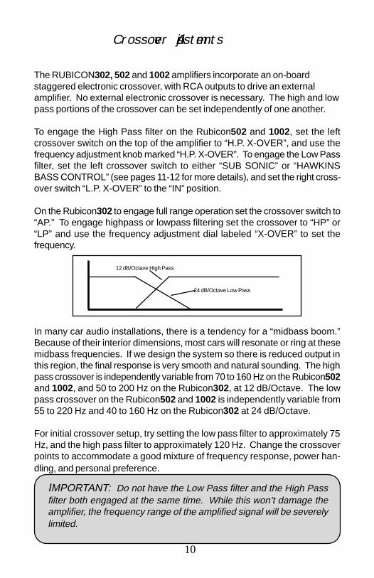
IMPORTANT: Do not have the Low Pass filter and the High Passfilter both engaged at the same time. While this won’t damage theamplifier, the frequency range of the amplified signal will be severelylimited.
In many car audio installations, there is a tendency for a “midbass boom.”Because of their interior dimensions, most cars will resonate or ring at thesemidbass frequencies. If we design the system so there is reduced output inthis region, the final response is very smooth and natural sounding. The highpass crossover is independently variable from 70 to 160 Hz on the Rubicon502and 1002, and 50 to 200 Hz on the Rubicon302, at 12 dB/Octave. The lowpass crossover on the Rubicon502 and 1002 is independently variable from55 to 220 Hz and 40 to 160 Hz on the Rubicon302 at 24 dB/Octave.
For initial crossover setup, try setting the low pass filter to approximately 75Hz, and the high pass filter to approximately 120 Hz. Change the crossoverpoints to accommodate a good mixture of frequency response, power han-dling, and personal preference.
The RUBICON302, 502 and 1002 amplifiers incorporate an on-boardstaggered electronic crossover, with RCA outputs to drive an externalamplifier. No external electronic crossover is necessary. The high and lowpass portions of the crossover can be set independently of one another.
To engage the High Pass filter on the Rubicon502 and 1002, set the leftcrossover switch on the top of the amplifier to “H.P. X-OVER”, and use thefrequency adjustment knob marked “H.P. X-OVER”. To engage the Low Passfilter, set the left crossover switch to either “SUB SONIC” or “HAWKINSBASS CONTROL” (see pages 11-12 for more details), and set the right cross-over switch “L.P. X-OVER” to the “IN” position.
On the Rubicon302 to engage full range operation set the crossover switch to“AP.” To engage highpass or lowpass filtering set the crossover to “HP” or“LP” and use the frequency adjustment dial labeled “X-OVER” to set thefrequency.
Crossover Adjustments
12 dB/Octave High Pass
24 dB/Octave Low Pass
Hawkins Bass Control - Theory and Use (302)
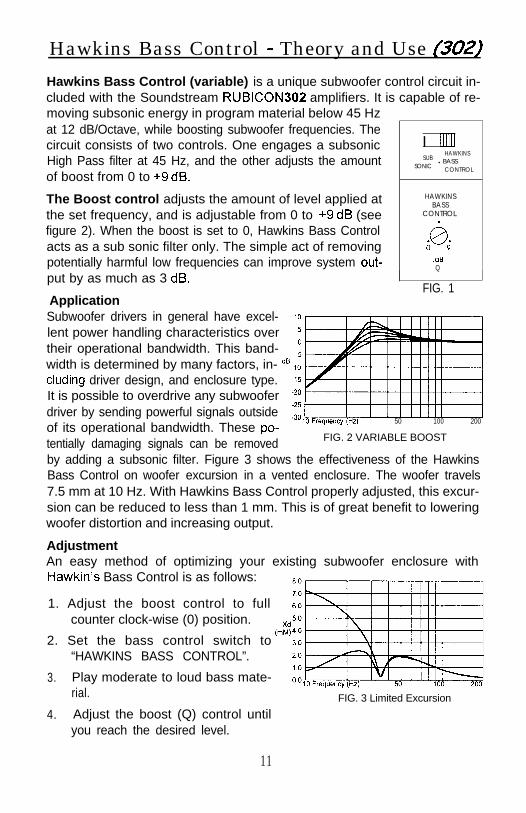
Hawkins Bass Control (variable) is a unique subwoofer control circuit in-cluded with the Soundstream RUBICON amplifiers. It is capable of re-moving subsonic energy in program material below 45 Hzat 12 dB/Octave, while boosting subwoofer frequencies. Thecircuit consists of two controls. One engages a subsonic I IllIllHigh Pass filter at 45 Hz, and the other adjusts the amount SUB
HAWKINS
SONICl BASS
of boost from 0 to +9 dB.CONTROL
The Boost control adjusts the amount of level applied atthe set frequency, and is adjustable from 0 to +9 dB (see
HAWKINSBASS
CONTROL.figure 2). When the boost is set to 0, Hawkins Bass Controlacts as a sub sonic filter only. The simple act of removing 0;I 9’potentially harmful low frequencies can improve system out- .dB
Q
put by as much as 3 dB.
Application
IFIG. 1
Subwoofer drivers in general have excel- 10lent power handling characteristics over 5their operational bandwidth. This band- _iwidth is determined by many factors, in- dB_10eluding driver design, and enclosure type. -15It is possible to overdrive any subwoofer -20driver by sending powerful signals outsideof its operational bandwidth. These po-
::z,, Frequency (Hz)50 100 200
tentially damaging signals can be removed FIG. 2 VARIABLE BOOST
by adding a subsonic filter. Figure 3 shows the effectiveness of the HawkinsBass Control on woofer excursion in a vented enclosure. The woofer travels7.5 mm at 10 Hz. With Hawkins Bass Control properly adjusted, this excur-sion can be reduced to less than 1 mm. This is of great benefit to loweringwoofer distortion and increasing output.
AdjustmentAn easy method of optimizing your existing subwoofer enclosure withHawkin’s Bass Control is as follows:
1. Adjust the boost control to fullcounter clock-wise (0) position.
2. Set the bass control switch to“HAWKINS BASS CONTROL”.
3. Play moderate to loud bass mate-rial. FIG. 3 Limited Excursion
4. Adjust the boost (Q) control untilyou reach the desired level.
11

MC - Tiieory and Use (502 & 1002)
‘“’ m %ERSONICHAWKINS
BASSCONTROL
r HAWKINS 1FREQ FREQ BOOST
110
@;. .g. ,c3,
.L.p. H.P: XOVER*70-160 HzXOVE R
1HAWKINS*30-70HzSUBSONIC 9 13-30Hz
FIG. 1 BASS CONTROL
Hawkins Bass Control (parametric) is a uniquesubwoofer control circuit included with theSoundstream RUBICON and 1002 amplifiers.It is capable of removing subsonic energy in pro-gram material while boosting subwoofer frequen-cies. The circuit consists of two controls. Oneadjusts the frequency of operation and the otheradjusts the range of boost. With both controlsadjusted fully counter-clockwise, no boost is ap-plied and the amplifier is flat in response down to20 Hz.
10
The frequency control (Hz) adjusts 5the starting point of the subsonic fil- oter. On the RUBICON and 1002, dB -5
-10the high pass filter has two frequency -15
ranges. When the bass control -20
switch is set to “SUB SONIC”, the -25
high pass filter frequency can be ad--30
justed from 13 Hz up to a maximumof 30 Hz. In this setting, no boost “Q” ,.control is available. This control is 5useful for setting the lowest frequency 0that your subwoofer will see (see fig- dB -5
ure 1). When the bass control switch-10
-15
FIG. 2 VARIABLE “Q”
is set to “HAWKINS BASS CON- -20
TROL”, the high pass filter frequency -25can be adjusted from 30 Hz to a maxi- - 3 0 ,
mum of 70 Hz. In this setting, there FIG. 3 VARIABLE HIGH PASS
is an available boost control of 0 to+9 dB.
-5dB
-10
-15
-20
-25
-30
FIG. 4 VARIABLE BOOST
The Boost control adjusts the amountof level applied at the set frequency.This is adjustable from flat (OdB) to +9dB. (See figure 2)
When the Boost is set to 0, Hawkinsacts as a sub-sonic filter only. (Seefigure 3) The simple act of removingpotentially harmful low frequenciescan improve system output by asmuch as 3 dB. (see figure 4)
12

ApplicationSubwoofer drivers in general haveexcellent power handling character-istics over their operational band-width. This bandwidth is determinedby many factors, including driver de-
8.0
7.0
6.0--
sign, and enclosure type. It is pos-sible to overdrive any subwooferdriver by sending powerful signals
FIG. 5 LIMITED EXCURSION
outside of its operational bandwidth. These potentially damaging signalscan be removed by adding a subsonic filter. Figure 5 shows the effective-ness of the Hawkins Bass Control on woofer excursion in a vented enclo-sure. The woofer travels 7.5 mm at 10 Hz. With Hawkins Bass Controlproperly adjusted, this excursion can be reduced to less than I mm. This isof great benefit to lowering woofer distortion and increasing output.
AdjustmentAn easy method of optimizing your existing subwoofer enclosure withHawkin’s “Hz” control is as follows.
1. Adjust frequency and boost control to full CCW position.
2. Set the bass control switch to “HAWKINS BASS CONTROL”.
3. While listening to music with strong bass content at a moderate level,slowly adjust frequency control clockwise. Listen for a reduction of bassresponse. Now, rotate frequency control slightly backwards. This servesthe purpose of removing the “subsonic” bass energy.
With Soundstream’s Hawkins BassControl, the boost and frequency con-trol can provide virtually any combina-tion of boost and cut to suit your de-signs. So, Hawkins Bass Control canprovide the “tailoring” needed for anytype of “assisted” design and anywoofer in any type of installation.
-5dB
-10
-15
-20
-25
-30
FIG. 6 VARIOUS SETTINGS
13

INSTALLATION STEP 1
SELECTING THE SPEAKER OUTPUT MODEThe RUBICON amplifier has the ability to operate in stereo, mixed mono, ormono mode. For stereo or mixed mono operation switch the amp to stereo.For bridged or mono applications switch the amplifier to mono. In mono modethe RCA inputs are automatically summed, so use both inputs.
The RUBICON and 1002 amplifiers have the ability to operate in any one ofthe following modes:
Stereo (STACT/Mixed Mono): Use this mode for either stereo operation (leftand right channels) or for Mixed Mono operation (stereo left and right channelsplus bridged mono for a subwoofer).
Summed Mono: Use this mode to get a bridged mono output while using boththe left and right inputs and gain controls.
Bridged Mono: Use this mode to get a bridged mono output while using onlythe right channel input and gain control (for use with a singular mono input).
Please follow the wiring schemes below for the correct operation:
BRIDGED MONO SUMMED MONO-L+ - R+ - L+ - R+
@ST
@
STMIXED MONO
STEREO -L* -R+I -- L+ -R+
+
_ + - +
14

INSTALLATION STEP 2
BALANCED / UNBALANCED INPUTThe RUBICON502 and 1002 amplifiers have the ability to accept either a stan-dard Unbalanced RCA signal input, or a Balanced “Pro Audio” style input signalswith the use of the Soundstream BLT Balanced Line Transmitter or some otherbalanced line audio source. Before installing your system, you should decideupon which signal type you wish to run. There are advantages to both:
ADVMAB
UNBALANCED INPUT BALANCED INPUT
1. Most preamplifier / source1. Improved Signal to Noise Ratio
units have Unbalanced RCA(S/N Ratio).
outputs (Industry Standard). 2. Excellent noise cancellation
2. No Interface module ischaracteristics.3. Immune to noise radiated in the
necessary. car audio environment.
The RUBICON amplifiers’ signal inputs accept a wide range of input level: from300 mVrms to 5.0 Vrms for both Balanced and Unbalanced inputs. For the bestS/N Ratio, we recommend that the input level controls be set as far down aspossible (rotated counter-clockwise), while maintaining an acceptable level ofoutput.
Using the “Unbalanced” RCA InputWhen using the Unbalanced RCA input, the R/GM channel input signal switchMUST be in the “UNBAL” position. Also, when first installing the amplifier usingthis input configuration, we suggest that the left channel input signal switch be inthe “UNBAL” position as well. If you experience alternator wine or other instal-lation noise with both switches in the “UNBAL” position, try moving the LEFTchannel input signal switch to the “BAL” position. This should remove anysystem noise due to the installation.
Using the “Balanced” RCA InputWhen using the Balanced 6-pin DIN audio input, both switches MUST be in the“BAL” position. Also, we recommend that when using this input configuration, theinput level controls be set to the “minimum” position (rotated counter-clockwise).The system gain should then be adjusted on the Balanced Line Transmitter,other balanced line audio source. For the pin configuration, see the diagrambelow:
“NOTE: The pin configura-tion shown in the diagramis the view looking into theBalanced input jack o n the
BALANCED-15 Volts*-,. zr + 15 Volts
- left Signal P b - Right Signal
+ left Signal/Ii Iv1
+ Right Signal
- Shield
15

( INSTALLATION STEP 3 7
WIRING
POWER AND GROUNDTo ensure maximum output from your RUBICON amplifier, use high quality, low-loss power and ground cables and connections. The RUBICON amplifiers willaccept up to 4 gauge power and ground cables. Determine from the chart belowthe minimum gauge power and ground wire for your application.
up to 10' up to 20’
I RUBICON302 I 4 or 8 guage I 4 gauge only I
I RUBICON502 I 4 or 8 guage I 4 gauge only ~~~ I1 RUBICON1002 1 4 gauge only 4 gauge only
CIRCUIT BREAKERS AND FUSESEXTERNALLike all audio components, the RUBICON amplifiers must be fused near thebattery. A fuse or circuit breaker must be located within 18” of the battery. This willprevent a fire in the event of a shorted cable. See the chart below to determine thecorrect fuse value.
INTERNALThe RUBICON amplifiers are fused with an automotive-type or Maxi-fuse. In theevent of a blown power supply fuse(s), replace with the correct value fuse found inthe chart below. Never replace the fuse with a higher value than what is sup-plied. This may result in amplifier damage and will void the warranty!
RUBICON Amplifier Fuse Values
Amplifier Fuse 1 Battery Fuse / Circuit Breaker 1
RUBICON302 I (2) 20 amp automotive I 50 amp IRUBICON502 I (2) 30 amp automotive I 80 amp
RUBICON1002 1 80 amp Maxi-fuse I 100 amp I
16
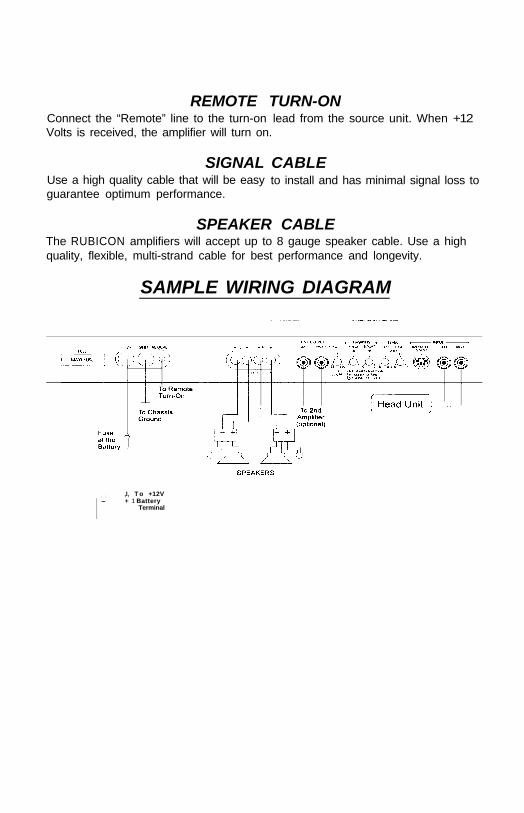
REMOTE TURN-ONConnect the “Remote” line to the turn-on lead from the source unit. When +12Volts is received, the amplifier will turn on.
SIGNAL CABLEUse a high quality cable that will be easyguarantee optimum performance.
to install and has minimal signal loss to
SPEAKER CABLEThe RUBICON amplifiers will accept up to 8 gauge speaker cable. Use a highquality, flexible, multi-strand cable for best performance and longevity.
SAMPLE WIRING DIAGRAM
I I-
,I, T o +12V+ 1 Battery
Terminal
17

4
INSTALLATION STEP 4
AMPLIFIER LOCATIONThe RUBICON amplifiers employ highly efficient circuitry, a custom-engineeredheat sink, and a unique Chassisink construction to maintain lower operatingtemperatures. Additional cooling may be required if the amplifier is located in atightly confined area or when driving especially low impedance loads at extremelyhigh levels.
When mounting the amplifier, it should be securely mounted to either a panel inthe vehicle or an amp board or rack that is securely mounted to the vehicle. Themounting location should be either in the passenger compartment or in the trunkof the vehicle, away from moisture, stray or moving objects, and major electricalcomponents. To provide adequate ventilation, mount the amplifier so that thereare at least two inches of freely circulating air above and to the sides of it.
MOUNTING THE AMPLIFIERa. Using the amplifier as a template, mark the holes on the mounting surface.b. Remove the amplifier and drill the holes for the mounting screws.c. Secure the amplifier to the mounting surface using the supplied hardware.
WIRINGa. Run and connect the audio signal and remote turn-on cables to the ampli-
fier from the source unit.b. Carefully run the positive cable from the amplifier to a fuse or circuit breaker
within 18” of the battery.c. Connect the fuse or circuit breaker lead to the battery. Leave the circuit
breaker off or the fuse out until everything is bolted down.d. Secure the ground cable to a solid chassis ground on the vehicle. It may be
necessary to sand paint down to raw metal for a good connection.e. Double check each and every connection!f. Re-connect the fuse or circuit breaker.
POWER UPPower up the system, there may be a 2-3 second delay from the time the sourceunit is turned on to the time that the amplifier turns on, which is normal. Once theamplifier LED is on and the source unit is playing, you should have sound comingfrom the speakers.
INSTALLA TION AND MOUNTING

5
INSTALLATION STEP 5
The input levels are adjusted by means of the input level controls located on thefront of the amplifier. This is a unique dual-stage circuit that adjusts both level andgain. This topology maintains better S/N Ratio even when using sources withminimal output.
In the ideal situation, all components in the audio system reach maximumundistorted output at the same time. If you send a distorted signal to an amplifier,it is simply going to amplify distorted information. The same holds true if anoutboard processor or crossover begins to distort before you have maximumoutput from the amplifier. By setting all components to reach clipping at the sametime, you can maximize the output of your system. For the RUBICON amplifiers,follow these steps for setting the input levels:
1. Turn the amplifiers’ input levels to minimum position (counter-clockwise)2. Set the source unit volume to approximately 3/4 of full volume.3. While playing dynamic source material, slowly increase the amplifiers’ input
level until a near maximum undistorted level is heard in the system.
The clipping indicators on the top of the amplifier let you know when the output ofthe amplifier is reaching its maximum level, and has begun to clip (502 and 1002only).
FRONT SPOILER
Once the amplifier is installed and the proper levels set, place the front spoiler inposition, and secure it on using the supplied hardware.
LEVEL SETTING
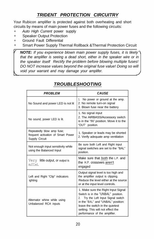
TRIDENT PROTECTION CIRCUITRY
Your Rubicon amplifier is protected against both overheating and shortcircuits by means of main power fuses and the following circuits:+ Auto High Current power supply+ Speaker Output Protection+ Ground Fault Differential+ Smart Power Supply Thermal Rollback &Thermal Protection Circuit
NOTE: If you experience blown main power supply fuses, it is likely’that the amplifier is seeing a dead short, either in the speaker wire or inthe speaker itself Rectify the problem before blowing multiple fuses!DO NOT increase values beyond the original fuse value! Doing so willvoid your warrant and may damage your amplifer.
TROUBLESHOOTING
PROBLEM CAUSE
1. No power or ground at the amp.No Sound and power LED is not lit 2. No remote turn-on signal
3. Blown fuse near the battery
1. No signal input
No sound, power LED is lit.2. The AIRBASS/Accessory switchis in the “IN” position. Move it to the“OUT’ position.
Repeatedly blow amp fuse;frequent activation of Smart Power
1. Speaker or leads may be shorted
Supply Circuit2. Verify adequate amp ventilation
Not enough input sensitivity whileBe sure both Left and Right input
using the Balanced Inputsignal switches are set to the "BAL"position.
Very little output, or output ismuffled.
Make sure that both the L.P. andthe H.P. crossovers aren'tengaged
Left and Right “Clip” indicatorsighting
Output signal level is too high andthe amplifier output is clipping.Reduce the level either at the sourceor at the input level controls.
Alternator whine while usingUnbalanced RCA inputs
1. Make sure the Right Input SignalSwitch is in the "UNBAL" position.2. Try the Left Input Signal switchin the "BAL" and "UNBAL" position:leave the switch in the quietestsetting. This will not effect theperformance of the amplifier.
20

Specificat/bns
4 ohm Stereo 2 ohm Stereo 1 ohm StereoMODEL (8 ohm Bridged) (4 ohm Bridged)(2 ohm Bridged)
TOTAL
(12.6 Vdc) (14.4 Vdc) (14.4 Vdc)POWER
30275W x 2 150W x 2 150W x 2
(150W x 1) ( 3 0 0 W x 1) ( 3 0 0 W x I) 300 Watts
502 100W x 2 250W x 2 250W x 2( 2 0 0 W x I) ( 5 0 0 W x 1) ( 5 0 0 W x I)
500 Watts
1002 2oow x 2 5oow x 2 5oow x 2( 4 0 0 W x I) (1000W x 1) (1000W x 1)
1000 Watts
THD <0. 1%Signal to Noise >100 dBFrequency Response 20 Hz to 20 kHz + 0.5 dBStereo Separation >90 dBDamping >200Input Sensitivity 300 mV to 5.0 VoltsInput Impedance 10k Ohms
Crossover SpecificationsRubicon302
Low Pass: 40 Hz - 160 Hz at 24dB/OctaveHigh Pass: 50 Hz - 200 Hz at 12dB/Octave
Rubicon502 and 1002Low Pass: 55 Hz - 220 Hz at 24 dB/OctaveHigh Pass: 70 Hz - 160 Hz at 12 dB/Octave
Hawkins Bass ControlRubicon302
Sub Sonic Filter: No boost, High Pass filter at 13 Hz.Hawkins Bass Control: 0 to +9dB Boost; Boost and Sub Sonic filterfrequency at 45 Hz.
Rubicon502 and 1002Sub Sonic Filter: No boost, High Pass filter from 13 to 30 Hz.Hawkins Bass Control: 0 to +9 dB Boost; Boost and Sub Sonic filtervariable from 30 to 70 Hz.
Dimensions (W x D x H)RUBICON302: 8.5” X 9.8” X 2.25”RUBICON502: 11 .0" X 9.8” X 2.25”RUBICON1 002: 16.0” X 9.8” X 2.25”
21