rtu-com / compact outstation with built-in modem …...dip switch rs232 sim card antenna brodersen...
TRANSCRIPT

40113/11_10 1
RTU-COM / Compact outstation with built-in modemUCR-XX/RCX
Brodersen Systems A/S * Islevdalvej 187 * DK-2610 Roedovre * Denmark * Tel (+45) 4535 2627 * Fax (+45) 4535 2629
Typical RTU-COM applicationINTRODUCTION
The RTU-COM unit is a compact outstation / RTU with built-in COMdevice as PSTN dial-up or GSM dual band modem. The unit has datalogging facilities and is designed for use in the industrial environment.
The unit is designed in a very compact 162 mm wide module for DIN-rail mounting (35 mm symmetrical ). Dimensions conform to DIN43880 (used for circuit breakers) thus insuring easy installation instandard installation panels and boxes widely available in theelectrical industry.
The RTU-COM can be delivered with a range of different powersupply versions including a battery/solar panel option.
Different power save options is available in the RTU-COM. Whenclosing down modem and analogue circuits and enter into sleepmode the power consumption can be reduced to a minimum. Allsleep mode facilities are controlled from the application program.
The RTU-COM has up to 16 integral I/O, covering digital inputs andoutputs, and analogue inputs as process signal or temperaturesensor inputs. 2 S0 counter inputs for flow meters etc. on all versions.
The unit can be programmed to perform simple control sequencesusing an IEC 1131-3 (PLC) programming language. The RTU-COMincludes facilities for local data logging, the process values to belogged are defined as part of the IEC 1131-3 application program.Programming, setup and data transfer is achieved by using theIOTOOL32.
In addition the RTU-COM can be programmed with the Straton forB-CON tool providing support for the IEC1131 programminglanguages Function Block and Ladder.
In the RTU-COM version with integrated GSM dual band modem theRTU offer a simple SMS message alarm and control functions.
The Modbus RTU protocol is used for data transfer over thecommunication link i.e. dial-up modem or GSM.
RTU-COM
VERSIONS/ORDERING CODES
UCR-10IO/RC1 10.D1TypeUCR UCR
Input/output4 digital input 4DI...P14 digital input/4 digital output 4DIO...P14 dig. in./4 dig.out./2 analog in. 10IO4DI/4DO/1AI/1 Pt100 in. 10IOA8dig. in/4dig.out/4 relay out. 8DIO..P1
OptionsRTU-COM (built-in modem) /RC
COMsGSM Dual band modem 1PSTN V32 dial-up modem 2RS232 interface 3
Power supply12V DC PS (not isolated) 00Mains PS 110-240V 10PS 24-48VDC/external PS 12V DC 30Battery/Solar panel PS 12V DC 40PS 24-60VDC/external PS 24V DC 50
Analogue input range (10IO type)0-10V/0-20mA D14-20mA D20-5V D30-20mA D6
Analogue input range (10IOA type)0-10V/Pt100 -50-100°C D114-20mA/Pt100 -50-100°C D210-20mA/Pt100 -50-100°C D61
PSTNModem
Modem
PC
CentralMonitoring
RTU8
RTU8
RTU-COM
Modem
RTU-COM
Rxd/TxdModemSystem
0 1 2 3 In
Power
C
0 1 2 3 Out C
C0 1 C
RS232 DIP switchSIM card
Antenna

Brodersen Systems A/S * Islevdalvej 187 * DK-2610 Roedovre * Denmark * Tel (+45) 4535 2627 * Fax (+45) 4535 2629
2
RTU-COM / Compact outstation with built-in modemUCR-XXIO/RCx
CONTENT
Introduction ....................................................................... 1Introduction text ...................................................... 1Module .................................................................... 1Typical application .................................................. 1
Version/Ordering code ..................................................... 1
Content .............................................................................. 2
Technical Description ...................................................... 3Input/Output ............................................................ 3Wiring Diagram ....................................................... 3CPU capacity/performance ................................... 3Local control ........................................................... 4Indicators ................................................................ 4I/O addressing (B-CONW) .................................... 4B-CONW addressing ............................................. 5Data logging ............................................................ 6Programme example (B-CONW) .......................... 6Log buffer ............................................................... 7Log buffer size ........................................................ 7Uploading data ........................................................ 7Real time clock/time base ...................................... 8Programmer port .................................................... 8Internal Serial interface to COM device ................ 8Handshake RTS Off .............................................. 8Handshake RTS On .............................................. 8Handshake RTS On/Off ........................................ 8Handshake RTS/CTS ............................................ 9RTS Leading ........................................................... 9RTS Trailing ............................................................ 9Modem control (Dial-up) ........................................ 9MODBUS protocol I/O database ........................... 9DLL or DDE interfaces ........................................... 9Station address ....................................................10Modbus address .................................................. 10Charger controller for battery and Solar panel ... 10Power save ........................................................... 10Normal mode ........................................................ 10Sleep mode ........................................................... 10Modem .................................................................. 11Analogue circuits .................................................. 11Digital inputs ......................................................... 11Power consumption ..............................................11Counter input ........................................................ 11
Special Register RTU-COM ........................................... 12Overview .............................................................. 12Error/Indicator/alert (inputs) ................................ 13Modem control registers ...................................... 13User registers ...................................................... 14Code switch (inputs) ............................................ 14Real time clock ..................................................... 14Time base ............................................................. 14Buffer level indicator ............................................. 14SMS Message ...................................................... 14Counter registers ................................................. 15
Technical data ................................................................. 16Interface ............................................................... 16
Internal Serial interface/Modem interface ..... 16Serial interface/programmer port .................. 16
Control and data logging ...................................... 16IEC 1131-3 (B-CON) ..................................... 16Real time clock ..............................................16Data logging ................................................... 16
Counters ........................................................ 17Power supply/charger .......................................... 17
Supply versions ............................................. 17Modems ................................................................17
GSM Dual band modem ................................ 17V.32 dial-up PSTN Modem ............................17
Digital input/output ................................................ 17Inputs ............................................................. 17Outputs ..........................................................17Isolation ..........................................................17Indicators ....................................................... 17
Relay Output ........................................................ 17Outputss ........................................................ 17Lifetime ........................................................... 17Contact material ............................................. 17Isolation ..........................................................17Indicators ....................................................... 17
Analog input (Dx) .................................................. 18Inputs ............................................................. 18Absolute maximum ratings ............................18Sampling interval ............................................ 18Measuring accuracy ...................................... 18Linearity ..........................................................18Temperature stability ..................................... 18Common mode input voltage ......................... 18Common mode rejection ratio ....................... 18Series mode rejection .................................... 18Isolation ..........................................................18
Pt-100 input ..........................................................18Sampling time ................................................. 18Input configuration ......................................... 18Input measuring ranges ................................. 18Resolution ...................................................... 18Measuring accuracy ...................................... 18Linearity ..........................................................18Temperature stability ..................................... 18
General ................................................................. 18Current consumption ..................................... 18Isolation ..........................................................18Ambient temperature ..................................... 18EMC ................................................................18Climatic ........................................................... 18Mechanical ..................................................... 18Protection ....................................................... 18Mounting ......................................................... 18Terminals ........................................................ 18Housing ..........................................................18Dimensions ....................................................18
Code switch/address selector ...................................... 18
Table analogue inputs ................................................... 19
Circuit configuration (digital) ......................................... 19
Circuit configuration (analogue) ................................... 19
Circuit configuration (Pt-100) ....................................... 19
Configuration .................................................................. 20
Notes/remarks ................................................................. 21
Appendix A ......................................................................22Typical log upload time ......................................... 22

40113/11_10 3
RTU-COM / Compact outstation with built-in modemUCR-XX/RCX
Brodersen Systems A/S * Islevdalvej 187 * DK-2610 Roedovre * Denmark * Tel (+45) 4535 2627 * Fax (+45) 4535 2629
TECHNICAL DESCRIPTION
Input/outputThe RTU-COM basic I/O fit can include up to 10 input/outputterminals. Serial I/O options are available:
Version UCR- 4DI 4DIO 10IO..Dx 10IOA..Dxx 8DIO
Digital inputs(10-30V DC) 4 4 4 4 8Digital outputs(PNP o. c.) 0 4 4 4 4Analogue inputs(0-10V/4-20mA) 0 0 2 1 0Pt100 inputs 0 0 0 1 0Relay outputs 0 0 0 0 4
All digital I/O´s are equipped with opto-couplers. The analogue inputshave galvanic isolation between the individual channels. Solid staterelays are used for multiplexing the analogue inputs. Pt100 input isnot isolated.
Wiring diagram
See the installation manual enclosed with the module, for more wiringdetails.
CPU capacity/performanceThe RTU-COM is equipped with an 8 bit micro-controller. The timerelated performance versus capacity of the RTU-COM is dependentupon the actual load on the micro controller, which directly relates tothe application and therefore the technical data herewith cannot beconsidered in isolation.
Wiring for type 40 battery and solar panel
+ -
>14
<11V
+
-
+ -
Solarpanel
+ -Battery
Internal fuse3.15A
InternalRTU-COMsupply
Internal fuse can be replacedby removing the left end cap.Fuse type: 3.15At 5x200mm Littelfuse 218.315.
Config portRS232
PSTN line output(only PSTN)
Analogue input
Pt-100 input
DIP switch foraddressing/setup
SIM card holder(only GSM)
FME antenna connectorfor GSM (only GSM)
UCR-10IO
Mains supply
DC supply
+ -
Supply for DI/DO
Rxd/TxdGSMSystem
Power
In C 0 1 2 3
RS232 DIP switchSIM card
Antenna
DC output Analogue input
-+
0 1 2 3 Out C
C0 1
Externalsupply10 - 30V DC
R L
-
+
+
-
I ?
Externalsupply10 - 30V DC
1 2 3 4 5 6 7 8 9 1 0
ON
C
+
-R L
t°
I ?
RS232 communication port(RS232 type only)
Wiring diagramUCR-8DIO
UCR-10IO
Rxd/TxdGSMSystem
Power
DI
DO
Rx/Tx PowerSystem
Config portRS232
DIP switch foraddressing/setup
SIM card holder(only GSM)
FME antenna connectorfor GSM (only GSM)
Mains supply
DC supply
+ -
Supply for DI/DODC output
0 1 2 3 Out C C 4 5 6 7 8 9 10 11
In C C 0 1 2 3 4 5 6 7
0 1 2 3 4 5 6 7
0 1 2 3 4 5 6 7
-+
+
-
Externalsupply10 - 30V DC
ON
RS232 communication port(RS232 type only)
Externalsupply10 - 30V DC
R L
-
+
+
-R L
���
����
���
����
���
���
���
���
RS232 DIP switchSIM card
Antenna

Brodersen Systems A/S * Islevdalvej 187 * DK-2610 Roedovre * Denmark * Tel (+45) 4535 2627 * Fax (+45) 4535 2629
4
RTU-COM / Compact outstation with built-in modemUCR-XXIO/RCx
IndicatorsThe RTU-COM is equipped with 4 status LEDs.
Indicator Status
Rxd/Txd Indicate serial communication to the built-in modem
On: OKSystem :Controller error
Off: General fault or no powerPower On: OK
Off: No power
Modem GSMOn: Searching for network
: Connected to provided network: Connected to network and on-line
Off: Modem off
PSTNOn: DCD (Data Carrier Detect) onOff: DCD (Data Carrier Detect) off
I/O addressing (B-CONW)The address of the I/O in the RTU-COM has the same structure asother Series 2000/4000 products. The I/O´s are separated into 4 datatypes;
Digital I/O (DI/DO)Reflect the physical digital input and output on the node. If you wantto have them in our IOTOOL32 database, they need to be defined inthe B-CONW application program.
Analogue (AI)Reflect the physical analogue input on the node. If you want to havethem in our IOTOOL32 database, they need to be defined in the B-CONW application program .
Auxiliary type 1 (YI/YO)The YI/YO is used for handling derived data from module database toPC database. As it is defined in figure xx. Eg. any output informationfrom the master PC has in B-CONW to be read in a YI register (wi6000-7999).
The RTU-COM handles bits (Boleans) and Integers (8/16 bit). Analoguevalues have to be handled as integers; floating point operation (Reals)is not supported.The PC software tools use words (16 bits) as a reference foraddressing the I/O, but as the RTU-COM is equipped with an 8 bitcontroller, the addressing uses bytes (8 bits) as a reference.The inputs and outputs are numbered in the order they appearphysically (left to right). Please note that input/output and analogue/digital are numbered separately.
DI AI DO AO
B-CONW Application Program
WI 0-1999 WI 2000-3999 WO 0-1999 WO 2000-3999
Physical I/O on RTU-COM node
DI AI ZI* DO AO ZO*YI YO
Master Database
IOTOOL32 /DDE / DLL
RTU-COM
Master/IOTOOL32
*ZI/ZO is gateway I/O - not used in standard RTU8.The ZI/ZOs are used for handling data throughspecific drivers for 3rd party equipment.
Communication Layer (MODBUS)
YO YI
WO 6000-7999 WI 6000-7999 Direct Passed I/ODI AI DO AO
Local controlThe RTU-COM compact outstation includes an IEC 1131-3 (B-CON)programming facility; it can be programmed using Instruction listprogramming language.Local processing and data handling are configured using a PC withthe programming tool installed. The B-CON (IEC 1131-3) programmingtools include an integrated editor, compiler, debugger, and down-loadfacility, for developing application programmes and to down-load themvia the programmer port to the RTU-COM or modem.
Examples of instructions used in the IEC 1131 language:LD load (read) value e.g.: input or internal registerST store (write) value e.g.: output or internal registerAND logical and e.g.: 2 inputsADD add 2 valuesMUL multiply 2 valuesR reset e.g.: an outputGT greater than, compare 2 values
The compiled instructions are down-loaded into Flash memory in theRTU-COM. The application programme can be up to 23k bytes. Asimple load (LD) or store (ST) instruction require only about 10 bytesof memory.The RTU has in total 2048 internal registers called BM registers. Thefirst 30-40 BM registers are reserved for use by the specific RTU-COM function like system reports, dial-up, realtime clock, log, SMSfunctions etc.. The rest is used in the B-CONW application programfor handling data. Registers from BM512 and up is battery backed -i.e. keep values stored if RTU is powered off.From the factory the RTU-COM is default loaded with a small B-CONW program defining the actual I/O, making them readable fromIOExplorer.
�� ������ ���� �
������������������������������
������� ����
������� �! �����"��������#�
�#��! ���"��"$�� �%"�&'!!� �%�(���$��
��)#���"�* �'!*� ���+��,*
RS232
40113/11_10 5
RTU-COM / Compact outstation with built-in modemUCR-XX/RCX
Brodersen Systems A/S * Islevdalvej 187 * DK-2610 Roedovre * Denmark * Tel (+45) 4535 2627 * Fax (+45) 4535 2629
B-CONW Addressing
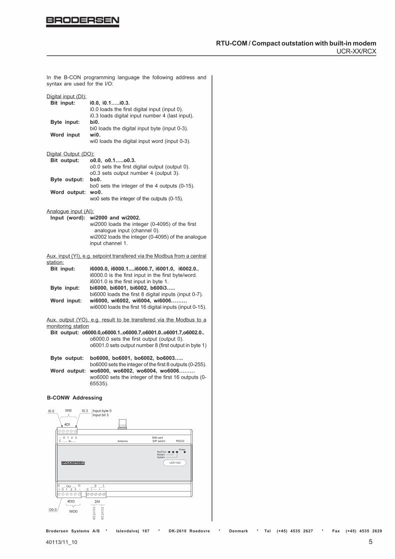
In the B-CON programming language the following address andsyntax are used for the I/O:
Digital input (DI):Bit input: i0.0, i0.1…..i0.3.
i0.0 loads the first digital input (input 0).i0.3 loads digital input number 4 (last input).
Byte input: bi0.bi0 loads the digital input byte (input 0-3).
Word input wi0.wi0 loads the digital input word (input 0-3).
Digital Output (DO):Bit output: o0.0, o0.1…..o0.3.
o0.0 sets the first digital output (output 0).o0.3 sets output number 4 (output 3).
Byte output: bo0.bo0 sets the integer of the 4 outputs (0-15).
Word output: wo0.wo0 sets the integer of the outputs (0-15).
Analogue input (AI):Input (word): wi2000 and wi2002.
wi2000 loads the integer (0-4095) of the firstanalogue input (channel 0).
wi2002 loads the integer (0-4095) of the analogueinput channel 1.
Aux. input (YI), e.g. setpoint transfered via the Modbus from a centralstation:
Bit input: i6000.0, i6000.1....i6000.7, i6001.0, i6002.0..i6000.0 is the first input in the first byte/word.i6001.0 is the first input in byte 1.
Byte input: bi6000, bi6001, bi6002, b600i3…..bi6000 loads the first 8 digital inputs (input 0-7).
Word input: wi6000, wi6002, wi6004, wi6006………wi6000 loads the first 16 digital inputs (input 0-15).
Aux. output (YO), e.g. result to be transfered via the Modbus to amonitoring station
Bit output: o6000.0,o6000.1..o6000.7,o6001.0..o6001.7,o6002.0..o6000.0 sets the first output (output 0).o6001.0 sets output number 8 (first output in byte 1)
Byte output: bo6000, bo6001, bo6002, bo6003…..bo6000 sets the integer of the first 8 outputs (0-255).
Word output: wo6000, wo6002, wo6004, wo6006………wo6000 sets the integer of the first 16 outputs (0-65535).
UCR-10IO
4DI
I0.0 I0.3 Input byte 0Input bit 3
4DO
O0.0
2AI
WI2000
WI2002
Rxd/TxdModemSystem
Power
In C 0 1 2 3
RS232 DIP switchSIM card
Antenna
WI0
WO0
0 1 2 3 Out C
C0 1 C

Brodersen Systems A/S * Islevdalvej 187 * DK-2610 Roedovre * Denmark * Tel (+45) 4535 2627 * Fax (+45) 4535 2629
6
RTU-COM / Compact outstation with built-in modemUCR-XXIO/RCx
RTU-COM control and datalogging
Data loggingThe up-loading of data from the RTU-COM can be:
� Cyclic upload controlled by a central PC ( for example 24 hours)� Event driven (such as an alarm).� Upload on request from the RTU-COM.
The RTU-COM can log events and process values for later analysis.The data logging process can be divided into 3 sections:
� Defining the events and the selection of values to be logged.� Storage of data, with time stamp, in the log buffer (max. 480k
bytes).� Upload of the data from the module via Programmer port/
RS232 or modem to a PC for analysis.
The actual process values to be logged are selected using the IEC1131-3 programming facilities in the RTU-COM. Data logging isperformed by a dedicated element of the programming language. Thelog element has the following input parameters:
� Trigger.� Log identifier.� Address of the value(s) to be logged (digital wi0..., analogue
wi2000..., internal wm20....).� Number of values to be logged (0-120 words).
The trigger is a Boolean (0/1) which can be linked to an event, e.g.activation of a digital input, or it can be linked to the time base in orderto automatically log the defined values cyclically with a given timeinternal.
For further information regarding the time base and real time clock seebelow.
When the trigger input is activated the values specified will betransferred to the log buffer, once every scan of the applicationprogram. The process values will be marked with the LOGID and atime stamp derived from the built-in real time clock. The resolution ofthe time stamp is 0.1 second.It is possible to define more than one log element in the RTU-COM. ThelogID is normally a constant (bc) used to identify the actual values afterhaving uploaded the log buffer for analysis. Up to 32 log elements canbe specified each having its own identifier and trigger.The data to be logged uses the general rules for addresses andvariables used in IEC-1131 Instruction List (B-CONW) programme;refer to separate manual for further information. It is possible to selectany I/O or internal register (word) and the number of inputs/registersto be logged (in consecutive increasing order).
Syntax: log [trigger], [logid], [address], [no. of words]
Programme example (B-CONW):
main:
/Event loglog i0.0, bc0, wi2000, bc1/Logs the first analogue input with log identification 0/every time the first digital input is activated.
/Cyclic loglog m17.4, bc1, wi2000, bc2
/ Logs the 2 analogue inputs with log identification 1/every 10 minutes.
ep
40113/11_10 7
RTU-COM / Compact outstation with built-in modemUCR-XX/RCX
Brodersen Systems A/S * Islevdalvej 187 * DK-2610 Roedovre * Denmark * Tel (+45) 4535 2627 * Fax (+45) 4535 2629
C:\
Net 1Net 2
199920002001
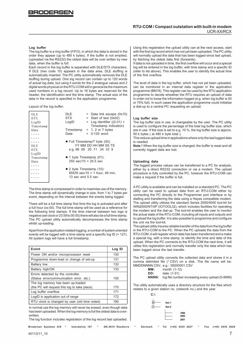
Log bufferThe log buffer is a ring buffer (FIFO), in which the data is stored in theorder they appear (up to 480 k bytes). If the buffer is not emptied,(uploaded via the RS232) the oldest data will be over written by newdata, when the buffer is full.Each record in the log buffer is separated with DLE/STX characters.If DLE (hex code 10) appears in the data area, DLE stuffing isautomatically inserted. The PC utility automatically removes the DLEstuffing during upload. One log record can contain up to 120 wordsof actual log data, but using 4 words for the 2 analogue values and 2digital words physical on the RTU-COM will in general be the maximumused numbers in a log record. Up to 16 bytes are reserved for theheader, the identification and the time stamp. The actual size of thedata in the record is specified in the application programme.
Layout of the log buffer:
������������� ���������� �� �� ��� �� �� ��� �� �� �������������� ���������� �� �� ��� �� �� ��� �� �� ��� �� �� �
The time stamp is compressed in order to maximise use of the memory.The time stamp will dynamically change in size, from 1 to 7 bytes perevent, depending on the interval between the events being logged.
There will be a full time stamp first time the log is activated and aftera full hour (xx:00). The full time stamp will be used as a reference forthe following time stamps. If the time interval between two logs isnegative (set clock or 23:59 to 00:00) there will also be a full time stamp.The PC upload utility automatically decompresses the time stampwhilst up-loading.
Apart from the application related logging, a number of system orientedevents will be logged with a time stamp and a specific log ID (> 127).All system logs will have a full timestamp.
DLE = Data link escape (0x10)STX = Start of text (0x02)LogID = Log identifier ((0-31) +
Timestamp indication)Timestamp = 1, 2 or 7 bytesData = 0-120 word
� Full Timestamp/7 byte (00): YY MM DD HH MM SS TSe.g. 96 09 20 11 24 33 9
� 1 byte Timestamp (01):255 sec/10 = 25.5 sec
� 2 byte Timestamp (10):65535 sec/10 = 1 hour, 49 min,13 sec and 5.5 sec
Event Log IDPower ON and/or microprocessor reset 130Programme down-load or change of set-up 131Battery low 132Battery high/OK 133Errors detected by the controller.(Status error/communication error, etc.) 150The log memory has been up-loaded(the PC will request this log to take place). 170Log buffer overflow 171LogID in application out of range 172RTU clock is changed by user (old time noted) 180
Using this registration the upload utility can at the next access, startwith the first log record which has not yet been uploaded. The PC utilitywill normally upload the data that has been logged since last upload,by fetching the oldest data first (forwards).If data is not uploaded in time, the first overflow will occur and a speciallog will be entered in the log buffer, with time stamp and a specific ID(refer to list above). This enables the user to identify the actual timeof the first overflow.
The level of data in the log buffer, which has not yet been uploaded,can be monitored in an internal data register in the applicationprogramme (BM18). This register can be used by the RTU applicationprogramme to decide wheather the RTU requires an upload of datain order not to loose the information logged (e.g. when log buffer is 50or 75% full). In such cases the application programme could initialisea dial-up to a central PC requesting an upload.
Log buffer sizeThe log buffer size in use, is changeable by the user. The PC utilityis used to configure the percentage of the total log buffer size, whichare in use. If the size is set to e.g. 10 %, the log buffer size is approx.50 k bytes ( at 480 k byte total ).This reduce upload time in applications where only the last logged datais needed.Note ! When the log buffer size is changed, the buffer is reset and allcurrently logged data are lost.
Uploading dataThe logged process values can be transferred to a PC for analysis,either by a direct RS232 connection or via a modem. The uploadprocedure is fully controlled by the PC, however the RTU-COM canmake a request if the buffer is full.
A PC utility is available and can be installed on a standard PC. The PCutility can be used to upload data from an RTU-COM either byconnecting the PC directly to the Programmer port interface or bydialling and transferring the data using a Hayes compatible modem.The upload utility utilises the standard Series 2000/4000 tool-kit forWIN2000/NT/XP (IOTOOL32), which includes facilities for operatingthe modem and the dial-up. The tool-kit enables the user to monitorthe actual state of the RTU-COM, including all inputs and outputs andto upload the log buffer. It is also possible to programme and configurethe unit via the tool-kit.The upload utility insures reliable transfer of the data from the log bufferin the RTU-COM to the PC. When the PC uploads the data from theRTU-COM ,it will register which data has been transferred and a makea special log, with a time stamp, to identify the time and date of theupload. When the PC connects to the RTU-COM the next time, it willutilise this registration and normally transfer only the data which hasbeen logged since the last transfer.
The PC upload utility converts the collected data and stores it in acomma delimited file (*.CSV) on a disk. The file name will be:MMDDNNNN.CSV, e.g.: 09200001.CSV
MM: month (1-12)DD: date (1-31)NNNN: log file number increasing every upload (0-9999)
The utility automatically uses a directory structure for the files whichrelates to a given station no. (network no.) and the year.
In normal use the log memory will never be erased, even though datahas been uploaded. When the log memory is full the oldest data is over-written.The log function includes registration of the log record last uploaded.

Brodersen Systems A/S * Islevdalvej 187 * DK-2610 Roedovre * Denmark * Tel (+45) 4535 2627 * Fax (+45) 4535 2629
8
RTU-COM / Compact outstation with built-in modemUCR-XXIO/RCx
Real time clock / time baseThe RTU-COM includes a real time clock and time base, which areused for both local control and data logging. The real time clockincludes battery backup (lithium battery).The real time clock is automatically entered into a log buffer every timethe trigger of a log element is activated. The real time clock is alsoavailable for use in the IEC 1131-3 application programme making realtime control possible, e.g. to start or stop or do any other time functionrelated to the control or the monitoring of the application.The real time clock can be adjusted via the programmer line directlyor via modem. The PC utility collecting the data from the RTU-COM,allows adjustment of the real time clock.When ever the clock is adjusted, an event with id 180 will be placedin the log. The log will be with a time stamp of the new time, and theold time value will be reported: YY.MM.DDHH.MM.SS100/S WD (WD= week day no.).
Programmer port / serial interface RJ11The RTU-COM programming interface includes a driver which is ableto handle both the Modbus protocol (RTU slave) and Brodersen RACcommands. The standard Modbus protocol is used for I/O transferand for configuration and up/down-load of programmes, a specialcommand set is used. The module has Modbus Slave address 1 asfixed address.
The RS232 port (6 pole modular jack RJ11) is equipped with hardwarehandshake signals. See section Internal serial interface how toconfigure the handshake signals.
RS232 programmer port (6 pole RJ11)
Pin no Signal Description/Remarks
1 SG Signal ground2 RTS Ready to send3 RX Receive data (in)4 TX Transmit data (out)5 CTS Clear to send6 GND Ground (Earth)
Internal serial interface to COM deviceThe RTU-COM internal serial interface includes a driver which is ableto handle also both the Modbus protocol (RTU slave) and BrodersenRAC commands. Hayes compatible modem control is implementedin the RTU-COM to serve the built-in line or GSM modem. When theRTU-COM is delivered with leased line modem or similar on-linecommunicating device, hardware handshake setup for RTS and CTSis instead enabled.
The use of RTS, CTS handshake, leading and trailing delays are userconfigurable via the PC utility menu. The settings are only active in nonmodem mode. In modem mode ( Dial-up ) the settings are don’t care.The handshake functions are as follows.
Handshake RTS OffRTS is kept inactive ( low ) at all time. RTS Leading and Trailing valuesare don’t care.
Handshake RTS OnRTS is kept active ( high ) at all time. RTS Leading and Trailing valuesare don’t care.
Handshake RTS On/OffRTS is inactive when receiving data, and become active whentransmitting data.The RTS Leading setting defines the delay from activating the RTSto the first character is transmitted.
The comma delimited file can be imported into a database or aspreadsheet for further analysis e.g. Microsoft Access, MicrosoftExcel and many other Windows programs.
Example of a comma separated file generated by the utility:
�������� ���� � ��������������� ����� � ����������� �� �� �� �������
����������� �� �� �� ����������������������� �� �� �� ��������������������� �� �� �� ���������������������������������� �� �� �� ����������������������� �� �� �� �������������������� �� �� �� ������������������������ �� �� �� ������������������� �� �� �� ����������������������������������� �� �� �� ����������������������������������� �� �� �� ��������������������� �� �� �� ���������������������� �� �� �� ������������������� �� �� �� ���������
�������� ���� � ���������� ��� � ����������� �� �� �� ��
The same example when imported into an EXCEL spreadsheet.Please note that the data separators and time format used, relate tothe national settings selected when installing Windows.
�������� ���� � ���������� ����� � ����������� �� �� �� ��
����������� �� �� �� � � �� �� ������������� �� �� �� � � � ��� ������������ �� �� �� � � � ���� ���� ���� ��������������� �� �� �� � � ��� ������������� �� �� �� � � � ������������ �� �� �� � � � �� �������������� �� �� �� � � ������������ �� �� �� � �� � ���� � ���� ���� ��������������� �� �� �� � �� ���� ���� ���� ��������������� �� �� �� � � �� ������������ �� �� �� � � � � � ������������ �� �� �� � � ������������ �� �� �� � �� �
�������� ���� � ��
�������� ��� � ����������� �� �� �� ��
The header and footer are inserted by the utility, the remaining partis data derived directly from the log buffer in the RTU-COM.The first column displays the time of the log. The second columndisplays the ID of the data being logged (the ID number defined in thelog element of the application program). The following columns displaythe actual process values (digital or analogue) which have beenlogged. The number of data-words are defined as a parameter for thelog element, in the application program.
If a data-word is used for individual bits (0-15), a conversion must bemade in the spreadsheet if it is required to view the individual bits.
For importing the log direct into another PC programme the IOTOOL32include a DLL interface to the upload facilities. Are used to import thelog data into e.g. SCADA, databases with the purpose of offeringextended historical data handling (trends, graphical views etc.).

40113/11_10 9
RTU-COM / Compact outstation with built-in modemUCR-XX/RCX
Brodersen Systems A/S * Islevdalvej 187 * DK-2610 Roedovre * Denmark * Tel (+45) 4535 2627 * Fax (+45) 4535 2629
Modem control (Dial-up)Both the RTU-COM and the central monitoring station can initiate adial-up to each other. The central monitoring station may dial the RTU-COM at time intervals, if the RTU-COM detects a situation, which ispre-defined to be a call situation, it can immediately dial-up the centralmonitoring station and report the actual condition.
The application related modem control (related to the process values)and conditions for making dial-up etc., are handled by the B-CONWapplication programme in the RTU-COM. Modem control is performedthrough 4 internal registers (BM2 to BM5).The calls are made to pre-stored numbers. By specifying alternative
numbers if a connection is not made to the primary number, then thesecondary numbers will be called in turn, until a successful connectionhas been made. The number of retries is limited to one cycle, i.e. afterthe pre-stored numbers and the number of retries per number havebeen called without success, the RTU-COM will suspend the dial-up.The maximum allowed number of dial-up attempts will be the numberof “pre-stored numbers to try” multiplied by “Retry count”. If the RTU-COM is unable to make a connection, an error indication is given tothe application, (m4.7 is set). The error flag is reset when the RTU-COM receives an incoming call (carrier detected) or when the valuein the dial register (bm2) is activated (changed from 0 to1) in order toforce a new dial-up.
Low level modem control is performed by the firmware which includesa modem initialisation routine, which is executed at power-up andevery time a dial-up is initiated.
The following Hayes commands are used to control the internalmodem:
+++ Enter command modeATZ Reset modemATE0 Echo offATD Dial upATH Hang upV0 Displays digital format
The string ATZ ATE0 V0 is used for modem initialisation by the RTU-COM. The second part of the initialisation string can be re-configuredto fit the actual application using the IOExplorer.
Default string: AT E0 V0 &C1 S0=1
&C1 Track presence of data carrier (DCD).S0=1 Auto answer.
Experience shows that modem initialisation can variate in specialapplications, but it is however highly recommended to keep the defaultsetting and investigate elsewhere in case of communication problemsbefore changing the default settings.
Modbus protocol / I/O databaseSerial communication according to Modbus (RTU mode) standard isused. The layout of the protocol and data base is very similar to theone being used in other Series 2000/4000 modules (first module = firstregister). The holding register addressing (Multiple read/preset com-mand type 03/16) is used for transfer. The RTU-COM also providesupport for Modbus Broadcast command. Mainly used for real timeclock synchronisation in RTU networks. The Modbus slave protocolis designed as tolerant to odd charcters added to a Modbus frame e.g.generated when passing through radio link or leased line multi dropconnections. See special data sheet specifing ModbusRTU in Brod-ersen RTU products.
The RTU-COM is supported by low level PC drivers for MS WIN2000/NT/XP plus a number of dedicated drivers for standard SCADApackages. The RTU-COM can be operated by the IOTOOL32telemetry driver, which includes all nessesary dial-up and modemfacilities.
DLL or DDE interfacesThe driver interfaces directly to most Windows programmes throughDLL or DDE interfaces.The data structure when using the Series 2000/4000 driver is commonfor all Series 2000/4000 products. The DLL includes a database whichis a mirror of the process values related to a given RTU-COM. Thevalues are separated into 4 data types, digital (DI/DO), analogue (AI/AO), and an auxiliary type (YI/YO).The user does not need to consider the actual Modbus registers usedfor the I/O in the RTU-COM. For each RTU, the number of I/O´s is
The RTS Trailing setting defines the delay from the last character istransmitted to RTS is deactivated.
Handshake RTS/CTSRTS is inactive when receiving data, and is activated when the RTUwants to transmit data. After activating the RTS, the RTU will wait forthe CTS to become active, before start transmitting. The RTS Leadingdelay is still valid in this mode, and an adjustable delay from CTS isactivated to first character is then possible. However by setting theLeading time to zero, there is no unnecessary delay from CTS to firstcharacter ( like normal RTS / CTS function ). After activating RTS theRTU wait up to 10 sec for the CTS signal. If timeout occur ,transmissionis discarded, and the RTU wait for a new request.
RTS LeadingThe RTS Leading define the delay time from activating RTS totransmitting the first character.The RTS Leading value is configurable in the range 0..500 of 10msunits. Ie. up to 5000 ms.
RTS TrailingThe RTS Trailing define the delay time from the last character istransmitted to RTS is deactivated. The RTS Trailing value is configurable in the range 0..50 of 10 msunits. Ie. up to 500 ms.
Note!When setting the Leading value to a long time ( e.g. 5 sec ) it could bedifficult to changes configuration and download Bcon programs duetimeouts in the driver. It is advisable not to use longer delay thannecessary, and configure RTS Leading delay as the last part whenusing long delays. If the RTU is inaccessible due long delays, themodule setting could be reset to default by setting all code switchesON.
Protocol on serial interfacesThe standard Modbus protocol is used for I/O transfer and forconfiguration and up/down-load of programmes a special commandset is used. The concept and the facilities are compatible with otherSeries 2000/4000 products, enabling the user to combine productswithin the product range.The Series 2000/4000 Modbus driver with DLL and DDE interface canbe used directly to link the RTU through the telephone network to acentral PC for monitoring, data upload and analysis.
Modbus holding registers (40000...) are used for the I/O transfer. Theactual I/O´s are automatically mapped into the holding registersaccording to the actual I/O configuration.For programme down-load, setup and log data, a transfer specialprotocol is used (still using the Modbus frame).
The RTU has a selectable address. For modem operation, a logicaladdress (station no., 0-65535) is used for identification of each RTU-COM. Using the Series 2000/4000 tool-kit each station will have itsown net, thus the station number and net number are the same.In non dial-up modem mode Modbus address 1-31 is used ( e.g. leasedline multi drop systems).

Brodersen Systems A/S * Islevdalvej 187 * DK-2610 Roedovre * Denmark * Tel (+45) 4535 2627 * Fax (+45) 4535 2629
10
RTU-COM / Compact outstation with built-in modemUCR-XXIO/RCx
specified by type and number. The Modbus driver automaticallyimports the data received, via the Modbus, into the correct positionin the data base.The driver can be configured to perform an automatic connection toeach RTU at a given time interval and the driver will also accept callsinitiated by an RTU.The I/O data, collected by the driver, is easily accessed by theapplication programme specifying a unique address consisting of:
<data type><Network/station><node/island><module/group<[>I/O terminal>]
For further information regarding addressing and facilities refer to theseparate description of the drivers and the Series 2000/4000 tool-kits.DLL facilities also available for log upload as earlier described.
Station address (dial-up mode)When using dial-up modems connected to the Public SwitchedTelephone Network, a number of Remote units will normally enter acentral monitoring station through the same physical connection. Inorder to be able to identify the Remote units, the station number istransferred in the first input holding register.
The station no. (0-65535) is the sum of the binary value selected usingcode switches 1-5 and the binary value of the logical addressconfigured in the RTU-COM using IOExplorer (default = 0).The central monitoring station must use the station address to directthe received data to the correct location.
Station address defined as:
The Modbus address (physical address) is set to address 1 (inde-pendent of the switch) when modem control is enabled.Please note that the PC Modbus driver only supports stationnumbers 0-1999.
Modbus address (non dial-up modem mode - Option)When the non dial-up mode is enabled in the RTU-COM, it uses theModbus address to identify itself. In this mode the 5 address DIPswitches defined the Modbus address, and the logical addess isignored.Note that the modem should be disabled in the config table if notpresent.
Charger controller for battery and solar panelIn Power supply version 40 the RTU-COM is equipped with a batterycharger controller for use with solar panel. 12V battery and solarpanel are connected direct to the RTU-COM. The controller ensurethat battery is not over charged. When the battery voltage levelreach 13,8-14,0V the solar panel is disconnected. When the voltagelevel falls to 12,6-12,8V the solar panel is re-connected to chargethe battery. To prevent the battery to be deep discharged, thecharger controller will cut the supply to the RTU-COM at 11V butalready at 11,5 V DC the status bit BM9.6 for battery low alarm willbe set to 1. And when the solar panel have charged the battery andthe voltage level reach 12V, the controller connect the power to theRTU-COM again.
Address plus Logical address(5 bit / 0-31) (11 bit / setup in
IOExplorer as ainteger value)
Station address
Typical tinkle charge and low discharge cycle
14V DC
12V DC
10V DC
connectdisconnect
connectdisconnect
13,8-14,0V
12,6-12,8V
RTU PS cut off11,0V
RTU PS on12V DC
11,5V battery low alarm
Solar
RTU PS
RTU-COM Power saveRTU-COM is designed for providing power saving features. The RTU-COM has implemented the following power saving options in thehardware:
• Modem power on and of.• Power the analogue inputs circuits on and off.• Heart beat for trigging the CPU in reduced power mode.• Configurable interrupts for waking up the CPU when activating
digital inputs.• Wake up facility when receiving calls via interrupt connected to
Ring Indicator.• Wake up facility when connecting to the programmer port and start
sending data.
The applications program B-CON control and define when and howthe options are used.
In the firmware some important measures are taken to control andmanage the household in relation to the basic low power option.
Below are listed these basic parameters:- Update of input, outputs, BM registers, and other process param
eters are finished, before entering sleep mode.- After wake up by an incoming call (RI interrupt activated) or
connecting to the Programmer port (RxD activated), the moduleis kept in normal mode until communication has ended or there isno more activity on the programmer port. An in-activity timerfunction on the Rxd/Txd programmer port with 15s is implemented.
- When power up modem the firmware holds dial command untilproper initialised.
- When power on the analogue circuit, a delay for the analogue valueto stabilise before release is implemented.
The total power consumption is dependable of application require-ment, and is totally controlled by B-CON application programme. E.g.the module could sleep and just wake up every hour for a few seconds,log an analogue value, and enter sleep again. Modem and/or analoguecircuits could be on or off during normal or sleep mode. Any combi-nation is possible. Turn off modem and analogue circuits and entersleep mode to obtain max power reduction.
The RTU-COM will basically have two modes;Normal modeThe CPU is running constantly, and B-CON application is executedat regular intervals like a normal RTU module. However modem and/or analogue circuits could be turned off to save power, if not used/needed.
Sleep modeSleep mode is a power saving mode where the CPU crystal (codeexecution) is stopped, for maximum power save . Each 250 ms aheartbeat interrupt wake the CPU shortly to service watchdog andother firmware housekeeping. The Dallas 80C320 CPU internal ringoscillator provides instantaneous code execution, when waked by
1 2 3 4 5 6 7 8 9 1 0
ON ON
OFF
20 21 22 23 24
Code switch

40113/11_10 11
RTU-COM / Compact outstation with built-in modemUCR-XX/RCX
Brodersen Systems A/S * Islevdalvej 187 * DK-2610 Roedovre * Denmark * Tel (+45) 4535 2627 * Fax (+45) 4535 2629
interrupts, which eliminate X-TAL stabilisation time during sleep modehousekeeping. To resume normal mode, different events are possiblee.g. sleep time is expired or changes of digital input. This is controlledby a combination of configuration fields and BM register settings.Switch to sleep mode is controlled by the B-CON application pro-gramme. By entering the maximum seconds to sleep in WM44 and setWM40 to 1, the module enters sleep mode. The firmware terminatesall processes in an appropriate way, before sleep mode is entered.Note! Sleep is cancelled by firmware if communication is currentlyactive, or has been within the last 15 seconds. The applicationprogramme must then try later to enter sleep mode. A sleep responsecode register (BM42) is provided, to test which event caused normalmode resume or firmware sleep mode cancellation.All timers, counters, data etc. are frozen during sleep. I.e. B-CONapplication timers, counters, data etc. continue with the value, justbefore sleep, when normal mode is resumed.
A wake up occur when the module leave sleep mode, and normal modeis resumed. This is initiated by a hardware interrupt from heartbeat,digital input, modem RI or programming port Rx, and wake up themodule as follows.
Timeout:The maximum sleep time defined in WM44 is expired.
Digital Input:A digital input changes has occurred. See configuration possibilitieslater.
Modem ring:A incoming call (Ring signal) is received by the modem, wake up themodule, and communication could be established. This is of courseonly possible if power is applied to the modem during sleep.
Programming port:Programming port Rx input signal activity wake up the module, andcommunication could be established. I.e. when a PC is connected, themodule wakes up.
ModemModem power is turned on/off by the B-CON application. The modemcould then be off most of the time, and just turned on when commu-nication is needed, to reduce power. Power Control register BM46 isused to select modem mode. The modem is default on at power on.Note! It will take a while from B-CON turns it on, to the modem isinitialised and ready (especially GSM), and a B-CON dial commandis then not executed before the modem is ready. If the modem ispowered off, a dial is just ignored by the firmware.
Analogue circuitsThe analogue circuit power is turned on/off by the B-CON application.The analogue circuit could then be off most of the time, and just turnedon when needed, to reduce power. Power Control register BM46 isused to select mode. The analogue circuit is default on at power on.Note! It will take some time from B-CON turns it on to the AD converterand reference etc. is stabile. Bit 14 of the analogue word (invalid bit)is set to ‘1’ when analogue circuits are off, and during the stabilisationtime. This is used by B-CON application to check if analogue valuesare valid or not. If an external transducer is powered simultaneously,additional time must be expected, due to transducer settling time andanalogue input low pass filter time constant. The B-CON applicationprogrammer must take care of this. However if power is very critical,the module could sleep during the stabilising period.
Digital inputThe 4 digital input is configurable in a number of ways, and could wakeup the module. If digital input wake up function is enabled, all DI’s willhave the wake up function. Note: If wake up function is enabled andthe module is sent to sleep, using the counters on DI0 and DI1 will wakeup the module at each count.
Wake up can either be on a positive transition change (OFF to ON)or a negative transition change (ON to OFF). They are configured inpairs. DI0 + DI1 and DI2 + DI3. The following options are selected inthe configuration menu:
DI0 and DI1OFF->ON:A digital input ‘0’ to ‘1’ transition, wake up the module, and normalmode is resumed. The B-CON application program test whichevent caused the wake up, and take action accordingly.
ON->OFF:A digital input ‘1’ to ‘0’ transition, wakes up the module, and normalmode is resumed. The B-CON application program test whichevent caused the wake up, and take action accordingly.
DI2..DI3OFF->ON:A digital input ‘0’ to ‘1’ transition, wake up the module, and normalmode is resumed. The B-CON application program test whichevent caused the wake up, and take action accordingly.
ON->OFF:A digital input ‘1’ to ‘0’ transition, wake up the module, and normalmode is resumed. The B-CON application program test whichevent caused the wake up, and take action accordingly.
It is important to note that the digital wake up function actually onlywake up the module. It means than a DI change e.g. an alarm ona DI, must be activated for more than 300ms, to make sure thatthe module wake up and the B-CON program are able to performa scan to read what DI has changed so the application defined typeof action can be performed.
Power consumptionPower consumption is directly related to the actual application, i.e. typeof internal modem, number of I/O´s active on the RTU-COM etc.Below are examples for the standard RTU-COM versions. All figuresare typical consumption at 12V.
RTU-COM version UCR-10IO UCR-4DI UCR-4DIO UCR-10IOA UCR-8DIO
(AI) (AI)
min. max. min. max. min. max. min. max. min. max.
Controller/electronics/ 25 70 25 70 25 70 25 70 25 130LEDs/IO (DI) * * * *
Analogue IO 0 10 0 10 0 10 0 15 0 0
GSM modem idle 5 8 5 8 5 8 5 8 5 8
GSM modem on-line 100 200 100 200 100 200 100 200 100 200
PSTN modem idle 50 60 50 60 50 60 50 60 50 60PSTN modem on-line 60 100 60 100 60 100 60 100 60 100
*) Power consumption in sleep mode.
Note: The figures are estimates and are subject to change. If RTU-COM is used in solar panel application special power calculation sheetwill be required to calculate current consumption and to define batteryand solar panel requirements.
Counter inputTwo 32 bit counters is provided on digital input 0 and 1. The countersvalues are battery backed, when power is off. Each counter isprovided with a reset function. The counter values and reset arelocated in a number of BM registers. If the counter value overflow, it

Brodersen Systems A/S * Islevdalvej 187 * DK-2610 Roedovre * Denmark * Tel (+45) 4535 2627 * Fax (+45) 4535 2629
12
RTU-COM / Compact outstation with built-in modemUCR-XXIO/RCx
SPECIAL REGISTERS RTU-COMOverview
������� � ���� ���� �� �
��� ������������ ��� � �� ������� ��������� �
� � ������� ��������� �� �� ������������ ���
���� ������ �������� ���������� ����� !���"��!#�� ���" ���
$!�����%�%"&!������%�%��������� �������������%�%
��$ ����#������� �����& �&��'�&�$ #����#�(�� ������ �
�&�&'&�) *�������� ���&�� +������� ��&�, �������������-�����. �
��) ��������������������� ���� /��������-������������/%0����� �
����#��1203�������, ���� �������� ����.��4 �4�� �����# �
�4� �����#� ��4�� �����#$ ��4�$ �����#& ��4�& �����#) ��4�) �����#� ��4�� �����#, ��4�, �����#4 �
��5 �5�� �����#5 ��5� �����# � ��5"� �������� ������� -�!26. �
BM10 Seconds 0-59 RBM11 Minutes 0-59 RBM12 Hours 0-23 RBM13 Week day 1-7 RBM14 Date 1-31 RBM15 Month 1-12 RBM16 Year 0-99 RBM17 m17.0 0.1 second interval Trigger R
m17.1 1 second interval Rm17.2 10 second interval Rm17.3 1 minute interval Rm17.4 10 minute interval Rm17.5 1 hour interval Rm17.6 10 hour interval Rm17.7 not used
BM18 Log buffer 0-255 0: Empty 254: Full RBM19 SMS text messages R/WBM20 m20.4 SMS transmission OK R
m20.7 SMS transmission Rtime out (error)
BM21 m21.0-m21.1 counter reset Wm21.2-m21.7 not used
BM22 Counter 0 RBM23BM24BM25
wrap around and start from zero again.By default the counters are disabled, and must be enabled in the PCutility configuration menu before use. When counters are disabled theallocated BM registers are free for other use.The counters are firmware polled, which limit the count frequencywhen the CPU is loaded heavily. If the module is loaded with max. I/O, large B-CON program etc. only up to 60 Hz count frequency couldbe expected.Note ! When downloading B-CON application program, or changesof the module configuration, the counters are blocked for a shortperiod, and counts could be lost.

40113/11_10 13
RTU-COM / Compact outstation with built-in modemUCR-XX/RCX
Brodersen Systems A/S * Islevdalvej 187 * DK-2610 Roedovre * Denmark * Tel (+45) 4535 2627 * Fax (+45) 4535 2629
Error/indicator/alert (inputs)Run time errors and corresponding indicators are monitored/control-led using BM0 and BM1
Register DescriptionBM0 Runtime error/overflowBM1 m1.0 System indicator
m1.1 System indicator
Modem control registersThe modem is controlled from 4 internal registers (M-registers).
Register Description
BM2 Command register (output)0=No action, st. by1=Dial no. selected by bm32=Hang up3=Send SMS message4=Send SMS to no. of last received SMS
BM3 Telephone (selection) no. (0-29)
BM4m4.0 CTS, Clear to send (input)m4.1 DSR, Data set ready (input)m4.2 RI, ringing indicator (input)m4.3 DCD, Data carrier detect (input)m4.4-m4.5 Communication state (read only)
54 State Remark00 Idle No communication
(comcounter =0)01 Active Communication
(comcounter > 1)10 All updated Set when all inputs
has been read once
m4.6 Correct password receivedm4.7 Dial request suspended (1"=Error)
BM5 Communication counter
The command register (output) is used to initiate and terminate a call.The call is made to the pre-stored number selected in the telephoneregister, see above.
The telephone number (output) is selected from up to 30 pre-storedtelephone numbers to decide which number to dial. The pre-storedtelephone numbers are defined in the configuration menu, using theIO Explorer software. The telephone number register (bm3) can beused either to force the use of a given pre-defined number, by writingthe number into the register - or it can be used to read the actual numbercurrently being dialled. The automatic dial procedure writes the actualnumber into the register, allowing the B-CONW application pro-gramme to monitor the number being dialled and control it accordingly.
CTS, DSR, RI and DCD (input) are the handshake signals (bit inputs)from the modem, which may be used in the application programme tocontrol the modem.
The communication state (input) can be used to monitor when atransfer of I/O data has successfully taken place. The communicationstate is controlled by Modbus Holding register 49999. The PC driver(Modbus master) writes to the register when the PC has receivedall the registers defined.
������� � ���� ���� �� �
BM26 Counter 1 RBM27BM28BM29BM30 SMS write register R/WBM31BM40 m40.0 ‘0’ = Normal mode (default). R/W
‘1’ = Go to sleep mode.m40.1 ‘0’ = Enable DI change wakeup R/W
(default).‘1’ = Disable digital input changeswakeup.
m40.2 ‘0’ = Enable modem activity R/Wwakeup (default).‘1’ = Disable modem activitywakeup.
m40.3 ‘0’ = Enable programming port R/Wactivity wakeup (default).‘1’ = Disable programming portactivity wakeup.
m40.7 Not used.
BM41 Not used NA
BM42 Exit sleep mode response R0 = No event (sleep mode was not entered).1 = Timeout event wakeup.2 = Digital input change wakeup.3 = Modem activity wakeup.4 = Programming port activity wakeup.
BM43 Not used NA
BM44 Sleep time register R/W0...65535 sec to stay in sleep mode.0 is ignored.65535 no sleep timeout.
BM46 m46.0 ‘0’ = Enable analogue circuit. R/W‘1’ = Power off analogue circuit.
m46.1 ‘0’ = Enable internal modem R/Wcircuit.‘1’ = Power off internalmodem circuit.
m46.2-m46.7 not used NAWMxx Writeable register from SMS - R/W
see SMS message section

Brodersen Systems A/S * Islevdalvej 187 * DK-2610 Roedovre * Denmark * Tel (+45) 4535 2627 * Fax (+45) 4535 2629
14
RTU-COM / Compact outstation with built-in modemUCR-XXIO/RCx
Time BaseThe time base will typically be utilised to trigger the log elements inorder to facilitate cyclic logging and they may also be used to triggerother functions related to the actual application.
Register Time intervalM17.0 0.1 secondM17.1 1 secondM17.2 10 secondM17.3 1 minuteM17.4 10 minuteM17.5 1 hourM17.6 10 hourM17.7 not used
The output of the time base is active only for one scan in the applicationprogramme (e.g. 100 ms).All outputs of the time base are active for one scan immediately afterthe module is turned on (or reset). There after the time based, issynchronised to the real time clock meaning that the 10-minute-output(BM 17.4) is activated exactly at 11:00:00, 11:10:00, 11:20:00,11:30….
Buffer Level IndicatorBM 18 is used to indicate which part of the log buffer has not yet beenuploaded. The value is an integer (0-255).
Register Log bufferBM18 Value Level %
0 064 25
128 50192 75255 100
SMS Message / sendingThe RTU with GSM modem offers the possibility to send SMS alarmmessages, with or without variables.
The pre-stored SMS text messages are defined in the configura-tion menu, using IOExplorer. Up to 40 characters can be stored ineach of the 40 messages. Note: only 7-bit ASCII chars can beused, i.e. no special national characters are supported.
The variables in the SMS messages are defined by the syntax:
%[type]<regID>, where% defines start of variable[type] defines type of data. Default are used W forword. Value in is signed integer, range –32768 to +32767decimal<regID> defines B-CON data register id – e.g. WM512.Valid range; WM100-WM2046. Note: An integer (word)represent two byte memory registers and the number aredefining byte registers, so only even registers should beaddressed.
The message format is:Text text %Wnnn more text %Wnnn text (max. 40 chars)
Buffer empty
Buffer full / overflow
The communication counter (input) can be used to monitor if thetransfer of data is successful. In every read or write cycle on theModbus, the counter is incremented. The RTU-COM requires at leasttwo messages (Read and Write) to update. For third party equipment/software several messages might be required to update a remote unitdepending on the actual Modbus commands being used. In suchcases, data for the actual protocol driver must be consulted or thevalue must be set to a suitably high figure.
When the line connection is terminated, the communication state andthe communication counter are returned to 0-19.
User RegistersBM6 and BM7 (WM6) are directly derived from the “User” field in theconfiguration menu. By using IOExplorer it is possible to enterparameters into an application programme, e.g. a set-point withouthaving to re-compile.
Register DescriptionBM6 User register high byteBM7 User register low byte
Code Switch (inputs)The setting of the code switches are copied to internal registers (BM8/BM9) for monitoring purposes. Please note that the code switches areused by the firmware, therefore they cannot be used independently.
Register DescriptionBM8
m8.0 Code switch 1 Addressm8.1 Code switch 2 Addressm8.2 Code switch 3 Addressm8.3 Code switch 4 Addressm8.4 Code switch 5 Addressm8.5 Code switch 6 Not usedm8.6 Code switch 7 Not usedm8.7 Code switch 8 Not used
BM9m9.0 Code switch 9 Not usedm9.1 Code switch 10 Modem/RTU-COM config
Power Montor (type 40 solar charger controller)It is possible to monitor the condition of the external lead acid batteryand the mains supply in the application programme.Register ContentM9.6 Battery status (1=error, 0=OK)
Real Time ClockThe real time clock can be used in the application programme to start/stop or do any other time function related to the control or to themonitoring of the application.The real time clock and the time base is available in a number of internalregisters (BM10 to BM 17).
Register Content Range RemarksBM10 Seconds 0-59BM11 Minutes 0-59BM12 Hours 0-23BM13 Week day 1-7 1=Monday, 7= SundayBM14 Date 1-31BM15 Month 1-12BM16 Year 0-99

40113/11_10 15
RTU-COM / Compact outstation with built-in modemUCR-XX/RCX
Brodersen Systems A/S * Islevdalvej 187 * DK-2610 Roedovre * Denmark * Tel (+45) 4535 2627 * Fax (+45) 4535 2629
Cmd<value>, Where <value> is a decimal number within the range–32768 to +32767
E.g. "Cmd55".
The value 55 is stored in data register WM30.In the B-CON application program it is possible to use the registervalue to activate outputs or change setpoints etc.
The RTU will NOT respond to the caller.
Enter telephone number in the Telphone no list via SMS.Up to five telephone numbers in the telephone list in the configurationtable can be entered with a SMS message. This is done by using theSMS format;Cmdpno "phone no 0" "phone no 1" "phone no 2 " "... etc. - up to 5numbers.
Example: Cmdpno �+45123456� - will write +45123456 into telephoneno 0 in the list.
Existing number in the actual entry will be overwritten. If you do notenter any number but just define " " the entry will be overwritten withblanks.
If you put "Ack" (like AckCmd55) in front of your message, one ofthree possible acknowledge messages will be send to the caller:
If the caller is in the admission list and the message format is valid:RTUyy response, command accepted
If the received message format is invalid:RTUyy response, command rejected/error
If the caller is not in the admission list, the RTU will respond with:RTUyy response, no admittance
- where yy equals the RTU address.
SMS Safety / acknowledgement issuesIt is possible to enable a safety function, so only 5 predefined mobilephone numbers can change settings. If none is listed, SMS commandfrom any mobile phone is accepted. Is defined in the configurationmenu using IOExplorer.
When receiving SMS messages system acknowledgement must bereturned. See previous paragraph.
Counter registersBM 21..29 are used by the counters, if enabled. When the Reset bitis activated, the corresponding counter is cleared, and remaincleared as long as the Reset bit is activated.
Register Description
BM21 m21.0 Reset counter 0 m21.1 Reset counter 1 m21.2..m21.7 Not used
BM22 Counter 0 bit 0..7BM23 Counter 0 bit 8..15BM24 Counter 0 bit 16..23BM25 Counter 0 bit 24..31BM26 Counter 1 bit 0..7BM27 Counter 1 bit 8..15BM28 Counter 1 bit 16..23BM29 Counter 1 bit 24..31
SMS Service Center telephone no. can be entered in the configurationmenu. Often the number is not required as the GSM provider take careof this automatically.
The SMS option is controlled from the following registers.
Register DescriptionBM2 Command register (output)
3=Send SMS message4=Send SMS to last received SMS no.
BM19 SMS text message selection (0-39)
BM20 m20.4 SMS transmission status (1=OK)m20.7 SMS transmission time out (1=error)
Command register (output) is used to initialise the send SMS messageprocedure. This is done to the pre-stored number of SMS receiverselected in the telephone no. register BM3.If BM2 is set to 4, a selected message is send to the phone no of thelast received phone no.
Message selection (output). The text message is selected from thepre-stored message with BM19 (0-39).The SMS sending procedure state (read only) can be used to monitorwhen a SMS transmission has been successful or have failed. If thetransmission is successful the BM20.4 is set to "1" and cleared wheninitiating a new SMS transmission.If the transmission fails for some reason (e.g. SMS service no. is busyor wrong), the module retry after 60s. After 3 retries and fails BM20.7is set to "1" and the session is terminated.In case of an incoming call the session is set on stand-by, and resumedafter the incoming call is terminated.
Example
SMS text string 5 contains text:
“Tank %W512 level: %W514 cm”
The RTU will substitute %W512 with the value of WM register 512and %W514 with WM514 in the SMS string.Telephone list no 1 contains: +45 2242 3763
To send this text, the B-CON application program must do thefollowing:
Set BM19 = 5 (select SMS text string)Set BM3 = 1 (select a phone number from the list
(0…29))Set BM2 = 3 (send SMS message command)
If WM512 = 02H, WM514 = 036BH the following text will be send bythe RTU COM and read out on the receivers (phone no +45 22423763) display :
“Tank 2 level: 875 cm”
Parameters are formatted with leading zero suppression and ‘-‘(minus sign) as required. A parameter occupies from 1 to 6characters in the message.
SMS Message / receivingThe RTU with GSM modem is able to receive a message. To enableremote control of the application, the RTU will accept a message witha fixed text and format containing one parameter value. The parameteris stored in a fixed memory location in the B-CON data register area.
The SMS message format is defined by the syntax:

Brodersen Systems A/S * Islevdalvej 187 * DK-2610 Roedovre * Denmark * Tel (+45) 4535 2627 * Fax (+45) 4535 2629
16
RTU-COM / Compact outstation with built-in modemUCR-XXIO/RCx
TECHNICAL DATA
INTERFACE
Internal serial interface / modem interface:Signal level: RS232C/TTL.
Hardware handshake: DCD, DTR, DSR, RTS, CTS, RI
Baud Rate: 300, 600, 1200, 2400, 4800, 9600,19200
Format (default): 8 bit (binary), 1 start bit.No parity, 1 stop bit.
Protocol: Modbus slave (RTU mode).Error Check: CRC (16).
Modem control: Hayes compatible.
Dial-up (modem): DTMF or pulse dialling to pre-storedtelephone numbers.Up to 30 pre-stored numbers.Each number can be up to 20 digits.
Serial interface / programmer port:Signal level: RS232C/v.24.
Hardware handshake: RTS, CTS
Baud Rate: 300 - 9600
Format (default): 8 bit (binary), 1 start bit.No parity, 1 stop bit.
Protocol: Modbus slave (RTU mode).Error Check: CRC (16).
CONTROL AND DATA LOGGING
IEC 1131-3 (B-CON)Program memory (Flash): 23 Kbytes.Memory usage perinstruction line: 6-24 bytes.Typical maximumprogram size: 1500 instruction lines.Scan interval: 50-250 ms (note 1).
Internal registers (BM): 2048 (note 7).
Real time clockAutomatic correction for leap years.Accuracy: 25°C: Better than +/- 1 second per day.
-20 + 50°C: Better than +/- 5 seconds per day.Adjustment accuracy: ±1s.
Back-up battery: Internal Lithium battery (800 mAh).
Back-up time: min. 2 years (without external batteryor mains supply).
Data loggingCyclic log interval: 0.1, 1, 10 seconds. 1, 10 minutes. 1,
10 hours.Log memory: up to 480 kBytes.Time stamp: Time, date, year (compressed format).Resolution: 0.1 second.Number of log elements: max. 32.Log record: ID, time stamp, process values
(max. 120 words), see note 1.
B-CON Power save command and monitor registersA number of BM registers are used by the B-CON application program,in conjunction with some configuration registers, to control the sleepmode features in the RTU-COM
WM40 Sleep mode command registerInstructs firmware to close processes and enter sleep mode. One ormore of the wakeup possibilities could be disabled during sleep toprevent unwanted wakeup. Writing 1 will enter sleep and keepeverything enabled.
m40.0 "0" = Normal mode (default)."1" = Go to sleep mode.
m40.1 "0" = Enable DI change wakeup (default)."1" = Disable digital input changes wakeup.
m40.2 "0" = Enable modem activity wakeup (default)."1" = Disable modem activity wakeup.
m40.3 "0" = Enable programming port activity wakeup (default)."1" = Disable programming port activity wakeup.
m40.4..m41.7 Not used.
BM42 Exit sleep mode response registerA response code indicates which event caused the exit from sleepmode;
0 = No event (sleep mode was not entered).1 = Timeout event wakeup.2 = Digital input change wakeup.3 = Modem activity wakeup.4 = Programming port activity wakeup.
BM43Not Used
WM44 Sleep Time RegisterWord value range 0..65535. Units of seconds the RTU stay in sleepmode, unless another event occur which resume normal modeoperation before timeout (e.g. digital input change). Value 0 is justignored. Value 65535 (0xFFFF) the timer is disabled and the RTU willbe kept in sleep mode until another event occur.
BM46 Power Control RegisterEnable, disable power to optional circuits. The circuits are enabled bydefault at POR and B-CON start
m46.0 "0" = Enable analogue circuit."1" = Power off analogue circuit.
m46.1 "0" = Enable internal modem circuit."1" = Power off internal modem circuit.

40113/11_10 17
RTU-COM / Compact outstation with built-in modemUCR-XX/RCX
Brodersen Systems A/S * Islevdalvej 187 * DK-2610 Roedovre * Denmark * Tel (+45) 4535 2627 * Fax (+45) 4535 2629
Back-up battery: Internal Lithium battery (800 mAh).Back-up time: min. 2 years (without external battery
or mains supply).Log upload time: typically 5 seconds per 1k byte
@9600 Baud.See appendix for table with typical logupload time.
Counters:Minimum pulse /pause width: 6msMax. counting frequency: 80Hz
POWER SUPPLY/CHARGER Supply Versions:
00 10 30 40 50Supply voltage 12V 110-240V 24-48VDC 12VDC24-60Vnominal DC AC/DC batt. DCSupply voltageabsolute maximuminput range 10-14,8 100-265 20-60V 12-15V 20-72VMains frequency DC only 40-60 Hz DC only DC only DC onlyMax Power 6W 18W 14W 24W 14W Outputs:Output current, total 1,1 A 0,9 A 2A
0,9A
Output 12VDC 12V 12V - 24Vexternal output (= suppl.) +/- 1,5V +/- 0,5V +/-1VMax. current 400mA 400mA 400mA 300mAIsolation:
Input/mains (primary)to electronics 0V 3,75kV 0V 3,75kV
Type 40 figures are subject to change.Note 8, 9, 10.
MODEMS
GSM Dual band modemStandards: GSM 1800/1900 Class1(1W),GSM
phase2.AT command set: Based on V.25ter and GSM 07.05
& 07.07.No auto-framing available.
SMS: Mobile Originated (MO) and MobileTerminated (MT).Mode Text & PDU point to point.
Cell broadcast: In accordance with GSM 07.05Data mode: Asynchronous 2400, 4800, 9600
bits/s.Transparent / Non-Transparentmode.Mode 3.1 KHz (PSTN) and V110(ISDN)
Antenna: External antenna via SMA conn.SIM Card: Voltages: 3 and 5V supported.Approvals: CTR19 and CTR20
PSTN ModemConnector: 6 pole RJ11 type modular jackModem Speeds: V.32bis, V.32, V22bis, V.22A/B,
V.23and V.21, Bell 212A and 103Error correction: V.42 LAPM and MNP 2-4
Data compression: V.42 bis and MNP5 ( MNP10 datathroughput enhancement)
AT command set: Hayes compatible.Linearity: Better than ± 1LSB.Temperature stability: Better than ± 50ppm/°C (typical).
Common mode input voltage: Max. ±80V DC (note 1).Common mode rejectionratio: Min. 60dB (typical 72dB).Series mode rejection: Min. 30dB (50-120Hz)
Isolation (input to input): 500V (note 1).
Approvals: Pan European CTR21 standard.Isolation line interface: 1500 V.
DIGITAL INPUT/OUTPUT
Inputs:Input voltage activated: 10-30V DC (note 2,3).Input voltage deactivated: Max. 3V DC.Input current: 12V DC: Typical 3mA.
24V DC: Typical 6mA.Input delay: Typical 1ms.
Outputs:
External voltage: 10 - 30V DC (note 2,3).Output voltage drop: Max. 1.5V (output activated).Output current: Max. 0.5A.Output peak current: Max. 5A in 1 second (note 2,3).Output leakage current (off): Max. 0.5mA.Output delay: Max. 1ms.
Isolation(input or output to electronics,input to output): 1kV AC.
Indicators:Digital input: One for each digital input (red) indicat-
ing active input.Digital output: One for each digital output (yellow)
indicating active output.System: Indicating RTU OK (green)Power: Indicating power and battery OK
(green)Rxd/Txd Indicating serial communication on
modem.Modem: Indicating modem status (green).
RELAY OUTPUT
Outputs: 4 potential free SPST-N/O contactsOutput voltage: Max. 240V AC/30V DC.Output current: Max. 1A AC, 2.5A DC (resistive).Output delay: Typical 10ms.
Lifetime (relay): Min. 100.000 operations at ratedload.
Contact material: Gold overlay silver alloy.
Isolation:Electronic to contacts: 2kV AC 2,5kV DC Contact to other contacts: 500V AC/DC
Indicators: None

Brodersen Systems A/S * Islevdalvej 187 * DK-2610 Roedovre * Denmark * Tel (+45) 4535 2627 * Fax (+45) 4535 2629
18
RTU-COM / Compact outstation with built-in modemUCR-XXIO/RCx
Code switch
ON= Only for localmodem configuration.
OFF= Normal operation.
Not usedNote:The station address is defined as the sum of the binary valueselected using switch 1-5 and the binary value of the logical addressdefined in the configuration table (default=0).
1 2 3 4 5 6 7 8 9 1 0
ON ON
OFF
20 21 22 23 24
Code switch
Station address(0-31, se note)
CODE SWITCH/ADDRESS SELECTOR
The code switch of the RTU-COM selects the address for the serialinterface to modem.
ANALOGUE INPUT (DX)
Inputs: 1 or 2 multiplexed analogue channelswith solid state multiplexer (note 1, 5).
Input configuration: Differential (+/ -), flying capacitortype.
Input measuring ranges: Type no. Voltage Currentcode input input
.D1 0-10V 0-20mA
.D2 4-20mA
.D6 0-20mA
Resolution: 12 bit, 0-4095.
Input impedance: Voltage: D1: 100 kOhm.Current: D1: 500Ohm(note 4).
D2/D6: 100 Ohm.Absolute maximumratings: Voltage: ±40V DC.
Current: ±30mA DC.
Sampling interval: Min. 100 ms (note 5).Measuring accuracy:25°C: ±0.2% ±6LSB (typically 0.05%±3LSB).-10°-55°C: ±0.3% ± 8LSB (typically 0.1% ± 4LSB).
PT100 INPUT (Dxx)
Input: 1 analogue channel for Pt100temperature sensor.
Input configuration: 3 wires (or 2 wires).
Input measuring ranges: Pt-100P1: -50 - + 100�C.Optional Pt1000 and other ranges.
Resolution: 12 bit.
Measuring accuracy: Better than ± 0.5% of FSR.Linearity: Better than ± 0.1% of FSR (note
16).Temperature stability: Better than ± 100ppm/�C (typical).Isolation: No isolation input to electronic.
GENERAL
Current consumption / typical values (12V):UCR-10IO: max. 105 mA.UCR-4DIO: max. 90 mA.UCR-4DI: max. 100 mA.UCR-xx sleep mode: max. 25mA.Modem GSM idle: max. 10mA.Modem GSM on-line: Max. 200mA.Modem PSTN idle: Max. 60 mAModem PSTN on-line: Max. 80 mA
Isolation: IEC class II, 3,75 kV.(mains supply versions)Safety earth required.
Ambient temperature: -10 - +55°C.
EMC: EN 50081-1/EN50082-2.
Climatic:Dry heat: IEC 68-2-2, Test Bd, Temp. +55°C,
Duration 8h.Cold: IEC 68-2-1, Test Ad, Temp. -10°C,
Duration 8h.Damp heat: IEC 68-2-3, Test Ca, Temp. 40°C, RH
95%, Duration 8h.Mechanical:
Vibration: IEC 68-2-6, Test Fc (sinusoidal), Freq.10-150Hz, Amp.4g, 5 sweeps in 3 orthogonal axes.
Shock: IEC 68-2-27 (half sine), Acc. 15g, Pulsetime 11msec., 3 x 6 shocks.
Protection: IP20.
Mounting: 35 mm DIN-rail, EN50022.
Terminals: Max. 1.5 mm2 wire.
Housing: Anodized aluminium with plastic ends.According to DIN 43880.
Dimensions: HxWxD: 80(+connectors)x162x62 mm.

40113/11_10 19
RTU-COM / Compact outstation with built-in modemUCR-XX/RCX
Brodersen Systems A/S * Islevdalvej 187 * DK-2610 Roedovre * Denmark * Tel (+45) 4535 2627 * Fax (+45) 4535 2629
0-10V 0-5V 0-20mA 4-20mA
Input range
Input [V] Input [mA]
<0 <0 <0 <4.0 00 0 0 4.0 01 0.5 2 5.6 4102 1.0 4 7.2 8193 1.5 6 8.8 12294 2.0 8 10.4 16385 2.5 10 12.0 20486 3.0 12 13.6 24577 3.5 14 15.2 28678 4.0 16 16.8 32769 4.5 18 18.4 3686
10 5.0 20 20.0 4095>10 >5.0 >20 >20.0 4095
2.442mV 1.221mV 4.884uA 3.907uA Resolution
Integer(Binary-code)
ANALOGUE TABLE (Pt-100)
Range
Temperature -50 - 100°C
Integer (binary code)
<-50 0-50 0-25 683
0 136525 204850 273075 3413
100 4095125 4095150 :200 :250 :300 :300 :
CIRCUIT CONFIGURATION (ANALOGUE)
CIRCUIT CONFIGURATION (Pt-100)
+
-
-
+
C
TABLE ANALOGUE INPUTS
Integer (binary value) = Input - range MIN.R
where R is the resolution (LSB).
Output (PNP)
+
-
+
-
CIRCUIT CONFIGURATION (DIGITAL)
Input
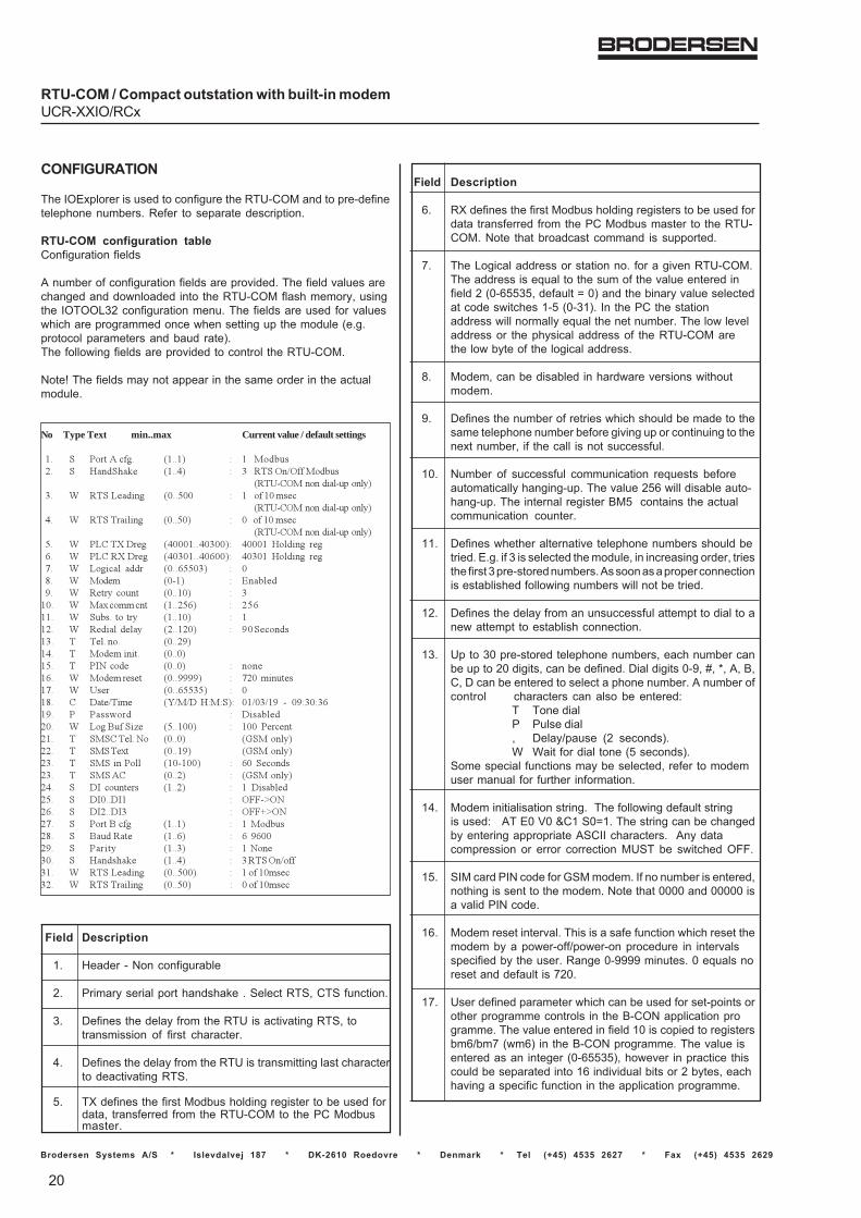
Brodersen Systems A/S * Islevdalvej 187 * DK-2610 Roedovre * Denmark * Tel (+45) 4535 2627 * Fax (+45) 4535 2629
20
RTU-COM / Compact outstation with built-in modemUCR-XXIO/RCx
CONFIGURATION
The IOExplorer is used to configure the RTU-COM and to pre-definetelephone numbers. Refer to separate description.
RTU-COM configuration tableConfiguration fields
A number of configuration fields are provided. The field values arechanged and downloaded into the RTU-COM flash memory, usingthe IOTOOL32 configuration menu. The fields are used for valueswhich are programmed once when setting up the module (e.g.protocol parameters and baud rate).The following fields are provided to control the RTU-COM.
Note! The fields may not appear in the same order in the actualmodule.
No Type Text min..max Current value / default settings
�� � ��������� ����� � � �������� � ��������� ����� � � ���� �! ���������
��"#$ �������%�&#�'���&(��� ) ����*���%�� +��,++ � � ����+�-��
��"#$ �������%�&#�'���&(��� ) �������%&%�� +��,+� � +�������+�-��
��"#$ �������%�&#�'���&(�,� ) �*$��.�/��� �+++����+�++�� �+++�� ��&�%��� ���0� ) �*$��.�/��� �+�+����+0++�� �+�+�� ��&�%��� ���1� ) *��%�&� ���� +��0,,+�� � +2� ) ����- +#�� � 3���&��4� ) ����(� ���� +���+� � ��+� ) ��5��--��� ����,0� � �,0��� ) �����������( ����+� � ���� ) ���%�&� ��&�( �����+� � 4+��������� � ��&����� +���4���� � ����-�%�%�� +��+��,� � �67���� +��+� � �����0� ) ����-������ +��4444� � 1�+�-%������1� ) "��� +��0,,�,� � +�2� $ /���!�%-� 8!�!/�������� +�!+�!�4� #� +4��+��0�4� � ����9��� � /%���&���+� ) *���:����%;� ,���++� � �++� ��������� � ���$���&��7� +��+� <�����&(���� � ������5� +���4� <�����&(���� � ����%����&& �+#�++� � 0+� ��������� � ����$ +���� � <�����&(���� � /6� ������� ����� � �� /%���&���,� � /6+��/6� � ==#> 7�0� � /6���/6� � ==?> 7�1� � �����:��� ����� � ���������2� � :�������� ���0� � 0� 40++�4� � ���%�( ����� � ��7����+� � ��������� ����� � ������ �!������ ) ����*���%�� +��,++� � ������+-����� ) �������%&%�� +��,+� � +�����+-��
Field Description
1. Header - Non configurable
2. Primary serial port handshake . Select RTS, CTS function.
3. Defines the delay from the RTU is activating RTS, totransmission of first character.
4. Defines the delay from the RTU is transmitting last characterto deactivating RTS.
5. TX defines the first Modbus holding register to be used fordata, transferred from the RTU-COM to the PC Modbusmaster.
Field Description
6. RX defines the first Modbus holding registers to be used fordata transferred from the PC Modbus master to the RTU-COM. Note that broadcast command is supported.
7. The Logical address or station no. for a given RTU-COM.The address is equal to the sum of the value entered infield 2 (0-65535, default = 0) and the binary value selectedat code switches 1-5 (0-31). In the PC the stationaddress will normally equal the net number. The low leveladdress or the physical address of the RTU-COM arethe low byte of the logical address.
8. Modem, can be disabled in hardware versions withoutmodem.
9. Defines the number of retries which should be made to thesame telephone number before giving up or continuing to thenext number, if the call is not successful.
10. Number of successful communication requests beforeautomatically hanging-up. The value 256 will disable auto-hang-up. The internal register BM5 contains the actualcommunication counter.
11. Defines whether alternative telephone numbers should betried. E.g. if 3 is selected the module, in increasing order, triesthe first 3 pre-stored numbers. As soon as a proper connectionis established following numbers will not be tried.
12. Defines the delay from an unsuccessful attempt to dial to anew attempt to establish connection.
13. Up to 30 pre-stored telephone numbers, each number canbe up to 20 digits, can be defined. Dial digits 0-9, #, *, A, B,C, D can be entered to select a phone number. A number ofcontrol characters can also be entered:
T Tone dialP Pulse dial, Delay/pause (2 seconds).W Wait for dial tone (5 seconds).
Some special functions may be selected, refer to modemuser manual for further information.
14. Modem initialisation string. The following default stringis used: AT E0 V0 &C1 S0=1. The string can be changedby entering appropriate ASCII characters. Any datacompression or error correction MUST be switched OFF.
15. SIM card PIN code for GSM modem. If no number is entered,nothing is sent to the modem. Note that 0000 and 00000 isa valid PIN code.
16. Modem reset interval. This is a safe function which reset themodem by a power-off/power-on procedure in intervalsspecified by the user. Range 0-9999 minutes. 0 equals noreset and default is 720.
17. User defined parameter which can be used for set-points orother programme controls in the B-CON application programme. The value entered in field 10 is copied to registersbm6/bm7 (wm6) in the B-CON programme. The value isentered as an integer (0-65535), however in practice thiscould be separated into 16 individual bits or 2 bytes, eachhaving a specific function in the application programme.

40113/11_10 21
RTU-COM / Compact outstation with built-in modemUCR-XX/RCX
Brodersen Systems A/S * Islevdalvej 187 * DK-2610 Roedovre * Denmark * Tel (+45) 4535 2627 * Fax (+45) 4535 2629
NOTES/REMARKS
1) Section A, B and C are isolated from each other. The individual analogueinputs are isolated from each other. Due to protection devices in theanalogue inputs the voltage measured from the common (C) terminalsto any other terminals must not exceed ±80V.
2) The polarity at the input must be positive. The common terminalmust be connected to the negative.
3) Input signals exceeding the maximum values MAY CAUSEPERMANENT DAMAGE to the module.
4) External resistor (500 Ohm) to be mounted for ~0-20mA input.Note that the internal resistance must be calculated as parallelto the 500 ohm.
5) Only one analogue input channel is active at a time, the multiplexingis automatic via the built-in micro-controller.The actual scan time for the analogues relates to the CPU loadand hence the selected interval for the application program. Ifthe application program is executed with a short interval theremight not be sufficient time to perform the analogue multiplexingthus resulting in a slow sampling rate (worst case 2 seconds).
Select channel 0 1 0
Convert Sampling time (100-2000 ms)
The analog input is represented by an integer (binary number)from 0 to 4095 depending on the input signal, see table above.
6) Depending on the noise level versus signal level, shielded cablesand/or twisted pairs might be necessary. The shield of the cableshould normally be connected to common (C) of the I/O modules.
7) Register BM 0-511 are cleared at start-up. Registers BM 512-2047are battery backed, the values stored are independent of power andmust therefore be cleared manually if required.
8) The 12V external supply is not isolated from the circuit supplying theelectronics. It is therefore recommended to use an external sourcefor the I/O if the I/O signals are influenced by electrical noise, e.g.from long cables or inductive load.
9) The external output is short circuit protected and overload protected.The maximum current is limited at high ambient temperature.The maximum load current should be de-rated approximately 1%per °C above 25°C.
10) The RTU00 must only be powered from safe low voltage asthere are no isolation provided at the supply input.
Field Description
18. Real time clock adjustment. The actual time in the RTU-COMcan be monitored and adjusted either by entering the time orby copying the PC clock to the RTU-COM.
19. Enabling/disabling password facility in the RTU-COM.
20. Log buffer size. Define the size of log buffer in the range of5 to 100% of 480kB. If changed all data in log is lost.
21. GSM provider SMS Service Center No. Used if sending SMStext messages via GSM modem.
22. SMS text messages. Up to 40 fixed text messages with max.40 characters can be stored in the module. Only 7 bit ASCIIare supported.
23. SMS Poll. Define the frequency of polling the modem forreceived SMS. Range: 10-100s default set to 60s.
24. SMS admittance control. Table with list of mobile phonenumbers accepted to change values via SMS messages. Ifno numbers in table no admittance control enabled (default)
25. Disable/enable the counter function on DI0 and DI1.
26. Define type of wake-up transition for the 2 first inputs.
27 Define type of wake-up transition for the last 2 digital inputs.
28. Programming port settings - Header-Non configurable:
29. Defines the port baud rate. 300, 600, 1200, 2400, 4800,9600 baud is possible. Default= 9600
30. Defines port parity. None, Even, Odd is possible. Thecharacter length is fixed at 8 data bits. No parity is default
31. Programmer serial port handshake. Select RTS, CTSfunctions.
32. Defines the delay from the RTU is activating RTS totransmission of the first character.
33. Defines the delay from transmission of the last characterto deactivating RTS.

Brodersen Systems A/S * Islevdalvej 187 * DK-2610 Roedovre * Denmark * Tel (+45) 4535 2627 * Fax (+45) 4535 2629
22
RTU-COM / Compact outstation with built-in modemUCR-XXIO/RCx
Appendix A
TYPICAL LOG UPLOAD TIME
In general the log upload time depend on the actual data speed used.On modem connections - and specially on GSM modem connections,the log upload time can be very different.Log upload time can be reduced by only uploading data since lastupload. Also reducing the log size, can minimize the log upload time.
The typical values given below is just to give an idea of the log uploadtime.
Application Speed (baud) Type Time
Null Modem/direct RS232 cable 9600 Full upload 33 minutes.
PC with PSTN/RTU with GSM 9600 Full upload 62 minutes.