rts 3430 a - artc - extranet · engineering practices manual civil engineering rts 3430 track...
TRANSCRIPT

Issue A Australian Rail Track CorporationRevision 0 This document is uncontrolled when printedMarch 2006 Page 1 of 22
Engineering Practices Manual
Civil Engineering
Track Reconditioning Guidelines
RTS 3430Issue A, Revision 0
March 2006
1. Scope
This guide has been prepared to assist in the investigation, design and rehabilitationof the existing track formation and ballast.
It is intended to be used in all construction or maintenance activities aimed atmodifying the existing formation conditions.
It is recommended that a geotechnical engineer experienced in track geotechnologyauthorise the formation design.
2. Reason and Nature of Change
Document reissued as ARTC Engineering Practice Manual.
3. Purpose of Track Reconditioning
The purpose of track reconditioning is to reconstruct the track formation and ballastto restore the track structure to a standard appropriate to current track loading.Reconditioning usually involves the removal of rails, sleepers and ballast and apredetermined depth of the existing formation and the reconstruction of thosecomponents to current earthworks standard. Modifications to the track drainage arenecessary at the same time.
Reconditioning is usually carried out because of bearing capacity failure of theformation or a failure of the drainage, but is at times carried out to replace foulballast where local conditions prevent the use of ballast cleaners.
4. Determining the Need to Carry Out Reconditioning
Track improvement requires an adequate investigation. It is important to have aclear idea of what the problem is, and its extent.
Consideration of the need to carry out track reconditioning should be given when

Engineering Practices ManualCivil Engineering RTS 3430Track Reconditioning Guidelines
Issue A Australian Rail Track CorporationRevision 0 This document is uncontrolled when printedMarch 2006 Page 2 of 22
any one of the following features exist:
a) Continue poor track performance, ie. Rapid deterioration of top, or top andline in spite of repeated attempts at resurfacing, ballasting, or ballastcleaning.
b) Visible signs of formation failure, ie. “heaving” beyond the ends of sleepers or between sleepers.
c) “Bog Holes” –Track and ballast fouled and/or with mud actively pumpingthrough the ballast.
When the track is removed and formation lowered to increase height clearances, thecorrect ballast depth must be provided and the reconstruction of the loweredformation should follow the investigation and design principles set out in this guide.
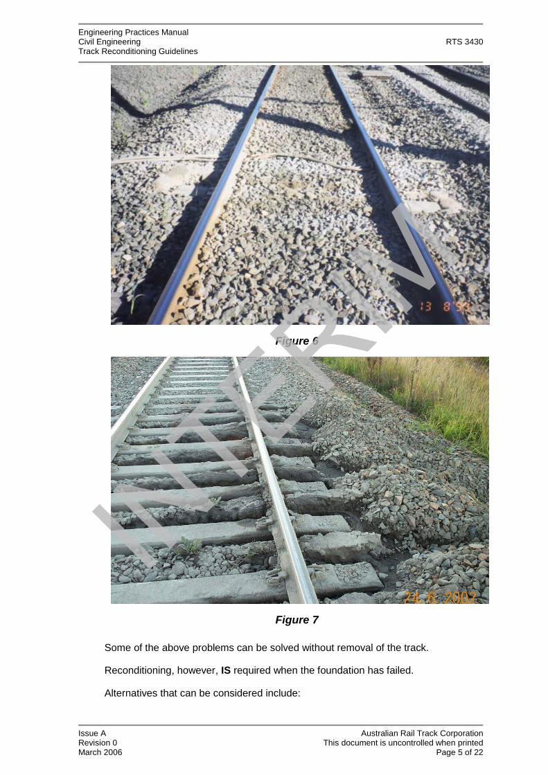
Figures 1, 2, 3, 4, 5, 6 and 7 illustrate examples of track formation problems.
Figure 1

Engineering Practices ManualCivil Engineering RTS 3430Track Reconditioning Guidelines
Issue A Australian Rail Track CorporationRevision 0 This document is uncontrolled when printedMarch 2006 Page 3 of 22
Figure 2
Figure 3

Engineering Practices ManualCivil Engineering RTS 3430Track Reconditioning Guidelines
Issue A Australian Rail Track CorporationRevision 0 This document is uncontrolled when printedMarch 2006 Page 4 of 22
Figure 4
Figure 5
Engineering Practices ManualCivil Engineering RTS 3430Track Reconditioning Guidelines
Issue A Australian Rail Track CorporationRevision 0 This document is uncontrolled when printedMarch 2006 Page 5 of 22
Figure 6
Figure 7
Some of the above problems can be solved without removal of the track.
Reconditioning, however, IS required when the foundation has failed.
Alternatives that can be considered include:

Engineering Practices ManualCivil Engineering RTS 3430Track Reconditioning Guidelines
Issue A Australian Rail Track CorporationRevision 0 This document is uncontrolled when printedMarch 2006 Page 6 of 22
Methods that do not require track removal:
1) Shoulder and crib ballast replacement (Manual and Machine)
2) Cross Drains (see section 4.1)
3) Sledding
4) Ballast Cleaning
5) Lime Slurry Injection
Methods that require track removal:
1) “Skim” Reconditioning (see section 4.2)
2) Formation reconstruction
4.1. Formation Drainage Option
Track conditions may improve sufficiently without reconditioning if drainage of theformation is improved. Cut off drains across the whole track to a level below theballast formation interface will drain depressions in the formation. These cut offdrains or finger drains need to be at intervals of 5m. This solution may avoid costlytrack possession.
Removal of the shoulder ballast and replacement with clean ballast will releasewater trapped in the track profile, and replacement of the crib ballast with cleanballast will improve track performance.
Cess drains must be lowered to below the formation level to permit drainage.
4.2. Skim Reconditioning
Where the formation has not failed, there is no original capping, and it is possible toraise the track, skim reconditioning is a viable solution.
The track is removed and the clean top ballast excavated. The foul bottom ballast isgraded and compacted to form a structural capping layer. The track is then relaidand ballasted.
This method is used when replacing timber sleepers with concrete sleepers.
5. Investigations Prior to Track Reconditioning
The causes of the track formation failure and details of the subsurface conditionsshould not be assumed. All reconditioning projects should have a geotechnicalinvestigation carried out by an experienced geotechnical engineer at early planningstages.
The typical geotechnical investigation will consider the following:
Subsurface conditions – depth and condition of ballast, capping andsubgrade.
Determination of the cause of failure – foundation failure, ineffective

Engineering Practices ManualCivil Engineering RTS 3430Track Reconditioning Guidelines
Issue A Australian Rail Track CorporationRevision 0 This document is uncontrolled when printedMarch 2006 Page 7 of 22
drainage, rock pumping.
Adjoining structures–effect on platform footings, if any.
Reconditioning recommendations –ballast clean, skim (remove ballast only)or full reconditioning.
Reconditioning design–depth of layers etc.
Subgrade treatment–geosynthetics, rock fill, geocell etc.
Drainage needs.
5.1. Investigation Procedures
The basic components of an adequate investigation of track constructed on clay orfill consist of the following procedures and aims:
a) Excavation of test pits at regular intervals (10 to 20m, alternate Up & DownSide, in the four foot, and at obviously failed locations) to determine:
- The depth and condition of the ballast.
- The existence of other ballast materials.
- The existence and condition of capping.
- The condition and type of subgrade.
- The degree of saturation of all materials.
- Information about the interface profile, if visible, to indicate the degreeof rutting or consolidation.
Investigations should be located between two sleepers and the outside rail orin the 4ft and extend to below the formation level or about 1.2m below therail level. See Figure 8.
Excavations across the whole track between sleepers provide the mostinformation, especially about the formation profile, but are expensive andintrusive and should be done less frequently as a control.
b) Insitu strength tests using Dynamic Cone Penetrometer (DCP) should beconducted close to the rail. Tests should start from below the ballast andcontinue to a depth of 2.5m below rail level to provide an estimate of theinsitu CBR value.
c) Samples of the subgrade should be selected for classification testing and toassist in the design of graded filters (sub ballast) or geotextiles or todetermine if stabilizing materials will assist in improving subgradeperformance. Samples of the top and bottom ballast should be taken todetermine ballast recovery, should the material be recycled. Samples shouldbe a minimum of 30kg.
d) A description of the degree of saturation of the track should be recorded, asshould details of the cess drainage and any system existing and an

Engineering Practices ManualCivil Engineering RTS 3430Track Reconditioning Guidelines
Issue A Australian Rail Track CorporationRevision 0 This document is uncontrolled when printedMarch 2006 Page 8 of 22
evaluation of its condition.
e) Survey details of the track, cess drain inverts, culvert inverts and adjacentareas, (and beyond boundary if necessary) are necessary for design offuture drainage.
Figure 8 – Ballast depth and formation investigation for reconditioning
6. Track Formation Design
6.1. Basic Design Model
The basic design model consists of the standard 300mm of ballast below thesleeper supported by 150mm of capping material. This is satisfactory provided theunderlying material will provide sufficient support. (Relate to TDS 11).
Where the formation consists of hard rock or concrete the ballast thickness must notbe less than 250mm otherwise ballast degradation and rock abrasion will accelerate.(Relate to TDS 11).
For track on soil or fill, the material immediately beneath the capping layer(structural fill) is required to have a soaked Californian Bearing Ratio (CBR) ≥8.(See Figure 9). The required thickness of this material varies depending on thequality of the founding material. The thickness “H” of structural fill/material is recommended for the following founding material:
Founding Material–CBR Thickness “H” (mm) Structural Material
≥3 500
1-3 1000
Dynamic Cone Penetrometer (DCP) testing is therefore required to 2.5m below rail.A correlation between DCP tests and CBR is provided in Appendix 1.
Ballast
Capping? –wet/moist? condition?
Foul Ballast?(Wet/moist/dry, foulingmaterial, ballast type)
DCP Testfrom top of capping to2.0m below rail level
Formation–type ofmaterial, moisturecondition, hard/soft?
Subgrade Condition?
Excavation infour foot oroutside rail

Engineering Practices ManualCivil Engineering RTS 3430Track Reconditioning Guidelines
Issue A Australian Rail Track CorporationRevision 0 This document is uncontrolled when printedMarch 2006 Page 9 of 22
7. Capping Materials
7.1. General
Capping as specified in ARTC standard TDS 12 is used for some or all of thefollowing reasons:
To improve track support. (Generally a layer 150mm thick is sufficient fornormal conditions with increased thickness for soft subgrade).
To fill in irregular over-break situations in rock excavations to assist indrainage.
To provide a drainage barrier to shed storm water from subgrade.
The performance of the capping depends on the quality of the material and thequality of its compaction on placement. The material needs to comply strictly withthe requirements of TDS 12 and to be compacted in accordance with RCP 01 toprovide the ‘Barrier/Support’ features expected.
7.2. Flexible Impermeable Capping
The properties specified for capping of this type are designed to provide a flexibleimpermeable granular of high strength. For this material to perform correctly theproperties of the material supplied must strictly comply with the requirements of TDS12 for flexible impermeable capping. This layer is designed to seal the formationand shed any surface water. Material suppied as DGB20, or similar, in accordancewith specifications prepared for the RTA of NSW do not necessarily comply and willnot provide a seal to the formation. The closest road specification to railrequirements is “Road base for unsealed roads”. Material to beused as capping ofthis type should be tested for compliance prior to use.
It is also very important that the correct compaction levels are obtained. Poorly
Ballast depth–see TDS 11

Engineering Practices ManualCivil Engineering RTS 3430Track Reconditioning Guidelines
Issue A Australian Rail Track CorporationRevision 0 This document is uncontrolled when printedMarch 2006 Page 10 of 22
compacted capping will become saturated quickly, foul the track and become thecause of further track and ballast problems.
7.3. Sub-Ballast
Where the foundation consists of free draining materials such as rock fill or sand asub-ballast may be more appropriate than an impermeable capping.
Sub-ballast is not impermeable and is designed as a filter material to limit fouling bysubgrade material and to prevent itself from fouling the ballast. Its purpose is to:
Spread vertical load from the ballast.
Prevent migration of fines from the subgrade.
Permit migration of moisture.
The grading of the sub-ballast is important and must be specifically designed for aparticular subgrade and ballast. Laboratory testing of both the subgrade and theballast is required to be able to design a grading for sub-ballast.
The performance of the sub-ballast is not destroyed by saturation as is that of thecapping and it is much more easily compacted. It may provide a better solution thancapping in areas where the subgrade is constantly wet due to, say, a spring or insoft rock formation situations.
7.4. Semi Rigid Capping
In situations where it is difficult to obtain material complying with the specificationsfor impermeable capping and the formation conditions are relatively stiff a semi rigidcapping may be appropriate. It is also appropriate as a capping over soft friablerock foundations. This material may consist of a stabilized material and propertiesare specified in TDS 12.
The use of this material over soft formation is not recommended as it will crack onflexure and rapidly cause track pumping problems. It is advised that thoroughgeotechnical investigation and analysis be performed before choosing this type ofcapping.
8. Drainage
The success of any track or reconstructed track formation is governed by theeffectiveness of the drainage of water from the ballast above the capping and thesubsoil water beneath the capping. An effective surface drainage system must beconstructed as part of all reconditioning. For surface drainage to be effective,grades must be uniform, without local hollows. Ponding of water in cess drains orsurface drains produces gradual deterioration of the formation strength.
Reconditioning must not create a condition where water ponds beneath the track.
If the investigation discovers saturated conditions a subsoil drainage system mustbe installed. Subsoil drainage is required to:
Drain any porous subsoil material.
Lower water table where it is near the ground surface.

Engineering Practices ManualCivil Engineering RTS 3430Track Reconditioning Guidelines
Issue A Australian Rail Track CorporationRevision 0 This document is uncontrolled when printedMarch 2006 Page 11 of 22
Reduce pore water pressure due to train loadings in rock foundations orartesian pressure eg.-springs.
Subsoil drainage systems require headwalls at the outlets and flushing points formaintenance. These features need to be clearly visible and signposted.
More detailed information on surface and subsoil drains is available in ARTCEngineering Practice RTS 3433.
9. Geosynthetics
CAUTION
Geotextiles are not Magic
They cannot be used to short cut the project
or make up for poor construction materials
Geotextiles have been used extensively in track reconditioning for some yearsbecause it was believed that benefit could be gained in subgrade support andseparation of the ballast from the capping. More recent experience andinvestigations reveal that the geotextile provides little benefit unless usedappropriately and may also create problems. The most appropriate uses ofgeosynthetics in track formation are:
Filtration and separation.
Subgrade support.
The geotextiles for these purposes have significantly different properties and thebetter performance in one means a reduced performance in the other.
9.1. Ballast/Capping Separation
Geotextile was originally placed beneath the ballast in the belief that it would reducefouling of the ballast by fine material from the formation. In other cases it wasplaced because the capping had not been sufficiently compacted. However,research of ballast performance has shown that where the formation and cappingare constructed properly the major contribution to ballast fouling is from ballastbreakdown and contamination from the surface. The presence of geotextiletherefore fails to protect the ballast from these contaminations. Local experiencehas shown in many cases that the material above the geotextile has been morefouled than below.
Furthermore the geotextile suffers severely from abrasion by the ballast and veryquickly loses its separating capabilities. Where the geotextile has been used in wetand soft conditions or when capping has not been compacted adequately, the highdynamic loads from rail traffic induces extreme pressures at the ballast formationinterface and the filtering action of the geotextile is negligible.
Ballast cleaning operations have also been severely hampered by the presence ofthe geotextile.
It is therefore not recommended that geotextile be placed beneath ballast atthe ballast/capping interface.

Engineering Practices ManualCivil Engineering RTS 3430Track Reconditioning Guidelines
Issue A Australian Rail Track CorporationRevision 0 This document is uncontrolled when printedMarch 2006 Page 12 of 22
A geotextile is necessary, however, between two materials of significantly differentgrading. When placing capping or sub-ballast material over coarse rock fill ageotextile is necessary to prevent the fine material of the capping from falling intothe voids of the coarse fill.
Figure 10– Excavated geotextile showing complete “clogging” in service
9.2. Filtration
Geotextiles are used to great advantage in subsoil drainage systems and the costlyprocess of graded aggregate filters have been avoided. A geotextile wrappedaround coarse aggregate or a slotted pipe provides substantial cost savings.
It is, however, necessary to sample and test the soils in which the subsoil drain willbe placed to determine the appropriate geotextile to use. Some soils are not filteredby all geotextiles. Soils with high content of fine silts and clays require closeinvestigation and in some cases cannot be drained by subsoil drains wrapped ingeotextile.
The important properties of the geotextile are its filtering properties and the strengthproperties so that the geotextile will maintain its integrity during the constructionprocess. The properties set out in the following tables are for average conditions.Where there is doubt about the soil/geotextile compatibility, a geotechnicalinvestigation is required.
9.3. Reinforcement
A geotextile is placed below the structural fill to reduce subgrade deformation due tothe load and to reduce the amount of structural fill required. A geotextile for such apurpose is required to have a high tensile strength and low elongation and todevelop good bond with the contact material.
The best material for this purpose is a geogrid and it is recommended in very soft

Engineering Practices ManualCivil Engineering RTS 3430Track Reconditioning Guidelines
Issue A Australian Rail Track CorporationRevision 0 This document is uncontrolled when printedMarch 2006 Page 13 of 22
areas. Other geotextiles providing good reinforcement are the woven type fabrics orbonded fabrics. The properties recommended as minimum for track work are givenin Section 9.4 below.
9.4. Properties of Geotextiles in Track Projects
9.5. Subsoil Drainage
Property Test Method Value
Tearing Strength, Trapezoidal * AS 3706.3 200N min
Burst Strength, CBR Method * AS 3706.4 1700N min
Puncture Resistance, Drop Cone * AS 3706.5 d500 = 33.5mm MaxH50 = 900mm Min
Pore Size * AS 3706.7 240 max
Permittivity AS 3706.9 3.4 sec* min
* - Important when used as a separation for rock fill
9.6. Subgrade Reinforcement (Below Capping)
Property Test Method Value
Tensile Strength, Wide Strip AS 3706.2 25KN/m min peak
Elongation at Peak Strength AS 3706.2 25% max
Burst Strength CBR Method AS 3706.4 2800N min
Permittivity AS 3706.9 0.12 sec-1 min
9.7. Properties of Geogrids
A geogrid is specifically designed to provide tensile reinforcement to the tracksubstructure. Geogrids are superior to geotextiles in this function because of theirhigher modulus and tensile strength and the performance is not destroyed by coarseaggregate.
The geogrid selection should be on the basis of the grading of the material incontact with it ant the grid opening size is related to the maximum size of theaggregate with which it interlocks. The manufacturers provide a selection criteria fortheir products for the various uses.
The recommended minimum strength is 20KN/m transverse and 20KN/mlongitudinal to the track. The interlocking with aggregates is important. Whenselecting a geogrid, careful attention should be paid to the profile and rigidity of thegrid webbing. A geogrid with a square web profile and high rigidity will perform wellin interlocking with aggregate.
10. Track Reconstruction Solutions
Reconditioning is usually required because the subgrade has not met the abovecriteria. Methods of improving the performance of the existing subgrade materialneed to be considered in the planning of the reconditioning. The following optionsare suggestions only and each situation needs to be assessed by a geotechnicalengineer for conditions peculiar to the site.

Engineering Practices ManualCivil Engineering RTS 3430Track Reconditioning Guidelines
Issue A Australian Rail Track CorporationRevision 0 This document is uncontrolled when printedMarch 2006 Page 14 of 22
10.1. Reconstruction by Structural Fill Methods
Reconstruction of the formation is conducted by excavation of unsuitable materialand replacement with suitable material to suit the basic design model. See Figure 9.
For soft subgrade this option would require sufficient time and space to permit theremoval and replacement of what could consist of a substantial amount of materialto provide the support defined in the model.
If, however, investigations indicate that the subgrade has a CBR of 8 or greater andthat track failure is due to loss of the frictional properties of the ballast due to poordrainage only, minimal excavation is necessary to remove the thin layer of softmaterial immediately beneath the ballast. In conjunction with the necessaryreconstruction of effective drainage, a reduced thickness of structural fill can beused in these situations.
The new material must comply with the requirements of ARTC Standards C1100and TS 3422 and the work required includes preparation and compaction asnormally applies to earthworks construction. A capping layer of 150mm (min) isrecommended unless the structural fill also meets the requirements of TS 3422, inwhich case the fill would continue to below the ballast.
10.2. Reconstruction Using Reinforcements of Rock Fill and Geosynthetics
The use of geotextiles and/or geogrids, geocells and rock fill can assist to reducethe amount of excavation and fill material especially in soft subgrade.
10.3. For Subgrade with CBR = 3-8
Where the subgrade has been found to have an insitu CBR of between 3 and 8 ageotextile below a higher grade imported fill material will reduce the excavationnecessary. The fill material is recommended to have CBR of at least 20 at 100%standard compaction and a minimum thickness of 350mm. The geotextilereinforcement must be a high strength, low elongation type material or the benefitswill not be realized. See Figure 11.
Figure 11–Geogrid Reinforcement
HCapping 150mm (min)
Subgrade CBR = 3–8 use GeotextileSubgrade CBR = 1–3 use Geogrid
1.5
1
Ballast depth–see TDS 111:30
Geotextileseparation
H=350mm, Subgrade CBR = 3–8H=500mm, Subgrade CBR = 1 - 3
1m (min) 1m (min)

Engineering Practices ManualCivil Engineering RTS 3430Track Reconditioning Guidelines
Issue A Australian Rail Track CorporationRevision 0 This document is uncontrolled when printedMarch 2006 Page 15 of 22
10.4. For Subgrade with CBR = 1-3
Where the subgrade has been found to have a CBR of between 1 and 3 a geogrid isrecommended in place of a geotextile at the subgrade level. The samerecommendations for the type of fill as in Section 11.3.1 apply with a thickness of500mm. See Figure 11.
10.5. For Subgrade with CBR = 1 or Less (Rock Fill)
Where the subgrade had been found to have a CBR of 1 or less it will be necessaryto use coarse rock fill to reduce the amount of excavation. A minimum excavation of500mm is recommended. Obtain geotechnical advice for resolving these conditions.
Coarse rock fill, 50-150mm in size (no fine material) is tipped or rolled into the softmaterial. More is added until the rock fill no longer penetrates the mud and thesurface is just free of mud. A geogrid is then laid and filling continued with rock fillup to the underside of capping, with appropriate static rolling. No wheeled ortracked machinery should be permitted on the subgrade until sufficient rock fill hasbeen placed to support it. An additional layer of geogrid should be added where thefilling exceeds 500mm.
The surface of the rock fill must be covered with a geotextile for separation betweenrock fill and capping. See Figure 12.
Figure 12–Rockfill Reinforcement
10.6. For Subgrade with CBR = 1 or Less (Geocells)
An alternative to the solutions outlined in 10.3.3 is to install Geocells to improve theload support capacity of soft subgrade. It is often recommended for swampyconditions where the ground water is close to the surface. Geocells consist of anarray of plastic hexagonal cells infilled with granular material. These are installedimmediately below the ballast and filled with ballast. Geocells are available inpanels 2.44m x 6.1m with thickness varying between 102 and 203mm.
Ballast depth–see TDS 11
H=500mm(min)Capping 150mm (min)
Rock rolled intosoft formation
1.5
1
Ballast depth–see TDS 11
Geogrid at base
1:30
Additional layerof Geogrid whereH>500mm
Geotextileseparation
Rockfill50 to 150mmstatic rolled Subgrade CBR<1
1m (min) 1m (min)

Engineering Practices ManualCivil Engineering RTS 3430Track Reconditioning Guidelines
Issue A Australian Rail Track CorporationRevision 0 This document is uncontrolled when printedMarch 2006 Page 16 of 22
The thickness and number of geocell layers must be individually designed for eachparticular situation. An excavation is made to the designed level of the geocellbase. A geotextile is laid over the excavation to minimize the transmission of finesthrough the geocell into the ballast. The geocell is laid out, filled and the infill lightlycompacted. No capping is required above the geocell, however in situations wherethe subgrade needs to be protected from surface water, an impermeablegeomembrane may be installed at the geocell base instead of a geotextile.Impermeable membranes are not required when Geocells are installed in swampyground conditions. See Figure 13.
Figure 13–Geocell Reinforcement, Formation CBR<1
It should be noted that you still need to install the depth of ballast specified in TDS11 above the geocell. The geocell installation is a solution to provide support, not toreduce ballast.
11. Chemical Stabilisation
Stabilisation of subgrade is the improvement of the subgrade by mixing in lime orinjection of lime or a lime/fly ash mixture.
Lime stabilisation is very relevant for high plasticity clays because of the reaction oflime with the clay minerals and can be used to reduce the shrink/swell behaviour ofactive soils. For the best results the subgrade must be scarified and lime spreadand mixed uniformly. This requires adequate track possession and work space.
Lime injection methods require numerous inspection points to guarantee that thelime is uniformly distributed in the subgrade.
For less plastic clays the effect of lime is more a cementation action that is notstrong. Procedures are available for lime and fly ash injection that provides animprovement in strength of the subgrade. These procedures provide high-pressureinjection to significant depths at close spacing.
In general, lime injection or stabilisation is not recommended without sufficientinvestigation to support their use. Geotechnical advice and laboratory testing isnecessary to determine the appropriate percentage of lime for the soil in question.
Stabilisation by the injection of cement slurry is not recommended.
Other chemicals are offered to assist in stabilisation of the subgrade and need to beevaluated as to practicability or effectiveness. Obtain geotechnical advice to assistin the evaluation of products that are being marketed as possible stabilisation
1.5
1
Geocell 100 to 200 deep
1:30 Ballast depth–see TDS 11
Geotextile or Impermeablegeomembrane

Engineering Practices ManualCivil Engineering RTS 3430Track Reconditioning Guidelines
Issue A Australian Rail Track CorporationRevision 0 This document is uncontrolled when printedMarch 2006 Page 17 of 22
measures.
12. Construction Issues
1) Minimise or eliminate construction traffic over exposed subgrade material.
After excavation of the ballast the formation is usually not firm and thepassage of wheeled or tracked machinery will cause significant additionaldamage.
Where possible, the construction method must be designed to avoidtrafficking over the exposed formation. Excavating spoil by placingexcavating machinery on adjacent undisturbed track or ground and pushingnew fill in front of construction equipment is necessary when dealing with softformation. The structure of some clay is destroyed by the remoulding actionof construction equipment. This damage to the soil structure is permanentand may reduce the strength and affect the future performance of theformation.
2) Compact new fill in layers no deeper than 200mm loose. Thinner for lightcompaction equipment.
3) Use proper compaction equipment and compact to specified density.
4) Construct the correct cross fall.
5) Construct adequate drainage.
13. Rock Foundation
The investigation of track on a rock base follows the basic steps set out earlier.Where there is evidence of track fouling as a result of foundation problems and theinvestigation reveals that the track is constructed on hard shale or sandstone, thepotential of foundation rock pumping must also be investigated by geotechnicalpersonnel.
13.1. Foundation Rock Pumping
Foundation rock pumping occurs in horizontally bedded rock under track work wherethe cyclic loading conditions cause deflections of the rock strata and abrasion alongrock bedding planes. In the presence of water, fine material, resulting from theabrasive action, is forced through fractures in the rock and contaminates the ballast.Depending on drainage conditions at the track level, isolated cones of rock fines willexist in the ballast or the ballast will eventually be completely fouled with mud. SeeFigure 14.
This pumping can exist up to 2.0m below the track formation level.
In cases where foundation rock pumping is believed to be occurring more detailedinvestigation methods are recommended with a geological evaluation of whateverrock is exposed in adjacent cuttings. The cores would be examined for signs ofabrasion at bedding planes to determine at which depth this is taking place. Thistype of investigation must be carried out by geotechnical engineers or geologistsexperienced with this problem.
When the fouling of ballast due to pumping is severe and the track geometry is

Engineering Practices ManualCivil Engineering RTS 3430Track Reconditioning Guidelines
Issue A Australian Rail Track CorporationRevision 0 This document is uncontrolled when printedMarch 2006 Page 18 of 22
badly affected remedial measures to address rock pumping are required. Thepresence of water close to the formation level is a major contributor to the problemand deep drains are necessary to control the pumping. These drains may need tobe in excess of 1m below the formation.
Alternative solutions to reconditioning may need to be considered where deepdrains cannot be achieved. These solutions may include structural concrete slabsand ground anchors and specialist geotechnical and structural advice is required.
Figure 14–Bedrock Formation pumping mechanism
Figure 15–Example of Bedrock Formation pumping
Cavity caused by abrasion,opens and closes with loadingejecting water and fines
Cavities can exist at depths of2m below formation
Vertical fracture due toflexing or naturaldiscontinuity
Sandstone/Siltstoneor shale
Bedrock separation Bedrock flexesunder load
Pumping and fouling of the track occursprimarily in the presence of water
Bedrock fines (sand, silt and clay)are pumped into ballast and cess
Volcano mound of silt and claycaused by ejection of finesunder pressure

Engineering Practices ManualCivil Engineering RTS 3430Track Reconditioning Guidelines
Issue A Australian Rail Track CorporationRevision 0 This document is uncontrolled when printedMarch 2006 Page 19 of 22
13.2. Irregular Rock Excavation
Track reconditioning may be required because of the fouling of the ballast in rockfoundation areas due to failure of the capping or abrasion of the rock. In rockcutting s where the excavated rock surface is irregular water can be trapped indepressions under the track. This condition will produce accelerated abrasion of thesurface of the rock formation and fouling of the ballast. This situation may also ariseduring the reconditioning exercise where rock has been removed by ripping orhydraulic rock breaker.
It is important to ensure that there is a uniform cross fall on the top of the rockformation. In these situations any over-break or depression should be filled withmaterial with characteristics as close as possible to those of the rock. A cementstabilized road base material, semi rigid capping or roller compacted dry concreteare satisfactory. Layers of cement stabilized material need to be greater than 50mmto prevent disintegration under traffic.

Engineering Practices ManualCivil Engineering RTS 3430Track Reconditioning Guidelines
Issue A Australian Rail Track CorporationRevision 0 This document is uncontrolled when printedMarch 2006 Page 20 of 22
Appendix 1
Dynamic Cone Penetrometer (DCP)–Guide to Use and Interpretation
The dynamic cone penetrometer (DCP) has become a valuable tool in geotechnicalengineering to identify soft material and the boundary between suitable and unsuitablematerial. Because of past correlations by Scala (1956) and the Australian Road ResearchBoard (ARRB, 1973) a measure of soil strength can be found. Scala’s work was carried out predominantly on clays and the report by ARRB was for flays in the Bankstown area.
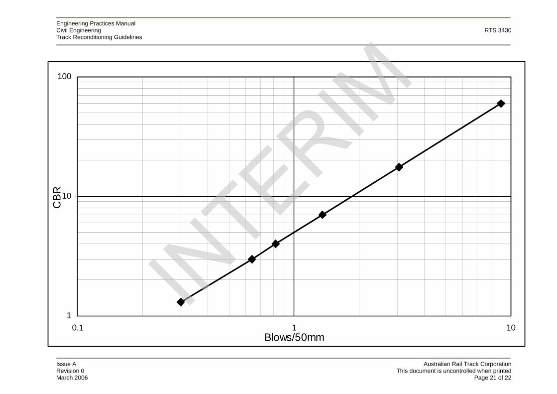
The results of the dynamic cone penetrometer are recorded on the attached record sheetas blows for 50mm of penetration and using the following graph, an equivalent CalifornianBearing Ratio (CBR) can be obtained.
For clay material a reasonable level of confidence is possible, however with sands andashes little correlation exists to obtain shearing or bearing capacity values.
The results obtained from layers of sand or ash will indicate much lower resistance topenetration than for clay but do not indicate correspondingly low bearing capacities.Experience in geotechnical engineering is necessary to make reliable interpretation of lowDCP results in ashes and sand.
The information from the DCP sounding in blows per 50mm is plotted on a linear scalewith depth and correlated if possible with information from boreholes or test pits to identifycritical layers.
Consistently high values in excess of 3 blows/50mm over 350-500mm can be interpretedas a layer of material that may provide good track support. Inconsistent values indicatenon homogeneous material and the possibility of doubtful support. Rocky fill material willprovide extreme variations and needs to be interpreted carefully.
Engineering Practices ManualCivil Engineering RTS 3430Track Reconditioning Guidelines
Issue A Australian Rail Track CorporationRevision 0 This document is uncontrolled when printedMarch 2006 Page 21 of 22
1
10
100
0.1 1 10Blows/50mm
CB
R

Engineering Practices ManualCivil Engineering RTS 3430Track Reconditioning Guidelines
Issue A Australian Rail Track CorporationRevision 0 This document is uncontrolled when printedMarch 2006 Page 22 of 22
Project No.: ……………………….
DYNAMIC CONE PENETROMETER TESTProject: ………………………………..…………………………………………. Date: …..………………………………..…………….
Feature: ………………………………..…………………………………………. Tested by: …..………………………………..…………….
Location: ………………………………..…………………………………………. Supervisor: …..………………………………..…………….
Hole No.
Ground Level (m)
Number of Blows per 50mmDepth below groundlevel (m) 0.000 +2.000 +4.000 0.000 +2.000 +4.000 0.000 +2.000 +4.000 0.000 +2.000 +4.000
0.000 - 0.050
0.050 - 0.100
0.100 - 0.150
0.150 - 0.200
0.200 - 0.250
0.250 - 0.300
0.300 - 0.350
0.350 - 0.400
0.400 - 0.450
0.450 - 0.5000.500 - 0.550
0.550 - 0.600
0.600 - 0.650
0.650 - 0.700
0.700 - 0.750
0.750 - 0.800
0.800 - 0.850
0.850 - 0.900
0.900 - 0.950
0.950 - 1.000
1.000 - 1.050
1.050 - 1.100
1.100 - 1.150
1.150 - 1.200
1.200 - 1.250
1.250 - 1.300
1.300 - 1.350
1.350 - 1.400
1.400 - 1.450
1.450 - 1.500
1.500 - 1.550
1.550 - 1.600
1.600 - 1.650
1.650 - 1.700
1.700 - 1.750
1.750 - 1.800
1.800 - 1.850
1.850 - 1.900
1.900 - 1.950
1.950 - 2.000