rram-mct/e2 - operation manual
TRANSCRIPT
rram-mcte2_g_en_100
RRAM-MCT/E2
Train audio exchange unit according to UIC568
Operation manual
Version 1.00
RRAM-MCT/E2
rram-mcte2_g_en_100 2/31
AMiT, spol. s r.o. does not provide any warranty concerning the contents of this publication and reserves the right to change the documentation without obligation to inform anybody or authority about it.
This document can be copied and redistributed under following conditions:
1. The whole text (all pages) must be copied without any changes. 2. All redistributed copies must retain the AMiT, spol. s r.o. copyright notice
and any other notices contained in the documentation. 3. This document must not be distributed for purpose making of profit. The names of products and companies used herein can be trademarks or registered trademarks of their respective owners.
AMiT is a registered trademark.
Copyright (c) 2013, AMiT, spol. s r. o.
Producer: AMiT, spol. s r. o. Naskové 3/1100, 150 00 Praha
www.amit.cz
Technical support: [email protected]
RRAM-MCT/E2
3/31 rram-mcte2_g_en_100
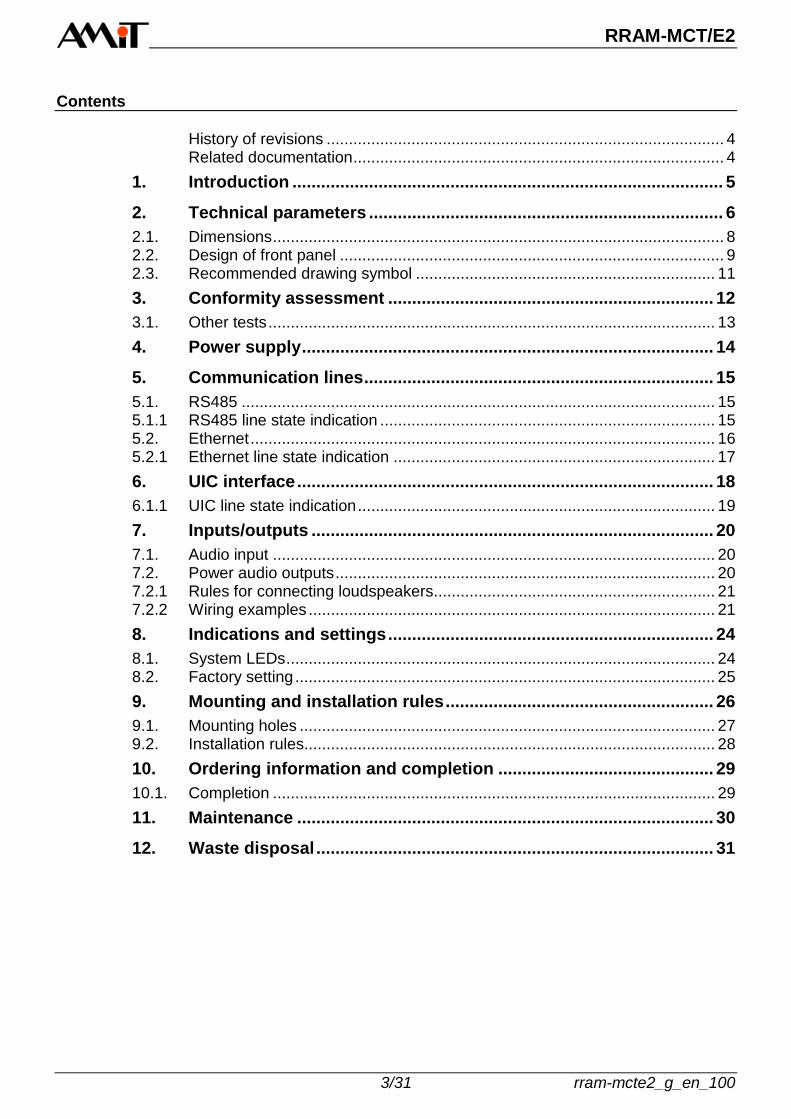
Contents
History of revisions ......................................................................................... 4 Related documentation ................................................................................... 4
1. Introduction .......................................................................................... 5
2. Technical parameters .......................................................................... 6
2.1. Dimensions ..................................................................................................... 8 2.2. Design of front panel ...................................................................................... 9 2.3. Recommended drawing symbol ................................................................... 11
3. Conformity assessment .................................................................... 12
3.1. Other tests .................................................................................................... 13
4. Power supply ...................................................................................... 14
5. Communication lines ......................................................................... 15
5.1. RS485 .......................................................................................................... 15 5.1.1 RS485 line state indication ........................................................................... 15 5.2. Ethernet ........................................................................................................ 16
5.2.1 Ethernet line state indication ........................................................................ 17
6. UIC interface ....................................................................................... 18
6.1.1 UIC line state indication ................................................................................ 19
7. Inputs/outputs .................................................................................... 20
7.1. Audio input ................................................................................................... 20 7.2. Power audio outputs ..................................................................................... 20
7.2.1 Rules for connecting loudspeakers ............................................................... 21 7.2.2 Wiring examples ........................................................................................... 21
8. Indications and settings .................................................................... 24
8.1. System LEDs ................................................................................................ 24
8.2. Factory setting .............................................................................................. 25
9. Mounting and installation rules ........................................................ 26
9.1. Mounting holes ............................................................................................. 27 9.2. Installation rules............................................................................................ 28
10. Ordering information and completion ............................................. 29
10.1. Completion ................................................................................................... 29
11. Maintenance ....................................................................................... 30
12. Waste disposal ................................................................................... 31

RRAM-MCT/E2
rram-mcte2_g_en_100 4/31
History of revisions
Document name: rram-mcte2_g_en_100.pdf
Author: Martin Polášek
Revision Date Changes
100 12. 7. 2013 New document
Related documentation
1. Application Note AP0037 – Principles of using Ethernet network file: ap0037_en_xx.pdf

RRAM-MCT/E2
5/31 rram-mcte2_g_en_100
1. Introduction
RRAM-MCT/E2 is a train audio exchange unit with UIC interface, audio input, built-in power audio amplifier, two Ethernet interfaces and single M12 interface. 1 × UIC interface 1 × RS485 interface 1 × audio input 2 × Ethernet interface 2 × power audio output Power supply voltage 24 V DC Mounting into panel Handset with magnetic holder 7 × illuminated control button Functionality according to UIC568 Design according to EN 50155:2007
Basic features
RRAM-MCT/E2
rram-mcte2_g_en_100 6/31
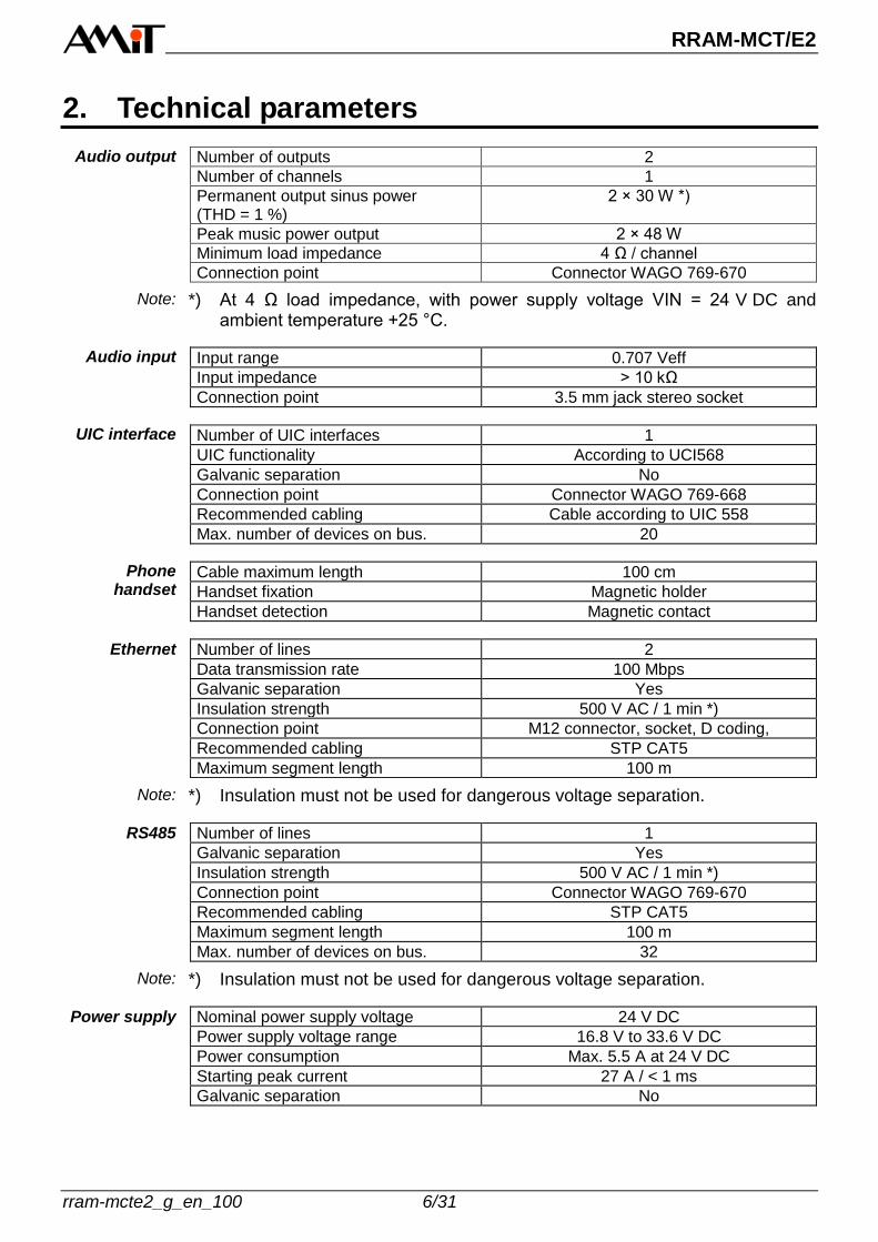
2. Technical parameters
Number of outputs 2
Number of channels 1
Permanent output sinus power (THD = 1 %)
2 × 30 W *)
Peak music power output 2 × 48 W
Minimum load impedance 4 Ω / channel
Connection point Connector WAGO 769-670
*) At 4 Ω load impedance, with power supply voltage VIN = 24 V DC and ambient temperature +25 °C.
Input range 0.707 Veff
Input impedance > 10 kΩ
Connection point 3.5 mm jack stereo socket
Number of UIC interfaces 1
UIC functionality According to UCI568
Galvanic separation No
Connection point Connector WAGO 769-668
Recommended cabling Cable according to UIC 558
Max. number of devices on bus. 20
Cable maximum length 100 cm
Handset fixation Magnetic holder
Handset detection Magnetic contact
Number of lines 2
Data transmission rate 100 Mbps
Galvanic separation Yes
Insulation strength 500 V AC / 1 min *)
Connection point M12 connector, socket, D coding,
Recommended cabling STP CAT5
Maximum segment length 100 m
*) Insulation must not be used for dangerous voltage separation.
Number of lines 1
Galvanic separation Yes
Insulation strength 500 V AC / 1 min *)
Connection point Connector WAGO 769-670
Recommended cabling STP CAT5
Maximum segment length 100 m
Max. number of devices on bus. 32
*) Insulation must not be used for dangerous voltage separation.
Nominal power supply voltage 24 V DC
Power supply voltage range 16.8 V to 33.6 V DC
Power consumption Max. 5.5 A at 24 V DC
Starting peak current 27 A / < 1 ms
Galvanic separation No
Audio output
Note:
Audio input
UIC interface
Phone handset
Ethernet
Note:
RS485
Note:
Power supply
RRAM-MCT/E2
7/31 rram-mcte2_g_en_100
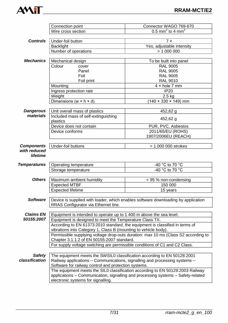
Connection point Connector WAGO 769-670
Wire cross section 0.5 mm2 to 4 mm2
Under-foil button 7 ×
Backlight Yes, adjustable intensity
Number of operations > 1 000 000
Mechanical design To be built into panel
Colour cover RAL 9005 Panel RAL 9005 Foil RAL 9005 Foil print RAL 9010
Mounting 4 × hole 7 mm
Ingress protection rate IP20
Weight 2.5 kg
Dimensions (w × h × d) (140 × 330 × 149) mm
Unit overall mass of plastics 452,62 g
Included mass of self-extinguishing plastics
452,62 g
Device does not contain PUR, PVC, Asbestos
Device conforms 2011/65/EU (ROHS) 1907/2006EU (REACH)
Under-foil buttons > 1 000 000 strokes
Operating temperature -40 °C to 70 °C
Storage temperature -40 °C to 70 °C
Maximum ambient humidity < 95 % non-condensing
Expected MTBF 150 000
Expected lifetime 15 years
Device is supplied with loader, which enables software downloading by application RRAS Configurator via Ethernet line.
Equipment is intended to operate up to 1 400 m above the sea level.
Equipment is designed to meet the Temperature Class TX.
According to EN 61373:2010 standard, the equipment is classified in terms of vibrations into Category 1, Class B (mounting to vehicle body).
Permissible supplying voltage drop-outs duration: max 10 ms (Class S2 according to Chapter 3.1.1.2 of EN 50155:2007 standard.
For supply voltage switching are permissible conditions of C1 and C2 Class.
The equipment meets the SWSIL0 classification according to EN 50128:2001 Railway applications – Communications, signalling and processing systems – Software for railway control and protection systems.
The equipment meets the SIL0 classification according to EN 50129:2003 Railway applications – Communication, signalling and processing systems – Safety-related electronic systems for signalling.
Controls
Mechanics
Dangerous materials
Components with reduced
lifetime
Temperatures
Others
Software
Claims EN 50155:2007
Safety classification

RRAM-MCT/E2
rram-mcte2_g_en_100 8/31
2.1. Dimensions
110 mm
140 mm
68 mm
85 mm
149 mm 20 m
m67 m
m 108 m
m
290 m
m
330 m
m
Obr. 1 - RRAM-MCTE/E2 mechanical dimensions

RRAM-MCT/E2
9/31 rram-mcte2_g_en_100
2.2. Design of front panel
2
1
3
4
Obr. 2 - Design of RRAM-MCTE/E2 front panel
RRAM-MCT/E2
rram-mcte2_g_en_100 10/31
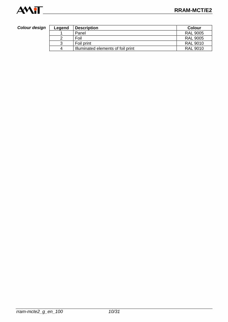
Legend Description Colour
1 Panel RAL 9005
2 Foil RAL 9005
3 Foil print RAL 9010
4 Illuminated elements of foil print RAL 9010
Colour design

RRAM-MCT/E2
11/31 rram-mcte2_g_en_100
2.3. Recommended drawing symbol
Following drawing symbol is recommended for RRAM-MCT/E2.
RRAM-MCT/E2
X3
ETHM12
X4
UIC7
UIC6
UIC5
UIC4
5
6
7
3
4
8 UIC8
X2
UIC3
UIC2
UIC11
2
GND
PE1
2
X1
SPKA+
SPKA-
SPKB-
SPKB+
Vcc
5
6
7
3
4
9
10
8
GND-RS
B
A
ETHM12
X5
LINE INJack 3,5mm
Obr. 3 - Recommended drawing symbol for RRAM-MCT/E2
RRAM-MCT/E2
rram-mcte2_g_en_100 12/31
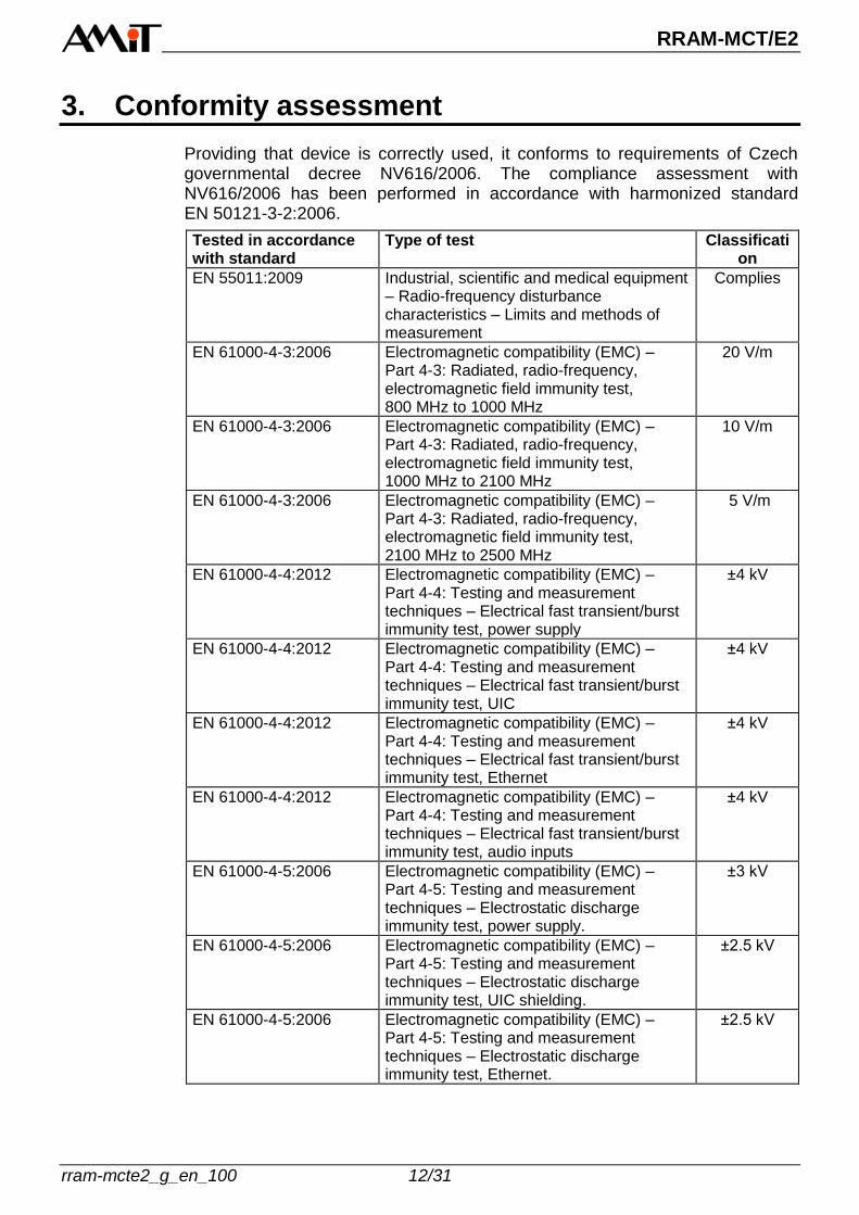
3. Conformity assessment
Providing that device is correctly used, it conforms to requirements of Czech governmental decree NV616/2006. The compliance assessment with NV616/2006 has been performed in accordance with harmonized standard EN 50121-3-2:2006.
Tested in accordance with standard
Type of test Classification
EN 55011:2009 Industrial, scientific and medical equipment – Radio-frequency disturbance characteristics – Limits and methods of measurement
Complies
EN 61000-4-3:2006 Electromagnetic compatibility (EMC) – Part 4-3: Radiated, radio-frequency, electromagnetic field immunity test, 800 MHz to 1000 MHz
20 V/m
EN 61000-4-3:2006 Electromagnetic compatibility (EMC) – Part 4-3: Radiated, radio-frequency, electromagnetic field immunity test, 1000 MHz to 2100 MHz
10 V/m
EN 61000-4-3:2006 Electromagnetic compatibility (EMC) – Part 4-3: Radiated, radio-frequency, electromagnetic field immunity test, 2100 MHz to 2500 MHz
5 V/m
EN 61000-4-4:2012 Electromagnetic compatibility (EMC) – Part 4-4: Testing and measurement techniques – Electrical fast transient/burst immunity test, power supply
±4 kV
EN 61000-4-4:2012 Electromagnetic compatibility (EMC) – Part 4-4: Testing and measurement techniques – Electrical fast transient/burst immunity test, UIC
±4 kV
EN 61000-4-4:2012 Electromagnetic compatibility (EMC) – Part 4-4: Testing and measurement techniques – Electrical fast transient/burst immunity test, Ethernet
±4 kV
EN 61000-4-4:2012 Electromagnetic compatibility (EMC) – Part 4-4: Testing and measurement techniques – Electrical fast transient/burst immunity test, audio inputs
±4 kV
EN 61000-4-5:2006 Electromagnetic compatibility (EMC) – Part 4-5: Testing and measurement techniques – Electrostatic discharge immunity test, power supply.
±3 kV
EN 61000-4-5:2006 Electromagnetic compatibility (EMC) – Part 4-5: Testing and measurement techniques – Electrostatic discharge immunity test, UIC shielding.
±2.5 kV
EN 61000-4-5:2006 Electromagnetic compatibility (EMC) – Part 4-5: Testing and measurement techniques – Electrostatic discharge immunity test, Ethernet.
±2.5 kV
RRAM-MCT/E2
13/31 rram-mcte2_g_en_100
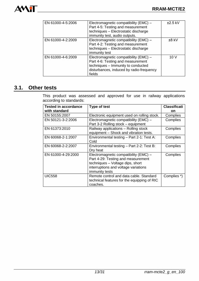
EN 61000-4-5:2006 Electromagnetic compatibility (EMC) – Part 4-5: Testing and measurement techniques – Electrostatic discharge immunity test, audio outputs.
±2.5 kV
EN 61000-4-2:2009 Electromagnetic compatibility (EMC) – Part 4-2: Testing and measurement techniques – Electrostatic discharge immunity test
±8 kV
EN 61000-4-6:2009 Electromagnetic compatibility (EMC) – Part 4-6: Testing and measurement techniques – Immunity to conducted disturbances, induced by radio-frequency fields
10 V
3.1. Other tests
This product was assessed and approved for use in railway applications according to standards:
Tested in accordance with standard
Type of test Classification
EN 50155:2007 Electronic equipment used on rolling stock. Complies
EN 50121-3-2:2006 Electromagnetic compatibility (EMC) – Part 3-2 Rolling stock – equipment
Complies
EN 61373:2010 Railway applications – Rolling stock equipment – Shock and vibration tests.
Complies
EN 60068-2-1:2007 Environmental testing – Part 2-1: Test A: Cold
Complies
EN 60068-2-2:2007 Environmental testing – Part 2-2: Test B: Dry heat
Complies
EN 61000-4-29:2000 Electromagnetic compatibility (EMC) – Part 4-29: Testing and measurement techniques – Voltage dips, short interruptions and voltage variations immunity tests
Complies
UIC558 Remote control and data cable. Standard technical features for the equipping of RIC coaches.
Complies *)

RRAM-MCT/E2
rram-mcte2_g_en_100 14/31
4. Power supply
The RRAM-MCT/E2 unit can be powered only by DC power supply +24 V. Power supply conductors cross-section must be at least 0,5 mm2.
X1
Obr. 4 - Location of X1 connector with power supply pins
The PE terminal is internally connected with exchange cover and panel as well as with metal caps of all connectors. Connector type: WAGO 769-670
Connector Pin Signal Meaning
X1 1 PE Unit chassis
2 GND Power supply, ground
3 Vcc Power supply, +24 V DC
4 SPK B+ B channel output +
5 SPK B- B channel output -
6 SPK A- A channel output -
7 SPK A+ A channel output +
8 A RS485 interface, A line
9 B RS485 interface, B line
10 GND-RS RS485 line, ground
Connecting to CHS
Connector wiring
RRAM-MCT/E2
15/31 rram-mcte2_g_en_100
5. Communication lines
The train phone exchange RRAM-MCT/E2 has following communication interfaces: 1 × RS485 2 × Ethernet
5.1. RS485
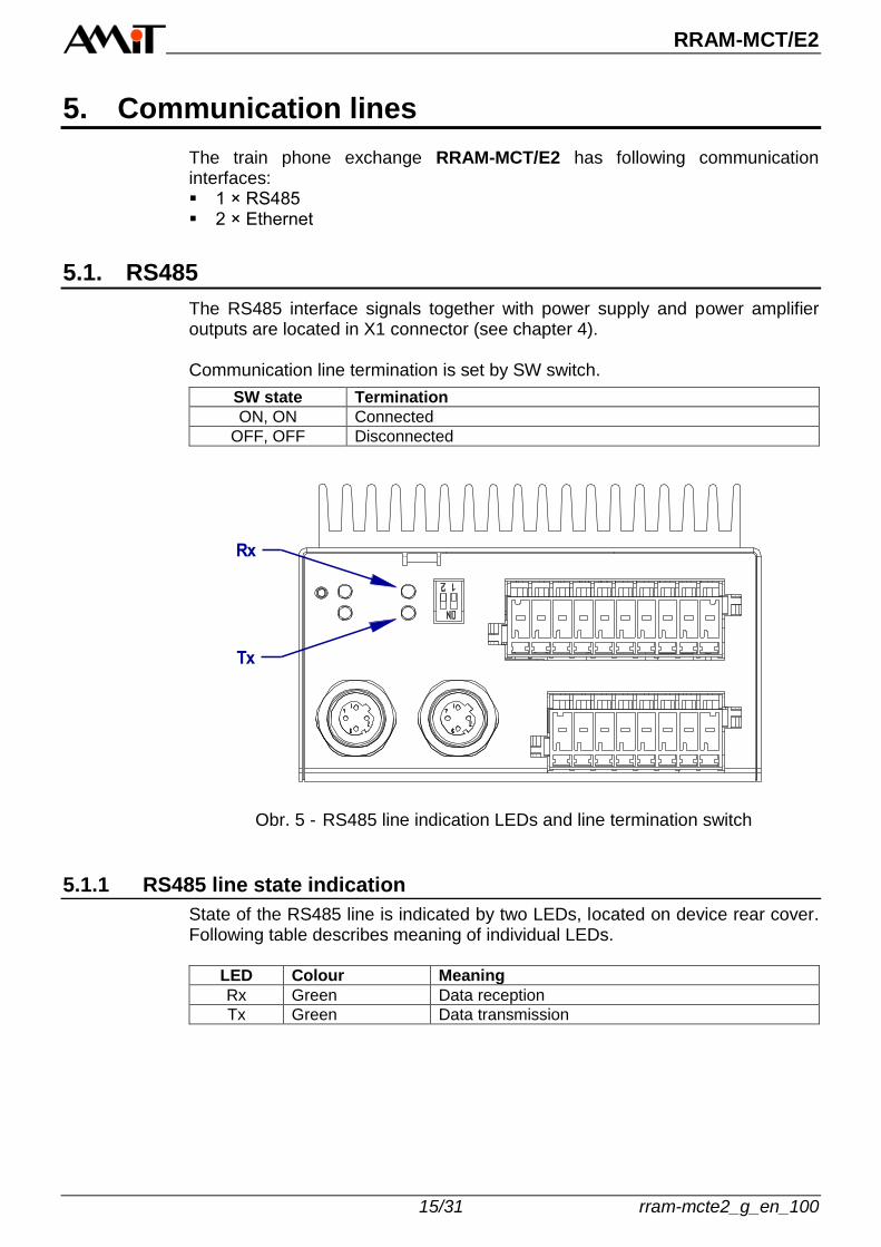
The RS485 interface signals together with power supply and power amplifier outputs are located in X1 connector (see chapter 4). Communication line termination is set by SW switch.
SW state Termination
ON, ON Connected
OFF, OFF Disconnected
Rx
Tx
Obr. 5 - RS485 line indication LEDs and line termination switch
5.1.1 RS485 line state indication
State of the RS485 line is indicated by two LEDs, located on device rear cover. Following table describes meaning of individual LEDs.
LED Colour Meaning
Rx Green Data reception
Tx Green Data transmission

RRAM-MCT/E2
rram-mcte2_g_en_100 16/31
5.2. Ethernet
Both Ethernet interfaces enable to communicate with 100 Mbps rate. Both connectors are located on device rear cover.
ACT X3
ACT X4
X3 X4
Obr. 6 - Location of Ethernet connectors and their respective LED indicators
Connector type: M12, D-coding, socket
Connector Pin Signal Meaning
X3, X4 1 TX+ Positive line conductor for data transmis-sion
2 RX+ Positive line conductor for data reception
3 TX- Negative line conductor for data transmis-sion
4 RX- Negative line conductor for data reception
5 SHLD Cable shielding
1
4
3
2
4
1
3
2
5
Obr. 7 - Wiring of M12 Ethernet connector, front view
Connectors wiring
RRAM-MCT/E2
17/31 rram-mcte2_g_en_100
5.2.1 Ethernet line state indication
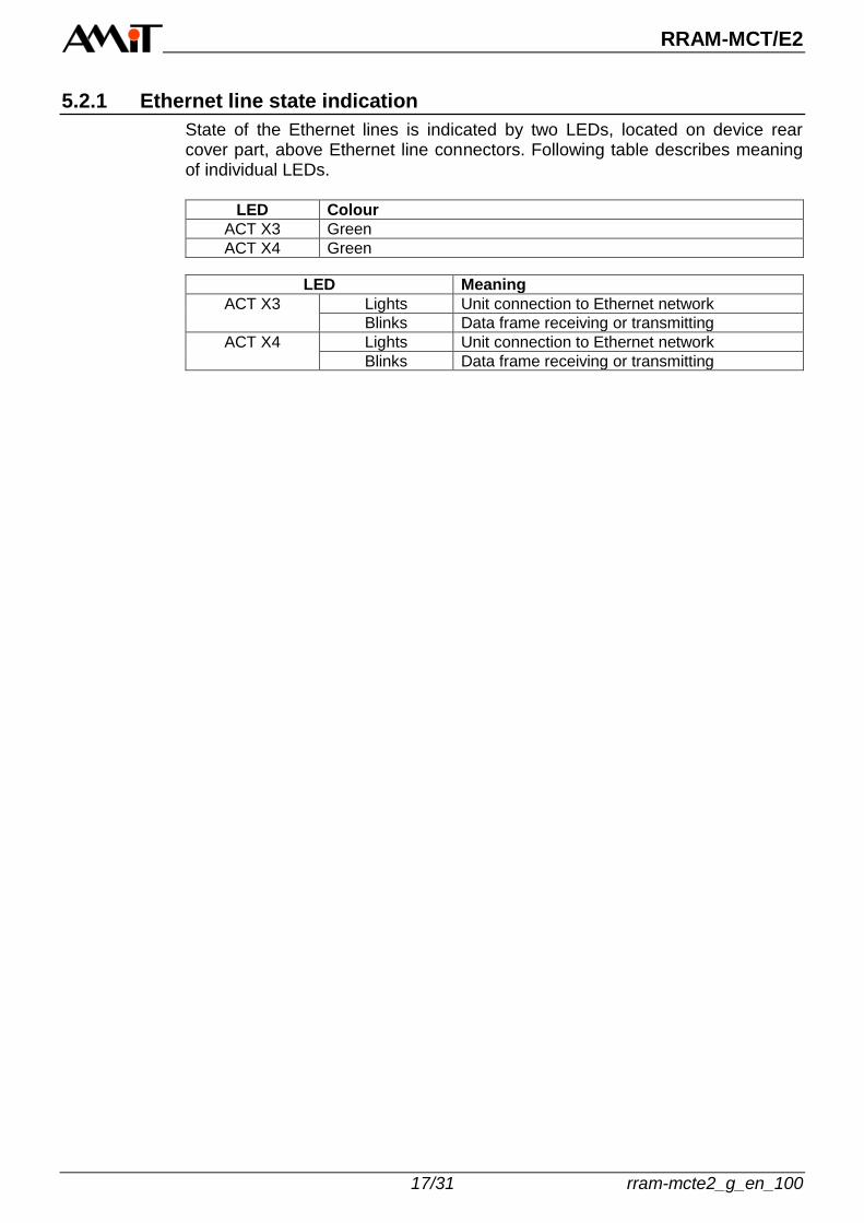
State of the Ethernet lines is indicated by two LEDs, located on device rear cover part, above Ethernet line connectors. Following table describes meaning of individual LEDs.
LED Colour
ACT X3 Green
ACT X4 Green
LED Meaning
ACT X3 Lights Unit connection to Ethernet network
Blinks Data frame receiving or transmitting
ACT X4 Lights Unit connection to Ethernet network
Blinks Data frame receiving or transmitting

RRAM-MCT/E2
rram-mcte2_g_en_100 18/31
6. UIC interface
Unit is equipped with UIC interface according to UIC558 and UIC568 standards. From all functionalities is implemented announcement and telephony.
X2
Obr. 8 - Location of connector X2 with UIC interface
Connector type: WAGO 769-668
Connector Pin Signal Meaning
X2 1 UIC1 Announcement audio signal +
2 UIC2 Announcement audio signal -
3 UIC3 Phone line +
4 UIC4 Phone line -
5 UIC5 Program announcement indication +
6 UIC6 Program announcement indication -
7 UIC7 Priority announcement indication +
8 UIC8 Priority announcement indication -
Connector wiring

RRAM-MCT/E2
19/31 rram-mcte2_g_en_100
6.1.1 UIC line state indication
State of UIC line is indicated by three LEDs on front panel. Following table describes meaning of individual LEDs.
LED Colour Meaning
AOC Yellow Priority announcement is going on
TOC Yellow Phone call is going on
POC Yellow Program announcement is going on
AOC
TOC
POC
Obr. 9 - UIC line state indication
RRAM-MCT/E2
rram-mcte2_g_en_100 20/31
7. Inputs/outputs
7.1. Audio input
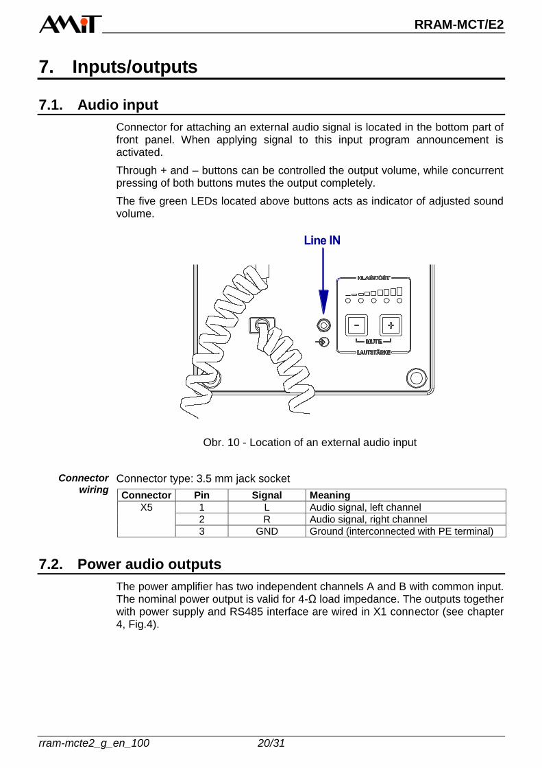
Connector for attaching an external audio signal is located in the bottom part of front panel. When applying signal to this input program announcement is activated.
Through + and – buttons can be controlled the output volume, while concurrent pressing of both buttons mutes the output completely.
The five green LEDs located above buttons acts as indicator of adjusted sound volume.
Line IN
Obr. 10 - Location of an external audio input
Connector type: 3.5 mm jack socket
Connector Pin Signal Meaning
X5 1 L Audio signal, left channel
2 R Audio signal, right channel
3 GND Ground (interconnected with PE terminal)
7.2. Power audio outputs
The power amplifier has two independent channels A and B with common input. The nominal power output is valid for 4-Ω load impedance. The outputs together with power supply and RS485 interface are wired in X1 connector (see chapter 4, Fig.4).
Connector wiring
RRAM-MCT/E2
21/31 rram-mcte2_g_en_100
7.2.1 Rules for connecting loudspeakers
The amplifier outputs can be connected to a different number of loudspeakers.
Rules for connecting: Ensure the total minimum impedance 4 Ω for each channel by combination
of serial and parallel wiring of loudspeakers. Overall power of combination of speakers must be equal or greater than
amplifier maximum output power. When needed, whichever loudspeaker from combination can be substituted
by resistor with the same impedance (resistance) and wattage. Keep the loudspeaker polarity (to avoid playing in the antiphase).
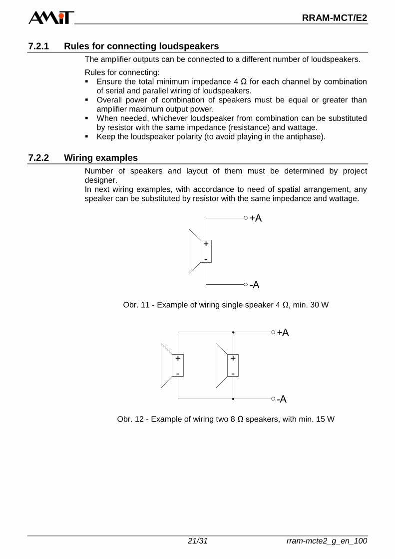
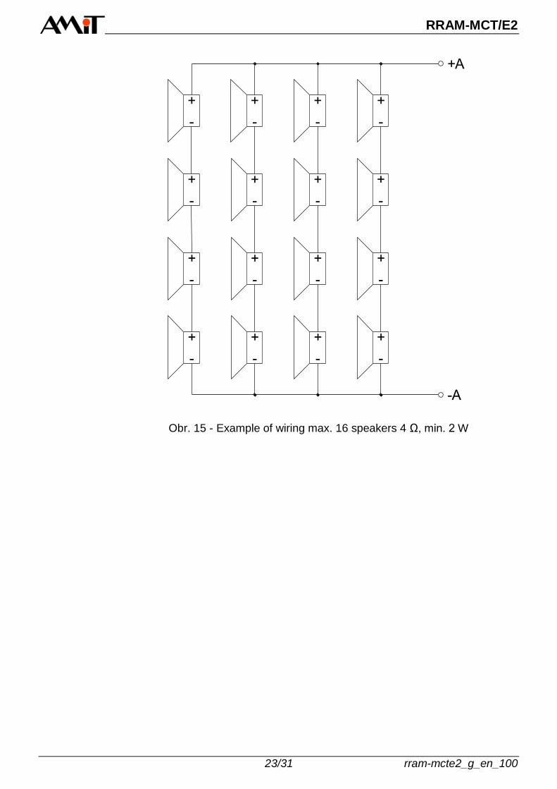
7.2.2 Wiring examples
Number of speakers and layout of them must be determined by project designer. In next wiring examples, with accordance to need of spatial arrangement, any speaker can be substituted by resistor with the same impedance and wattage.
+
-
+A
-A
Obr. 11 - Example of wiring single speaker 4 Ω, min. 30 W
+
-
+
-
+A
-A
Obr. 12 - Example of wiring two 8 Ω speakers, with min. 15 W

RRAM-MCT/E2
rram-mcte2_g_en_100 22/31
+
-
+
-
+
-
+A
-A
+
-
Obr. 13 - Example of wiring four 4 Ω speakers, with min. 8 W
+
-
+
-
+
-
+
-
+
-
+
-
+
-
+A
-A
+
-
Obr. 14 - Example of wiring max. 8 speakers 8 Ω, min. 4 W
RRAM-MCT/E2
23/31 rram-mcte2_g_en_100
+
-
+
-
+
-
+
-
+
-
+
-
+
-
+A
+
-
+
-
+
-
+
-
+
-
+
-
+
-
+
-
-A
+
-
Obr. 15 - Example of wiring max. 16 speakers 4 Ω, min. 2 W

RRAM-MCT/E2
rram-mcte2_g_en_100 24/31
8. Indications and settings
8.1. System LEDs
State of exchange unit is indicated by 2 LEDs on front panel.
PON
ERR
Obr. 16 - System LEDs on front panel
Following table describes meaning of individual LEDs.
LED Colour
PON Green
ERR Red
Status Meaning
PON LED ERR LED
Lights Does not light Operation status
Lights Lights Amplifier overload
Blinks regularly Lights Improper unit configuration
Blinks irregularly Lights Application start failed
Application program is loaded, device works faultless. If too low impedance is attached to the amplifier output, amplifier is overheated or damaged.
Configuration applied in unit is not valid. Use the RRAS configurator for failure removal.
Start of an application failed. To remove the failure is necessary to reload application through RRAS configurator.
Operation status
Amplifier overload
Improper unit configuration
Application start failed

RRAM-MCT/E2
25/31 rram-mcte2_g_en_100
8.2. Factory setting
Factory setting can be restored through RESTORE button. To press the button use a tool with diameter max. 1.5 mm (e.g. match, or ballpoint refill). To restore the factory setting press and hold the RESTORE button while unit start-up. The PON LED first lights ON and after about 5 sec starts to blink. Release the button after beginning of PON LED blinking.
After restoring of factory setting unit goes to operation and the PON LED starts to light permanently. Unit factory setting
Parameter Default value
IP address 192.168.1.1
Network mask 255.255.255.0
Default gateway 0.0.0.0
RESTORE
Obr. 17 - The RESTORE button
Factory setting
RRAM-MCT/E2
rram-mcte2_g_en_100 26/31
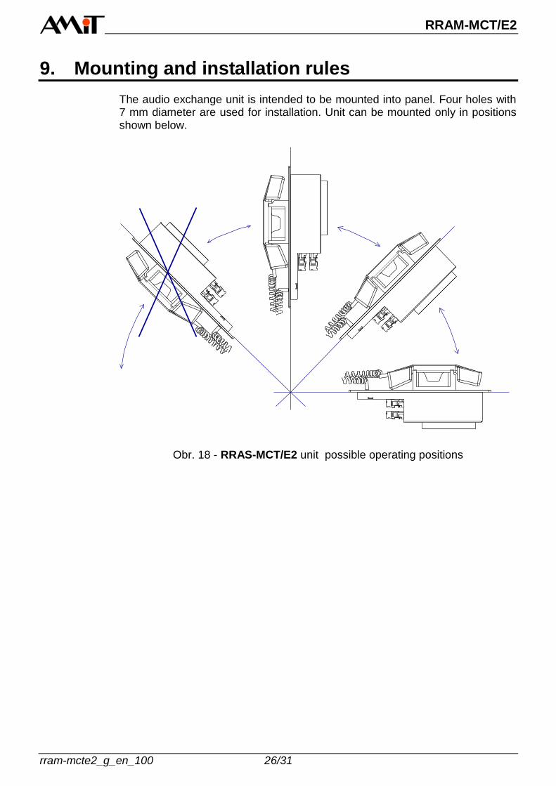
9. Mounting and installation rules
The audio exchange unit is intended to be mounted into panel. Four holes with 7 mm diameter are used for installation. Unit can be mounted only in positions shown below.
Obr. 18 - RRAS-MCT/E2 unit possible operating positions

RRAM-MCT/E2
27/31 rram-mcte2_g_en_100
9.1. Mounting holes
120 mm
118 mm
296 m
m
310 m
m
1 mm
7 m
m
4 x
D 7
mm
Obr. 19 - Mounting holes
RRAM-MCT/E2
rram-mcte2_g_en_100 28/31
5,0 mm
D 1
1,0
mm
D 7
,0 m
m
2,5 mm
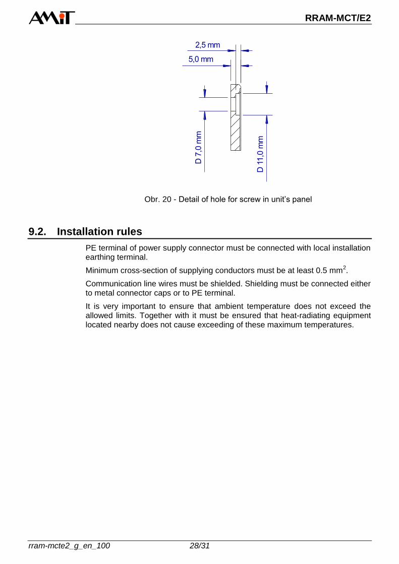
Obr. 20 - Detail of hole for screw in unit’s panel
9.2. Installation rules
PE terminal of power supply connector must be connected with local installation earthing terminal.
Minimum cross-section of supplying conductors must be at least 0.5 mm2.
Communication line wires must be shielded. Shielding must be connected either to metal connector caps or to PE terminal.
It is very important to ensure that ambient temperature does not exceed the allowed limits. Together with it must be ensured that heat-radiating equipment located nearby does not cause exceeding of these maximum temperatures.
RRAM-MCT/E2
29/31 rram-mcte2_g_en_100
10. Ordering information and completion
RRAM-MCT/E2 Unit complete – see chapter 10.1.
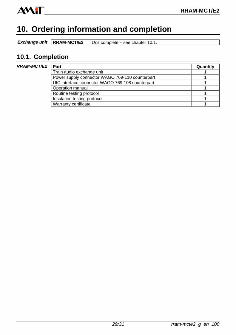
10.1. Completion
Part Quantity
Train audio exchange unit 1
Power supply connector WAGO 769-110 counterpart 1
UIC interface connector WAGO 769-108 counterpart 1
Operation manual 1
Routine testing protocol 1
Insulation testing protocol 1
Warranty certificate 1
Exchange unit
RRAM-MCT/E2

RRAM-MCT/E2
rram-mcte2_g_en_100 30/31
11. Maintenance
Device requires no periodic control nor maintenance. Depending on equipment usage, the dust is to be removed occasionally from equipment. The equipment can be cleaned by dry soft brush or vacuum cleaner, only when turned-off and disassembled. The maintenance mentioned above can be performed by manufacturer or authorized service only!
Cleaning
Note:
RRAM-MCT/E2
31/31 rram-mcte2_g_en_100
12. Waste disposal
The disposal of electronic equipment is subject to the regulations on handling electrical waste. The equipment must not be disposed of in common public waste. It must be delivered to places specified for that purpose and recycled.
Electronics disposal