rracto- technik - orfeus project a new trenchless look ahead radar for mounting an horizontal...
TRANSCRIPT

Developing a new trenchless Lookahead radar for mounting an
Horizontal Drilling Equipment
OSYStechnology limited
IDSINGEGNERIA DEI SISTEM I--i%0
cri Gaz de France
rRACTO-", TECHNIK
TuDelftDelft University of Technolog y
BRNOUNIVERSITYOF TECHNOLOGY
i I
Dipl.-Ing. Elmar Koch
Head of Design Department
Tracto-Technik GmbH & Co. KG CFIC

Who is Tracto-Technik
1962 Founding of TRACTO-TECHNI K
The Iittle workshop . . .
lt all started in a Iittle workshop for rent in Saalhausen .
Company founder Paul Schmidt

Who is Tracto-Technik
1970 The first German soil dispiacement hammer
The first generation of Grundomat hammers The Grundomat hammer today
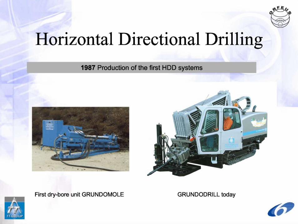
Horizontal Directional Drilling1987 Production of the first HDD systems
First dry-bore unit GRUNDOMOLE GRUNDODRILL today

TTTechnologies
(USA)
TT international
TT U K(England)
TRACTO-TECHNI K(Germany)
TRACTO-TECHNIQUES (France)
TT Asia-Pacifi c
(Australia)

What is HDD
• Horizontal Directional Drilling
• Trenchless Installation of pipes and Gables in th eground
• Useable for all kind of ground condition s
• Used for approx . 15% of new installed UndergroundInfrastructure in Germany
• Dimensions from 50 up to 800 mm

Pilot bore
Expander with attached pipe
Method of HHD drilling

Mini Drill Rig - GRLTNDOPIT
GRUNDOPIT in transport position .
The Compact dimensions enable starting fromthe smallest of pits and shafts .

Grundodrill 25N

.
.
.
HDD vs . open Trenching
Required construction time 2 .5 to 3 times shorterLess affected traffic areasNoise and dust factor at least 10 : 1
• Required amount of reinstatement material (1/100)• Reducing the indirect costs, caused by :
— Traffic disturbance
— Damage to Hora and faun a
— Health cost
— Road surface costs— Repair cost

What to do before drilling
• Check the infrastructure inthe ground
• Study plans of all networkowners
• Use surface informationlike fireplugs and housevalves
• Re-check these informatio nabout the buried objects byusing a location system anthe jobsite
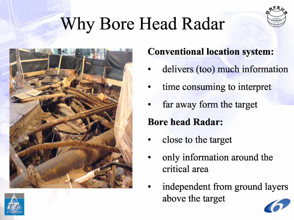
Why Bore Head Radar
Conventional location System :
• delivers (too) much information
• time consuming to Interpre t
• far away form the target
Bore head Radar :
• close to the target
• only information around thecritical area
• independent from ground layer sabove the target

HDD and Radar
• A radar system mounted on the bore-head of the HDD systemcould be a method of further reducing the risk of damage toadjacent plant during operations
. Because the radar will be as close as possible to the drilling head ,the probability of obtaining a warning of objects that could bedamaged, or deflecting the path of the drill string, is maximised
• The bore-head radar should have the capability to look in theforward and sideways directions
• Information from the radar have to be passed to the operator onthe surface so that objects that would otherwise be struck may besteered around and thus avoided
we,

System architectureTX and RX antenna hosted in the drilling head to look-ahead
. TX and RX antenna hosted in the drill rod to provide the sidelooking capability
• multi-channel timing circuit for controlling both the antennas
• an A/D conversion board and the interface to the contro lcomputer
• the Power supply module
POWER l~rlL -
y r, 'r 1 tia .

The Bore Head GPR
Therefore, main design tasks are related to :
• The provision of durable antennas and "look-ahead" an d"look-sideways" capabilitie s
• The design of ruggedized microwave sources andreceivers
.
The development of new concents for si2nal and dataprocessing algorithms

Drilling with bore head radar

Drilling with bore head radar

Drilling with bore head radar

Drilling with bore head radar

Drilling with bore head radar

Drilling with bore head radar

The end-user requirement s
A comprehensive (and demanding!) set ofrequirements has been developed by the end-userincluding the requested—detection distance (50 cm — 100 cm)—minimum detectable object size (10 mm)—Resolution (300 mm)—axial and radial accuracy (10% of the range )—target detection percentage (>95%)—false target generation percentage (< 1 %)—Form of the display

Data processingThe form of the display is different from those that have bee ndeveloped for interpreting data collected by GPR operating fro mthe surface
• A test site was implemented and used to collect some preliminarydata sets
axis of rotation
äL '

Data processing
Ech.c -.'=
P :PP-
UM 3 Zl 5 • 2i „7 15 : :3 .YJ C.u.en xw5 43. r1A
mir ~
AMEN—

Artificial Test Chamber
drill rig wit hdrive unit an ddocking station
Test stand box
filled-up with sol llength = 6000m mbreadth =3000m mdepth =3000mm
Power Supply

Artificial Test Chamber

Information sources
•www.orfeus-project .eu
• Periodic User Workshop s
• Join the Mailing list

Any Questions ???

Acknowledgment
The ORFEUS project is partly supported by th eEuropean Commission's 6th Framework Programfor Community Research ("Thematic Priority"area of sustainable development, global chang eand ecosystems), managed by Directorate Genera lfor Research under the contract n° FP6-2005 -Global-4-036856 and would not haue beenpossible without the support of the Commission