rr959 - application of a testing regime for offshore fire ... · health and safety executive...
TRANSCRIPT
Health and Safety Executive
Application of a testing regime for offshore fire dampers
Prepared by the Health and Safety Laboratory for the Health and Safety Executive 2013
RR959 Research Report

Health and Safety Executive
Application of a testing regime for offshore fire dampers
S F Jagger Harpur Hill Buxton Derbyshire SK17 9JN
Fire dampers are used widely offshore as components of heating and ventilation systems yet the testing regime in place is inappropriate for offshore, where the possibility of hydrocarbon releases leading to a jet fire is high. This is because it simply uses an oven and therefore does not simulate the forces that a jet fire or explosion would exert on what is a precision piece of engineering equipment.
In this report HSL have developed and proposed a new test and demonstrated its practicablity.
To do this a standard H60 fire damper purchased from a UK manufacturer and subject to the test procedure set out in ISO TS27469, exposing it to a vapour cloud blast with an overpressure of ~0.40 bar and a jet fire test according to ISO 22899-1.
Under test conditions the Fire Dampers (as supplied) failed when subject to jet flame impingement after exposure to a defined explosion over pressure and were therefore deemed to not meet the performance requirements expected for a jet fire rated blast wall in which they may be located. As a result it can be concluded that the presence of such dampers in a performance certified blast/fire wall would negate the rating of the wall.
This report and the work it describes were funded by the Health and Safety Executive (HSE). Its contents, including any opinions and/or conclusions expressed, are those of the author alone and do not necessarily reflect HSE policy.
HSE Books

© Crown copyright 2013
First published 2013
You may reuse this information (not including logos) free of charge in any format or medium, under the terms of the Open Government Licence. To view the licence visit www.nationalarchives.gov.uk/doc/open-government-licence/, write to the Information Policy Team, The National Archives, Kew, London TW9 4DU, or email [email protected].
Some images and illustrations may not be owned by the Crown so cannot be reproduced without permission of the copyright owner. Enquiries should be sent to [email protected].
ACKNOWLEDGEMENTS
The assistance of the following is gratefully acknowledged:
n Jim Fletcher for conducting the vapour explosion test. n HSL Workshops staff for converting the ISO Container and
mounting the damper within it. n Stewart Buckingham for his general assistance. n Gordon Swinton for his wide ranging knowledge of dampers. n Martin Brearley for encouragement and discussions.
ii

EXECUTIVE SUMMARY
Fire dampers are used widely offshore as components of heating and ventilation systems yet the testing regime in place is inappropriate where the possibility of hydrocarbon releases leading to a jet fire is high.
This work considers this situation and, in particular, seeks to apply a new standard testing protocol in the context of:
• Demonstrating the practicality of the tests detailed in the document;
• exploring and highlighting problems with the procedures making recommendations for improving the test; and
• demonstrating, if possible, that a typical offshore fire damper can attain a measurable level of satisfactory performance.
To do this a standard H60 fire damper with a blade leakage of 0.007 m3s-1m-2 @ 2000 Pa was specified and purchased from a UK manufacturer and subject to the test procedure set out in ISO TS27469, exposing it to a vapour cloud blast with an overpressure of ~0.40 bar and a jet fire test according to ISO 22899-1.
The damper appeared to withstand the blast test but was penetrated by the jet flame after 9-10 s. It thus appeared unsuitable to form any part of a fire resistant barrier if used alone. It is unlikely to provide the necessary fire resistance. Consideration should be given to the use of a zero leakage barrier with an H120 fire damper which might be termed a Ventilation Penetration Protection System (VPPS).
The use of any product/system that allows any gas into a duct where it could possibly ignite is not acceptable in a Temporary Safe Refuge (TSR).
The test procedure appeared fit-for-purpose except for a small number of minor modifications/suggestions.
iii

iv

CONTENTS PAGE
1. INTRODUCTION ........................................................................ 1 1.1 General 1 1.2 Standards Regime 1 1.3 This Work 2
2. EXPERIMENTAL ....................................................................... 4 2.1 The Damper 4 2.2 The Blast Explosion Test 4 2.3 The Jet Fire Test 16
3. DISCUSSION ........................................................................... 25 3.1 This Damper 25 3.2 The Test Procedure 25
4. REFERENCES ......................................................................... 26
v

vi

1. INTRODUCTION
1.1 GENERAL
Dampers of various types are commonly found as integral components in heating, ventilation and air conditioning (HVAC) systems. They are generally used to control the circulation in ducted systems but frequently are also required to perform essential safety functions. Thus shutoff or gas dampers are installed to prevent the ingress of noxious gases into a ventilation system. Shut-off dampers may also be termed smoke dampers if they are required to protect against the ingress of smoke. Fire dampers are extensively used offshore and located in fire rated partitions to prevent the spread of flame and must be installed to maintain the integrity of the rated partition. Such dampers, installed in a Temporary Safe Refuge (TSR), are particularly critical in ensuring that, in the event of an incident, the TSR fulfils its function and provides protection for its occupants for the designated time.
There have been concerns recently that dampers installed offshore may not be fit for purpose. Thus White (2003) raised issues regarding validation of their installed performance. He highlighted the fact that there was very little testing of installed dampers carried out. In general operators used Control Room indicators to show that a damper had closed properly but found that this was not always a reliable pointer. Additionally hardly any on-site leakage testing was carried out. White also surveyed damper manufacturers and found concerns regarding the testing and certification regime. He discovered that this was appropriate for on-shore installations but did not address specific off-shore problems. Thus off-shore dampers are installed in large steel bulkheads as opposed to masonry walls and are most likely to be exposed to a hydrocarbon fuelled fire rather than a cellulosic fire, with a more rapid ramp up of temperature and higher final temperatures. There is also the possibility that they be required to protect against a hydrocarbon jet fire – the most extreme fire exposure possible. He suggested that the testing regime for offshore dampers should be examined to ensure that it was fit-forpurpose.
1.2 STANDARDS REGIME
The only specific offshore standard which refers to dampers is BS ISO 15138. It details a number of aspects of damper design but does not consider a testing regime to validate performance. The only reference to testing is BS EN 1363-2 which is a general fire testing document not specific to dampers.
The two main standards for damper testing are BS EN 1366 and BS ISO 10294.
BS EN 1366 consists of several parts for the different elements of a HVAC system – Part 2 deals with fire dampers and Part 10 with smoke control dampers installed in fire separating elements. The procedure requires that the dampers are attached, in normal ductwork, to a furnace and then exposed to a standard temperature-time curve while maintaining a constant differential pressure across the damper. Measurements are then taken during the test to assess integrity, insulation and leakage provided by the damper. The standard refers to other standards for the test conditions, specific measurement details and performance criteria. Thus BS EN 1363-1 indicates how the perimeter integrity and should be measured and how thermocouples should be positioned to measure the insulating properties and Part 2 of that standard allows the possibility of exposing the damper to either a cellulosic or hydrocarbon fire curve.
1

1.3
BS ISO 10294-1 specifies a similar test for fire dampers for air distribution systems. Again the damper is installed in a fire separating element as in practice and then, in the open position, exposed to furnace conditions. Closure of the damper is checked and the damper exposed to a sustained 300 Pa differential pressure, except where higher underpressures are appropriate, for example for a smoke damper. Part 2 of this standard defines acceptable criteria for damper performance and sets out leakage rates, conditions for perimeter integrity and temperature limits for unexposed surfaces.
UL 555 for fire dampers details seven tests for the assessment of damper performance. These include procedures to examine cycling, dynamic closure and more importantly fire and hose stream endurance. These are generally less stringent than the BS EN ISO series. The fire test specifies a furnace temperature-time curve which only reaches temperatures of 927 and 1052°C after 1 and 3 hours respectively. Integrity criteria are met if no visible flaming is observed on the unexposed blade side or there are no visible holes >3/8” in the vertical or 1/32" in the horizontal or 3/4” clearance between parts. There are no insulation requirements. UL555S is a related standard dealing with smoke dampers.
It was thus considered necessary to produce a standard dealing specifically with the hazards encountered offshore. Hence ISO/TS 27469: Petroleum, petrochemical and natural gas industries – Method of test for fire dampers published in 2010. This detailed a method of test for fire dampers which included a furnace test simulating a hydrocarbon pool fire as detailed in BS EN 1363-2, a jet fire test with the heating regime set out in ISO 22899-1 and a blast pressure test. The latter involves maximum overpressures between 0.2 and 0.4 bar with a triangular waveform of 100-300 ms duration. The performance in these tests is evaluated against a number of criteria dealing with integrity and insulation. For satisfaction of the integrity criteria, the damper shall show no evidence of flaming on the exposed face and no penetration of flames or hot gasses through cracks or holes or breeches in joints. The insulation criteria uses the exceedance of (a) critical temperature(s) on the unexposed side of the damper installation. Examples of such temperatures are set out in ISO 13702. For fire barriers the critical temperature is typically a rise of 140°C above ambient. The performance of the damper is then expressed as a fire resistance duration to the level of fire attack – hydrocarbon pool or jet fire. Other methods must be used for gas dampers.
THIS WORK
Giorgi (2007) has demonstrated the practicality of testing typical dampers used onshore to standards appropriate for onshore installations and has shown that damper makers manufacture items capable of meeting those standards. Thus tests were performed to BS EN 1366-2 and BS ISO 10294-1 on a nominally 1250 x 1000 mm damper installed in a 150 mm aerated concrete block wall.
The following describes a similar but preliminary exercise on fire dampers intended for use offshore to the Technical Specification ISO 27469. The type of incident against which the envisaged protection is required comprises a release of a flammable gas or vapour from a high pressure source followed by a remote delayed ignition. The result is a vapour cloud explosion followed by a jet fire. The objectives of this exercise were therefore to:
• Demonstrate the practicality of the tests detailed in the document;
• explore and highlight problems with the procedures, making recommendations for improvement of the test; and
2

• demonstrate if possible that a typical offshore fire damper can attain a measurable level of satisfactory performance.
3

2. EXPERIMENTAL
2.1 THE DAMPER
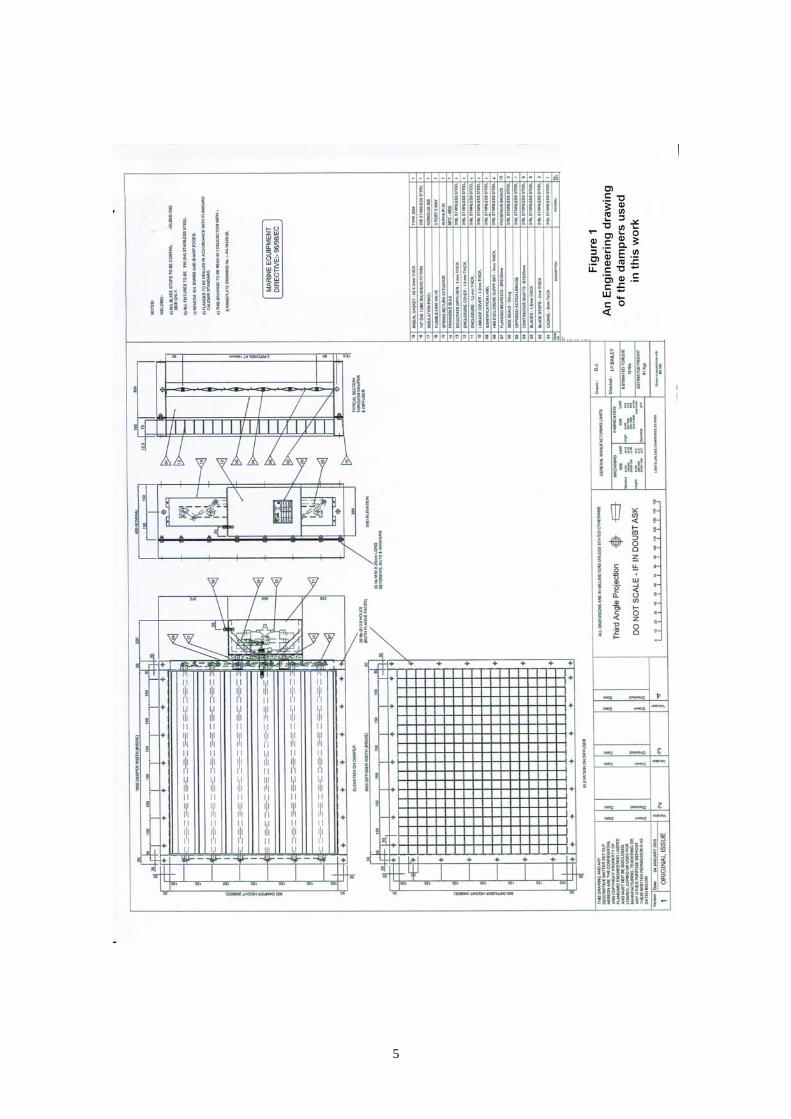
A fire damper was acquired from a well-known UK manufacturer. This was specially prepared for this programme and an engineering drawing is shown in Figure 1. Figure 8a shows the damper as delivered with the internal side upwards. This comprised a horizontal-bladed damper with an opening measuring 1000 mm in the horizontal and 900 mm in the vertical manufactured from 316 stainless steel. When closed the set of six 1.5 mm thick blades interlocked to form a continuous barrier. The damper was opened against a spring by the application of compressed air. There was no fusible link closing mechanism provided.
The damper was mounted within a 300 mm deep stainless steel frame flanged at one end to facilitate mounting. Over the outer face of the damper a diffuser panel was fitted. This comprised a 1000 mm (horizontal) by 900 mm (vertical) internal honeycomb of vertical and horizontal bars giving openings measuring 50 mm square by 75 mm deep. This was intended to deflect the jet flame during the jet fire test. Mounting was facilitated by a 50 mm flange running around the assembly predrilled with 12 mm holes at 150 mm spacing.
2.2 THE BLAST EXPLOSION TEST
2.2.1 General
The purpose of the blast pressure test is to establish the level of overpressure that the damper is capable of withstanding in the closed position without impairment to its fire barrier function. A fire damper’s blast pressure withstand capability should not be confused with the functions necessary to provide blast protection, for which a different type of damper is required.
The technical specification indicates that the pressure load can be tested in steady state or in dynamic conditions resembling a triangular pressure pulse of minimum 300 ms duration as shown in Figure 2. A typical gas explosion pressure wave will have a duration of 100-300 ms. The fire dampers blast pressure rating is the maximum overpressure to which it can be subjected without losing its ability to provide protection as a fire barrier. Dampers can be classified according to the following scheme detailed in ISO/TS 27469:
• Class 1 Blast overpressure class 20 kPa (0.2 bar)
• Class 2 Blast overpressure class 30 kPa (0.3 bar)
• Class 3 Blast overpressure class 40 kPa (0.4 bar)
Figure 2 A typical design explosion pulse of over pressure of ΔP0 and duration T0
ΔP0
T0
4
5
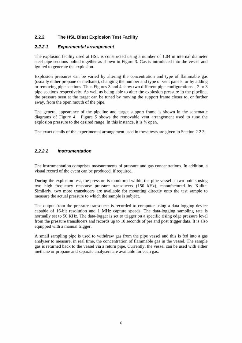
2.2.2 The HSL Blast Explosion Test Facility
2.2.2.1 Experimental arrangement
The explosion facility used at HSL is constructed using a number of 1.04 m internal diameter steel pipe sections bolted together as shown in Figure 3. Gas is introduced into the vessel and ignited to generate the explosion.
Explosion pressures can be varied by altering the concentration and type of flammable gas (usually either propane or methane), changing the number and type of vent panels, or by adding or removing pipe sections. Thus Figures 3 and 4 show two different pipe configurations – 2 or 3 pipe sections respectively. As well as being able to alter the explosion pressure in the pipeline, the pressure seen at the target can be tuned by moving the support frame closer to, or further away, from the open mouth of the pipe.
The general appearance of the pipeline and target support frame is shown in the schematic diagrams of Figure 4. Figure 5 shows the removable vent arrangement used to tune the explosion pressure to the desired range. In this instance, it is ¾ open.
The exact details of the experimental arrangement used in these tests are given in Section 2.2.3.
2.2.2.2 Instrumentation
The instrumentation comprises measurements of pressure and gas concentrations. In addition, a visual record of the event can be produced, if required.
During the explosion test, the pressure is monitored within the pipe vessel at two points using two high frequency response pressure transducers (150 kHz), manufactured by Kulite. Similarly, two more transducers are available for mounting directly onto the test sample to measure the actual pressure to which the sample is subject.
The output from the pressure transducer is recorded to computer using a data-logging device capable of 16-bit resolution and 1 MHz capture speeds. The data-logging sampling rate is normally set to 50 KHz. The data-logger is set to trigger on a specific rising edge pressure level from the pressure transducers and records up to 10 seconds of pre and post trigger data. It is also equipped with a manual trigger.
A small sampling pipe is used to withdraw gas from the pipe vessel and this is fed into a gas analyser to measure, in real time, the concentration of flammable gas in the vessel. The sample gas is returned back to the vessel via a return pipe. Currently, the vessel can be used with either methane or propane and separate analysers are available for each gas.
6

Figure 3: General view of 1.04 m diameter pipe vessel and target support frame (6 m length shown)
Blast propagation
Ignition point
Pressure transducers inserted through sample
Blanking plates
Polythene sheet to retain gas mixture
Concrete pipe supports
Reinforced concrete pad
Sample under test Partial area
vent
Pressure transducer to monitor explosion pressure in pipeline
Sample support frame
Sample under test
Figure 4: Schematic diagrams of blast exposure pipe vessel; a) side view, b) plan view
7

Figure 5: Removable vent panel arrangements (3/4 open)
Table 1: Pressure transducer information
Location Type Range Serial number
Pipe vessel 1 ETS-1A-375M-17BARSG 0 to 17 bar g. 791-3-81
Pipe vessel 2 ETS-1A-375M-17BARSG 0 to 17 bar g. 791-3-82
Sample 1 ETS-1A-375M-7BARSG 0 to 7 bar g. 7308-5-681
Sample 2 ETS-1A-375M-7BARSG 0 to 7 bar g. 7308-5-682
2.2.2.3 Sample support system
This comprises a 1620 x 1710 mm square frame manufactured from 260 x 90 x 35 box section steel. It is positioned vertically, parallel to and facing the open end of the vessel. It is supported by substantial diagonal cross braces to a lower frame which is both weighted and tied into the pipe vessel to prevent relative movement of the two during a test. The sample-pipe distance can be increased from zero in steps of 250 mm. A typical distance is 750 mm.
The dimensions of the frame have been chosen to match the requirements of the jet-fire test for test specimen dimensions.
2.2.2.4 General operating procedure
Prior to the test date:
1. The pipe vessel is prepared to the desired length and the removable vents adjusted as required.
2. The gas required is selected and installed.
8

3. The test specimen is mounted at the required distance.
On the day of the test:
4. The open end of the tube and removable vent panel sections are covered with polythene sheet to retain the gas in the vessel.
5. The ignition system, comprising two 5-grain blackpowder charges with an electric fuse, is mounted in the vessel and armed.
6. The fan is switched on to provide turbulent mixing of the gas in the vessel.
7. The pressure transducers are energised; the computer and data-logging system is switched on and armed.
8. The gas analyser system is started.
9. From a safe distance, the gas flow into the vessel is initiated and concentrations monitored.
10. At the required concentration, the gas is ignited.
11. Trigger the data-logging system manually if the self trigger did not function.
Post test:
12. Site clean up.
13. Sample removal and examination.
14. Data retrieval and examination.
2.2.3 The Fire Damper Test
2.2.3.1 Test preparations
Prior to mounting the test sample in the mount a series of preparatory blasts were carried out to tune the system to provide the correct blast overpressure. These were performed on 1 and 2 March 2012.
These tests used the full 8 m pipe configuration as shown in Figure 4 with an approximate pipe volume of 6.8 m3. Pressure transducers were located as follows;
• at the closed end of the pipe, on its circumference at the mid height near the point of ignition;
• on the pipe circumference, at pipe mid height beneath the centre of the vent; and
• on the pipe axis at the position the test sample would occupy during the real test 750 mm from the open end of the tube. Measurement of the pressure at this location was achieved by flush-mounting the pressure transducer centrally.
During this exercise propane was used as the fuel, with its concentration in air and the vent area of the final vent being varied to fine tune the generated pressure. The first two vents were completely closed. Each test was initiated using an electrically-fired, 5-grain blackpowder fuse.
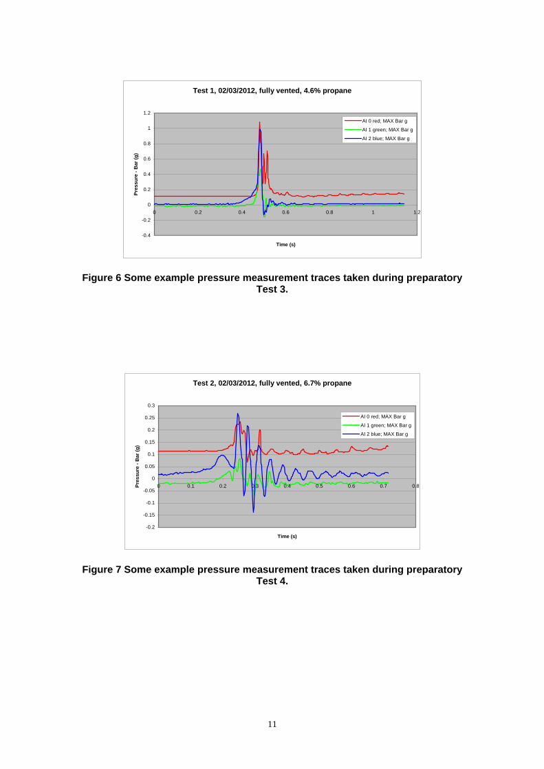
The results for these tests are summarised in Table 2. An example set of pressure traces is given in Figure 6 for Test 4. In the Table the propane concentration quoted is an average of three
9

samples, one taken from each section of the pipe about on the centre plane and on the pipe axis by means of a sampling pump and measured in the Control Cabin using an infra-red gas analyser. Data capture unfortunately failed during the first test.
Table 2 Details of the preparatory test programme
Test Vent Propane Peak over pressures, bar number configuration concentration,
%v/v At ignition Beneath At test point vent sample
position
1 3/4/open 4.1 NA
2 4.5 1.340 0.920 2.170
3 Fully open 4.6 0.982 0.470 1.071
4 6.7 0.267 0.080 0.234
To achieve the target pressure at the test sample of 0.40 bar, the data in Table 2 were examined and extrapolation used to derive the necessary conditions in terms of vent area and propane concentration. Thus from Table 2 it is clear that:
• A fully vented test was required to produce overpressures <1 bar.
• With a full vent opening, the pressure measured near the ignition point closely tracks that at the test sample (to better than 10%) and thus can be used to identify the test exposure where no pressure measurement is carried out at the sample.
• A propane concentration between 4.6 and 6.7% v/v is required. Using a linear extrapolation the required propane test concentration is 6.2 % v/v to produce an overpressure of 0.40 bar.
Figures 6 and 7 show pressure traces from the final two preparatory blast tests. The first of these shows a peak overpressure in excess of 1 bar at the target position (for a concentration of 4.6%) while Test 4 gave a peak pressure of ~0.24 bar for a concentration of 6%. Both these plots indicate that the pressure measured near to the ignition point closely tracks that at the target.
There is some ambiguity in the text of ISO/TS 27469. The type of pressure, reflected or free stream, is not identified. In this case the pressures quoted are reflected and the target pressure sought was assumed to be a reflected pressure. This requires clarification in future revisions of ISO/TS 27469.
10
Test 1, 02/03/2012, fully vented, 4.6% propane
-0.4
-0.2
0
0.2
0.4
0.6
0.8
1
1.2
0 0.2 0.4 0.6 0.8 1 1.2
Time (s)
Pres
sure
- B
ar (g
)
AI 0 red; MAX Bar g
AI 1 green; MAX Bar g
AI 2 blue; MAX Bar g
Figure 6 Some example pressure measurement traces taken during preparatoryTest 3.
Test 2, 02/03/2012, fully vented, 6.7% propane
-0.2
-0.15
-0.1
-0.05
0
0.05
0.1
0.15
0.2
0.25
0.3
0 0.1 0.2 0.3 0.4 0.5 0.6 0.7 0.8
Time (s)
Pres
sure
- B
ar (g
)
AI 0 red; MAX Bar g
AI 1 green; MAX Bar g
AI 2 blue; MAX Bar g
Figure 7 Some example pressure measurement traces taken during preparatory Test 4.
11

Figure 8 A photograph of the fire damper as delivered. The damper is front face down with the actuator mechanism nearest the camera.
2.2.3.2 The Fire Damper Blast Test
For the blast test on the fire damper, the damper was first mounted in the vertical orientation on to a mild steel annulus plate measuring 1620 mm square and 10 mm thick with a cut out 1000 mm square, by bolting through the flange. This in turn was drilled and bolted to the sample holder. The diffuser was front on to the open end of the pipe. This arrangement is shown in Figures 9 and 10 which show the damper and the damper pipe arrangement.
The pipe configuration used was the same as that employed for the preparatory test programme, shown schematically in Figure 4.
Figure 9 The damper mounted ready for the blast test. The diffuser attached to the front of the damper can clearly be seen.
12
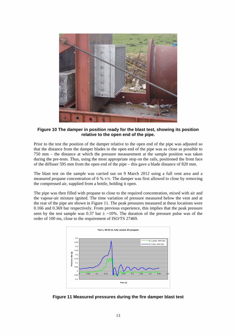
Figure 10 The damper in position ready for the blast test, showing its position relative to the open end of the pipe.
Prior to the test the position of the damper relative to the open end of the pipe was adjusted so that the distance from the damper blades to the open end of the pipe was as close as possible to 750 mm – the distance at which the pressure measurement at the sample position was taken during the pre-tests. Thus, using the most appropriate stop on the rails, positioned the front face of the diffuser 595 mm from the open end of the pipe – this gave a blade distance of 820 mm.
The blast test on the sample was carried out on 9 March 2012 using a full vent area and a measured propane concentration of 6 % v/v. The damper was first allowed to close by removing the compressed air, supplied from a bottle, holding it open.
The pipe was then filled with propane to close to the required concentration, mixed with air and the vapour-air mixture ignited. The time variation of pressure measured below the vent and at the rear of the pipe are shown in Figure 11. The peak pressures measured at these locations were 0.166 and 0.369 bar respectively. From previous experience, this implies that the peak pressure seen by the test sample was 0.37 bar ± ~10%. The duration of the pressure pulse was of the order of 100 ms, close to the requirement of ISO/TS 27469.
Test 1, 09-03-12, fully vented, 6% propane
-0.1
-0.05
0
0.05
0.1
0.15
0.2
0.25
0.3
0.35
0.4
0 0.05 0.1 0.15 0.2 0.25 0.3 0.35 0.4 0.45 0.5
Time (s)
Pres
sure
, Bar
(g)
AI 1 green; MAX Bar
AI 2 blue; MAX Bar
Figure 11 Measured pressures during the fire damper blast test
13
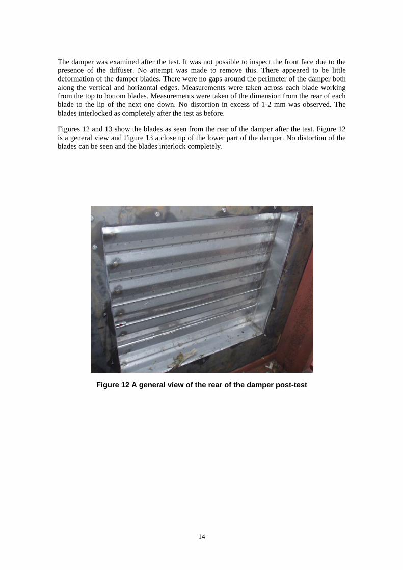
The damper was examined after the test. It was not possible to inspect the front face due to the presence of the diffuser. No attempt was made to remove this. There appeared to be little deformation of the damper blades. There were no gaps around the perimeter of the damper both along the vertical and horizontal edges. Measurements were taken across each blade working from the top to bottom blades. Measurements were taken of the dimension from the rear of each blade to the lip of the next one down. No distortion in excess of 1-2 mm was observed. The blades interlocked as completely after the test as before.
Figures 12 and 13 show the blades as seen from the rear of the damper after the test. Figure 12 is a general view and Figure 13 a close up of the lower part of the damper. No distortion of the blades can be seen and the blades interlock completely.
Figure 12 A general view of the rear of the damper post-test
14

Figure 13 A close-up of the lower rear part of the damper post-test
An opening and closing test was then performed. The air supply to the actuator was cycled several times and the damper opened and closed without delay and without fouling any part of the mechanism on each occasion. Further, during this process, the blades interlocked completely as required. Figure 14 shows a view of the open damper post-test. No distortion of the damper can be seen. Some measurements were taken from the rear of the assembly of the blade positions using the frame as a reference. Measurements of the position at 0.75, 0.50 of the damper height and along the bottom blade showed differences of <1.11 mm in the horizontal and 1.35 mm in the vertical direction. No measurements were taken prior to the test so it is not known if these deviations were as a result of the blast.
Figure 14 A view of the open damper post-test. The damper behaved normally during this test.
15

No leak test was performed on the damper after this test.
2.3 THE JET FIRE TEST
2.3.1 Preparation of the Test Piece
2.3.1.1 Mounting the damper
For the jet fire test, the damper assembly was first installed in the end wall of an ISO container as shown in Figure 15. In reality a standard 20’ container rather than a small one was acquired and used for the test.
Initially a suitably-sized opening was cut in the closed end of the container and a length of ducting inserted into the container. The ducting was manufactured from 6 mm thick stainless steel and measured 900 x 1000 mm in cross section and was 3 m long. It was fitted with two 50 mm stainless steel flanges to each end and was supported inside the container by four legs. The mild steel 12 mm thick plate was bolted to the end wall of the container and the damper and duct flanges offered up the plate, one outside the container and the other inside. Both were bolted through the plate and secured. The diffuser formed the front face of the arrangement and was positioned forward of the container end wall with the damper aligned just forward of the container end wall. Any openings through the container between the in- and out-side were closed by forcing Kaowool mineral fibre insulation into them. Figures 16(a) and 16(b) show front and rear views of the damper installed in the container.
For its first 900 mm inside the container, measured from the front flange, the duct was then encased in 50 mm thick Firebatt mineral wool insulation. This was glued and wired to the ducting and the joints sealed with fireproof filler. This insulation did not extend outside the container as shown in Figure 15 – this area was insulated differently. The insulation as attached to the duct is shown in Figure 17.
Figure 15 The arrangement of the damper/ducting arrangement in the ISO container for the jet fire test.
16

(a) (b)
Figure 16 Front and rear views of the damper installed in the container
Figure 17 A view of the insulation installed at the forward end of the ducting
2.3.1.2 Instrumentation
Prior to transportation to the test site, the ducting was instrumented with seven thermocouples. These were 1.5 mm diameter, stainless steel sheathed, grounded junction K-type sensors. They were connected through to an isothermal box located on the rear right wall (looking inwards) of
17

the container. The thermocouple identifications and their location are summarised in Table 3. Some positions are shown in Figure 15. The data from the thermocouples were recorded at a rate of 1 Hz on a 16-bit data logger.
In addition a further thermocouple was placed at the open end of the duct to detect any flaming at that location and allow shut-off of the test
Table 3 A summary of duct thermocouple locations for the jet fire test
Thermocouple designation
Thermocouple location*
Isothermal box channel
T2022 200 mm on top of duct 1
T2022 200 mm on top of duct 2
T2022 200 mm on top of duct 3
T2022 200 mm on top of duct 4
T2022 200 mm on top of duct 5
T2022 200 mm on top of duct 6
T2022 200 mm on top of duct 7
T2022 200 mm on top of duct 8
* Distances are measured from front flange of duct.
During the test, the damper performance was monitored using a combination of video and close circuit TV (CCTV) cameras. The latter was positioned to view the front of the damper and the jet fire, to the rear left of the jet flame (looking in the direction of the jet) while the former was placed to look up the duct towards the damper from the rear. The CCTV view contained a timer, triggered by operation of the jet.
Additionally a FLIR SC2000 uncooled thermal imaging system was positioned adjacent to the rear video camera looking up the duct to view the rear of the damper louvers. This instrument operates in the 7-13 μm wavelength range producing high resolution imaging at a rate of up to 50 fps recording on an integral PC-based DVD recording system with a 12 bit temperature resolution over a range of –30 to 2000°C. To provide an emissivity reference and allow for emissivity correction of temperatures, half of the rear flange of the ducting was spray painted with a black paint of standard (0-94) emissivity.
2.3.1.3 Installation in the test building
The container/damper arrangement was transported to the test site at Spadeadam, Cumbria on 20/21 March 2012. There, it was installed in GL Noble Denton’s jet fire test building. First it was mounted on blocks to raise it to the correct height relative to the jet and then a coat of fire
18
protection was applied to the front face of the container. This was applied by first fixing a wire mesh to the front of the container and then applying a spray coat of cementicious fire resistant material. This was left to set and cure overnight.
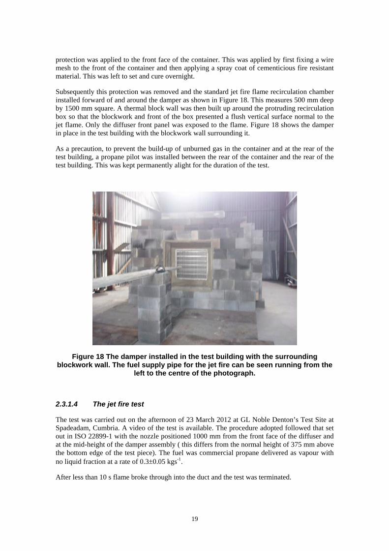
Subsequently this protection was removed and the standard jet fire flame recirculation chamber installed forward of and around the damper as shown in Figure 18. This measures 500 mm deep by 1500 mm square. A thermal block wall was then built up around the protruding recirculation box so that the blockwork and front of the box presented a flush vertical surface normal to the jet flame. Only the diffuser front panel was exposed to the flame. Figure 18 shows the damper in place in the test building with the blockwork wall surrounding it.
As a precaution, to prevent the build-up of unburned gas in the container and at the rear of the test building, a propane pilot was installed between the rear of the container and the rear of the test building. This was kept permanently alight for the duration of the test.
Figure 18 The damper installed in the test building with the surrounding blockwork wall. The fuel supply pipe for the jet fire can be seen running from the
left to the centre of the photograph.
2.3.1.4 The jet fire test
The test was carried out on the afternoon of 23 March 2012 at GL Noble Denton’s Test Site at Spadeadam, Cumbria. A video of the test is available. The procedure adopted followed that set out in ISO 22899-1 with the nozzle positioned 1000 mm from the front face of the diffuser and at the mid-height of the damper assembly ( this differs from the normal height of 375 mm above the bottom edge of the test piece). The fuel was commercial propane delivered as vapour with no liquid fraction at a rate of 0.3±0.05 kgs-1.
After less than 10 s flame broke through into the duct and the test was terminated.
19
2.3.1.5 Test results
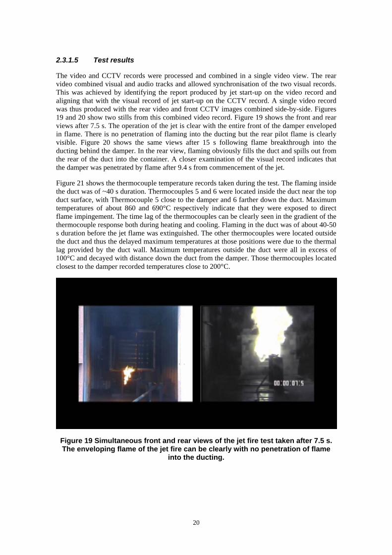
The video and CCTV records were processed and combined in a single video view. The rear video combined visual and audio tracks and allowed synchronisation of the two visual records. This was achieved by identifying the report produced by jet start-up on the video record and aligning that with the visual record of jet start-up on the CCTV record. A single video record was thus produced with the rear video and front CCTV images combined side-by-side. Figures 19 and 20 show two stills from this combined video record. Figure 19 shows the front and rear views after 7.5 s. The operation of the jet is clear with the entire front of the damper enveloped in flame. There is no penetration of flaming into the ducting but the rear pilot flame is clearly visible. Figure 20 shows the same views after 15 s following flame breakthrough into the ducting behind the damper. In the rear view, flaming obviously fills the duct and spills out from the rear of the duct into the container. A closer examination of the visual record indicates that the damper was penetrated by flame after 9.4 s from commencement of the jet.
Figure 21 shows the thermocouple temperature records taken during the test. The flaming inside the duct was of ~40 s duration. Thermocouples 5 and 6 were located inside the duct near the top duct surface, with Thermocouple 5 close to the damper and 6 farther down the duct. Maximum temperatures of about 860 and 690°C respectively indicate that they were exposed to direct flame impingement. The time lag of the thermocouples can be clearly seen in the gradient of the thermocouple response both during heating and cooling. Flaming in the duct was of about 40-50 s duration before the jet flame was extinguished. The other thermocouples were located outside the duct and thus the delayed maximum temperatures at those positions were due to the thermal lag provided by the duct wall. Maximum temperatures outside the duct were all in excess of 100°C and decayed with distance down the duct from the damper. Those thermocouples located closest to the damper recorded temperatures close to 200°C.
Figure 19 Simultaneous front and rear views of the jet fire test taken after 7.5 s. The enveloping flame of the jet fire can be clearly with no penetration of flame
into the ducting.
20
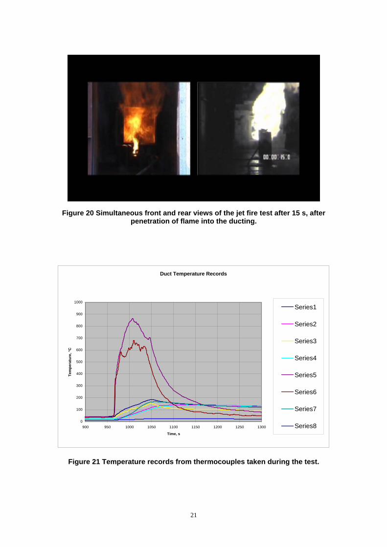
Figure 20 Simultaneous front and rear views of the jet fire test after 15 s, after penetration of flame into the ducting.
Duct Temperature Records
0
100
200
300
400
500
600
700
800
900
1000
900 950 1000 1050 1100 1150 1200 1250 1300
Time, s
Tem
pera
ture
, °C
Series1
Series2
Series3
Series4
Series5
Series6
Series7
Series8
Figure 21 Temperature records from thermocouples taken during the test.
21

2.3.1.6 Dismantling the damper
Following the damper test, the container/damper ducting arrangement was separated from the blockwork wall and recirculation box and transported back to HSL Buxton. There the damper was unbolted from the container and ducting. The lagging around the damper/ducting assembly was inspected and found to be intact, with no penetrations and route for flaming to find its way into the interior of the chamber. The insulation was also found to be intact and undamaged. The damper was then transported to the manufacturer for disassembly and inspection.
At the manufacturer the diffuser was first removed from the front of the assembly. Figure 22 shows a view of the damage to front face of the diffuser. There is clear heat damage to the centre of the diffuser as evidenced by the discolouration. There is also deformation of the front face, probably due to thermal effects with the metal retreating from the flame.
Figure 23 shows the deformation to the frame observed after removal of the diffuser. This deformation was in the horizontal direction and amounted to ~8-10 mm over the damper width. It is likely to have been due to the differential heating produced by the jet flame.
Figure 22 A view of the damper diffuser at the manufacturers prior to dismantling.
22

Figure 23 The deformation to the damper frame observed during dismantling.
Figures 24(a) and 24(b) show close-ups of the damper blades taken during the dismantling process.
(a) (b)
Figure 24 views of the blades taken during damper dismantling.
The first shows the blades in their closed position. Deformation in the blades across the damper can be seen by examining the blade farthest from the camera. The blade appears bowed towards the camera in the centre of the damper. The second shows the blades in the open position. Again deformation of the blade can be seen from the unequal gap between the two lowest dampers –
23

there is no gap in the centre. This deformation is probably due to differential heating produced by the jet flame.
24

3. DISCUSSION
3.1 THIS DAMPER
This fire damper appeared to survive the blast test but failed to prevent the passage of a jet flame when exposed to a standard jet fire. Ignition or ingress of flame occurred in the ducting behind the damper some 9-10 s after exposure to the jet fire. This was probably due to leakage of flame through the damper blades or to penetration of gas through the damper and subsequent autoignition from the hot damper blades. Differential heating of the blades leading to their deformation and the dynamic pressure of the jet forcing gas through any gap created could have led to the necessary leakage through the damper.
It is unlikely that any simple single fire damper system, which is allowed to pass a flow of 0.07 m3s-1m-2 at 2000 Pa, would satisfy any jet fire rating. Should it be required to locate a damper in a J-rated barrier and maintain integrity for a period typically of 1 hour, the only current practical approach is to use a combination of damper types – probably a fire damper together with a nonporous bubble tight barrier and possibly pressure relief damper.
3.2 THE TEST PROCEDURE
One purpose of this work was to develop a procedure for validating damper performance for an offshore environment. There are several potential improvements to the methodology adopted here. This, in turn, has implications for the test standard and suggests a number of modifications to the text:
• Firstly it would be wise to refine the blast test carried out here to ensure it is repeatable and the pressure is more tightly specified. Thus further blast tests should be carried out with improved instrumentation to more closely fix the pressure seen by the damper and examine its variability. It is also not clear in the standard if the pressure levels required are direct or reflected pressures. Should the test be adopted widely then a round-robin comparison between different blast rigs might be advisable to ensure uniformity of test conditions.
• It would be wise to specify that the damper should be leak tested between blast and jet fire tests, preferably by the manufacturer, to provide evidence that the damper had survived the blast test with its performance unaffected.
• During the jet fire test, it is recommended that the damper be mounted in the recirculation box and then in a barrier identical to the one to which it will be coupled in end use – a J-rated bulkhead. This should be combined with ca 225 mm of ceramic insulation around and to the rear of the damper to protect the rear-mounted ducting. This should possibly be substituted for the blockwork wall used in this programme which may have been partly responsible for the deformation to the damper frame.
25

4. REFERENCES
Giorgi R, Fire resistance test in accordance with European Standard EN1366-2:1999 and International standard ISO 10294-1:1996 on an HVC Supplies (Stourbridge) Ltd curtain blade fire damper, BRE Test report 232943, BRE Garston, 2007.
International Standards Organisation, Petroleum, petrochemical and natural gas industries – Method of test for fire dampers, ISO/TS 27469, 2010.
International Standards Organisation, Determination of the resistance to jet fires of passive fire protection materials – Part 1: General requirements, International standards Organisation, 2007.
White G P, HVAC Fire and Smoke Dampers – Phase 1: Literature search and Initial Site Visits, HSL Report IR/ECO/01/12, 2003
Published by the Health and Safety Executive 02/13

Health and Safety Executive
Application of a testing regime for offshore fire dampers
Fire dampers are used widely offshore as components of heating and ventilation systems yet the testing regime in place is inappropriate for offshore, where the possibility of hydrocarbon releases leading to a jet fire is high. This is because it simply uses an oven and therefore does not simulate the forces that a jet fire or explosion would exert on what is a precision piece of engineering equipment.
In this report HSL have developed and proposed a new test and demonstrated its practicablity.
To do this a standard H60 fire damper purchased from a UK manufacturer and subject to the test procedure set out in ISO TS27469, exposing it to a vapour cloud blast with an overpressure of ~0.40 bar and a jet fire test according to ISO 22899-1.
Under test conditions the Fire Dampers (as supplied) failed when subject to jet flame impingement after exposure to a defined explosion over pressure and were therefore deemed to not meet the performance requirements expected for a jet fire rated blast wall in which they may be located. As a result it can be concluded that the presence of such dampers in a performance certified blast/fire wall would negate the rating of the wall.
This report and the work it describes were funded by the Health and Safety Executive (HSE). Its contents, including any opinions and/or conclusions expressed, are those of the author alone and do not necessarily reflect HSE policy.
RR959
www.hse.gov.uk