rptcs - russelectric · 2019-03-03 · • modbus rtu via rs485 (standard) • modbus tcp/ip via...
TRANSCRIPT
800 225-5250 russelectric.com info @ russelectric.com
RPTCS
ATS Control System

6
3
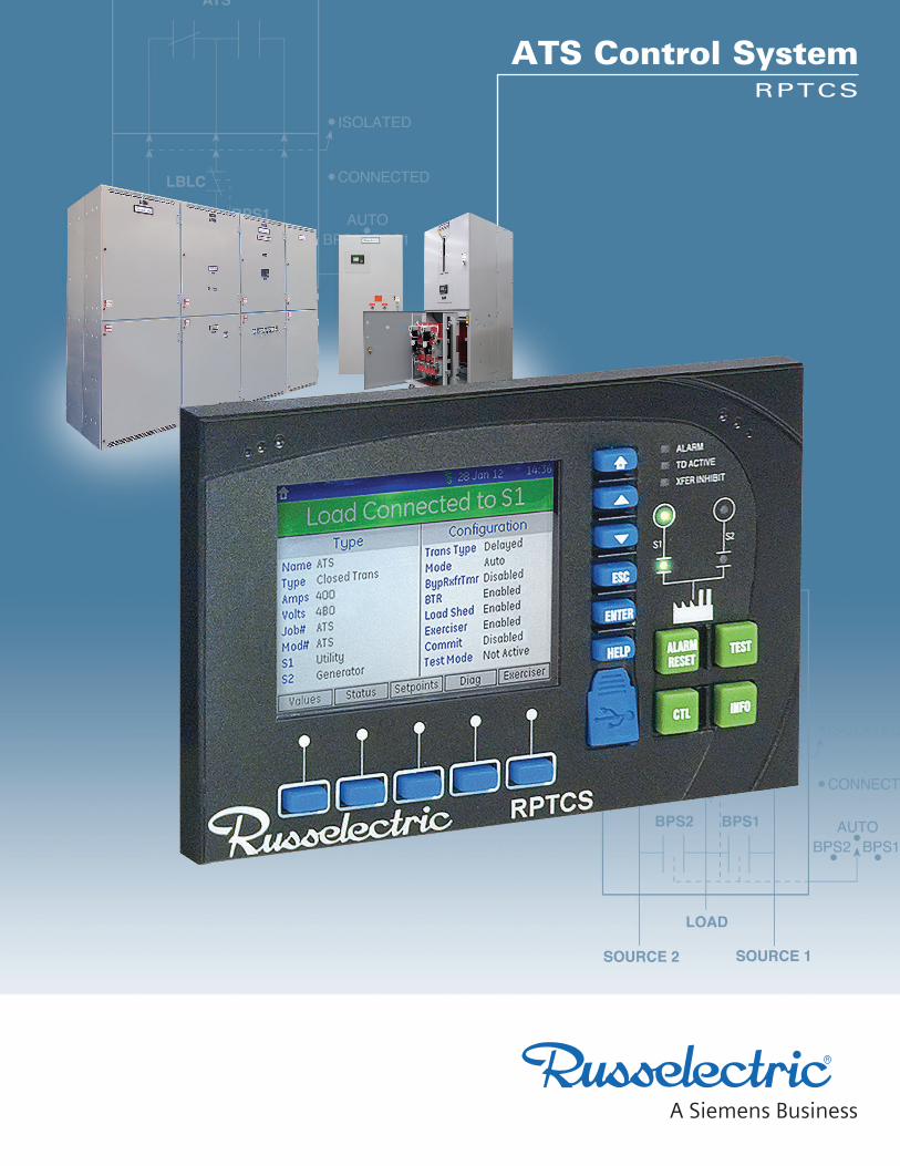
RPTCS Automatic Transfer Switch Control System
2
Control of All Operational Functions Used exclusively on Russelectric RTS Series transfer and bypass/isolation switches, the Russelectric RPTCS microprocessor automatic transfer control system controls all operational functions of the ATS. Each RPTCS is programmed at the factory to control standard switch features as well as customer-specified options. Controller design accommodates the addition of accessories.
Intuitive Graphical User Interface The RPTCS’s graphical control panel provides an operator with rapid access to relevant information and controls through intuitive sequences. It also allows access to control settings and other available information.Setup, alarm acknowledgement, and review of actual data are easily accomplished using the controller’s soft keys and color display. The intuitive menu guides the user through controller setup and the entering of configuration data, including communications and timing set points, adjustable control parameters (interlocks, alarms, and security), and event logging.
The panel contains a 3.5" (320 x 240 pixel) backlit color LCD screen, and pushbutton keys for display and command functions. Pushbuttons for ALARM RESET, TEST, CONTROL, and INFO provide direct-acting control. Several LED indicators show switch status. Details are displayed on screen when the user navigates to the appropriate screen.Located directly below the display screen, five soft keys are used to perform navigation and screen-specific functions, and to acknowledge pop-up windows. Labels for these keys are context-sensitive and appear in grey boxes along the bottom of the LCD screen.
Fully Programmed at the Factory All RPTCS Controls are fully programmed at the factory with default setpoints.
Changing Setpoints Operators can easily review and alter these default setpoints (except for factory setpoints, which can only be modified by Russelectric personnel) within established limits through the controller graphical interface.
Configuration setpoints are categorized as follows:
• ATS Configuration
• CT-VT Configuration
• Inputs
• Outputs
• Communications
• RPTCS System (including Security)
• Events
• Event Counters
Communication The RPTCS Controller supports the following communications protocols:
• Modbus RTU via RS485 (standard)
• Modbus TCP/IP via 10/100Base-T Ethernet (available)
With the Russelectric DTWG Web Server Communications Gateway accessory, the RPTCS can also accommodate web-based digital and analog I/O serial communications over industrial fieldbus networks using other protocols. An external USB communication port on the control’s faceplate allows fast, easy connection to electronic devices.
RPTCS: Transfer Switch Control System 1) Color LCD screen
2) Context-sensitive soft keys
3) Navigation keys
4) LED status indicator lights
5) Direct-acting function keys
6) USB port
1 4
52

RPTCS Automatic Transfer Switch Control System
3
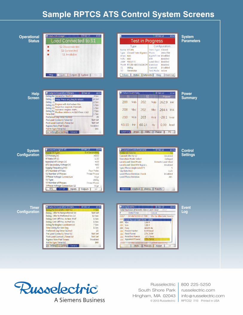
Actual ValuesActual values — measured values and control, maintenance, and fault analysis information — can be easily displayed on the RPTCS’s screen through the menu.Real-time metering of voltage (phase-to-phase and phase-to-neutral) and frequency of both normal and emergency power sources is standard. Available options include metering of phase and neutral current; percent of unbalanced current; percent of unbalanced voltage; accumulated energy (KWH, KVAH, and KVARH); and per-phase and 3-phase totals for real power (KW), apparent power (KVA), reactive power (KVAR), and power factor. All metering can be accessed through the menu.
Operational StatusThe RPTCS provides information on a switch’s operational status in the form of alarms, status messages, or general messages. Alarm messages are preceded by a red triangle and status messages by an orange square. General information messages are displayed in black text.When the controller is first powered up, the status screen will display any parameters that must be entered for proper operation of the ATS. Trips, inhibits, faults/alarms, and control messages are displayed as status messages. The operator can easily scroll through these messages using the up and down keys.
Information messages are provided in two forms: information only and information with navigation. The latter are marked with an “Enter” key on the right, which when depressed takes the operator directly to the respective screen.Status Inputs and Status Outputs screens display lists of the current state of each input or output respectively. A Status System screen shows the status of communication interfaces (serial and Ethernet).Optional upgrades allow for up to 512 lines of custom control logic programming.
System ExerciserThe RPTCS has a built-in exerciser that is set up and enabled from the Exerciser Info Screen. This feature allows the user to test the system periodically or to schedule exercises for the operating system periodically in order to minimize utility costs.The Exerciser Info screen provides access to all parameters for scheduling exercises, as well as dates for the last exercise and next scheduled one. An Exerciser Setup screen allows selection of the type of exercise and date for up to 7 events, daily, weekly, semi-monthly, or 24 events yearly. Types of exercises include Transfer of Load with Time Delay and No Transfer — Test Without Load/Generator Start Only. Unscheduled manual testing can also be performed. A “Test Cancel” button allows an operator to abort a test in progress.
DiagnosticsDiagnostics screens display information such as an event record, learned data, power summary, system counters, and system information. These screens are very helpful in diagnosing the cause of a fault or alarm.An Event Log screen lists the ten most recent events (from the event recorder) with the most recent at the top. An Event Log/Statistics screen displays date and time information as well as the reason for the last failure of the preferred source. It also provides statistics on how long the load has been in either source, how many transfers have occurred, and total time the load has been without power. A Power Summary screen displays phase rotation, voltages and angles, frequency, and phase difference for both sources. Fixed system information is displayed on the System Parameters screen. Information includes the order code, serial number, and hardware and software revision. Information on the last transfer event and load conditions at the time are presented on the Event Log screen.
Optional Wave Form CaptureThe RPTCS can also monitor power quality with available waveform capture and historical trending.
Russelectric South Shore Park
Hingham, MA 02043© 2013 Russelectric RPTCS2 7/13 Printed in USA
800 225-5250 russelectric.com info @ russelectric.com
Sample RPTCS ATS Control System Screens
System Parameters
Event Log
Control Settings
Help Screen
Power Summary
Operational Status
System Configuration
Timer Configuration