rpt on ip test sur - westam oil ltd/ventex energy ltd …
TRANSCRIPT

42D!6SWe035 63.4347 SEELEY LAKE 010
INDUCED POLARIZATION TEST SURVEYof the
WESTAM OIL LTD. - VENTEX ENERGY LTD. PROPERTY Hemlo - Marathon Region
Pic River Area Thunder Bay Mining Division
Ontario
by
R.S. Middleton, P.Eng.
3 Z*
P.O. Box 1637R.S. Middleton Exploration Services Inc.
Timmins, Ontario
March 1983
PAN 7W8

42016SWa035 63.4347 SEELEY LAKE 010C
TABLE OF CONTENTS
Page
INTRODUCTION. . . . . . . . . . . . . . . . . . . . . . lLocation and Access. .........*..... lProperty ..................... 2Topography .................... 2Survey Dates and Personnel ............ 3Previous Exploration . . . . . . . . . . . . . . . 3
SURVEY PROCEDURE and INSTRUMENTATION. . . . . . . . . . A
INTERPRETATION. . . . . . . . . . . . . . . . . . . . . 4
RECOMMENDATIONS and CONCLUSIONS . . . . . . . . . . . . 5
REFERENCES. . . . . . . . . . . . . . . . . . . . . . . 7
CERTIFICATION
APPENDIX
Specifications for IPR II
LIST OF FIGURES
Figure l Property Location Map l" - 25 mi.Figure 2 Claim Location Map l" - 1/2 mi.Figure 3 Regional Geology Bamoos Lake Sheet (2099)Figure 4 I.P. Section Line 1920SFigure 5 I.P. Section Line 2020SFigure 6 Contoured Chargeability Map
l" - 1/2 mi,

MILES
INDEX MAP

INTRODUCTION
Induced polarization profiling over a valley area on the
eastern part of the Westatn-Ventex property was carried out using
a high powered and sophisticated I.P, system in January -
February, 1984 in order to test for the presence of chargeability
anomalies that may have been missed by the first I.P. survey on
the property. The area beneath the overburden filled valley
(east of 900E on 1920S) is interpreted to contain the extension
of metasedimentary rocks that are observed north and south of the
property. This sedimentary horizon appears to be an important
regional marker for gold mineralization.
Location and Access
The Westam Oil Ltd. - Ventex Energy Ltd. claim group is
located east of the Pic River on the Seeley Lake map sheet. The
western boundary of the claim group is situated approximately
500m east of the Pic River between mileage markers 17 and 18.
Indirect road access to the Westara-Ventex property is
provided by gravel road which links mileage marker 16 on the Pic
River to highway No. 17 opposite the Marathon turn off - a
distance of 6.4 km. A 3.2 km hike along an old logging road at
mileage marker 16 on the east side of the Pic River is necessary
to reach the southern boundary of the claim group.
Direct air access to the Westam Oil Ltd. - Ventex Energy

Mile 18
From SEELEY LAKE C lo i m sheet No G 613
REVISIONS ROBERT S. MIDDLETON EXPLORATION SERVICES INC,
forWESTAM-VENTEX PROPERTY
TitleCLAIM INDEX MAP
FIG. 2Dale: NOV. 63Drawn: A.w.
Scale: l"* 2640'Approved: NC
N.T.S.: 42 D/ieFile: M-27
- 2 -
Ltd. property is provided by helicopter from a base on highway
No. 17, 7.2 km southwest in a direct line distance.
Property
The 8 contiguous mining claims included in the Westam-Ventex
claim group, encompass approximately 320 acres of mining land.
The claims are registered with the Ministry of Natural Resources,
Recording Office, Thunder Bay. The claims are listed below:
CLAIM NUMBERS TOTAL RECORDING DATE
661859 - 661866 8 5 October, 1983
At the time of writing, the claims were held in the names of
the stakers, in trust for Westam and Ventex. Work reports
covering geology, line cutting, magnetometer and induced
polarization were previously submitted covering the first two
years assessment work.
Topography
Terrain in the Pic River area is variable ranging from rock
bluffs to broad open valleys. Ridge-valley type topography is
common in the metavolcanic rock areas in the central portion of
the Pic River area in which the Westam-Ventex property is
located.
A good portion of the eastern half of the property is
covered by a thick succession of varved clays overlain by bedded
silty sands, and more recent reworked fluvial clays and sands.
Scattered outcrop comprises approximately 1 QX of the

l "v\2a,J
WESTAM- VENTEX HEMLO
PROPERTY
6a2a
lliINTRUSIVE CONTACT
BASIC TO INTERMEDIATE META- VOLCANICS AND METASEDIMENTS*"
la Dark green, fine- to medium-grainedmassive and gneissic amphibolite.
irk green, coarse-grained massiveand gneissic amphibolite.
2c Light green amphibolite and saus-surilic metavolcanic rocks,
fd Pillov, lava. le Amygdular, spherulitic or variolitic
lava.f f flovi breccia, f g Flow banded lava. 2h Tuff, slate, garnetiferous chlorite
schist, greywacke, f j Chlorite schist. Ik Banded iron formation, fm Hybrid hornblende gneiss, fn Lamprophyre, fp fihyolite. lg Biotite paragneiss.1
ACID METAVOLCANICS AND METASEDIMENTS"*
Rhyolite, porphyritic rhyolite, rhyo-litic breccia.Sericite schist.Slate, iron formation, tuff.Greywacke, tuff.Complex of metavokanic rock andintrusive alkalic gabbro, syenite andgranitic dikes.
INTRUSIVE CONTACT
YOUNGER BASIC INTRUSIVE ROCKS
6a Diabase.6b Quartz diabase.
From BAMOOS LAKE Sheet 2099
REVISIONS ROBERT S. MIDDLETON EXPLORATION SERVICES INC.
forWESTAM-VENTEX PROPERTY
Title
REGIONAL GEOLOGY
FIG. 3Date: NOV. 63Driwn: A.W
Scale: l"* 2640'Approved: NC
N.T.S.: 42 D/ttFile: M-27

- 3 -
property. The terrain is rugged in the west portion of the
property where rolling hills provide vertical relief of up to 70
metres. The metavolcanic rocks are fairly resistant and form
most of the outcropping.
Survey Dates and Personnel
I.P. readings were taken on January 26 - January 30, 1984 on
the two test lines over the valley area. The survey crew
consisted of Allan Wells, Chris Jones, David Hurst, John Scott
and Jim Bald.
Previous Exploration
In 1983 a grid consisting of a series of east-west lines was
established and a program of geological mapping, magnetometer and
induced polarization profiling was done, Caira, N., Coster, I.
(1983). A moderate I.P. anomaly trend with values up to 22
milliseconds was outlined along the east margin of the felsic
tuff raetavolcanic exposures on the east central part of the
property. This horizon was interpreted to be near the top of the
felsic sequence and therefore was interpreted as a favourable
location for gold mineralization.
No other ground work has been recorded directly on the
property although work in the general area has been done and this
has been previously described by Coster, I., and Maser, M. (1983)
and Caira, N., and Coster I. (1983).
An airborne EM and magnetic survey flown for Shell (1975)

- 4 -
covers the area of the property. The regional geology has been
described by Muir, T.L. (1982) and Milne, V.G. (1967).
SURVEY PROCEDURE and INSTRUMENTATION
The survey was done using a Scintrex IPR-II receiver and a
TSQ 3 transmitter (3 k watt). Two "a" spacings of 20 and 40
metres were used with "n"s l, 2 and 3 in a pole-dipole array
configuration. This gave theoretical survey depths up to 80
meters using the 40 metre spacing which should have been
sufficient to explore to bedrock.
A 2 second "on", 2 second "off" square wave pulse was
transmitted into the ground via steel stake electrodes and the
voltage was also read using steel stakes as potential electrodes.
A series of 10 time windows were recorded after the shut off
of the pulse and the 7th time window was plotted on the sections
which are attached to the back of this report. This time
interval is the 690 - 1050 millisecond duration after the shutoff
of the pulse.
INTERPRETATION
Line 1920S
Low surface resistivity values over the valley area on line
1920S (35-50 ohm metres) show that conductive overburden such as
clays and silts are present. The overall low resistivity values

- 5 -
are probably reflecting a metasedimentary bedrock from 940E to
1240E. A chargeability anomaly was noted on 1180E/1920S with
values up to 22.7 milliseconds which may reflect a narrow
conductive zone, possibly within the metasediments below the
valley cover. The edge of the original I.P. anomaly at 800E was
indicated on the present survey as a 27.5 millisecond anomaly at
790E and this zone occurs within the highly resistive rhyolite
tuffs.
Line 2020S
Profiling of the valley area with an "a" spacing of 40m on
line 2020 South indicated a weak 8.5 - 5.8 millisecond anomaly at
980E which may be a narrow sulphide zone within the
metasedimentary section interpreted td occur beneath the valley
floor.
RECOMMENDATIONS and CONCLUSIONS
Narrow chargeability zones were indicated by the I.P.
profiles done over the valley area on the eastern part of the
property. These sites could be tested as part of a further drill
program to cross section the interpreted sedimentary area,
specifically the areas at 1920S/1180E and 2020S/980E.
The importance of testing this sedimentary horizon stems
from the fact that a gold showing occurs within this sequence l
1/4 miles north of the Westam property. In addition this
- 6 -
horizon extends south and east of the Seeley Lake area and forms
part of the regional stratigraphy that extends west from the
Hemlo gold deposits.
Possible Drill Holes
Line 2020S/1040E - 50"W, 200m
Line 1920S/1220E - 50*.W, 200m
Respectfully submitted,
R.S. Middleton, P.Eng.

- 7 -
REFERENCES
1. Clews, D.R., and Lett, R.E.1983 Results of Surtrace Geochemical Surveys over the
Marathon and Marshall Lake Areas, District of Thunder Bay, Ontario. Geological Survey Study 25, Lake Bottom sampling program.
2. Caira, N., Coster, I.1983 Geological, Magnetometer and I.P. -Resistivity
Survey of the Westam Oil Ltd. - Ventex Energy Ltd. Property, Hemlo Marathon Gold Region, Ontario.
3. Coster, I. and Maser M.1983 Geological and Geophysical Report
on the East West Resource Corporation Property,Hemlo Marathon Gold Region,Pic River Area, Ontario, August 1983.
4. GSC - ODM1962 Aeromagnetic Map, Goodchild Creek,
2157G Scale l" - l mile
5. Milne, V.G.1967 Geology of Cirrus Lake,
Bamoos Lake Area, Ontario Department of Mines, Geological Report 43.
6. Muir, T.L.1982 Geology of the Heron Bay Area,
District of Thunder Bay, Ontario Geological Survey Report 218.
7. Phendler, P. Eng.1983 Report on the Pic River Property,
Seeley Lake - Bamoos Lake Area, Marathon, Ontario
8. Shell Minerals of Canada Ltd.,1975 Airborne Helicopter EM and
Magnetic Survey, 3 map sheetsmile, assessment file 2.2011

CERTIFICATION
I, Robert S. Middleton, P.Eng., of 136 Cedar Avenue South, in the City of Timmins, Province of Ontario, certify as follows concerning the Westam Oil Ltd.- Ventex Energy Ltd. property and dated March 31, 1984
1) I am a member in good standing of:
a) Geological Association of Canada (FGAC)b) The Association of Professional Engineers of
Ontarioc) European Association of Exploration
Geophysicistsd) Society of Exploration Geophysicistse) Canadian Institute of Mining and Metallurgy
2) I am a graduate of the Michigan TechnologicalUniversity, Houghton, Michigan, U.S.A. with a B.S. degree in Applied Geophysics obtained in 1968, and an M.S. degree in Geophysics in 1969.
3) I have been practising ray profession in Canada,occasionally in the United States, Central America, Europe and South Africa for the past 14 years.
Dated this March 31, 1984 TIMMINS, Ontario
Robert S. Middleton, P.Eng.
New from Scintrex forthe1880SEG
Broadband Time Domain IP Receiver
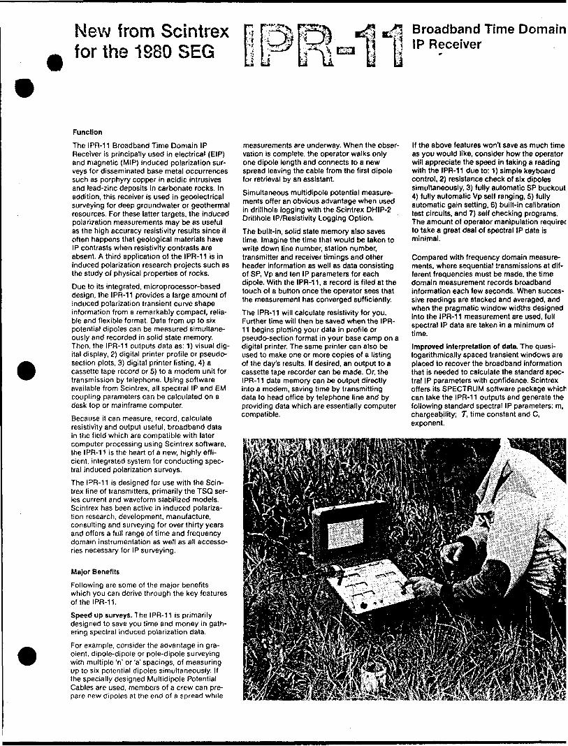
Function
The IPR-11 Broadband Time Domain IP Receiver is principally used in electrical (EIP) and magnetic (MIP) induced polarization sur veys for disseminated base metal occurrences such as porphyry copper in acidic intrusives and lead-zinc deposits in carbonate rocks. In addition, this receiver is used in geoelectrical surveying for deep groundwater or geothermal resources. For these latter targets, the induced polarization measurements may be as useful as the high accuracy resistivity results since it often happens that geological materials have IP contrasts when resistivity contrasts are absent. A third application of the IPR-11 is in induced polarization research projects such as the study of physical properties of rocks.
Due to its integrated, microprocessor-based design, the IPR-11 provides a large amount of induced polarization transient curve shape information from a remarkably compact, relia ble and flexible format. Data from up to six potential dipoles can be measured simultane ously and recorded in solid state memory. Then, the IPR-11 outputs data as: 1) visual dig ital display, 2) digital printer profile or pseudo- section plots, 3) digital printer listing, A ) a cassette tape record or 5) to a modern unit for transmission by telephone. Using software available from Scintrex, all spectral IP and EM coupling parameters can be calculated on a desk top or mainframe computer.
Because it can measure, record, calculate resistivity and output useful, broadband data in the field which are compatible with later computer processing using Scintrex software, the IPR-11 is the heart of a new, highly effi cient, integrated system for conducting spec tral induced polarization surveys.
The IPR-11 is designed for use with the Scin trex line of transmitters, primarily the TSQ ser ies current and waveform stabilized models. Scintrex has been active in induced polariza tion research, development, manufacture, consulting and surveying for over thirty years and offers a full range of time and frequency domain instrumentation as well as all accesso ries necessary for IP surveying.
Major Benefits
Following are some of the major benefits which you can derive through the key features of the l PR-11.
Speed up surveys. The IPR-11 is primarily designed to save you time and money in gath ering spectral induced polarization data.
For example, consider the advantage in gra dient, dipole-dipole or pole-dipole surveying with multiple 'n' or 'a' spacings, of measuring up to six potential dipoles simultaneously. If the specially designed Multidipole Potential Cables are used, members of a crew can pre pare new dipoles at the end of a spread while
measurements are underway. When the obser vation is complete, the operator walks only one dipole length and connects to a new spread leaving the cable from the first dipole for retrieval by an assistant.
Simultaneous multidipole potential measure ments offer an obvious advantage when used in drillhole logging with the Scintrex DHIP-2 Drillhole IP/Resistivity Logging Option.
The built-in, solid state memory also saves lime. Imagine the time that would be taken to write down line number, station number, transmitter and receiver timings and other header information as well as data consisting of SP, Vp and ten IP parameters for each dipole. With the IPR-11, a record is filed at the touch of a button once the operator sees that the measurement has converged sufficiently.
The IPR-11 will calculate resistivity for you. Further time will then be saved when the IPR- 11 begins plotting your data in profile or pseudo-section format in your base camp on a digital printer. The same printer can also be used to make one or more copies of a listing of the day's results. If desired, an output to a cassette tape recorder can be made. Or, the IPR-11 data memory can be output directly into a modern, saving time by transmitting data to head office by telephone line and by providing data which are essentially computer compatible.
If the above features won't save as much time as you would like, consider how the operator will appreciate the speed in taking a reading with the IPR-11 due to: 1) simple keyboard control, 2) resistance check of six dipoles simultaneously, 3) fully automatic SP buckout, 4) fully automatic Vp self ranging, 5) fully automatic gain setting, 6) built-in calibration test circuits, and 7) self checking programs. The amount of operator manipulation required to take a great deal of spectral IP data is minimal.
Compared with frequency domain measure ments, where sequential transmissions at dif ferent frequencies must be made, the time domain measurement records broadband information each few seconds. When succes sive readings are stacked and averaged, and when the pragmatic window widths designed into the IPR-11 measurement are used, full spectral IP data are taken in a minimum of time.
Improved Interpretation of data. The quasi- logarithmically spaced transient windows are placed to recover the broadband information that is needed to calculate the standard spec tral IP parameters with confidence. Scintrex offers its SPECTRUM software package which can take the IPR-11 outputs and generate the following standard spectral IP parameters: m, chargeability; T, t ime constant and C, exponent.

Broadband Time Domain IP Receiver
Interpretability of spectral IP data are improved since time domain measurements are less affected by electromagnetic coupling effects than either amplitude or phase angle frequency domain measurements, due to the relatively high frequencies used in the latter techniques. In the field, coupling free data are nearly always available from the IPR-11, by simply using chargeability data from the later transient windows. Then, in the base camp or office, the Scintrex SPECTRUM computer program may be used to resolve the EM com ponent for removal from the IP signal. The electromagnetic induction parameters may also be interpreted in order to take advantage of the information contained in the EM component.
A further advantage of the IPR-11 in interpret ing spectral IP responses is the amount of data obtainable due to the ability to change transmitted frequencies (pulse times) and measurement programs by keypad entry.
Enhance signal/noise. In the presence of ran dom (non-coherent) earth noises, the signal /noise ratio of the IPR-11 measurements will be enhanced by IN where N is the number of individual readings which have been averaged to arrive at the measurement. The IPR-11 automatically stacks the information contained in each pulse and calculates a running aver age for Vp and each transient window. This enhancement is equivalent to a signal increase of ffi, o r a power increase of N. Since N can readily be 30 or more (a 4 minute observation using a 2 second on/off waveform), the signal /noise improvement reaped by the IPR-11 cannot be practically achieved by an increase in transmitter power. Alternatively, one may employ much lower power transmitters than one could use with a non-signal enhancement receiver.
The automatic SP program bucks out and cor rects completely for linear SP drift; there is no residual offset left in the signal as in some pre vious time domain receivers Data are also kept noise free by: 1) automatic rejection of spheric spikes, 2) 50 or 60 Hz powerline notch filters, 3) low pass filters and 4) radio fre quency (RF) filters. In addition, the operator has a good appreciation of noise levels since he can monitor input signals on six analog meters, one for each dipole. Also, with the Optional Statistical Analysis Program, he can monitor relative standard error continuously on the digital display and then file these calcu lations in the data memory when the observa tion is complete.
Noise free observations can usually be made using the self-triggering feature of the IPR-11. The internal program locks into the waveform of the signal received at the first dipole (near est a current electrode) and prevents mistrig- gering at any point other than within the final 25 percent of the current on time. In particu larly noisy areas, however, synchronization of
the IPR-11 and transmitter can be accomp lished either by a wire link or using a high sta bility, Optional Crystal Clock which fits onto the lid of the instrument.
Reduce Errors. The solid state, fail-safe memory ensures that no data transcription errors are made in the field. In base camp, data can be output on a digital printer or a read-after-write cassette tape deck and played back onto a digital printer for full verification. The fact that the IPR-11 calculates resistivity from recorded Vp and l values also reduces error.
The self check program verifies program integrity and correct operation of the display, automatically, without the intervention of the operator. If the operator makes any one of ten different manipulation errors, an error, mes sage is immediately displayed.
The Multidipole Potential Cables supplied by Scintrex are designed so there is no possibility of connecting dipoles to the wrong input ter minals. This avoids errors in relating data to the individual dipoles. The internal calibrator assures the operator that the instrument is properly calibrated and the simple keypad operation eliminates a multitude of front panel switches, simplifying operation and reducing errors.
Features
Six Dipoles Simultaneously. The analog input section of the IPR-11 contains six identical dif ferential inputs to accept signals from up to six individual potential dipoles. The amplified analog signals are converted to digital form, multiplexed and recorded with header infor mation identifying each group of dipoles. Custom-made multidipole cables are available for use with any electrode array.
Memory. Compared with tape recording, the IPR-11 solid state memory is free from prob lems due to dirt, low temperatures, moving parts, humidity and mechanical shock. A bat tery installed on the memory board ensures memory retention if main batteries are low or if the main batteries are changed. The following data are automatically recorded in the memory for each potential dipole: 1) receiver timing used, 2) transmitter timing used, 3) number of cycles measured, 4) self potential (SP), 5) primary voltage (Vp) and 6) ten transient IP windows (Mj). In addition, the operator can enter up to seventeen, four digit numerical headers which will be filed with each set of up to six dipole readings. Headers can include, for example, line number, station number, operator code, current amplitude, date, etc.
In the standard data memory, up to 200 poten tial dipole measurements can be recorded. Optional Data Memory Expansion Blocks can be installed in the IPR-11 to increase memory capacity in blocks of about 200 dipoles each to a total of approximately 800 dipoles. Memory capacities will be reduced somewhat if the Optional Statistical Analysis Program is used.

Memory Recall. Any reading in memory can be recalled, by simple keypad entry, lor inspection on the visual display. For example, the operator can call up sequential visual dis play of all the data filed for the previous obser vation or for the whole data memory.
Carefully Chosen Transient Windows. TheIPR-11 records all the information that is really needed to make full interpretations of spectral IP data, to remove EM coupling effects and to calculate EM induction parameters. Ten quasi- logarithmically spaced transient windows are measured simultaneously for each potential dipole over selectable total receive times of 0.2,1.0, 2.0 or 4.0 seconds.
After a delay from the current off time of t, the width of each of the first four windows is t, of the next three windows is 6t and of the last three windows is 12t. The t values are 3,15, 30 or 60 milliseconds. Thus, for a given dipole, up to forty different windows can be measured by using all four receive times. The only restric tion is, of course, that the current off time must exceed the total measuring time. Since t is as low as 3 milliseconds and since the first four windows are narrow, a high density of curve shape information is available at short times (high frequencies) where it is needed for confident calculation of the spectral IP and EM coupling parameters.
Calculates Resistivity. The operator enters the current amplitude and resistivity geometry (K) factors in header with each observation. If the K factors remain the same, only a code has to be entered with each observation. Then, using the recorded Vp values, the IPR-11 calculates the apparent resistivity value which can be output to the printer or cassette tape recorder.
Normalizes lor time and Vp. The IPR-11 divides the measured area in each transient window by the width of the window and by the primary voltage so that values are read out in units of millivolts/volt (mils).
Signal Enhancement. Vp and M values are continuously stacked and averaged and the display is updated for each two cycles. When the operator sees that the displayed values have adequately converged, he can terminate the reading and file all values in memory.
-T
Vp Integration. The primary voltage is sampled over 50 percent or more of the current on (T) time (depending on receive time) and the result is normalized for time. This long integra tion helps overcome random noise. On stand ard Scintrex transmitters, T can be 1,2,4 or 8 seconds.
Digital Display. Two, four digit LCD displays are used to display measured or manually entered data, data codes and alarm codes.
Automatic Profile Plotting. When connected to a digital printer such as the Scintrex DP-4 hav ing an industry standard RS-232C, 7 bit ASCII serial data port, data can be plotted in a base camp. The IPR-11 is programmed to plot any selected transient window and resistivity in pseudo-section or profile form. Line orienta tion is maintained consistent, that is station numbers on profiles are sorted in ascending number. In the profile plot, the scale for resis tivity is logarithmic with 1 to 10,000 ohmme- ters in four decades with another four decades of pverrange both above and below. The char geability scale is keypad selectable. In the pseudo-section plot, any one chargeability window can be presented in conventional pseudo-section form.
Printed Data Listing. The same digital printer can be used to print out listings of all headers and data recorded during the day's operation. Several copies can be made for mailing to head office or for filing in case copies are lost. Baud rate is keypad selectable at 110, 300 or '1200 baud, depending on the printer used.
Cassette Tape Output. A cassette recorder having an industry standard RS-232C, 7 bit ASCII serial interface may be used for storing data directly from the IPR-11. If all six dipoles are used, then 16,80 character blocks of data per observation are transferred at a rate of 1200 baud. The storage capacity of one side of cassette tape is approximately 1400 blocks or about 90 six dipole observations. The MFE Model 2500 is recommended since it has a read-after-write feature for data verification.
The recording format is compatible with the Texas Instruments 'Silent 700' terminals and records are made on standard digital grade cassettes. Once a cassette tape record is made, the tape can be played back onto the DP-4 Digital Printer for an additional verifica tion that the data on tape are correct.
Time domain IP transmuted waveform
Pseudo-section printout on DP-4 Digital Printer. Chargeability date ere shown lor the sixth transient window (Ms) lor the dipole-dipole array and six 'n' spacings. Line number and station number are also recorded. The contours have been hand drawn. Resistivity results can be plotted in e similar manner.
: - a
J* n ; i i
l! ;2 23 ;
21 22 2' l
12 22 23 l
16 22 25 !
27 IS 2f j
If 21 27 l
17 24 27 l
21 24 27 l
22 25 27 l
27 27 25 l
25 24 27 l
*0 25 2! 21 I
Jlv, 25 -J( l
\\N t, 2, ,
*0S"\ Sis 23 !
\ *4\s 11\^ 23 l
57 \ ,\ ^ ,
. X \ \X " \ H \ 2 ' '
' o. X \ \ x50Ck V^ \" \'
0 ^- X S * ', 0 xv s*'\ *' ' l e '
I(\ ^ ^ 3 ''\ \ ! NV ~ - '* o ; z-"t f i' X 'if ' /s3J' .21 l
jo' s / \
^/? /"} Y"s;/./- l " y
o s *t 3 ! 31 l
*3 y 3:1 X/ '
45 x/ 34 f' li l/ '

Broadband Time Domain IP Receiver
SENS: 8.2rftWDIV CHL:3 SLC:5
4. Ei - 6 * 4. e
E+l E+2 E+3
: : fi 6
: : R B :
: : R 6 :
: : R 6 :: : R 8 :
: : R S :
: : F; 6 : * P P
: : R fi :
8.8
Er4 LINE SIN
: R 6: R
: R
: R
: R 8: R e- P e
RroWe printout on DP-4 Digital Printer.
li 6.l 7.i 8.i 9.i ial il.
l 14.l 15I 16.1. 17.l IR
i148.2
X; 9
8 5o^ ^V.L 0
7 97 IS
7 -?
7 f* f:
6. 3 5. 3-7 J 71T4.7
6.4 5.2fi s. 7Et3
f. K C: S
-4. 3. 46E*35. 9 4. 9
"K
4
4.
4
d
i K;-- 777-5
6 3. 4 2.
6 3. 3 2.
4 3. 3 2.
7 7 2 2
K/S7 Si97 j^724
17 13 S. 9
17 13 ft 9
17 i. 2 ft 9
t. j i. 7 fi o
3292
0.7
6.7
e. 7
9744. 5? 4. 1 49Et3
s- 71 5 fi 41 7 t, v c! i fi li 18 12 18
22 43 -2. 2 64Et3f.- 3 5 7 g 5. fi 5. l 37 2. 7 2. 2 i. 5 ft 6 8. 4
Modem. Data in the IPR-11 memory can be output directly into a modem near the field operation and transmitted by telephone through a modern terminal in or near head office, where data can be output directly onto a digital printer or tape recorder. In this way a geophysicist in head office can receive regular transmissions of data to improve supervision and interpretation of the data from field pro jects and no output device other than the modern is required in the field.
External Circuit Check. Six analog meters on the IPR-11 are used to check the contact res istance of individual potential dipoles. Poor contact at any one electrode is immediately apparent. The continuity test uses an AC sig nal to avoid electrode polarization.
Self Check Program. Each time the instrument is turned on, a check sum verification of the program memory is automatically done. This verifies program integrity and if any discre pancy is discovered, an error signal appears on the digital display. Part of the self check program checks the LCD display by displaying eight ones followed sequentially by eight twos, eight fours and eight eights.
Manipulation Error Checks. Alarm codes appear on the digital display if any of the fol lowing ten errors occur: tape dump errors, illegal keypad entry, out of calibration or failed memory test, insufficient headers, header buffer full, previous station's data not filed, data memory full, incorrect signal amplitude or excessive noise, transmit pulse time incorrect and receiver measurement timing incorrect.
Internal Calibrator. By adjustment of the func tion switch, an internal signal generator is connected across the inputs to test the calibra tion of all six signal inputs for SP, Vp and all M windows simultaneously. Then the software checks all parameters. If there is an error in one or more parameters, an alarm code appears on the display. The operator can then push a key to scan all parameters of all input channels to determine where the error is.
Data listing output on DP-4 Digital Printer, Header information /s shown in the first two lines. In this case, data are lor Line 1, Station 3. Transmitted cur rent is 80 mA. Next are the resistivity K factors for the six dipoles. 8292 indicates that receive and transmit times are each 2 seconds. The last header item records that tact that 14 cycles were stacked. Following the header are the geophysical data lor six dipoles which were measured simultaneously. For each dipole, the values for the 10 transient windows are shown on one line. The next line shows Vp and SP in mVIV and resistivity. 5.71 E -f 3 indicates that the calculated resistivity is 5.71 x 10 3 ohm-metres.

Automatic SP Correction. The initial self potential buckout is entirely automatic - no adjustment need be made by the operator. Then, throughout the measurement, the IPR- 11 slope correction software makes continual corrections, assuming linear SP drift during a transmitted cycle. There is no residual SP offset included in the chargeability measure ment as in some previous time domain receivers.
Automatic Vp Self Ranging. There is no man ual adjustment for Vp since the IPR-11 auto matically adjusts the gain of its input amplifi ers for any Vp signal in the range 100 microvolts to 6 volts.
Spheric Noise Rejection. A threshold, adjusta ble by keypad entry over a linear range of O to 99, is used to reject spheric pulses. If a spheric noise pulse above the set threshold occurs, then the IPR-11 rejects and does not average the current two cycles of information. An alarm code appears on the digital display. If the operator continues to see this alarm code, he can decide to set the threshold higher.
Powerllne and Low Pass Filter. An internal switch is used to set the IPR-11 for either 50 or 60 Hz powerline areas. The notch filter is automatically switched out when the 0.2 second receive time is used since the filters would exclude EM signals.
RF Filter. An additional filter in the input cir cuits ensures that radio frequency interference is eliminated from the IPR-11 measurement.
Input Protection. If signals in excess of 6 V and up to 50 V are applied to any input circuit, zener diode protection ensures that no dam age will occur to the input circuits.
Synchronization. In normal operation, the IPR- 11 synchronizes itself on the received wave form, limiting triggering to within 2 ,5Vt* of the current on time. However, for operation in locations where signal/noise ratios are poor, synchronization can be done either by running a cable from the transmitter or by using the Optional Crystal Clock which can be installed in the lid of the IPR-11.
Optional Statistical Analysis. As an option, the IPR-11 can be provided with software to do statistical analysis of some parameters. The relative standard error is calculated, displayed on the LCD display and may be recorded in data memory. The total capacity of data memory will be reduced, depending on the extent of statistical data recorded. If the Optional Statistical Analysis Program is chosen, some thought should be given to pur chasing one or more blocks of Data Memory Expansion.
Software for EM Coupling Removal. In tran sient measurements, the EM coupling compo nent occurs closest to the current off time (i.e. it is primarily in the early windows). Thus, it is
usually possible to obtain coupling-free IP data simply by using the later windows of the IPR-11 measurement program. If, however, full spectral information is desired, the data from the early windows must be corrected for the EM component. This can be done with confi dence using a desk top of mainframe compu ter and the Scintrex SPECTRUM program.
Software for Spectral IP Parameters. Using the chargeability data from the ten quasi- logarithmically spaced IPR-11 windows, a desk top or mainframe computer and the Scin trex SPECTRUM program, spectral IP parame ters can be calculated. The basis for this calcu lation as well as for the EM coupling removal calculation is discussed in a technical paper by H.O. Seigel, R. Ehrat and l. Brcic, given at the 1980 Society of Exploration Geophysicists Convention, entitled "Microprocessor Based Advances in Time Domain IP Data Collection and In-Field Processing".
Operation
In relation to the efficiency with which it can produce, memorize, calculate and plot data, the IPR-11 is quite simple to operate, using the following switches and keypad manipulations.
Power On-Off. Turned on to operate the instrument.
Reset. Resets the program to begin again in very poor signal/noise conditions.
Function Switch. Connects either the potential dipoles or the internal test generator to the
input amplifiers or connects the external cir cuit resistance check circuitry to the potential dipoles.
Keypad. The ten digit and six function keys are used to: 1) operate the instrument, 2) enter information, 3) retrieve any stored data item for visual display, and 4) output data on to a digital printer, cassette tape deck or modem. Examples of some of these manipulations, most of which are accomplished by three key strokes, follow. E is the general entry key.
A concise card showing the keypad entry codes is attached inside the lid of the l PR-11
Example 1. Keying 99E commands the battery test. The result is shown on the digital display.
Example 2. Keying 90E tells the l PR-11 to use the 0.2 second receive time. 91, 92 and 94 cor respond to the three other times. x
Example 3. Keying 12M results in the display of the chargeability of the first dipole, window number 2, during the measurement. Similarly, 6SP or 4 Vp would result in the display of the SP value in the sixth dipole or Vp in the fourth dipole respectively.
Example 4. Keying NNNNH, where N is a vari able digit, records an item of header informa tion. Seventeen such items can be entered with each file of up to six dipoies of data.
Example 5. 73E, 74E or 75E are used to output the data from the memory to the digital printer or modern at 110, 300 or 1200 baud respectively.
Nominal total receive time: 0.2,1,2,4 sec.-H
x \ iM
t t t t 6t 6t 6t 12t
IPR-11 transient windows
12t
Mg
I2t Window Width

Broadband Time Domain IP Receiver
IPR-11 Options
The following options are available for pur chase with the IPR-11.
Multldipole Potential Cables. These cables are custom manufactured for each client, depend ing on electrode array and spacings which are to be used. They are manufactured in sec tions, with each section a dipole in length and terminated with connectors. For each observa tion, the operator need only walk one dipole length and connect a new section, in order to read a new six dipole spread. There is no need to move the whole spread. The connectors which join the cables are designed so that there is no possibility of connecting the wrong dipole to the wrong input amplifier. The out side jacket of these cables is rubber which is flexible at low temperatures. About 5 percent extra length is added to each section to ensure that the cable reaches each station.
Data Memory Expansion Blocks. The standard data memory of the IPR-11 allows for data for up to 200 dipole measurements to be recorded, assuming a common header for six dipoles. Up to three additional memory blocks can be installed in the instrument, each of about 200 dipole capacity.
Statistical Analysis Program. Scintrex can pro vide, in EPROM, a statistical program to give real time calculations of relative standard error of one or more parameters.
Crystal Clock. Scintrex can provide a high stability clock to synchronize the IPR-11 with a similar clock in the transmitter. This option is, however, only required for work in extremely noisy and/or low signal environments.
Software. Scintrex offers its SPECTRUM pro grams for EM coupling removal, calculation of EM induction factors and calculation of the spectral IP parameters.
Digital Printer. The Scintrex DP-4 Digital Prin ter is a modified Centronics Microprinter with an RS-232C, 7 bit ASCII serial port. It is a self contained module, including 110/230 V power supply, control electronics and printing mech anism. It produces copy on aluminum coated paper by discharging low voltages through tungsten styli. Characters are formed from the appropriate dots of a 5 x 7 dot matrix. All 96 standard ASCII characters are available, the paper width is 120 mm and 80 characters can be printed per line at a rate of up to 150 lines per minute.
Cassette Tape Recorder. The MFE Model 2500 with read-after-write verification is recom mended. It has an RS-232C, 7 bit ASCII serial interface with a recording format compatible with the Texas Instruments 'Silent 700' The cassBtte lafe "*corrfnp format of the IPR-11 is terminals compatible with the Texas Instruments Silent 700
terminals which can be used tor printing out, editing,Modem. A number of modern units are available - copying tapes or transmitting data to a similar termi- on the market which are compatible with the nal using lelePhone lines- IPR-11. Scintrex would be pleased to recom mend or supply such equipment if required.
The takeouts ol the Multidipole Potential Cables allow lor connection to a porous pot or other elec trode as well as lor connection o! the next section ol cable, usually one dipole in length.
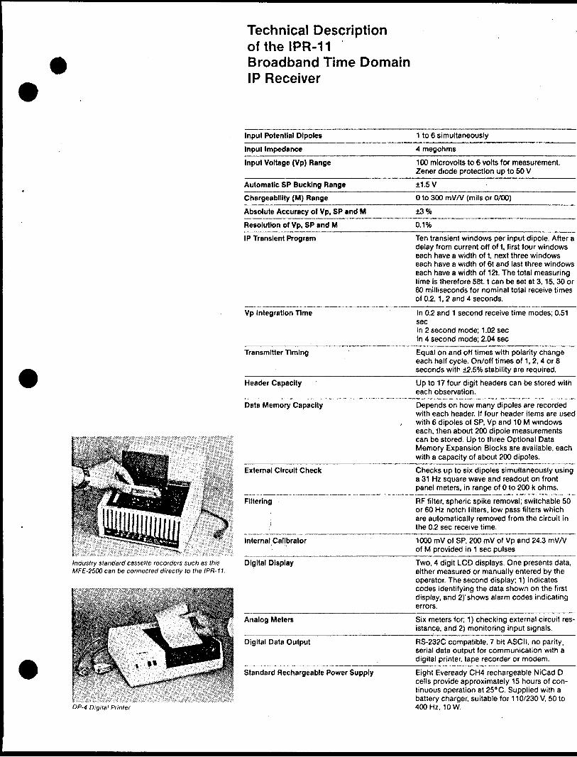
Technical Description ofthelPR-11 Broadband Time Domain IP Receiver
Input Potential Dlpoles
Input Impedance
Input Voltage (Vp) Range
Automatic SP Bucking Range
Chargeability (M) Range
Absolute Accuracy of Vp, SP and M
Resolution of Vp, SP and M
IP Transient Program
Vp Integration Time
Transmitter Timing
Header Capacity
Data Memory Capacity
External Circuit Check
Filtering
Internal Calibrator
Industry standard cassette recorders such as this D igital D isplay MFE-2500 can be connected directly to the l PR-11.
Analog Meters
Digital Data Output
Standard Rechargeable Power Supply
DP-4 Digital Printer
1 to 6 simultaneously
4 megohms
100 microvolts to 6 volts for measurement. Zener diode protection up to 50 V
1.5V
O to 300 mV/V (mils or 0/00)
3'/o
0.1 "(4
Ten transient windows per input dipole. After a delay from current off of t, first four windows each have a width of t, next three windows each have a width of 6t and last three windows each have a width of 12t. The total measuring time is therefore 58t. t can be set at 3,15, 30 or 60 milliseconds for nominal total receive times of 0.2,1, 2 and 4 seconds.
In 0.2 and 1 second receive time modes; 0.51secIn 2 second mode; 1.02 secIn 4 second mode; 2.04 sec
Equal on and off times with polarity change each half cycle. On/off times of 1,2, 4 or 8 seconds with 2.50Xo stability are required.
Up to 17 four digit headers can be stored with each observation.
Depends on how many dipoles are recorded with each header. If four header items are used with 6 dipoles of SP, Vp and 10 M windows each, then about 200 dipole measurements can be stored. Up to three Optional Data Memory Expansion Blocks are available, each with a capacity of about 200 dipoles.
Checks up to six dipoles simultaneously using a 31 Hz square wave and readout on front panel meters, in range of O to 200 k ohms.
RF filter, spheric spike removal; switchable 50 or 60 Hz notch filters, low pass filters which are automatically removed from the circuit in the 0.2 sec receive time.
1000 mV of SP, 200 mV of Vp and 24.3 mV/V of M provided in 1 sec pulses
Two, 4 digit LCD displays. One presents data, either measured or manually entered by the operator. The second display; 1) indicates codes identifying the data shown on the first display, and 2)' shows alarm codes indicating errors.
Six meters for; 1) checking external circuit res istance, and 2) monitoring input signals.
RS-232C compatible, 7 bit ASCII, no parity, serial data output for communication with a digital printer, tape recorder or modern.
Eight Eveready CH4 rechargeable NiCad D cells provide approximately 15 hours of con tinuous operation at 25"C. Supplied with a battery charger, suitable for 110/230 V, 50 to 400 Hz, 10 W.

Technical Description ofthelPR-11 Broadband Time Domain IP Receiver
Disposable Battery Power Supply
Optional Items
At 250 C, about 40 hours of continuous opera tion are obtained from 8 Eveready E95 or equivalent alkaline D cells.
At 25e C, about 16 hours of continuous opera tion are obtained from 8 Eveready 1150 or equivalent carbon-zinc D cells.
Dimensions
Weight
Operating Temperature Range
Storage Temperature Range
Standard Items
345 mm x 250 mm x 300 mm, including lid.
10.5 kg, including batteries.
-20 to *55"C, limited by display.
-4010+60" C.
Console with lid and set of rechargeable bat teries, 2 copies of manual, battery charger.
Multidipole Potential Cables, Data Memory Expansion Blocks, Statistical Analysis Pro gram, Crystal Clock, SPECTRUM Program.
Shipping Weight 25 kg includes reusable wooden shipping case.
222 Snidercroft Road Concord Ontario Canada L4K 1B5
Telephone: (416) 669-2280 Cable: Geoscint Toronto Telex: 06-964570
Geophysical and Geochemical Instrumentation and Services
IPR-11 LCD displays, actual size

469422
66
18
58
E
AS
T-W
ES
T
RE
SO
UR
CE
L 1
92
0S
WE
ST
-l A
z.27
00
Dip
- 5
50
Leng
th
191
m
WE
ST
-3A
z. 2
700
Dip
-50
0
Leng
th 1
19m
CL
AIM
IN
DE
X
MA
P
l"-1
/2 m
tl*
66
,866
EA
ST V
.EST
R
ESO
UR
CE
U2O
4O
S
L 2
I6O
S
WE
ST
-2
Az.
270
0 D
ip-4
50
Leng
th 1
22 n
L2
28
OS
L2
4O
OS
L2
64
OS
DR
ILLE
D
BY!
MID
WES
T D
RIL
LIN
G ,
f In
di p
t g, B
an.
TOTA
L FO
OTA
6E:
I4l7
'(432ii)
NQ C
ORE
LOGG
ED tf
R.
BAL
D
66
37
98
D
OR
E
EX
PL
OR
AT
ION
S6
61
86
9
BO
RA
M
OIL
66
18
70
B
OR
AM
O
ILR
EV
ISIO
NS
RO
BE
RT
S.
MID
DL
ET
ON
E
XP
LO
RA
TIO
N S
ER
VIC
ES
IN
C6
61
87
1
BO
RA
M O
IL6
61
87
2
BO
RA
M O
IL
l
WE
ST
AM
O
IL
LT
D.
Tit
le
SE
ELE
Y
LAK
E A
RE
ATH
UN
DE
R B
AY
MIN
ING
DIV
ISIO
N
DIA
MO
ND
DR
ILL
LOC
ATIO
N
MAP
ScaE
e I-2
50O
N.T
.S.:4
2DX
I6A
ppro
ved:
File
: M
-27
4a0165W
e*3
5
63.4
347
SE
ELE
Y
LA
KE

(D IV) O(fi
N Q
3OOS
3OO9
3OO8
3OOO/
688-910 PENNANT^688908 PENNANT RESOURCES
3 O OS/
3OO9J
ro o ro oCO
'
O
x1
H* **M
S
(O
R
r"3 l* ^ 15? o
2 P in
m
J75
m2)
DO3)00DBjm
z co
ii O)
z o
CL O
3) H x xl l
st * a
m o c-OO A OS
m ,s? -3 f H
gO) m
5. J5
.oc
oM-— J. O2
r m-i,
i — '
aN^5O
J: \)

RE
SIS
TIV
ITY
o
hm
/m
740E
76
0 78
0 80
0 82
0 84
0 86
0 88
0 90
0 92
0 94
O
960
980
1000
10
20
1040
10
60
1080
11
00
1120
11
40
1160
11
80
1200
12
20
1240
E
i i
i i
i i
i i
i i
i i
i i
i t
i i
i i
i i
i i
i i
i
:O
780
42D16SW0035 63.4347 SEELEY LAKE
22
0
i i
i i
i
1000
CH
AR
GE
AB
ILIT
Y
m v
/v
1000
10
20
1040
10
60
1080
11
00
1120
11
40
1160
11
80
1200
1240
E
o.o
.
I ^o
. ^
-o
.^a
.x
?-7
-fc
fc-g
-/-z
o
IND
UC
ED
P
OLA
RIZ
AT
ION
time
dom
ain
mod
e
PO
LE
DIP
OLE
A
RR
AY
JD
p^
Dp
5..D
p4,
:Dp
3..
Dp
2iD
p|
\
v S
"*~
V
K
Nn
PL
OT
P
OIN
TS
A -
20
m-
Ns
U3
Tx.
Rx.
SCIN
TREX
m
odel
, TS
Q-3
(3
Kw)
2s
ec. o
n, 2
sec.
off
SCIN
TREX
m
odel
, IP
R-II
2 se
c. m
ode
, m
v/V
slic
e
Tota
l lin
e 520
m.
Tota
l R
eadi
ngs
^.4O
20
AA
-
Met
ros
RE
VIS
ION
SR
OB
ER
T S
. M
IDD
LETO
N
EX
PLO
RA
TIO
N S
ER
VIC
ES
IN
C,
for
WES
TAM
- V
EN
TEX
Tit
le
Dat
e: F
EB.
1984
pra
wn
:AW
7CG
L 19
20 S

RE
SIS
TIV
ITY
ohm
/m
IND
UC
ED
P
OLA
RIZ
AT
ION
time
dom
ain
mod
e8
60
E12
60 E
1340
El
1
1 1
1 1
1
1 1
.1
1
1
1
1 1
1
1 1
A.
1 1
1 1
1 1
1 1
1 1
11
1
I II
1 1
1 1
1 1
I 1
1 1
1 1
1 .J
..-.
-J.IB
I,-1
\
^R
X100
tf5-
ZW
./y
vV
?-^
45
'2-
5Q-3
5^
--/
' 35
". S
6J
- -5
6
^3
&
0-S
6
Z-o
66
-5"
8l^/ ll
o.
.
400—
— ^^v
t ^^^^
^^
4S
O.}
Z70
. A
w^^o-
5^'
^s:-?
^ -?
-^
C/^
^^^'S
n*f
33
*^ ^
w
:
-W S
JIO
' 3d* /^
c^\^t
S
^'^
^
"3
^'*
^
f /J
S'7
X
38.6
- /2
V
/^'
/7/'
-
. .p
o/
. -X
/
-W
^'
. .
. ^.
. .
. .
. .
. .
- .
. .
- .
- -
- .
.• •' .'t* •••*.l.
. .
. .•.•..••••* ,*-. ,**...
. - .,
t
'
CH
AR
GE
AB
ILIT
Y
m v
/v
860
E 94
0E
I020
E
I100
E
1I80
E
I260
E
1340
E1 _
____ 1 —
——
——
i 1 _
____ 1 _
__
__
1 _____ 1 —
——
——
1 _____ 1 _
__
__
1 _____ 1 _
__
__
1 _____ 1 _
__
__
1 _____ 1 _
____ 1 _
__
__
1 __
__
_ 1 _
____ 1 —
——
——
1 _____ 1 —
——
——
1 ——
——
— 1 —
——
——
1 ——
——
— 1 —
——
——
1 ——
——
— 1 —
——
——
1 ——
——
— 1 —
——
——
1 ——
——
— 1 —
——
——
1 ——
——
— 1 —
——
——
1 ——
——
— 1 —
——
——
1 ——
——
— 1 —
——
— -
1 ——
——
— 1 —
——
——
1 ——
——
— 1 —
——
——
1 ——
——
— 1 —
——
——
1 ——
——
— 1 —
——
——
l ——
——
— l —
——
——
J
\v\V
\
f-3
.0
\ /.
?\s
\d-o
^O
t.i
a*S
o
. s
o-5
}
-1
*-l
V'S
a
-5
0-3
^*?
[
-0-2
^ -
\
^V
\
\\
N^
rUL
t U
IKU
Lt
AR
RA
T
v i
10o6iD
o3lD
p4lO
D3lD
p2lD
pl
1—
——
——
K —
— tZ
^ —
E —
— --
e —
— —
C —
— —
E —
— —
K —
— V
——
— J—
——
— —
——
——
——
——
——
——
——
——
——
——
——
——
——
——
——
——
——
——
——
——
——
——
——
——
——
——
——
——
——
——
——
-1.
\
^ "
^ v O
/
\ \
*\ \
\ y*
^ \ \ \
X"*
^ x
\ N
. s
\
,"n3
N
v \
\,'
PLO
T P
OIN
TS^
\
,' n
* \
;"n5
*'
A s
4
0
Ns
1.2.
3V
n6
m
——
——
"
— '
IY
——
65
^^~
)
Tx.
SCIN
TREX
m
odel
, TS
Q-3
(3
Kw)
2 s
ec. o
n, 2
sec.
off
Rx.
SCIN
TREX
m
odel
, IP
R-II
2
sec.
mod
e ,
mv/
V s
lice
ft 7
Tota
l lin
e 52
0 m
Toto
i Re
adin
g?.,.
!?..
.10
0 60
20
0
50
(GO
^-D
-4
-0"4
1\
-3-3
Q 0.7
,*
-3-5
-/-
51
/-7
1-5
O-O
RE
VIS
ION
SR
OB
ER
T S
. M
IDD
LETO
N
EX
PLO
RA
TIO
N S
ER
VIC
ES
IN
C,
for
WES
TAM
-VEN
TEX
Tit
le
L 2
02
0S
Dat
e:
FEB.
1984
42D16SW8035 63.4347 SEELEY LAKE
23
0D
raw
n: C
J 7 A
WA
ppro
ved:
Scal
e: l
250
0 l N
T. S,
: 42 D
16