rpt on geol work & linecutting performed on road prop
TRANSCRIPT

l -' l
t2A08NEe840 63.3789 GUIBORD ~, 010
K/.- tf 7
REPORT ON
GEOLOGICAL WORK AND LINECUTTING
PERFORMED ON
ROAD PROPERTY
GUIBORD TOWNSHIP, MATHESON AREA,
LARDER LAKE MINING DIVISION - ONTARIO
FOR
ARMCO MINERAL EXPLORATION LTD.
BY
PETER G. ATHERTON B.Sc.
H. E. NEAL 6 ASSOCIATES LTD.
TORONTO - CANADA
December, 1980
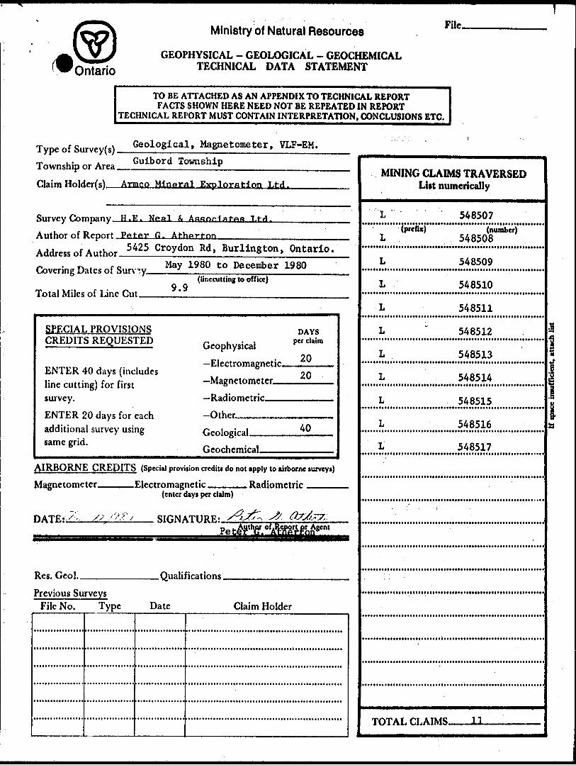
This report on the linecutting and geological survey is submitted under the special provisions dated October 16, 1967 for the credit of 40 assessment work days per claim.
1.0 SUMMARY:
A four man crew conducted linecutting and a geological survey on the
Road Property in Guibord Township between May 22 and June 24, 1980.
The survey only located two outcrops along the Pike River so the
geological interpretation is based on the results of the geophysical
surveys and by observing outcrops on surrounding properties. The
resulting interpretation indicated the location of the Destor-Porcupine
Fault marked by the presence of mafic intrusives and talc schist.
North of the fault zone is a band of mafic volcanics. This contact is
unconformable. North of the mafic volcanics is a belt of intermediate
volcanics.
The results show that the property warrants further work.
- 2 -
2.0 INTRODUCTION;
The Road Claim Group was staked by Armco Mineral Exploration Ltd. in
December 1979. The group consists of 14 contiguous claims, eleven
are being included for assessment. Crew for the work consisted of a
supervisor, one geologist and two linecutters. The claims were staked
on the basis of favourable geology. A grid with sidelines at 400*
intervals was cut in the bush and a geological survey was conducted
over this grid to locate and evaluate the presence of valuable minerals.
The survey was conducted between May 22, 1980 and June 24, 1980 as part
of a larger survey conducted by H.E. Neal S Associates Ltd. in Guibord
Township.

- 3 -
3.0 THE PROPERTY;
The property consists of 14 contiguous mining claims staked in
December, 1979. The claims are currently held by Armco Mineral
Exploration Ltd., P.O. Box 3000, Guelph, Ontario.
Claims are listed below:
L-548507
L-548508
L-548509
L-548510
L-548511
L-548512
L-548513
L-548514
L-548515
L-548516
L-548517
L-548518
L-548519
L-548520
SWa; S*s Lot
SE^ Sh Lot
SW^ S*s Lot
Stik Sh Lot
NVftl S*s Lot
NE^ S^ Lot
NW3!! S *i Lot
NE^ S^ Lot
SE^s N^ Lot
svk nh LotSE^s N^ Lot
NE^ N^ Lot
NW*4 N^ Lot
NE^ N^ Lot
12
12
11
11
12
12
11
11
12
11
11
12
11
11
Cone. IV
Cone. IV
Cone. IV
Cone. IV
Cone. IV
Cone. IV
Cone. IV
Cone. IV
Cone. IV
Cone. IV
Cone. IV
Cone. IV
Cone. IV
Cone. IV
Claims L548518, L548519, L548520 are not being included for credit.

V
/*
y
4
ONTARIOQUE.
\
KEY MAP100 ?00 30C
M.LFS
H'E NEAL a ASSOCIATES TD

- 4 -
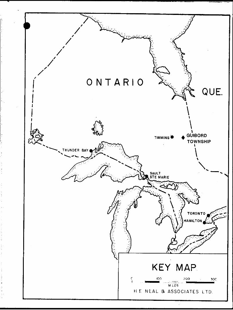
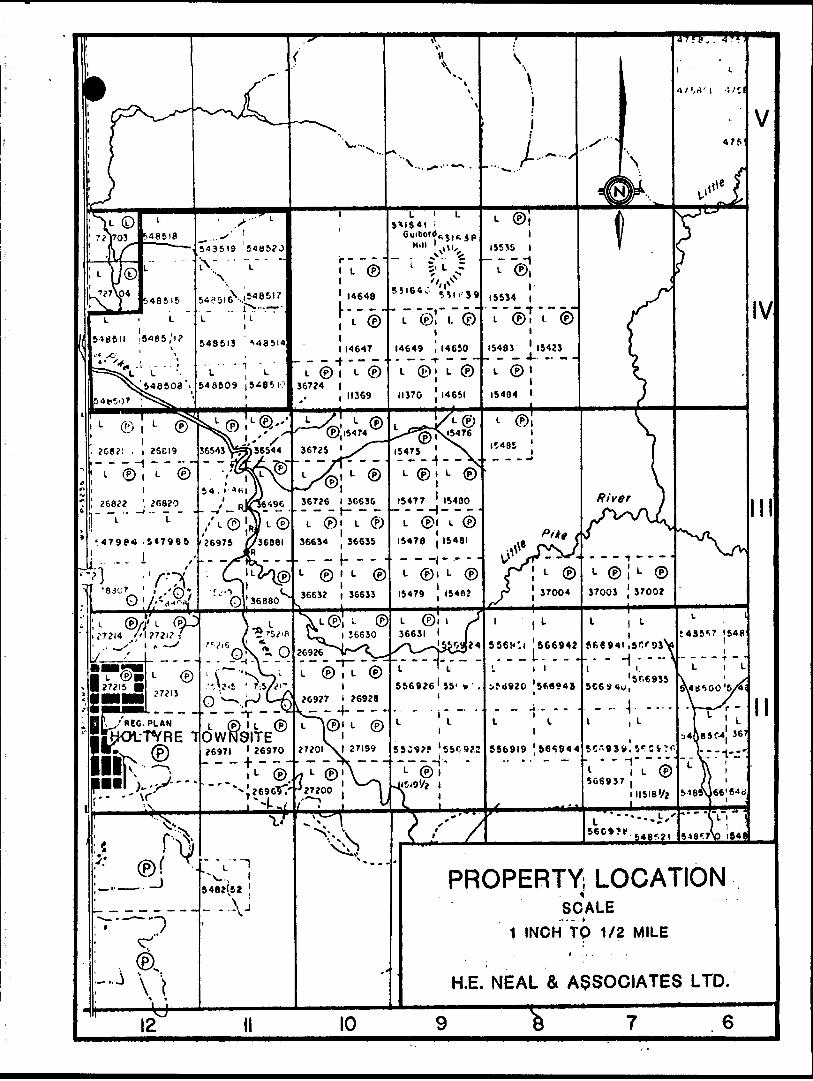
4.0 LOCATION AND ACCESS;
The fourteen mining claims are located in Guibord Township, District
of Cochrane in the Larder Lake Mining Division. All of the claims
are located Lots 11, 12, Cone. IV of Guibord Township l*s miles north
of the Holtyre Townsite. Access is by truck along Highway 572 north
from Holtyre.

L © f L (P)36724 l
11369
?C8?I . i 26CI9-l
L (P) , L (P
-.I (56694Z
.'^VlS ' 7:5/^1
- - 4- - - -
L (P) l U (POWR9ITEJ697I l 26970 956919 &6S944
PROPERTY LOCATIONSCALE
1 INCH TO 1/2 MILE
H.E. NEAL S ASSOCIATES LTD.
- 5 -
5.0 PREVIOUS WORK;
19t6 - Hislop Mines Limited drilled 4 holes across the property in
Lot 11, Concession IV. The drill holes intersected mafic
volcanics and talc chlorite schist.
1964 - Hollinger Consolidated Gold Mines drilled three holes for
a total of 2010 feet. The drill holes intersected the sed
andesite contact. Drill holes were located 480' west of
post //2 of what is now L548518.

- 6 -
6.0 LINE CUTTING;
Line cutting was done by H.E. Neal Si Associates Ltd. personnel. The
baseline was cut due east from Highway 572, 100* south of post #4 of
claim L548511. Sidelines were cut every 400' with the exception of
line 04-0. No line was cut at 0+00 due to the presence of a gas pipeline
which was expected to interfere with the geophysical surveys. A total
of 9.9 miles was cut.

- 7 -
7.0 GEOLOGY;
7.1 General Geology
The rocks in the Guibord Township area are Archean in age and belong to
the Abitibi Sub-Province of the Canadian Shield. The township and
surrounding region is underlain by a complex mix of volcanic, sedimentary
and plutonic rocks. The rocks strike generally ESE and WNW.
The Destor-Porcupine fault zone and the Pipestone fault zone are the two
major structural breaks in the area. Other shear zones occur west of
Guibord Township in Hislop Township. The Destor-Porcupine fault is the
largest of the shear zones. It crosses Guibord Township in a southeast-
northwest direction except in the southeast corner of the township where
it is east-west. The fault zone varies in dip from nearly vertical to
45 S (Prest 1951). Rocks south of the fault zone face south and are
generally steeply dipping. North of the fault zone the rocks face north
and also are steeply dipping.
The Pipestone fault zone lies 2 to 3 miles north of the Destor-Porcupine
fault. This fault strikes southeast and is thought to join up with the
Destor-Porcupine fault in Michaud Township to the east. The amount of
movement on these faults is not known.
Cross faulting is common in the area and has been noted on many outcrops
in the township. These faults usually strike NNE to north but they do
vary. Due to the amount of overburden in the area exact fault movement
is not possible. Some but not all of these faults cut across the
Destor-Porcupine fault.

- 8 -
Glacial deposits in the area range from glacial lacustrine clays and
silts which cover most of the township to outwash sands and gravels
that occur on the north east quarter of the township. The sand has been
formed by wind action into dunes. These surficial deposits are underlain
by ablation and lodgement till. The surficial deposits cover 952 of the
township and make rock correlation between outcrops difficult.
A table of formations is listed below;
CFNOX.OIC Table of Formations
RECENT AND PLEISTOCENE: Pea l; river and lake deposits; sand dunes; beach sand and gravel;varved clay; glacial outwash sand and gravel; till ground moraine).
PRECAMBRIANMATACHEWAN^?): Diabase; quartz diabase, and porphyritic phases.ALGOMAN: Granite, porphyritic fer.inite; syenite, porphyritic syenite;
feldspar porphyry, quartz-feldspar porphyry; lamprophyre; carbonate bodies, veins, etc.
BASIC INTRUSIVES: Diorite, gabbro, diabase, and their quartz-bearing equivalents;peridotite; basic intrusive breccia.
VOLCANICS AND SEDIMENTS/ Acidic volcanics, including flows and related intrusivcs; sphcroi-
SOUTHERN VOLCANICSANP SEDIMENTS:
dal and spherulitic rhyolite, coarse and fine pyroclastics ami bedded tu *
pnc ffs.
Intermediate to basic volcanics, including pillow lavas, minor spheroidal lavas, and fragmental*; lalc-chloritc schist; inter- bedded chert.
Sediments: conglomerate, greywacke, arkose, quartzite, and. argillite.
NORTHERN VOLCANICS: Dacitic to basaltic lavas and related rocks, including lavas, spheroidal livas, actinolitized volcanics, and talc-chlorite schists.
NORTHERN SEOIMKNTS: Greywacke, quartzite, argillite; minor arkose, conglomerate, and intraformational conglomerate.
from Prest 1951.
Q
7-2 Geology of the Claim Group
Only two outcrops of mafic volcanics were found in the claim group due
to thick overburden. The surficial deposit consisted of lacustine clay
and silt. Measurements taken from previous diamond drilling indicates
a thickness of 60 feet or more. Ablation till and lodgement till are
exposed on the sides of the Pike River valley and are slightly more sandy
than the lacustrine deposits. Recent surface vegetal swamp deposits
are shown on the map. The Pike River appears to be close to bedrock where
the two outcrops were located.
The following interpretation is based on the magnetic survey and observing
outcrops in surrounding properties due to the small number of outcrops
found on this property.
The assumed location of the Destor-Porcupine fault is marked on the
accompanying map.
North of the Destor-Porcupine fault zone there are two distinct zones
or rock types. The northern part of the claim group is underlain by
intermediate volcanics indicated by the low magnetic values and by
previous drilling by Hollinger. The intermediate volcanics are
underlain by mafic volcanics of basaltic composition interlayered with
probable intermediate volcanics. The examination of outcrops west of
the property indicate these are basaltic in composition and contain more

- 10 -
pyrrhotite than the andesites to the north. A certain amount of shearing
and carbonatization is in evidence in outcrops here and it is likely
to occur on the claims held by Armco. The band of intermediate volcanics
in the middle of this zone is interupted where it encounters the Destor
Porcupine fault zone.
The Destor Porcupine fault zone is marked by extremely high magnetic
values occurring as linear features surrounded by less magnetic zones.
This has been the case on other properties nearby where the fault zone has
been encountered. The linnear magnetic anomalies are likely mafic
intrusives surrounded by talc schist and talcy mafic volcanics and breccias.
Pyrite and carbonatization are common and do occur on the outcrop on
line 20E at the north side of the Pike River. An example of talcy mafic
volcanics can be seen at the south end of line 28E.
The north contact of the fault zone is discordant with the mafic volcanics
while the south contact is more concordant. A NNE trending cross fault
appears to intersect and displace all rock types north of the river between
lines 16E and 28E the fault might account for the brecciation seen on
the outcrop on the north band of the Pike River at line 20E. The area
south of the Destor Porcupine fault zone is likely underlain by mafic
volcanics.
All rock types in this claim group appear to dip steeply including the
mafic intrusives in the fault zone.

- 11 -
8.0 CONCLUSION;
The geological survey along with the magnetometer and VLF surveys aided
in'delineating structure favourable for economic mineralization. Although
few outcrops were located on the claim group the examination of other
outcrops in the immediate area was useful in obtaining an understanding
of the geology of the claim group. This understanding was necessary
for geophysical interpretation.
On the basis of the three surveys the property should be looked at in
more detail particularly south of the river close to the southern contact
of the fault zone. This area also had a strong VLF conductor. Other
areas for further work have been outlined in the other surveys.
Peter G. Atherton B.Se.
Ontario
Ministry of Natural Resources
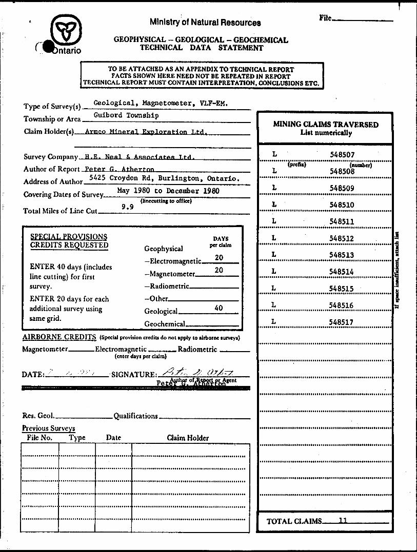
GEOPHYSICAL - GEOLOGICAL - GEOCHEMICAL TECHNICAL DATA STATEMENT
FUc.
TO BE ATTACHED AS AN APPENDIX TO TECHNICAL REPORTFACTS SHOWN HERE NEED NOT BE REPEATED IN REPORT
TECHNICAL REPORT MUST CONTAIN INTERPRETATION, CONCLUSIONS ETC.
Type of Su Township c Claim Hold
Survey Con Author of 1 Address of Covering D
Total Miles
r M Geological, Magnetometer, VLF-EM.A Guibord Township ir Area r
er(s) Armco Mineral Evnloration I,td.
npany, H -E. Neat i Afifion1afft.fi T.td.
leport Peter G. Atherton
Author
ates of Sun-
of Line Cul
25 Croydon Rd, Burlington, Ontario.May,y 3 1980 to December 1980
(linccutting to office)9.9
SPECIAL PROVISIONS CREDITS REQUESTED
ENTER 40 days (includes line cutting) for first survey.ENTER 20 days for each additional survey using same grid.
AIRBORNI Magnetome
DATE: 7
Res. Geol.
l CREDITSter
/.; X /'/" X
Previous SurveysFile No. Type
(Special provi
Electromagi (enter *
SIGW
DAYS
Geophysical p" c aim 20—Electromagnetic .20 —Magnetometer
-Radiometric-Hth-r
lion credits do not apply to airborne surveys)
netir Rariiometrirlays per claim)
iTURF,: sQfc ^ #7xfe
Qualifications
Date Claim Holder
MINING CLAIMS TRAVERSED List numerically
L 548507iprefixj '(number)
L 548508
L 548509
L 548510
L 548511
L " 548512
L 548513
L 548514
L 548515
L 548516
L 548517
i i j J 'i .
TOTAL LLAIMa ——— JJ —— —— — —— i

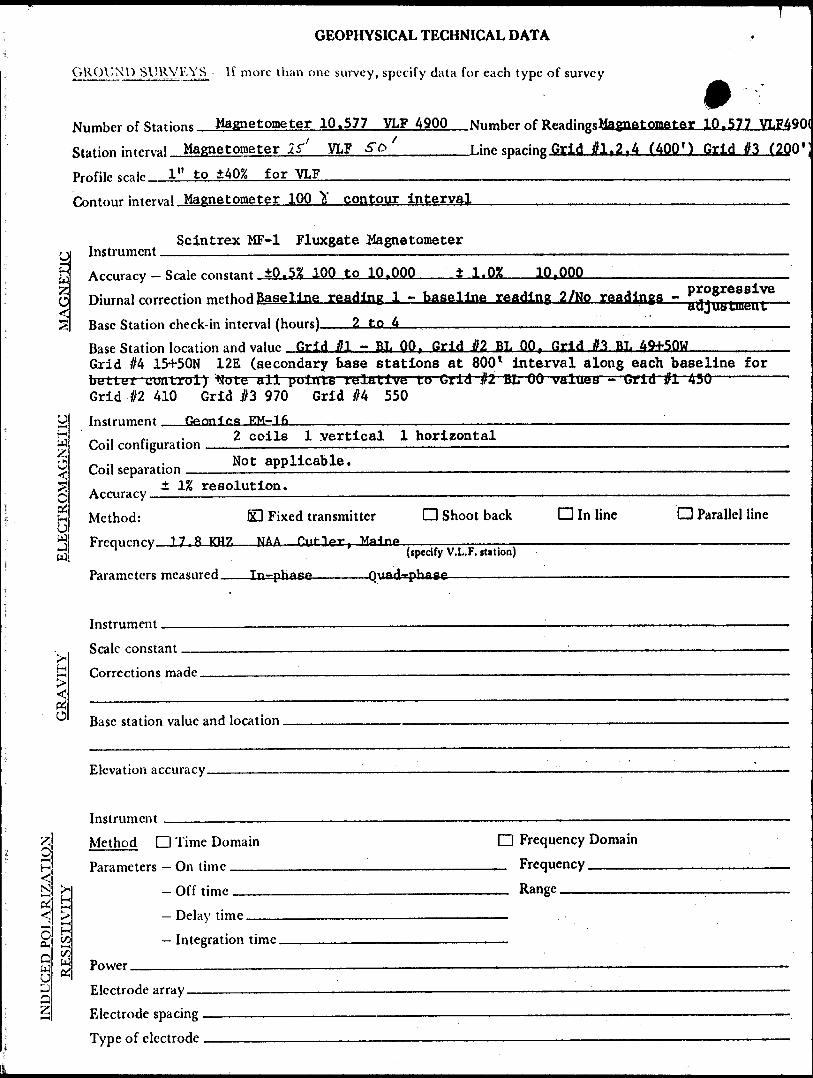
GEOPHYSICAL TECHNICAL DATA
GROUND SURVEY S — If more than one survey, specify data for each type of survey
Number of Stations Magnetometer - 2041 VLF-EM-968 Number of Readings MAG 2Q4J. Station interval MAG 25'. BL50' ; VLF-EM 50'_______Line sparing 400*-—————
Profile scale. VLF-EM - l" to 20^______________________^____Contour interval Magnetometer - 100—.—.——-.-—.^-——.-—-———-^.—..——,-..
Instrument Scintrex MF-1 Fluxgate Magnetometer——.————.———.—-—-
Zo
uH
Coil configurationO
\ H: H-4
' ^' H
COLo w
Accuracy - Scale mnctant lQ.5% from 1000 to lO.OOO't Scale ± 1.02 10.000^ scale_____.j T, progressiveDiurnal correction method Reading l Baseline minus Reading 2 Baseline/No. Readings -
Base Station check-in interval (hours)_____2 to 4_____________iBase Station location and value Baseline AE, 28E, A AE - 26Q , 320 , 210 , resper.t;tvely.
Instrument Geonics EM-16
2 coils l vertical l horizontal,, ., .. Not applicable. Coil separation ——————LL——————
± IK resolution.Accuracy.Method: 1x3 Fixed transmitter O Shoot back D In line Q Parallel linei
Hyj Frpniipnrv 17.ftKH7. M.A.A-. Tiif-lpr MafnoW
Parameters measured____In-phase____Quad-phase
Instrument.Scale constant.
Corrections made.
Base station value and location.
Elevation accuracy.
Instrument ——————————————————————————————————————'.———:——— Method D Time Domain D Frequency Domain Parameters - On time __________________________ Frequency ^^^^
-Of f time_________________________ Range ——,———..— Delay time ————————————————————————
Integration time.Power.Electrode array — Electrode spacing . Type of electrode

42A08NEC048 63.3769 GUIBORD O2O
REPORT ON
GEOPHYSICAL WORK
PERFORMED ON
ROAD PROPERTY
GUIBORD TOWNSHIP, MATHESON AREA,
LARDER LAKE MINING DIVISION - ONTARIO
FOR
ARMCO MINERAL EXPLORATION LTD.
BY
PETER G. ATHERTON B.Se.
H. E. NEAL S ASSOCIATES LTD.
TORONTO - CANADA
December, 1980
This report on the electromagnetic and magnetic survey is submitted under the special provisions dated October 16, 1967 for the credit of 40 assessment work days per claim.

1.0 SUMMARY:
A three man crew was engaged in ground geophysical surveys on the Road
Property between May 22 to June 27, 1980.
The magnetometer and VLF-EM surveys outlined two VLF conductors that
warrant further investigation. One of the conductors is associated with
a linnear magnetic body and represents a contact area. The second
conductor (conductor E) is not associated with any magnetic high and
could represent a graphitic or sulphide shear.
The magnetic survey indicated the location of the Destor-Porcupine fault
zone. The northern contact of this zone is marked by an unconformity.
More work is warranted on this property as a result of these two surveys.
- 2 -
2.0 INTRODUCTION;
The Road Claim Group was staked for Armco Mineral Exploration Ltd. in
December 1979. The group consists of 14 contiguous claims 11 of which
are being included for assessment. Crew for the work consisted of
a supervisor and two instrument operators. The claims were staked on
the basis of favourable geology. Electromagnetic and magnetic surveys
were conducted in an effort to locate and evaluate the presence of
economic minerals. Surveys were conducted on a grid with cross lines
every 400'. The surveys were completed between May 22, 1980 and June
24, 1980, as part of larger survey in Guibord Township. Various check
surveys were done throughout the summer months.
— 3 ~
3.0 THE PROPERTY;
The property consists of 14 contiguous mining claims staked in December
1979 in Guibord Township. The claims are currently held by Armco
Mineral Exploration Ltd., P.O. Box 3000, Guelph, Ontario.
The claims are listed below:
L-548507L-548508
L-548509
L-548510L-548511L-548512L-548513L-548514L-548515
L-548516L-548517L-548518 V '
L-548519'L-548520'
S*s Lot 12S*s Lot 12
Sh Lot 11
Sh Lot 118*5 Lot 12
SJg Lot 12S*s Lot 11S*s Lot 11N*5 Lot 12
N*i Lot 11Hh Lot 11NJj Lot 12
N*s Lot 11N*si Lot 11
Cone. IV Cone. IV
Cone. IV Cone. IV Cone. IV
Cone. IV Cone. IV Cone. IV Cone. IV
Cone. IV Cone. IV
Cone. IV Cone. IV Cone. IV
Claims L548518, L548519, and L548520 are not being included for credit.
9
t
4
ONTARIOQUE.
\*
\TIMMINS* 4
GUIBORDTOWNSHIP
l
\
TORONTO
HAMILTON-/'.'. -
KEY MAP100 ?00 30C
M,LES
H E NEAL S ASSOCIATES LTD
4.0 LOCATION AND ACCESS;——————————————. /
The fourteen mining claims are located in Guibord Township, District of
Cochrane in the Larder Lake Mining Division. All of the claims are
located in Lots 11, 12 Cone. IV of Guibord Township, l*i miles north of
the Holtyre Townsite. Access is by truck along Highway 572 north
from Holtyre.
l ©i L ©
L (fj l L IP9ITE
?697I ' J6970h---!---
PROPERTY; LOCATIONSCALE
1 INCH TO 1/2 MILE
H.E. NEAL 6t ASSOCIATES LTD.

- 5 -
5.0 PREVIOUS WORK;
1946 - Hislop Mines Limited drilled 4 holes across the property in
Lot 11, Concession IV. The drill holes intersected mafic
volcanics and talc chlorite schist.
1964 - Hollinger Consolidated Gold Mines drilled three holes for
a total of 2010 feet. The drill holes intersected the sed
andesite contact. Drill holes were located 480' west of
post #2 of what is now L548518.

- 6 -
6.0 GENERAL GEOLOGY;
The rocks in the Guibord Township area are Archean in age and belong to
the Abitibi Sub-province of the Superior Province. The township and
surrounding region is underlain by a complex mix of volcanics, sedimentary
and plutonic rocks. The major structural feature in the area is the
Destor-Porcupine fault zone which crosses the township in a northwest-
southeast direction. Direction and extent of movement along this fault
is not known. The fault zone varies in dip from nearly vertical to 45
South (Prest 1951).
The strata face south on the south side of the fault and face north north
of the fault. The rocks have irregularly shaped contacts but generally
strike northwest southeast.
North of the Destor-Porcupine fault zone is Pipestone fault zone. The
Pipestone Fault is another major shear that joins up with the Destor-
Porcupine Fault Zone east of Guibord Township.
Cross faulting is common in a north-north-east to north direction. Due
to the amount of overburden the extent of these faults is not known.
Glacial deposits in the area range from glacial lacustrine clay and silt
which covers most of the township to outwash sands and gravels in the
east central and northeast part of the township.
For more detailed geology of the claim group see the geological report of
the claim group.

- 7 -
7.0 GEOPHYSICS;
7.1 Magnetic Survey
The magnetic survey was carried out by M. Greer between June 8, 1980
and June 30, 1980. Weather conditions and job related activities
prevented continuous work on the grid. The survey was part of an overall
program conducted by H.E. Neal S Associates Ltd. for Armco Mineral
Exploration Ltd.
Readings were recorded at 25 feet intervals, along the side lines and
every 50 feet along the baseline. The grid consisted of an east-west
baseline with side lines at 400' intervals. No line was cut south from
00 on the baseline due to the presence of a gas pipeline, which was
expected to interfere with the magnetometer survey. Base stations were
located at 4E, 28E and 44E on the baseline.
7.1.1 Instrument and Sensitivity
The instrument used was a Fluxgate Magnetometer, Model MF-1 manufactured
by Scintrex Limited. It has an accuracy of ±0.57. from the 1000 to 10,000
gamma scale and an accuracy of ±1.07, at scales greater than 10,000 gammas.
The fluxgate magnetometer measures the strength of the vertical component
of the total magnetic field. The resulting value is given in gammas.
The magnetic field at any given station will consist of the sum of the
earth's magnetic field and the magnetic field of the bedrock at that point.

- 8 -
The magnetic field of the bedrock is dependant on the concentration of
naturally magnetic minerals in the bedrock or minerals capable of
possessing a secondary field which is induced by the earth's primary
magnetic field.
7.1.2 The Survey
The survey was conducted as described in the previous section. The base
stations were established relative to each other so that even though
different base stations were used, all stations recorded on the grid
could be plotted relative to each other. Base stations were read four
times daily. In addition to the four base stations all other baseline
stations were taken relative to the base stations to eliminate the need
for more frequent checks.
Due to fluctuations in the earth's magnetic field it is necessary to take
frequent base station readings. Any apparent changes in the magnetic
intensity that occur during the time interval between baseline checks is
then applied as a progressive adjustment to the readings taken during that
period of time.
The contoured results of the magnetic survey aid in the determination of
strike, dip, location and shape of a magnetic body.
- 9 -
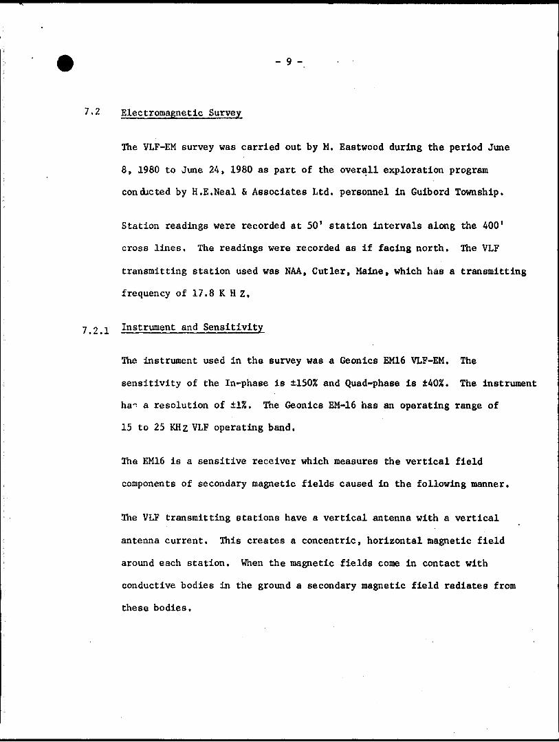
7.2 Electromagnetic Survey
The VLF-EM survey was carried out by M. Eastwood during the period June
8, 1980 to June 24, 1980 as part of the overall exploration program
conducted by H.E.Neal S Associates Ltd. personnel in Guibord Township.
Station readings were recorded at 50' station intervals along the 400'
cross lines. The readings were recorded as if facing north. The VLF
transmitting station used was NAA, Cutler, Maine, which has a transmitting
frequency of 17.8 K H Z.
7.2.1 Instrument and Sensitivity
The instrument used in the survey was a Geonics EM16 VLF-EM. The
sensitivity of the In-phase is ±15056 and Quad-phase is ±405!. The instrument
ha^ a resolution of ±1K. The Geonics EM-16 has an operating range of
15 to 25 KHz VLF operating band.
The EM16 is a sensitive receiver which measures the vertical field
components of secondary magnetic fields caused in the following manner.
The VLF transmitting stations have a vertical antenna with a vertical
antenna current. This creates a concentric, horizontal magnetic field
around each station. When the magnetic fields come in contact with
conductive bodies in the ground a secondary magnetic field radiates from
these bodies.
-10 -
The receiver has two receiving coils with one coil having a vertical axis
and the other a horizontal axis. The signal from the vertical axis coil is
minimized by tilting the instrument which measures the vertical real
component as a percentage. The remaining signal is balanced out by a
measured percentage of a signal from the horizontal coil which gives an
accurate measure of the quadrature vertical signal. The measured values
are relative only.
The VLF station N.A.A. Cutler, Maine was chosen because it is in line
with the strike of the rocks in the area. The results of a survey when
plotted as a profile show the location of various conductors in the ground.

- 11 -
8.0 RESULTS:
8.1 Magnetic Survey
The magnetic area outlined three distinct magnetic zones. The northern
most magnetic area (Zone A) is characterized by low magnetic values. These
values are fairly consistent north of the baseline with the contact between
it and Zone B occurring between 28E on the baseline and 9+258 on line 52E.
Examination of outcrops nearby and drill hole logs in the area show the
bedrock to be andesite.
The government geological map for the area shows the southern contact
of a large sediment band in the cutting through the property. The magnetic
information does not show this contact as it did not extend far enough
north. The middle zone (Zone B) is delinneated by higher magnetics than
in Zone A. Bedrock in this zone ±e most likely massive mafic lavas.
Examination of nearby outcrops that are an extension of this zone show
this to be the case. Dips appear to be north. The magnetic low occurring,
in the centre of the zone is likely to be intermediate volcanics.
The contact between Zone B and Zone C appears to be unconformible
indicating Zone C to be the Destor-Porcupine Fault Zone. The extremely
high magnetic bodies alternate with lower magnetic bodies. The magnetic
body between lines 20E and 28E on the north bank of the Pike River is
associated with mafic breccias. The other linear magnetic bodies are
probably mafic intrusives surrounded by talc schist. These rock types
are common in the JDestor-Porcupine Pault Zone in the area. A fault appears
to intersect both zones B and C in the area of lines 20E and 24E. The
fault strikes NE-SW.
- 12 -
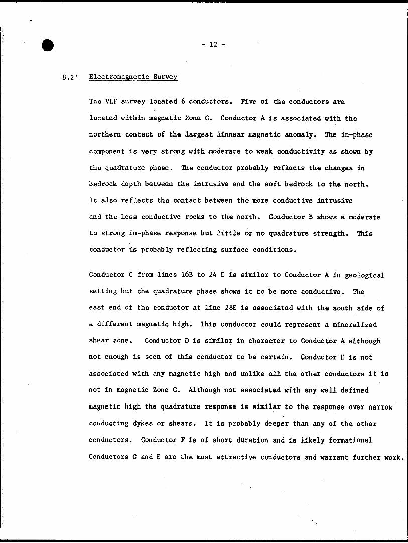
8.2' Electromagnetic Survey
The VLF survey located 6 conductors. Five of the conductors are
located within magnetic Zone C. Conductor A is associated with the
northern contact of the largest linnear magnetic anomaly. The in-phase
component is very strong with moderate to weak conductivity as shown by
the quadrature phase. The conductor probably reflects the changes in
bedrock depth between the intrusive and the soft bedrock to the north.
It also reflects the contact between the more conductive intrusive
and the less conductive rocks to the north. Conductor B shows a moderate
to strong in-phase response but little or no quadrature strength. This
conductor is probably reflecting surface conditions.
Conductor C from lines 16E to 24 E is similar to Conductor A in geological
setting but the quadrature phase shows it to be more conductive. The
east end of the conductor at line 28E is associated with the south side of
a different magnetic high. This conductor could represent a mineralized
shear zone. Conductor D is similar in character to Conductor A although
not enough is seen of this conductor to be certain. Conductor E is not
associated with any magnetic high and unlike all the other conductors it is
not in magnetic Zone C. Although not associated with any well defined
magnetic high the quadrature response is similar to the response over narrow
coiiducting dykes or shears. It is probably deeper than any of the other
conductors. Conductor F is of short duration and is likely formational
Conductors C and E are the most attractive conductors and warrant further work.

- 13 -
9.0 CONCLUSION:
Both the VLF-EM and the magnetic survey were useful in defining geological
structure in the area. The VLF survey outlined two conductors that
warrant further work. Conductor C is associated with a magnetic high
which appears to be faulted in the east end, between line 24E and 28E.
The shape of the conductor indicates it is at depth and not surficial.
The conductor warrants more work at a closer line interval.
Conductor E is not associated with any particular magnetic high although
it is in a zone of higher magnetics. This conductor could be the
southern contact of the Destor-Porcupine fault. At any rate the conductor
shape shows it to be at depth and more detailed work should be carried
out over the conductor.
Peter G. Atherton B.Se.
ntario
Ministry of Natural Resources
GEOPHYSICAL - GEOLOGICAL - GEOCHEMICAL TECHNICAL DATA STATEMENT
File.
TO BE ATTACHED AS AN APPENDIX TO TECHNICAL REPORTFACTS SHOWN HERE NEED NOT BE REPEATED IN REPORT
TECHNICAL REPORT MUST CONTAIN INTERPRETATION, CONCLUSIONS ETC.
Geological, Magnetometer, VLF-EM.Type of Survey(s).
Township or Area.
Claim Holder(s) Armco Mineral Exploration Ltd.
Guibord Township
Survey Company H. E. Npal f, T.f-d .
Author of Report Peter R .Address of Author 5 425 Croydon Rd * Burlington, Ontario.n . T, . t c May 1980 to December 1980 Covering Dates of Survey- J
Total Miles of Line Cut_ 9.9(linecutting to office)
SPECIAL PROVISION? CREDITS REQUESTED
ENTER 40 days (includes line cutting) for first survey.ENTER 20 days for each additional survey using same grid.
Geophysical
—Electromagnetic.—Magnetometer^.—Radiometric——
DAYS per claim
2020
40
AIRBORNE CREDITS (Special provision credit* do not apply to airborne turveyi)
Magnetometer. .Electromagnetic. . Radiometric
DATE:.
(enter dayi per claim)
SIGNATURE:.
Res. Geol.. .Qualifications.Previous Surveys
File No. Type Date Claim Holder
MINING CLAIMS TRAVERSED List numerically
L
L
548507(number)
548508
548509
548510
548511
548512
548513
548514
548515
548516
548517
TOTAL CLAIMS LL

GEOPHYSICAL TECHNICAL DATA
JND SURVEYS — If more than one survey, specify data for each type of survey1
Number of Rtatinnc Magnetometer - 20A1 VLF-EM-968 Nnmhpr of Readings MAfl 2Q&1 Station int^l MAG 25*. BL50' ; VLF-EM 50*______Line sparing ^00*---——- Profile *™^ VLF-EM - l" to 20%_______________________^______Contour interval Magnetometer - 100——————————————————————————.
Instrument Scintrex MF-1 Fluxgate Magnetometer^—————...——.-———.
a
O
,, ,. f. .. 2 coils l vertical l horizontal Coil configuration — —f*
sS BID
O
Accuracy — Scale constant AO.5% from 1000 to 1Q,Q001 Scale ± 1.01 10 tOQO^ scale Diurnal correction method Reading l Baseline minus Reading 2 Baseline /No. Readings -j Base Station check-in interval (hours)—————2 to k___________________;-—-——-—.
progressive
Base Station location and value Baseline 4E, 28E, 4AE - 26Q , 320 , 210 , respectively.
Instrument Geonics EM-16
0 ., t . Not applicable. Coil separation ______LL——————± ^ resolution.. Accuracy
Method: E Fixed transmitter D Shoot back Q In line O Parallel line T7 T ft KH7f N.AiAii Cutler Main?
Parameters measured ____ In-rHase ____ Quad-pha
InstrumentScale constantCorrections made.
Base station value and location,
Elevation accuracy.
Instrument ————————————————————————————————————————————— Method D Time Domain D Frequency Domain Parameters - On time __________________________ Frequency —^^-.
-Offtime________________________ Range ———————— Delay time ——————————————————————————
g wPower.
— Integration time.
Electrode array — Electrode spacing . Type of electrode

42Ae8NEee40 63.3789 GUIBORD 030
n\ j^
REPORT ON
LINE CUTTING AND GEOLOGICAL SURVEY
PERFORMED ON
MAIN GROUP PROPERTY
GUIBORD TOWNSHIP
LARDER LAKE MINING DIVISION
MATHESON AREA - ONTARIO
FOR
ARMCO MINERAL EXPLORATION LTD.
BY
PETER G. ATHERTON B.Se.
H. E. NEAL 6. ASSOCIATES LTD.
TORONTO - CANADA
December, 1980
This report on the electromagnetic and magnetic survey is submitted under the special provisions dated October 16, 1967 for the credit of 40 assessment work days per claim.

1.0 SUMMARY:
The geological survey was conducted by H.E. Neal tt Associates personnel
between July 6, 1980 and October 1980. The survey was conducted over
grids cut in the bush by contractors and H.E. Neal S Associates
personnel.
The survey located the Destor Porcupine fault zone on the property
as well as two other shear zones that appear to be favourable zones
for gold mineralization. In addition to the above, numerous areas of
carbonatization were located which should be sampled.
The resulting interpretation shows the area is mainly underlain by
intermediate to basic volcanics with some lensitic bands of sediments.
A large band of sediments composed of greywacke, argillite and con
glomerate was also located which has quartz carbonate veins and some
sulphide mineralization. The major Intrusive rocks in the area arei
gabbro, granite and syenite, as well as late diabase dykes.
The interpretation showed the property to have good potential for gold
mineralization.
- 2 -
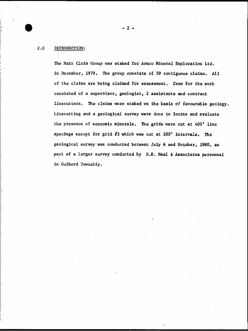
2.0 INTRODUCTION;
The Main Claim Group was staked for Armco Mineral Exploration Ltd.
in December, 1979. The group consists of 59 contiguous claims. All
of the claims are being claimed for assessment. Crew for the work
consisted of a supervisor, geologist, 2 assistants and contract
linecutters. The claims were staked on the basis of favourable geology.
Linecutting and a geological survey were done to locate and evaluate
the presence of economic minerals. The grids were cut at 400* line
spacings except for grid #3 which was cut at 200* intervals. The
geological survey was conducted between July 6 and October, 1980, as
part of a larger survey conducted by H.E. Neal i Associates personnel
in Guibord Township.
- 3 -
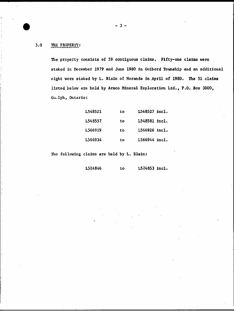
3.0 THE PROPERTY;
The property consists of 59 contiguous claims. Fifty-one claims were
staked in December 1979 and June 1980 in Guibord Township and an additional
eight were staked by L. Blain of Noranda in .April of 1980. The 51 claims
listed below are held by Armco Mineral Exploration Ltd., P.O. Box 3000,
Guelph, Ontario:
L548521 to L548527 incl.
L548557 to L548581 incl.
L566919 to L566926 incl.
L566934 to L566944 incl.
The following claims are held by L. Blain:
L524846 to L524853 incl.

/
*
ONTARIOQUE.
t
\*
\TIMMINS'* 4
iGUIBORDTOWNSHIP
l
\
TORONTO WT- ^,^-r
HAMILTON ^.' -
KEY MAP100 ?00 30C
M.LES
H E NEAL a ASSOCIATES LTD
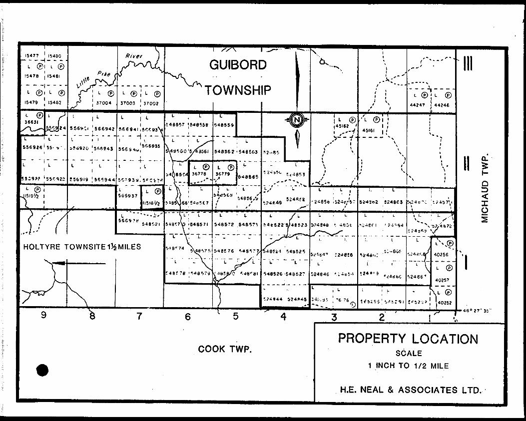
15477 ' 15480
GUIBORD
TOWNSHIP
HOLTYRE TOWNSITEI^MILES
PROPERTY LOCATIONCOOK TWP. SCALE
1 INCH TO 1/2 MILE
H.E. MEAL 8c ASSOCIATES LTD.

- 4 -
4.0 LOCATION AND ACCESS;
The fifty-nine claims are located in Guibord Township, District of
Cochrane in the Larder Lake Mining Division. All of the claims are
in lots 3 to 10 incl., Concessions I and li of Guibord Tovmship. The
west side of the claim group is l*s miles east of the Holtyre Townsite.
Access is by all terrain vehicle along a trail going east from Holtyre
along the boundary between Concessions l and II.
- 5 -
5.0 PREVIOUS WORK;
1947 - Gui For Gold Mines Limited drilled 720 feet in what is now
Claim L566941.
1947 - Weldon Gold Mines Limited conducted a magnetometer survey
over the area now covered by grid #2.
1951 - Dominion Gulf drilled 6 holes for a total of 3,047 feet in
the western end of grid #4.
1964 - Hollinger Consolidated Gold Mines conducted a magnetometer
survey over the area covered by grid #3 and part of grid //4.
1965-66 - Six drill holes by Hollinger for a total of 4419 feet were
drilled.
1974 - Noranda Exploration Company Limited conducted a magnetometer
and electromagnetic survey over the area covered by grid #3.
- 6 -
6.0 LINE CUTTING;
Grids l, 2 and 4 were cut by professional linecutters supplied by
G. Potter of Swastika, Ontario. Lines were cut at 400 foot intervals
on these grids.
Grid if3 was cut by H.E. Neal tt Associates personnel and had 200' lines
spacings. Lines 18, 22, 26, 30, 34, 38, 42 and 46W on grid #1 were
cut by H.E. Neal S Associates Ltd. A total of 54 miles was cut.
- 7 -
7.0 GEOLOGY;
7.1 General Geology,
The rocks in the Guibord Township area are Archean in age and belong to
the Abitibi Sub-Province of the Superior Province. The township and
surrounding region is underlain by a complex mix of volcanics,
sedimentary and plutonic rocks.
The major structural feature in the area is the Destor-Porcupine fault
zone which crosses the township in a northwest-southeast direction.
The direction and extent of movement along the fault is not known.
The fault zone varies in dip from nearly vertical to 45 south
(Prest 1951).
The strata face south on the south side of the fault and north on the
north side of the fault. The rocks have irregularly shaped contacts
but generally strike northwest-southeast.
The second major structural feature is the Pipestone fault zone which
lies north of Destor-Porcupine fault. The Pipestone fault joins up with
the Destor-Porcupine fault east of Guibord Township.
Cross faulting is common in a NNE to north direction. Due to the amount
of overburden the extent of these faults is not known.
Glacial deposits in the area range from glacial lacustrine clay and silt

CKXO2O1C Table of Formations
RECENT AND PLEISTOCENE: IVat; river and lake deposits; sand dunes; Iwach sand and gravel;varved clay; glacial outwash sand and gravel; till groundmoraine).
rur.CAMBRIAXMATACHEWAN(?): Diabase; quartz diabase, and porphyritic phases.ALGOMAN: Granite, gxirphyritic granite; syenite, porphyritic syenite;
feldspar porphyry, quam-feldspar porphyry; lamprophyre; carbonate bodies, veins, etc.
BASIC INTRUSIVE?: Diorite, gabbro, diabase, and their quartz-bearing equivalents;peridotite; basic intrusive breccia.
VOLCANICS A\K SEDIMENTS•Acidic volcanics, iiirhnliiiR flows and related intrusive*; sphcroi-
SOUTIIKRX VOLCANICS ASH Si:i)tut:sTs:
dal and snherulitic rli)olitc, coarse and fine pyroclastics and bedded tuffs.
Intermediate lo basic volcanics, including pillow lavas, minorspheroidal lavas, anil fr.itiiuentals; talc-citlorilc KCJiist; inter bedded chert.
Sediments: conglomerate, greywacke, arkose, quartzite, and argillite.
NOKTIIKKN \'UI.CANICS: Dacitic to basaltic luvas and related rocks, including lavas, spheroidal lavas, aclinoliti/ed volcanics, and talc-chlorite
NORTIIKKS SHUMKNTS: Greywacke, quartzite. ar^Mlite; minor arkose, conglomerate, and imr.iforiiKuion.il
from Prest 1951.
- 8 -
which covers most of the township to outwash sand and gravel in the
east-central and northeast part of the township. These surficial
deposits are underlain by ablation and lodgement till which tend to
be more sandy and less sorted.
7.2 Geology of the Claim Group
The interpretation is based on outcrop evidence from the survey and
from magnetic interpretation where no outcrop was located.
7.2.1 Sediments
The sediments in the claim group consist of greywacke, conglomerate,
argillite and arkose. These rocks most frequently occur as thin
irregular bands and lenses between volcanic and intrusive rocks. Only
one band of sedimentary rocks can be traced with confidence from the
east end of the property to the north part of grid #1, line 24W. In
the west this band of sediment is predominantly greywacke and argillite
with very little conglomerate. This zone is highly sheared. To the
east the rocks are mostly composed of greywacke, arkose and conglomerate.
These rocks are not as sheared probably due to the rock being more
competent because of the presence of more clastic type rocks. The grey
wacke is massive to thinly bedded in the east end and relatively
undisturbed since primary sedimentary features are still existent. The
rock is buff grey on the weathered surface and dark grey to black on the
fresh surface.

- 9 -
The argillite is seen only at the west end of the sedimentary band and it
is a black shaley rock containing much pyrite.
The arkose occurs only in the east end and is pink on the fresh surface to
buff coloured when weathered. Bedding is generally massive although
argillaceous layers show some shearing and are thinly bedded.
The conglomerate is a polymictic rock with clasts up to 6". The clasts are
elongate to round and are in a greywacke matrix. Clasts are composed of
volcanic, granitic, gabbroic and sedimentary rocks. The elongation is in
the direction of strike and since shearing is in this direction may be
a result of this.
The band of sediments is 500* wide in the west and reaches widths of
1200' in the east.
Pyrite is the most common sulphide present with some chalcopyrite
The band has much quartz/carbonate veining throughout. These veins
range in size from .5 inches to one foot with some sulphide mineralization
along the borders.
7.2.2 Intermediate to Basic Lavas
These are the most common rock types in the claim group. They range from
andesitic to gabbroic composition. The pillowed variety is relatively
thin (20* to SO 1 ) compared to the more massive gabbroic lavas. Pillows
show tops facing south in all cases where the rock type was observed on

- 10 -
the property and average about 1.5 to 2 feet in diameter.
The massive gabbroic lava is fine to medium grained and shows considerable
thickness. These rocks are difficult to distinguish from the gabbro
intrusives. The major difference is grain size and the gabbros are
more magnetic containing both magnetite and pyrrhotite. The gabbroic
lavas are less magnetic or non-magnetic containing mostly pyrite as an
accessory mineral. These rocks are relatively underformed except south
of the baseline on grid M where they have been sheared with extensive
quartz carbonate veining occurring. Where shearing has occurred between
lines 16W and 40W north of the baseline some of the adjacent intermediate
volcanics have been carbonatized. The volcanics have been extensively
altered in the vicinity of the Destor-Porcupine fault and are altered
to talc chlorite schist and carbonate rock.
7.2.3 Rhyolite and Spheroidal Rhyolite
Rhyolite occurs on the property in outcrop on grid if l, north of the
baseline between lines 20W and 40W. Magnetometer data indicates that the
unit is faulted out between two gabbro intrusives by line 12W. The
rhyolite is spherulitic in places and sheared. Quartz carbonate veining is
common. Pyrite and chalcopyrite are disseminated throughout the rock
type.
The spheroidal lava is green in colour and occurs as a discontinuous band
in the shear zone. The rock contains glassy pea size spheres. The unit
is more sheared than the rhyolite and carbonatization is extensive.
\
- 11 -
The band of spheroidal lava in the large outcrop area at the south end of
line 4W grid //l is relatively underformed and has little veining or
fracturing.
7.2.4 Gabbro
Most of this rock type is seen on the west end of grid #1 in the large
outcrop area and south where large numbers of outcrop occur. These
correspond to magnetic highs. To the east shearing and the presence of
pyrrhotite in the mafic lavas cause linear magnetic highs to occur in the
lavas and the magnetic distinction is not as clear. The gabbro is a medium
to coarse grained intrusive rock containing pyroxene, hornblende and
plagioclase, pyrite and pyrrhotite. The fresh surface has a dark green to
black appearance while weathered surfaces are a brown to grey colour.
These rocks are nearly indistinguishable from the gabbroic lavas and unless
actually seen in outcrop they are not plotted as gabbro on the map.
7.2.5 Granitic Rocks
The granite and granite porphyry occur in two places on the claim group.
The outcrop at 18N line 12W grid //l appears to be a small localised plug.
It is a quartz porphyry with pink feldspar. It is a small outcrop and
likely intruded into a zone of weakness along the shear.
The second outcrop is located from 8W to west of 12W on grid if3 south
of the baseline. The outcrop is megacrystic granite consisting of coarse
grained quartz and feldspar.
- 12 -
Syenite is not seen in outcrop on the property but does occur on
NW^i 5*5 Lot 5 Con. 2 as small intrusive bodies south of the Des tor-
Porcupine fault. Drilling by Hollinger in 1964 show it to occur north
of the Destor-Porcupine fault. This coincides with a magnetic low and
it can be assumed that larger bodies of syenite do occur on the claim
block.
7.2.6 Diabase
This rock type occurs as numerous small dykes throughout the claim block.
The trend of these dykes is generally north-south or northwest-southeast.
Exceptions occur where the dykes intersect shear zones or other zones of
weakness. The dykes tend to parallel these zones for short distances
before cutting across. These are the youngest rock types in the area
and were seen cutting all other rock types. All of the diabase dykes
in the claim group are fine to medium grained and are easily recognized
by the blocky jointing.
7.2.7 Carbonate Rock
This rock type occurs only on grid #3 where three small outcrops are
located. The rock is a result of carbonate alteration of the bedrock
within the Destor-Porcupine. The unit is not continuous. Two varieties
exist in the claim group.
The first variety is a green, micaceous unit that is soft and contains
some pyrite. Chlorite is common. The second variety is reddish, hard
- 13 -
and siliceous and contains abundant pyrite and chalcopyrite. All rock
types in the vicinity have been carbonatized in the area of the fault
zone to varying degrees.
7.2.8 Surficial Geology
Pleistocene silts and clays overlay about 9(^ of the claim block.
The silt and clay was only seen in section along the Little Pike River
and is about 5 feet thick. Sand and gravel underlay most of the clay.
Organic swamp deposits occur everywhere on the claim block due to low
relief and resulting poor drainage.
7.3. Structure
The rock, types where seen in the claim group are without exception
facing south. The rocks strike in a northwest-southeast direction except
to the east where the strike changes to due east-west. The Destor-Porcupine
fault is well marked in outcrop and geophysics and trend south-east.
Other shears parallel to strike are found in outcrop north of the baseline
in grid //l. The northern most shear is composed of a band of sediments
which likely formed a zone of incompetent rocks compressed between more
competent gabbro and volcanics. Pyrite and other sulphides are common
in this zone. The shear can be traced the length of the property but the
amount of shearing lessens to the east.
The southern shear appears to be a zone of less competent volcanics between
two gabbro intrusives. This also is parallel to strike but has a much
- 14 -
shorter duration. It appears to be faulted out around 16W on grid 1.
This is also a zone with abundant pyrite and chalcopyrite.
Cross cutting faults in a northerly direction were seen in outcrop in a
few places but generally are inferred from the magnetic survey. Where
seen in outcrop they are rusty zones a few feet to about 20 feet wide
often accompanied by a breccia zone. Movement appears to be right
handed. The location of all of these faults is shown on the
accompanying maps.
- 15 -
8.0 CONCLUSION:
The geological survey located the Destor-Porcupine fault zone as well
as two secondary shear zones running parallel to it. As shear zones
are favourable zones for economic minerals more work should be conducted
in these areas. The survey also located areas of quartz-carbonate
veining which should be sampled.
As well as providing the above information the survey and resulting
interpretation gave a reasonable explanation for some of the magnetic
anomalies and VLF conductors. The results were a tentative geological
map for the claim group.
l Peter G. Atherton B.Se.t
Ontario
Ministry of Natural Resources
GEOPHYSICAL - GEOLOGICAL - GEOCHEMICAL TECHNICAL DATA STATEMENT
File.
TO BE ATTACHED AS AN APPENDIX TO TECHNICAL REPORTFACTS SHOWN HERE NEED NOT BE REPEATED IN REPORT
TECHNICAL REPORT MUST CONTAIN INTERPRETATION, CONCLUSIONS ETC.
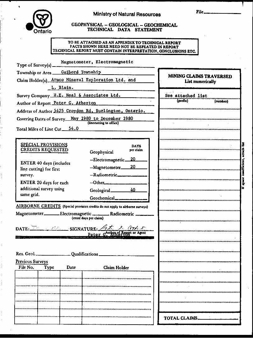
Type of Survey(s).Magnetometer, Electromagnetic
Township or Area Guibord TownshipClaim Holder(s) Armco Mineral Exploration Ltd. and
L. Blain.H.E. Neal S Associates Ltd.
Author of Report Peter G. AthertonAddress of Author 5425 Crovdon Rd. Burlington, Ontario. Covering Dates of Survey May 1980 to December 1980
(linecutting to office)
Total Miles of Line fint 54.0—^-—.—--—--.--^———--
SPECIAL PROVISIONS CREDITS REQUESTED
ENTER 40 days (includes line cutting) for first survey.
ENTER 20 days for each additional survey using same grid.
Geophysical—Electromagnetic—20.—Magnetometer.——2Q—Radiometric——————Other———————-
DAYS per claim
Geological.Geochemical.
AIRBORNE CREDITS (Special provision credits do not apply to airborne turveys)
Magnetometer. .Electromagnetic. . Radiometric
DATE:.
(enter days per claim)
SIGNATURE: Peter
Res. Geol.. .Qualifications.Previous Surveys
File No. Type Date Claim Holder
MINING CLAIMS TRAVERSEDLUt numerically
See attached list(number)
• OTl
TOTAL CLAIMS.
GEOPHYSICAL TECHNICAL DATA
GROUND SURVEYS — I f more than one survey, specify data for each type of survey"^
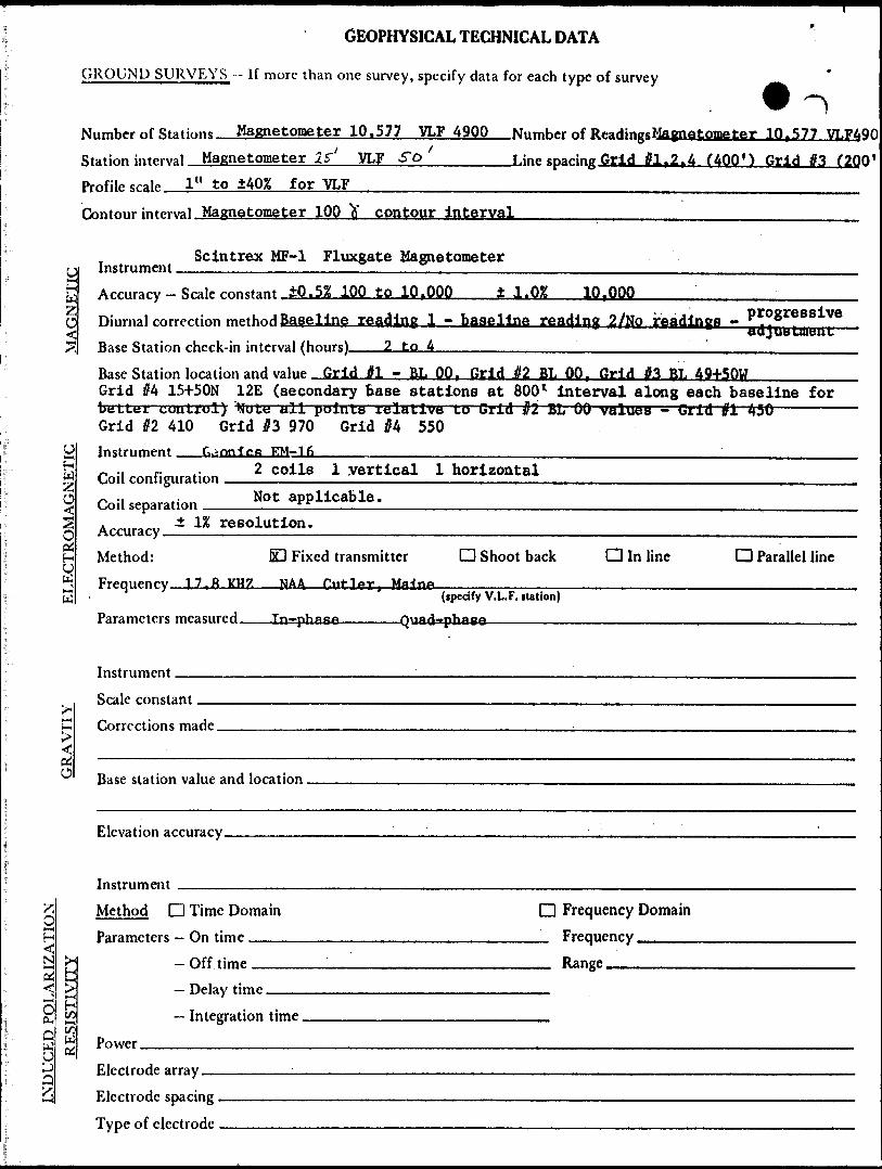
Niimhpr of Stations Magnetome ter 10.577 VLF 4900 Nnmher of Rf-aHinasMaimetometer 10.577 VLF4
INDUCED POLARIZATION
UH WC
16
1H U
f-H
OdO
i*
^ h*—V.
X
Station interval Magnetometer 25"' VLF SO L ine sparing Grid tfl f 2 t4 (400') Grid
Profile scale 1" to ±40% f or VLF
Contour interval Magnetometer 10Q y contour interval
Scintrex MF-1 Fluxgate MagnetometerInstrument
Armory Scalp constant ±0.5% 100 tO 10.000 ± l .OX 10 f OOO
ninrnal correction method Baseline reading 1 - baseline reading 27K[o readings - ..* 8
#3 (20
s i vettu J vat tuitsu u
Base Station ch^rk-in interval (hours). ..,2 to4
Race Station loration and value Grid M - PL 00 r Grld ^2 BL 00 f Grid #3 BL 49+50WGrid #4 15+50N 12E (secondary base stations at 800 l Interval along each baselinebetter control) Note all points relative to Grid j?2 BL 00 values - Grid til 450 —— Grid #2 410 Grid jP3 970 Grid #4 550Instrument f^onJcfi EM-16^ ., r. ,. 2 coils 1 vertical 1 horizontalCoil Configuration0 .. . Not applicable.Toil separation rr
A™,,^ i " resolution.
Method: O Fixed transmitter Q Shoot back Q In line CD Parallel Frequency 17.8 KHZ NAA C"r ]|or. Maine
1 (ipecify V.L.F. nation) Pa ramblers measured . In-pbise Quad-phase
Instrument
Srale constant
f-orrrrtjons maHe
Basf station value and location , . ,,
Elevation accuracy.,. . . ..™. . , , , — . — ... — .... , .... ,
Instrument ,. ,.... ,. , . . —— ..,....,.,. —— ,.,Method D Time Domain D Frequency DomainParameters — On time . ,, ., Frequency
- Off tim^ Range
— Delay time .. ..,....... -,..,.. .,......- Integration time
Power
Electrode array. . — ...,.. . .
Electrode spacing .Tvne of electrode , ....., — — ...,. —, -
for
line

MINING CLAIMS TRAVERSED
L-548521 L-548522 L-548523 L-548524 L-548525 L-548526 L-548527
L-548557 L-548558 L-548559 L-548560 L-548561 L-548562 L-548563 L-548564 L-548565 L-548566 L-548567 L-548568 L-548569 L-548570 L-548571 L-548572 L-548573 L-548574 L-548575 L-548576 L-548577 L-548578 L-548579 L-548580 L-548581
L-566919 L-566920 L-566921 L-566922 L-566923 L-566924 L-566925 L-566926
L-566934 L-566935 L-566936 L-566937 L-566938 L-566939 L-566940 L-566941 L-566942 L-566943 L-566944
L-524846 L-524847 L-524848 L-524849 L-524850 L-524851 L-524852 L-524853

42A08NE0040 63.3789 GUIBORD 040
/ 7 X/-* /~ -
^' C^- ~" Q TREPORT ON
GEOPHYSICAL WORK
PERFORMED ON
MAIN GROUP PROPERTY
GUIBORD TOWNSHIP
LARDER LAKE MINING DIVISION
MATHESON AREA - ONTARIO
FOR
ARMCO MINERAL EXPLORATION LTD.
BY
PETER G. ATHERTON B.Se.
H. E. NEAL 6 ASSOCIATES LTD.
TORONTO - CANADA
December, 1980
This report on the electromagnetic and magnetic survey is submitted under the special provisions dated October 16, 1967 for the credit of 40 assessment work days per claim.
1.0 SUMMARY:
A four man crew was engaged in geophysical surveys on the Main Property
in Guibord Township between March 17 and October 15, 1980.
Several VLF-EM conductors were located during the survey. Seven con
ductors were considered to be worth following up. They are describeds ~
in the conclusions.
The magnetometer survey was useful in outlining geological structure
as well as providing an explanation for some of the VLF conductors.
The survey located the presence of a geological complex area on grid //l
between lines 16W and 36W which was found to be a shear zone of
rhyolite and spheroidal lavas. The magnetic survey also indicated the
probable location of the Destor-Porcupine fault zone.
These conductors and magnetic anomalous zones will be explored further
in 1981 in a more detailed survey.

- 2 -
2.0 INTRODUCTION!
The Main Claim Group was staked for Armco Mineral Exploration Ltd.
in December 1979. The group consists of 59 contiguous claims all of
which are being claimed for assessment. Crew for the work consisted
of a supervisor, one geologist and two instrument operators. The
claims were staked on the basis of favourable geology. Electromagnetic
and magnetic surveys were conducted in an effort to locate and evaluate
the presence of economic minerals. Surveys were conducted on a grid
with cross lines every 400' except grid #3 where cross lines were every
200*. The surveys were completed between March, 1980 and October,
1980 as part of larger survey in Guibord Township. Various check surveys
were done throughout the summer months. Claim L548567 is being
submitted for magnetometer survey only.
- 3 -
3.0 THE PROPERTY;
The property consists of 59 contiguous claims. Fifty-one claims were
staked in December, 1979 and June, 1980 in Guibord Township and an
additional eight were staked by L. Blain of Noranda in April of 1980.
The 51 claims listed below are held by Armco Mineral Exploration Ltd.,
P.O. Box 3000, Guelph, Ontario:
L548521 to L548527 incl.
L548557 to L548581 incl.
L566919 to L566926 incl.
L566934 to L566944 incl.
The following claims are held by L. Blain:
L524846 to L524853 incl.

t
4
ONTARIOQUE.
TORONTO
HAMILTON ^^i \
KEY MAP100 POO 30C
M.LFS
H E NEAL a ASSOCIATES LTD
- 4 -
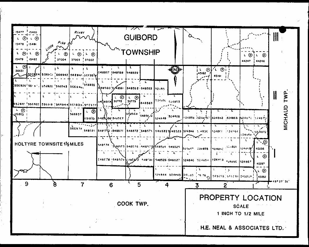
4.0 LOCATION AND ACCESS;
The fifty-nine claims are located in Guibord Township, District of
Cochrane in the Larder Lake Mining Division. All of.the claims are in
lots 3 to 10 incl., Concessions I and II of Guibord Township. The
west side of the claim group is 1*5 miles east of the Holtyre Townsite.
Access is by all terrain vehicle along a trail going east from Holtyre
along the boundary between Concessions I and II.
I54T7 ' 15480- - - H- - -
L (P)l L (P GUIBORD
TOWNSHIP
556JO ' 566942l *' T ' - l i l.—'— J . . - - - - x
HOLTYRE TOWNSITEI^MILES
PROPERTY LOCATIONCOOK TWP. SCALE
1 INCH TO 1/2 MILE
H.E. MEAL 6t ASSOCIATES LTD.

- 5 -
5.0 PREVIOUS WORK;
1947 - Gui For Gold Mines Limited drilled 720 feet in what is now
Claim L566941.
1947 - Weldon Gold Mines Limited conducted a magnetometer survey
over the area now covered by grid #2.
1951 - Dominion Gulf drilled 6 holes for a total of 3,047 feet in
the western end of grid #4.
1964 - Hollinger Consolidated Gold Mines conducted a magnetometer
survey over the area covered by grid #3 and part of grid #4.
1965-66 - Six drill holes by Hollinger for a total of 4419 feet were
drilled.
1974 - Noranda Exploration Company Limited conducted a magnetometer
and electromagnetic survey over the area covered by grid #3.
- 6 -
6.0 GENERAL GEOLOGY;
The rocks in the Guibord Township area are Archean in age and belong
to the Abitibi-Sub-Province of the Superior Province. The township
and surrounding region is underlain by a complex mix of volcanic,
sedimentary and plutonic rocks. The major structural feature in the
area is the Destor-Porcupine fault zone which crosses the township
in a northwest-southeast direction. Direction and extent of movement
along the fault is not known. The fault zone varies in dip from nearly
vertical to 45O South (Prest 1951).
The strata face south on the south side of the fault and face north on
the north side of the fault. The rocks have irregularly shaped contacts
but generally strike northwest-southeast.
The Pipestone fault is located north of the Destor-Porcupine fault. It
is a major shear that joins up with the Destor-Porcupine fault zone east
of Guibord Township.
Cross faulting is common in a NNE to north direction. Due to the amount
of overburden the extent of these faults is not known.
Glacial deposits in the area range from glacial lacustrine clay and silt
which covers most of the township to outwash sands and gravels in the
east-central and northeast part of the township.
For more detailed geology of the claim group see the geological report
of the claim group.

- 7 -
7.0 GEOPHYSICS;
7.1 Magnetic Survey
The magnetic survey was carried out by M. Greer, M. Eastwood and P.
Atherton between March 17, 1980 and October 15, 1980. Weather conditions
and job related activities prevented continuous work on the property.
The survey was conducted on four grid systems due to changing strike in
bedrock. Grids l, 2 and 4 were at 400* line spacings while grid #3 had
200' line spacings. Due to extremely wet conditions complete coverage
of some claims was not possible. This will be finished after freeze-up.
Readings were recorded at 25' intervals along cross lines and at 50'
intervals along the base lines. The main base station was at 00 on
grid #2 and all subsequent readings were taken relative to that station.
Secondary base stations were established relative to 00 grid #2 every 1600*
along each baseline and at common points between grids.
7.1.1 Instrument and Sensitivity
The instrument used was a Fluxgate magnetometer, Model MF.l manufactured
by Scintrex Limited. It has an accuracy of iO.5% from the 1000 to 10,000
gamma scale and an accuracy of ±1.02 at scales greater than 10,000 gammas.
The fluxgate magnetometer measures the strength of the vertical component
of the total magnetic field. The resulting value is given in gammas.
- 8 -
The magnetic field at any given station will consist of the sum of the
earth's magnetic field and the magnetic field of the bedrock at that
point. The magnetic field of the bedrock is dependent on the con
centration of naturally magnetic minerals in the bedrock or minerals
capable of possessing a secondary field which is induced by the earth's
primary magnetic field.
7.1.2 The Survey
The survey was conducted as described in the previous section. The
base stations were established relative to each other so that even
though different base stations were used, all stations recorded on the
grid could be plotted relative to each other. Base stations were read
four times daily. In addition to the four base stations all other base
line stations were taken relative to the base stations to eliminate
the need for more frequent checks.
Due to the fluctuations in the earth's magnetic field it is necessary
to take frequent base station readings. Any apparent changes in the
magnetic Intensity that occur during the time interval between baseline
checks is then applied as a progressive adjustment to the readings taken
during that period of time.
The contoured results of the magnetic survey aid in the determination of
strike, dip, location and shape of a magnetic body.
- 9 -
7.2 Electromagnetic Survey
The VLF-EM survey was carried out by R.Risto, M. Eastwood and M. Greer
between March 17, 1980 and October 15, 1980. This was part of the overall
exploration program conducted by H.E. Neal i Associates Ltd. in Guibord
Township. The survey was conducted over the same grid system as the
magnetometer survey, Readings were recorded at 50* intervals and
recorded as facing north. The VLF transmitting station used was NAA
Cutler, Maine, which has a transmitting frequency of 17.8 KHZ.
7.2.1 Instrument and Sensitivity
The instrument used in the survey was a Geonics EM16 VLF-EM. The
sensitivity of the In-phase is ±150% and Quad-phase is 1405K. The
instrument has a resolution of ±1JL The Geonics EM-16 has an operating
range of 15 to 25 KH? VLF operating band.
The EM16 is a sensitive reciver which measures the vertical field
components of secondary magnetic fields caused in the following manner.
The VLF transmitting stations have a vertical antenna with a vertical
antenna current. This creates a concentric-horizontal magnetic field
around each station. When the magnetic fields come in contact with
conductive bodies in the ground a secondary magnetic field radiates
from these bodies.
The receiver has two receiving coils with one coil having a vertical axis

- 10 -
and the other a horizontal axis. The signal from the vertical axis
coil is minimized by tilting the instrument which measures the vertical
real component as a percentage. The remaining signal is balanced out
by a measured percentage of a signal from the horizontal coil which gives
an accurate measure of the quadrature vertical signal. The measured
values are relative only.
The VLF station N.A.A., Cutler, Maine was chosen because it is in line.with
the strike of the rocks in the area. The results of a survey when
plotted as a profile show the location of various conductors in the
ground.

- 11 -
8.0 RESULTS;
8.1 Magnetic Survey
The magnetic survey outlined two distinct magnetic zones. The northern
zone occupies the northeast part of grid #1* all of grid #3 and most of
north part of grid //4. The survey outlined the extent of the Destor-
Porcupine fault zone. The best example of this is in claims L548565, L548568
and L548569. The fault zone can be traced from these clains northwest
through claim L548557 and southeast through clains L548522,L548523 and
L524848. The irregularities in the shape of the fault zone are probably
due to multiple shearing within the zone. This would explain the high
magnetic zone north of the baseline on grid #4.
Other magnetic highs in the north magnetic zone occur in claims L566941,
and L566934. These are due to southeast striking, diabase dykes which
are moderately magnetic. This explanation would account for the magnetic
highs in claims L548562, L548559 and L524853,
The southern magnetic zone occupies the remainder of grid til, all of grid #2
and the south part of grid #4., The zone shows a series of small linear
magnetic highs occurring in a zone of generally low magnetics. These
magnetic highs probably represent lensitic gabbro intrusives and gabbroic
lavas. These rock types have a large magnetite, pyrrhotite content
and would show up as magnetic highs.
The magnetic lows are probably a series of intermediate to mafic lavas,
felsic volcanics and sediments. The large exception in this zone starts
at line 92E, grid #2, between 11N and 15N and extends to line 48E, grid
#4 between 25S and 29S. This anomaly occurs over a sheared andesitic

- 12 -
lava with pyrite, pyrrhotite mineralization. The magnetic unit is
more subdued but can be traced as a distinct magnetic unit across the
zone in a northwest direction.
The magnetics also outline a structurally complex area between lines
16W and 36W on grid //l, north of the baseline. This anomalous area was
followed up and found to be a shear zone containing rhyolite and
spheroidal lavas. '
t
8.2 Electromagnetic Survey
A large number of conductors were located by the VLF-EM survey. In the
south magnetic zone the conductors are mainly associated with magnetic
highs.
Cond uctors 80-1, 2 and 35 are located on grid #1. These conductors
are of short strike length and are associated with magnetic highs.
These conductors are quite strong and have good conductivity. Conductor
80-12 is located between lines O and 12E on grid #1, north of the baseline.
This is a weak conductor with fair conductivity and is associated with a
magnetic low. This conductor unlike the previous three is probably
associated with a graphitic zone in sediments. The other three conductors
are probably associated with sulphide rich volcanics.
Conductors 80-13, 14, 15, 17 and 22 are located on grid #2. Conductors
80-13, 14 and 17 are located on the contact between bands of low and
high magnetics. The conductors have moderate strength and good conductivity.

- 13 -
Conductors 80-15 and 80-22 are not associated with magnetic highs and
could be associated with graphitic conductors. These conductors have
moderate strength but low conductivity.
Conductor 80-24 is located on lines 36E and 44 E, on grid #4, 3100 feet
south of the baseline. This conductor has moderate strength and low
conductivity. It is located between two magnetic bands and may reflect
changes in conductivity only.
Conductors 80-26, 28, 29 and 30 are located north of the Destor-Porcupinet
fault zone. Conductors 80-28, 29 and 30 are probably part of the same
conductor. These conductors have good strength and good conductivity
and are not associated with any particular magnetic bodies. The
conductor cuts across both magnetic highs and lows and probably indicate
a mineralized shear zone.
Conductor 80-26 has moderate strength and fair conductivity. The con-
du.tor is associated with a magnetic low and is probably a graphitic shear.
Conductor 80-27 is similar to conductor 80-28 in strength and conductivity.
The magnetics indicate a more complex geological structure here and
the conductor could represent a mineralized shear zone.
Conductors 80-10, 11, 18, 19, 20, 21, 23 and 33 are due to outcrop ridges
or buried ridges and therefore are not true conductors.
Conductors 80-3, 4, 5, 6, 7, 8, 9, 16, 34 and 31 reflect changes in
conductivity such as between a sediment and volcanic. These are not true
conductors and will not be discussed further.
- 14 -
9.0 CONCLUSIONS:
The two surveys outlined several areas that require further investigation.
The best conductors are conductors 80-27, 28, 29, 30 and conductor 80-27.
These conductors do not seem to be associated with any particular magnetic
structure and could represent mineralized shears. Hore detailed work is
necessary over these conductors to establish more exact locations.
Extending grid //3 to the east would be necessary. Second priority
conductors would be 80-1, 2 and 35. These conductors are associated with
magnetic highs and further work would determine the exact nature of these
conductors. The rest of the conductors should be followed up as time and
budget permit.
The magnetic survey outlined a structurally complex area betwen 16W and
36W north of the baseline on grid #1. This is due to shearing as shown
in the geological survey. Further work is recommended for this area.
Peter G. Atherton B.Se.

ntario
Ministry of Natural Resources
GEOPHYSICAL - GEOLOGICAL - GEOCHEMICAL TECHNICAL DATA STATEMENT
FUc.
TO BE ATTACHED AS AN APPENDIX TO TECHNICAL REPORTFACTS SHOWN HERE NEED NOT BE REPEATED IN REPORT
TECHNICAL REPORT MUST CONTAIN INTERPRETATION, CONCLUSIONS ETC.
Magnetometer, Electromagnetic
Guibord Township———————Type of Survey(s). Township or Area. Claim Holder(s) Armco Mineral Exploration Ltd. and
L. Blain.Survey Company H.E. Neal S Associates Ltd. Author of Report Peter G. AthertonAddress of Author 5425 Crovdon Rd, Burlington, Ontario. Covering Dates of Survey May 1980 to December 1980
(linecutting to office)
Total Miles of Line C.nt 54.0_____________:.————-
SPECIAL PROVISIONS CREDITS REQUESTED
ENTER 40 days (includes line cutting) for first ' survey.ENTER 20 days for each additional survey using same grid.
Geophysical-Electromagnetic—20—Magnetometer.——^—Radiometric—————-Other________
DAYS per claim
Geological. 40
Geochemical.AIRBORNE CREDITS (Special provision credits do not apply to airborne surveys)
Magnetometer. -Electromagnetic. . Radiometric
DATE:.
(enter days per claim)
SIGNATURE:. Peter t or Agent
Res. Geo!.. .Qualifications.Previous Surveys
File No. Type Date Claim Holder
MINING CLAIMS TRAVERSED List numerically
TOTAL CLAIMS.
GEOPHYSICAL TECHNICAL DATA
more than one survey, specify data for each type of survey
Number of Statics Magnetometer 10.577 VU 4900 Nnmher of RpaHingcMagnatomater 10,577 VLF49QI
Station interval Magnetometer if' VLF 5~D.———-—,Line sparing Grid #l t 2,4 (400M Grid #3 (2QQ*
Profile srale l" to ±40% for "VLF-—-—^.—————.——..^—---—-.-..-..^.-——^.-.--—.————^
Contour interval Magnetometer 100 fr contour interval-.——————.————-.————-—.^————-
Scintrex MF-1 Fluxgate MagnetometerV-.
p2C
uH
d
1 sw J w
HM
c* 0
Accuracy — ScaleDiurnal correction Base Station chec!Base Station locat Grid #4 15-r50Nb t; L L t: t couLzulGrid #2 410 Instrument GeCoil configuration Coil separationAccuracy...."Method: Frequency. 17.8
Parameters measu
Instrument
Scale constantCorrections made
Base station value
Elevation accuracy
rnnstant iO.5% 100 tO 10 r OOO ± 1 .02 10 r OOO
met hod Baseline reading 1 - baseline reading 2 /No readings - ,J ** WUdi 1*
\f.'m interval (hours) 2 to 4
inn and value Grid J?l - BL 00 f Grid if2 BL 00, Grid #3 RL 49+50W12E (secondary base stations at 800 l interval along each baseline for
) Note all points r t; li t i ve to Grid Ir 2 BL 00 values ~ Grid vi 450 Grid J3 970 Grid #4 550nnffifi F.M-16
2 coils 1 vertical 1 horizontalNot applicable.
resolution.
ED Fixed transmitter O Shoot back Q In line Q Parallel line
' (ipecify V.L.F. nation) red Xn~phd6^ Ouad~*phfi60
'
and Inratinn
f ,....... . . ..-.—.. — " ,.,,. ,.——, ' . ,.,,,. — . ' ' . —— ——— ..
Wu
Instrument ————————— Method D Time Domain Parameters — On time ———
— Off time ———— Delay time —-—— Integration time.
D Frequency Domain _ Frequency ____ _ Range———————
Power.Electrode array — Electrode spacing . Type of electrode

MINING CLAIMS TRAVERSED
L-548521 L-548522 L-548523 L-548524 L-548525 L-548526 L-548527
L-548557 L-548558 L-548559 L-548560 L-548561 L-548562 L-548563 L-548564 L-548565 L-548566 L-548567 L-548568 L-548569 L-548570 L-548571 L-548572 L-548573 L-548574 L-548575 L-548576 L-548577 L-548578 L-548579 L-548580 L-548581
L-566919 L-566920 L-566921 L-566922 L-566923 L-566924 L-566925 L-566926
L-566934 L-566935 L-566936 L-566937 L-566938 L-566939 L-566940 L-566941 L-566942 L-566943 L-566944
L-524846 L-524847 L-524848 L-524849 L-524850 L-524851 L-524852 L-524853

42A06NEB040 63.3789 GUIBORD
524856
524855
524854
L 48 E
'
O Z OO
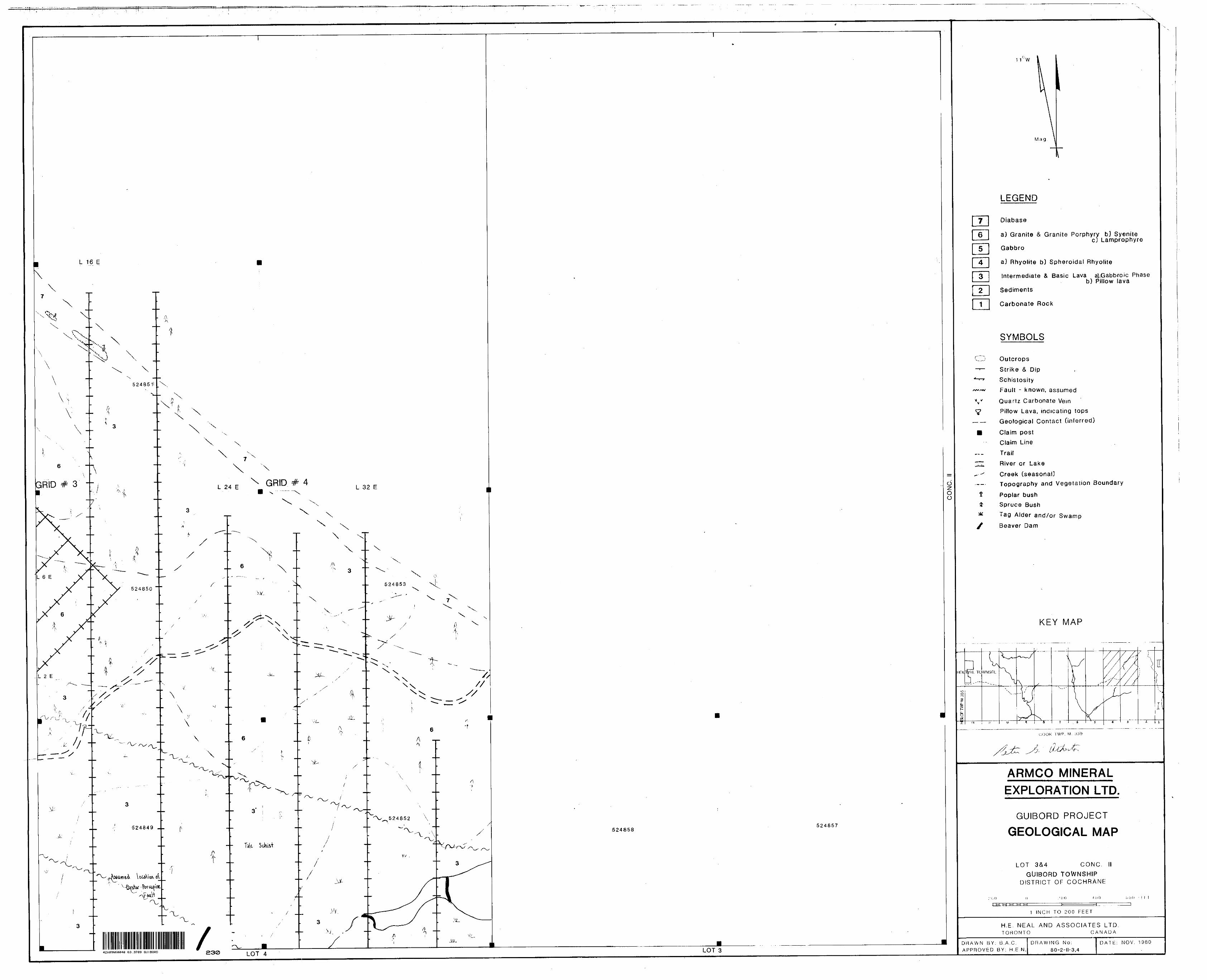
LOT 4 LOT 3
11 0 W
Mag.
LEGEND
Diabase
aj Granite fit Granite Porphyry b) Syenitec] Lamprophyre
Gabbro
aj Rhyolite b) Spheroidal Rhyolite
Intermediate A Basic Lava a) Gabbroic Phaseb) Pillow lava
Sediments
Carbonate Rock
SYMBOLS
Outcrops
Strike 6 Dip
Schistosity
Fault - known, assumed
Quartz Carbonate Vein
Pillow Lava, indicating tops
Geological Contact (inferred)
Claim postClaim Line
TrailRiver or Lake
Creek (seasonal]Topography and Vegetation Boundary
Poplar bush
Spruce Bush
Tag Alder and/or Swamp
Beaver Dam
KEY MAP
\
fe
- ""
COOK TWP. M. 339
ARMCO MINERAL
EXPLORATION LTD.
GUIBORD PROJECT
GEOLOGICAL MAP
LOT 3&4' 1 CONC.
GUIBORD TOWNSHIP' DISTRICT OF COCHRANE
200 200 400 600 FEET
1 INCH TO 200 FEET
H.E. NEAL AND ASSOCIATES LTD.TORONTO CANADA
DRAWN BY; B.A.C.
APPROVED BY: H.E.N.
DRAWING No;80-2-1-3,4
DATE; NOV. 1980
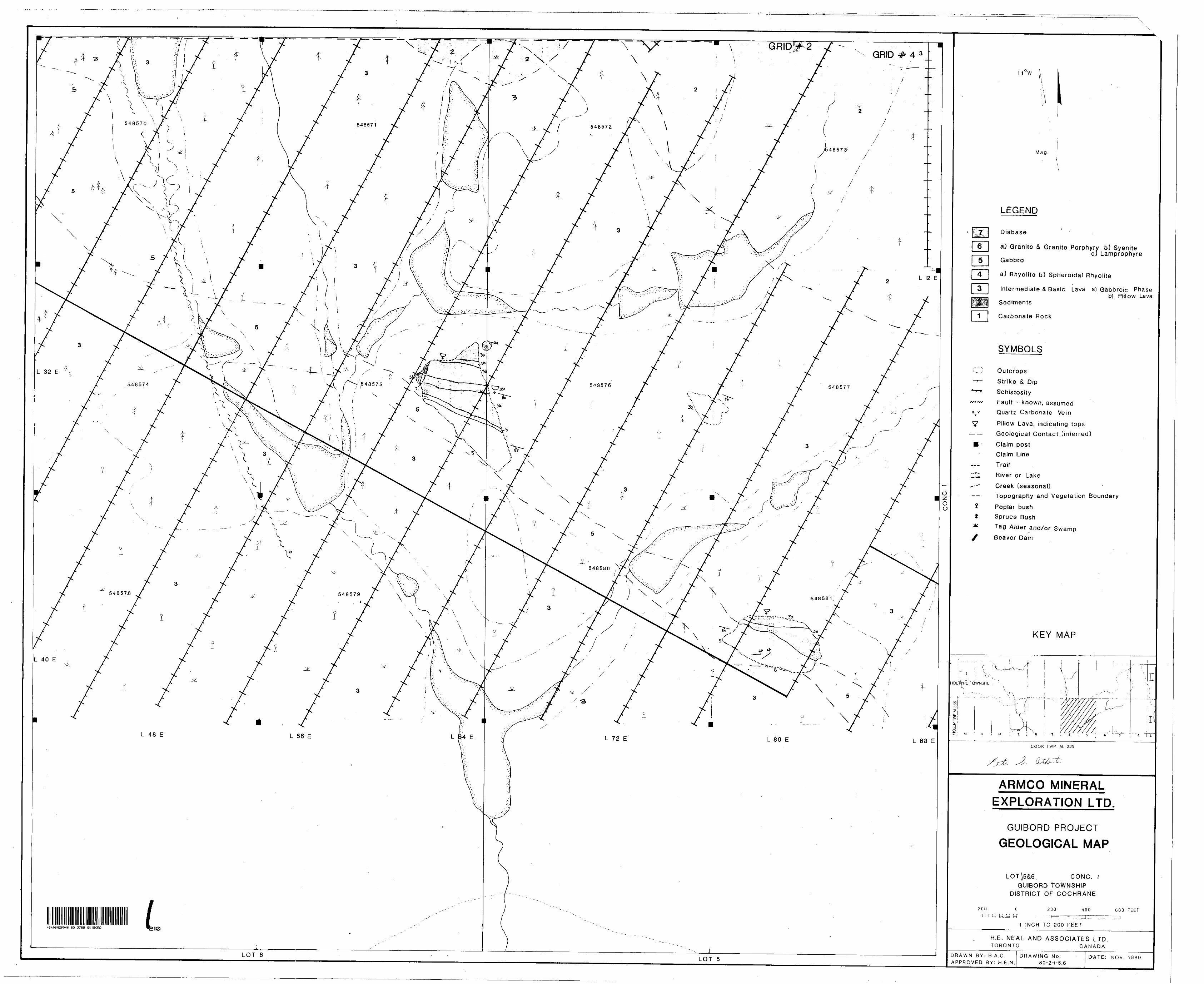
LOT 6LOT 5
11 0 W
Mag.
LEGEND
Diabase
a) Granite S Granite Porphyry b) SyenitecJ Lamprophyre
Gabbro
aj Rhyolite b) Spheroidal Rhyolite
Intermediate S Basic Lava a) Gabbroic Phaseb) Pillow Lava
Sediments
Carbonate Rock
SYMBOLS
Outcrops
Strike 8* D ip
Schistosity
Fault - known, assumedQuartz Carbonate Vein
Pillow Lava, indicating topsGeological Contact (inferred]
Claim post
Claim Line
Trail
River or Lake
Creek [seasonal)Topography and Vegetation Boundary
Poplar bush
Spruce Bush
Tag Alder and/or Swamp
Beaver Dam
KEY MAP
TC|WNSITE
I
COOK T WP. M. 339
ARMCO MINERAL EXPLORATION LTD
GUIBORD PROJECT
GEOLOGICAL MAP
LOTS5&6 CONC.b- '
GUIBORD TOWNSHIP DISTRICT OF COCHRANE
200 200 400 600 FEET
1 INCH TO 200 FEET
H.E. NEAL AND ASSOCIATES LTD.TORONTO CANADA
DRAWN BY; B.A,C. APPROVED BY; H.E.N.
DRAWING No;80-2-1-5,6
D-ATE; NOV. 1980

L 12 E L 20 EL 28 E
42A0BNE0040 63.37S9 GUIBORD 220
LOT 8 . ___L. LOT 7
Oz O O
V
*
11 0 W
Mag.
LEGEND
Diabase
a) Granite fi Granite Porphyry bJ Syenitec) Larfiprophyre
Gabbro
aj Rhyolite b) Spheroidal Rhyolite
Intermediate S Basic Lava a) Gabbroic Phaseb) Pillow lava
Sediments
Carbonate Rock
SYMBOLS
Outcrops
Strike A Dip
Schistosity
Fault - known, assumed
Quartz Carbonate Vein
Pillow Lava, indicating tops Geological Contact (inferred)
Claim post
Claim Line
TrailRiver or Lake
Creek (seasonal)Topography and Vegetation Boundary
Poplar bush
Spruce Bush
Tag Alder and/or Swamp
Beaver C.un
KEY MAP
X.H..
HOlilt/RE TCJWNSITE : Vl
x.
T ' fi
I
COOK TWP. M. 339
ARMCO MINERAL EXPLORATION LTD.
GUIBORD PROJECT
GEOLOGICAL MAP
200
TIE
LOT 7S.8 CONC,GUIBORD TOWNSHIP
DISTRICT OF COCHRANE
O 200 400
1 INCH TO 200 FEET
600 KFET
H.E. NEAL AND ASSOCIATES LTD TORONTO CANADA
DRAWN BY; B.A.C. APPROVED BY; H.E.N.
DRAWING No. 80-2-I-7
DATE; NOV. 1980
42A0BNE0040 63.3789 GUIBORD 230 LOT 4LOT 3
6
V
7
11 C W
Mag
LEGEND
Diabase
a) Granite d Granite Porphyry b) Syenitec) Lamprophyre
Gabbro
a] Rhyolite b) Spheroidal Rhyolite
Intermediate
Sediments
Basic Lava a^Gabbroic Phase b) Pillow lava
Carbonate Rock
SYMBOLS
Outcrops
Strike d Dip
Schistosity
Fault - known, assumed
Quartz Carbonate Vein
Pillow Lava, indicating tops
Geological Contact (inferred)
Claim post
Claim Line
Trail
River or Lake
Creek [seasonal]
Topography and Vegetation Boundary
Poplar bush
Spruce Bush
Tag Alder and/or Swamp
Beaver Dam
KEY MAP
COOK TWP. M. J39
ARMCO MINERAL
EXPLORATION LTD.
GUIBORD PROJECT
GEOLOGICAL MAP
LOT S&4 CONC. IIGUIBORD TOWNSHIP
DISTRICT OF COCHRANE
!'(M) l)
l M t-l M Ul M
1 It O
1 INCH TO 200 FEET
H.E. NEAL AND ASSOCIATES LTD.TORONTO CANADA
DRAWN BY: B.A,C.
APPROVED BY: H.EN.
DRAWING No:80-2-11-3,4
DATE: NOV. 1980

GRID # 3
42A08NE0040 63.3769 GUIBORD S40LOT 6 LOTS
v
9
tM.
1 1 W
LEGEND
Diabase
a) Granite 8* Granite Porphyry b] Syenitec) Lamprophyre
Gabbro
a) Rhyolite b) Spheroidal Rhyolite
Intermediates Basic Lava a) Gabbroic Phaseb) Pillow lava
Sediments
Carbonate Rock
SYMBOLS
Outcrops
Strike A Dip
Schistosity
Fault - known, assumed
Quartz Carbonate Vein
Pillow Lava, indicating tops
Geological Contact (inferred)
Claim post
Claim Line
Trail
River or Lake
Creek (seasonal]Topography and Vegetation Boundary
Poplar bush
Spruce Bush
Tag Alder and/or Swamp
Beaver Dam
KEY MAP
ARMCO MINERAL
EXPLORATION LTD.
GUIBORD PROJECT
GEOLOGICAL MAP
LOT 5&G CONC, l i GUIBORD TOWNSHIP
DISTRICT OP COCHRANE
200 O
H
200 400 600 FEETT
INC
H.E MEAL AND ASSOCIATES LTDTOHON l O CANADA
i Hi A W IN C No,80-2-11-5,6
DAT \ N OV. 1980
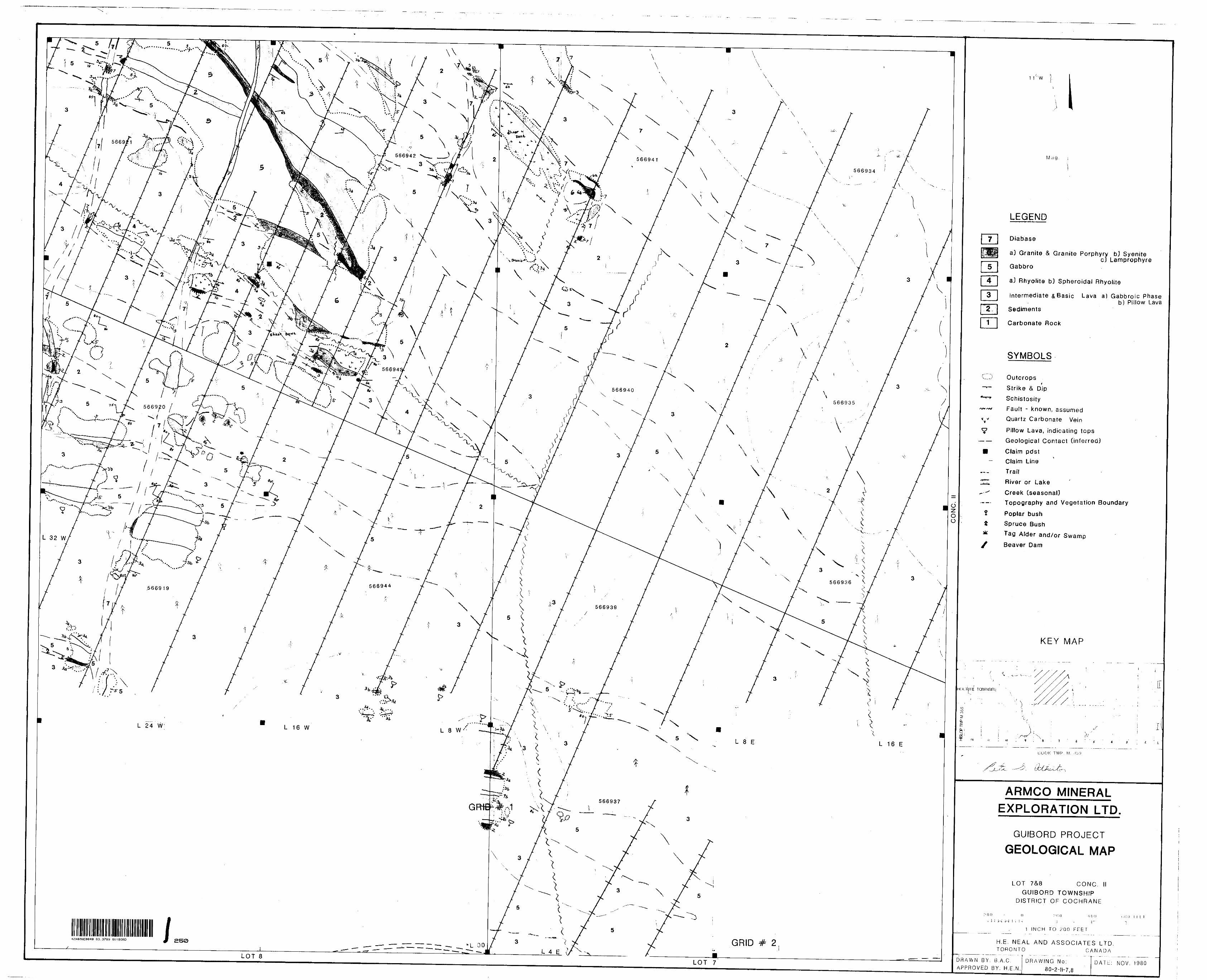
LOT 8LOT 7
X V V
LEGEND
Diabase
a) Granite A Granite Porphyry b) Syenitec) Lamprophyre
Gabbro
aJ Rhyolite b3 Spheroidal Rhyolite
Intermediate a Basic Lava a) Gabbroic Phaseb) Pillow Lava
Sediments
Carbonate Rock
SYMBOLS
Outcrops
Strike 3t Dip
Schistosity
Fault - known, assumedQuartz Carbonate Vein
Pillow Lava, indicating tops Geological Contact (inferred)
Claim pdst\
Claim Line
Trail
River or Lake
Creek (seasonal]Topography and Vegetation Boundary
Poplar bush
Spruce Bush
Tag Alder and/or Swamp
Beaver Dam
KEY MAP
I4 3
ARMCO MINERAL EXPLORATION LTD.
GUIBORD PROJECT
GEOLOGICAL MAP
LOT 78,8 CONC. IIGUIBORD TOWNSHIP
DISTRICT OF COCHRANE
1 INCH TO 200 FEET
H.E. NEAL AND ASSOCIATES LTD.TORONTO CANADA
DRAWN BY. B,A,C, APPROVED BY; H.E.N.
DRAWING No,80-2-11-7,8
DATL: NOV. 1980
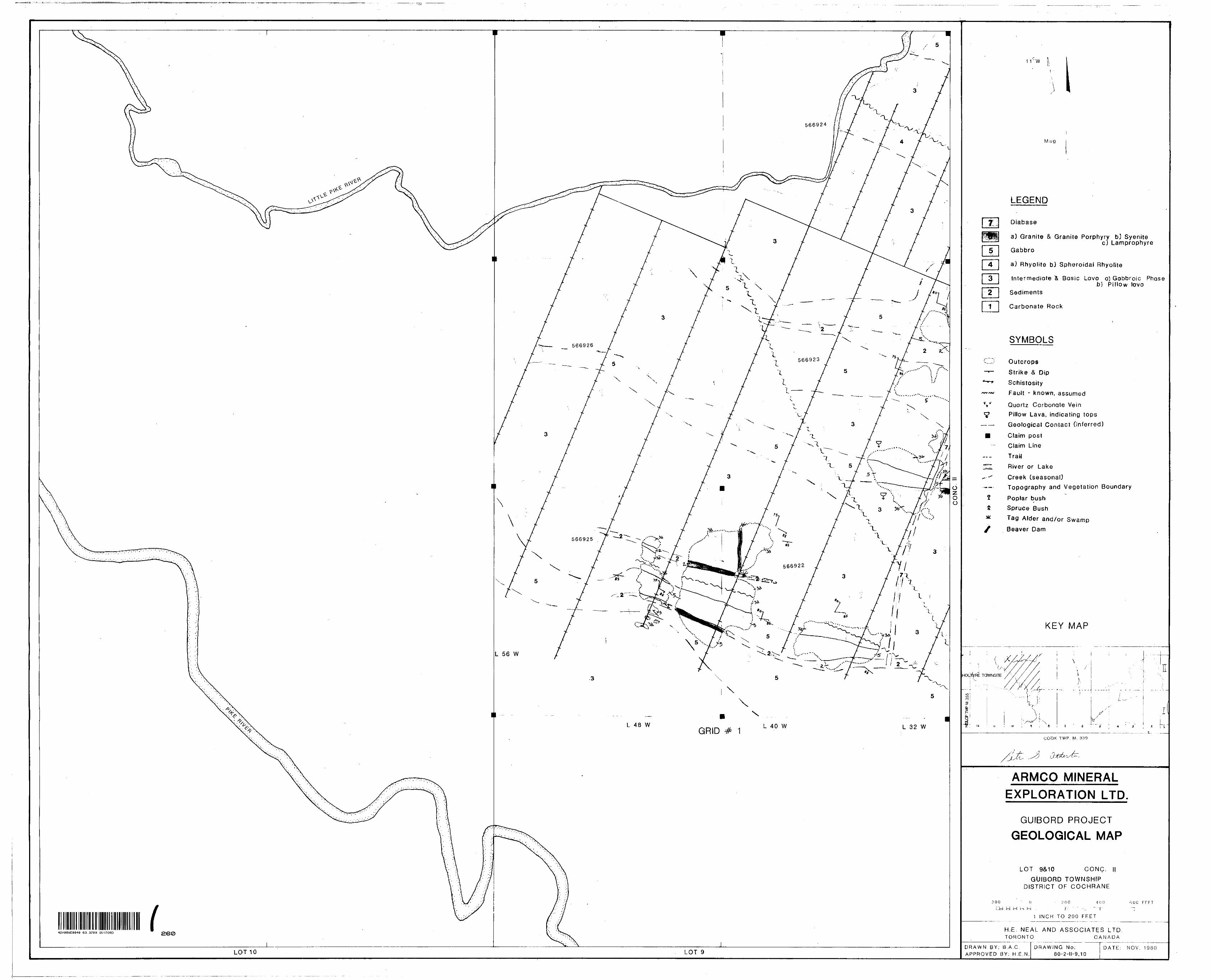
LOT 10
V
7
1 1 'W
Mag.
LEGEND
Diabase
a) Granite S Granite Porphyry bJ Syenitec) Lamprophyre
Gabbro
a) Rhyolite b) Spheroidal Rhyolite
Intermediate^ Basic Lava a) Gabbroic Phaseb) Pillow lava
Sediments
Carbonate Rock
SYMBOLS
Outcrops
Strike 8. Dip
Schistosity
Fault - known, assumed
Quartz Carbonate Vein
Pillow Lava, indicating tops
Geological Contact (inferred)
Claim post
Claim Line
Trail
River or Lake
Creek (seasonal)
Topography and Vegetation Boundary
Poplar bush
Spruce Bush
Tag Alder and/or Swamp
Beaver Dam
KEY MAP
TciWNSITE
In , i c 4 J
CO'OK TWP. M. 339
ARMCO MINERAL
EXPLORATION LTD.
GUIBORD PROJECT
GEOLOGICAL MAP
LOT 9&10 CONC.
GUIBORD T OWNSHIP DISTRICT OF COCHRANE
300 (l - 200 400
fltJ H M M 1-1 . F- " -; ~-^T"
l INCH TO 200 FEET
O O IT F T
H/E. NEAL AND ASSOCIATES LTD. TORONTO CANADA
DRAWN BY; B,A.C,
APPROVED BY; H.E.N.
DRAWING No:80-2-11-9,10
DATE: NOV. 1980

CONC. V
LOT 11 LOT 12
V V V
MM'
7-f
o 1 1 W
Mag.
LEGEND
Not Stragraphic Order
Mafic Intrusive
Mafic Volcanics
Intermediate Volcanics
Mixed Mafic Volcanics and Talc Schist
SYMBOLS
Outcrop
Strike S Dip
Schistosity
Fault- known, assumed
Carbonatized Rock
Pillow lav a indicating .t ops
Geological Contact (inferred]
Claim Post
Claim L ine
Township Road
Trail,;
Bridge
River
Creek (seasonal)
Gully
Slope of terrain
Topography, and Vegetation Boundary
Poplar bush
Spruce bush k
Tag alder and Swamp
Boavor dam
Tag Alder
KEY MAP
ARMCO MINERAL EXPLORATION LIMITED
GUIBORD PROJECT
GEOLOGICAL MAP
LOT 11&12 CONC.
GUIBORD T OWNSHIP DISTRICT OF COCHRANE
IV
200 200 400 600 FEE"
1 INCH TO 200 FEET
H,E. NEAL AND ASSOCIATES LTD. TORONTO CANADA
DRAWN BY: M.M.G.
APPROVED BY: H.E.NDRAWING No:
80-2-IV-1 1,12DATE: SEPT. 19

Co
h
1 \ ' ' ~- — --"ir.0 10 O ~, 0 tf-i^i m f"* -^ ^e to-tp *o (D tr* --p-—-
^
4IH
4H
•B
~V^
\
\
S
xx ' ™'\
\ —
•^*.-. ^os— 7iOfd6Se~
*^5?oS8&-52^0•430-w4^0''
•1'K-•-IfcO-^0'^OC•37037^-36o330
•370-35b~3lD
33d•^•3^o"VJc?i^•^50 "-250-23dZZO•2^0•2.1*-#3-^6•/go-f 3o-/9o•(W•i 70•/5"n-/8"/5"0
•t&Q./70— 'SO790•/se•?40-/aov/^•y^o
• IffaL/7C
OZ O O
LOT 4 LOT 3
1 1 W
Mag
LEGEND
- over 3000 K
- 2500 y
- 2000 y- 1500 if
- 1000 Jf
- 500 r
- o v
SYMBOLS
Base Station (secondary B.S.every 800 ft.]
Contour Interval 100 y
INSTRUMENT
SCINTREX MF 1 FLUXGATE MAGNETOMETER
KEY MAP
^'
4
TC WNSI1L
COOK TWP M, ;i39
EXPLORATION LTD.
GUIBORD PROJECT
GROUND MAGNETOMETER SURVEY
LOT S&4 CONC. l
GUIBORD TOWNSHIP DISTRICT OF COCHRANE
?()0 l- - "
1 INCH TO 200 FEET
600 TLET
H.E. NEAL AND ASSOCIATES L TD. TORONTO CANADA
DRAWN BY; B.A.C APPROVED BY: H.E.N.
DRAWING No: 80-2-1-3,4
DATE: NOV. 1980
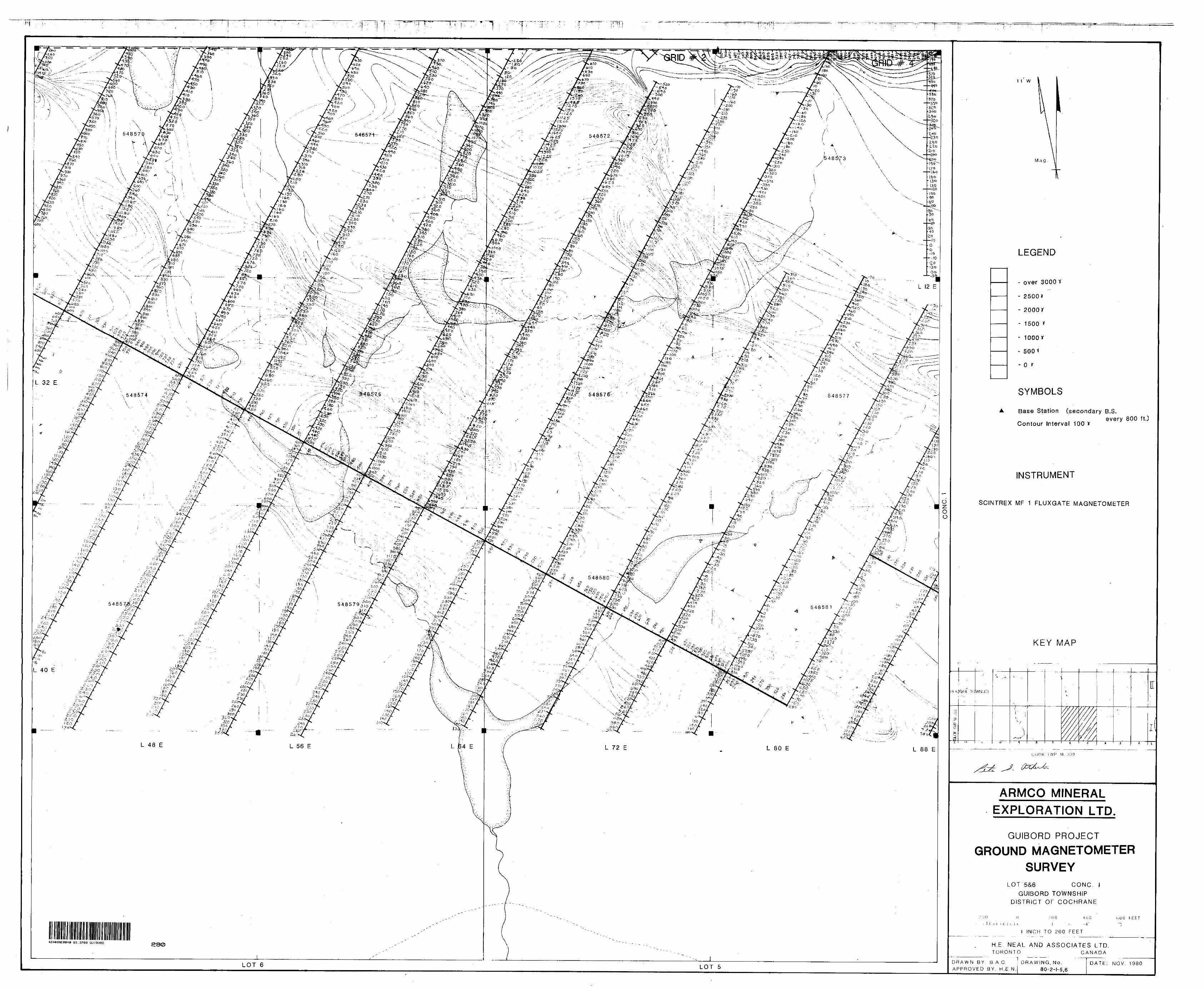
•T
42A08NE0040 63.3789 GUIBORD
LOT 6 LOT 5
1 1 W
Mag
LEGEND
- over 3000 Y
- 2500 J
- 2000V
- 1500 *
- 1000V
- 500 -i
- O r
SYMBOLS
Base Station (secondary B.S.every 800 ft.)
Contour Interval 100 *
INSTRUMENT
SCINTREX MF 1 FLUXGATE MAGNETOMETER
KEY MAP
COOK l WP M. :*39
ARMCO MINERAL EXPLORATION LTD.
GUIBORD PROJECT
GROUND MAGNETOMETER SURVEY
LOT-5&6 CONC. l
GUIBORD TOWNSHIP DISTRICT OF COCHRANE
t.UO"l
1 INCH TO 200 FEET
H.E. NEAL AND ASSOCIATES LTD. TORONTO CANADA
DRAWN BY. B.A.C
APPROVED BY; H.E.N.
DRAWING, No:80-2-1-5,6
DATE: NOV. 1980
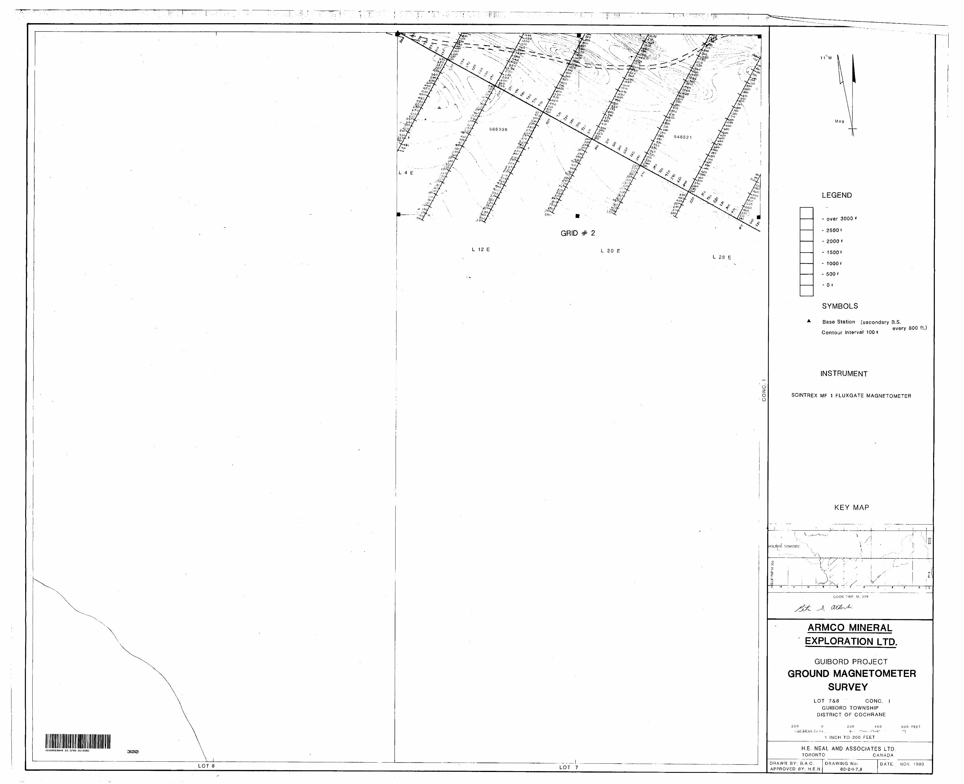
i M
GRID
L 12 E L 20 EL 28 E
O~z. O O
63.3789 GUIBORD 300
LOT 8. - —L.
LOT 7
11
Mag
LEGEND
- over 3000 *
- 2500 it
- 2000v
- 1500 Y
- 1000 y
- 500*
- O f
SYMBOLS
Base Station Csecondary B.S.every 800 ft.)
Contour Interval 100 K
INSTRUMENT
SCINTREX MF 1 FLUXGATE MAGNETOMETER
KEY MAP
TOWNSITE
o?
Ii l
COOK TWP. M. 339
ARMCO MINERAL EXPLORATION LTD.
GUIBORD PROJECT
GROUND MAGNETOMETER SURVEY
LOT 7&S CONC. lGUIBORD TOWNSHIP
DISTRICT OF COCHRANE
200 O 200 400H h-- ~ —— - -~-^T
1 INCH TO 200 FEET
600 FEET
H.E. NEAL A ND ASSOCIATES L TD TORONTO CANADA
DRAWN BY: B.A,C, APPROVED 8Y: H.E.N,
DRAWING No:80-2-1-7,8
DATE: NOV. 1980

LEGEND
~ over 3000?
- 2500^
- 2000*
- 1500 *"
- 500 y
- OY
SYMBOLS
Base Station Csecondary B.S.every 800 ft.)
Contour Interval 100 X
INSTRUMENT
SCINTREX MF 1 FLUXGATE MAGNETOMETER
KEY MAP
ARMCO MINERAL
EXPLORATION LTD.
GUIBORD PROJECT
GROUND MAGNETOMETER SURVEY
M ) l S&4 . ,oNr; II
GUIBORD TOWNSHIP
80-2-11-3,4NOV. 1980
42A08NE0040 63.3789 GUIBORD 310

' i"'. ; t" r'
LOT 6
LEGEND
- over 3000 *
- 2500 y
- 2000 r
- 1500 *
- 1000 vi
- 500 y
- o y
SYMBOLS
Base Station [secondary S.S.every 800 ft.)
Contour Interval 100 Y
INSTRUMENT
SCINTREX MF 1 FLUXGATE MAGNETOMETER
KEY MAP
ARMCO MINERAL
EXPLORATION LTD.
GUIBORD PROJECT
GROUND MAGNETOMETERSURVEY
i o l 5&S CONC; It
GUIBORD TOWNSHIPois l nic r oi t;t;(;HR ANI
200c:
200 400 600 FE-ET
80-2-M-5.6NOV. 1980
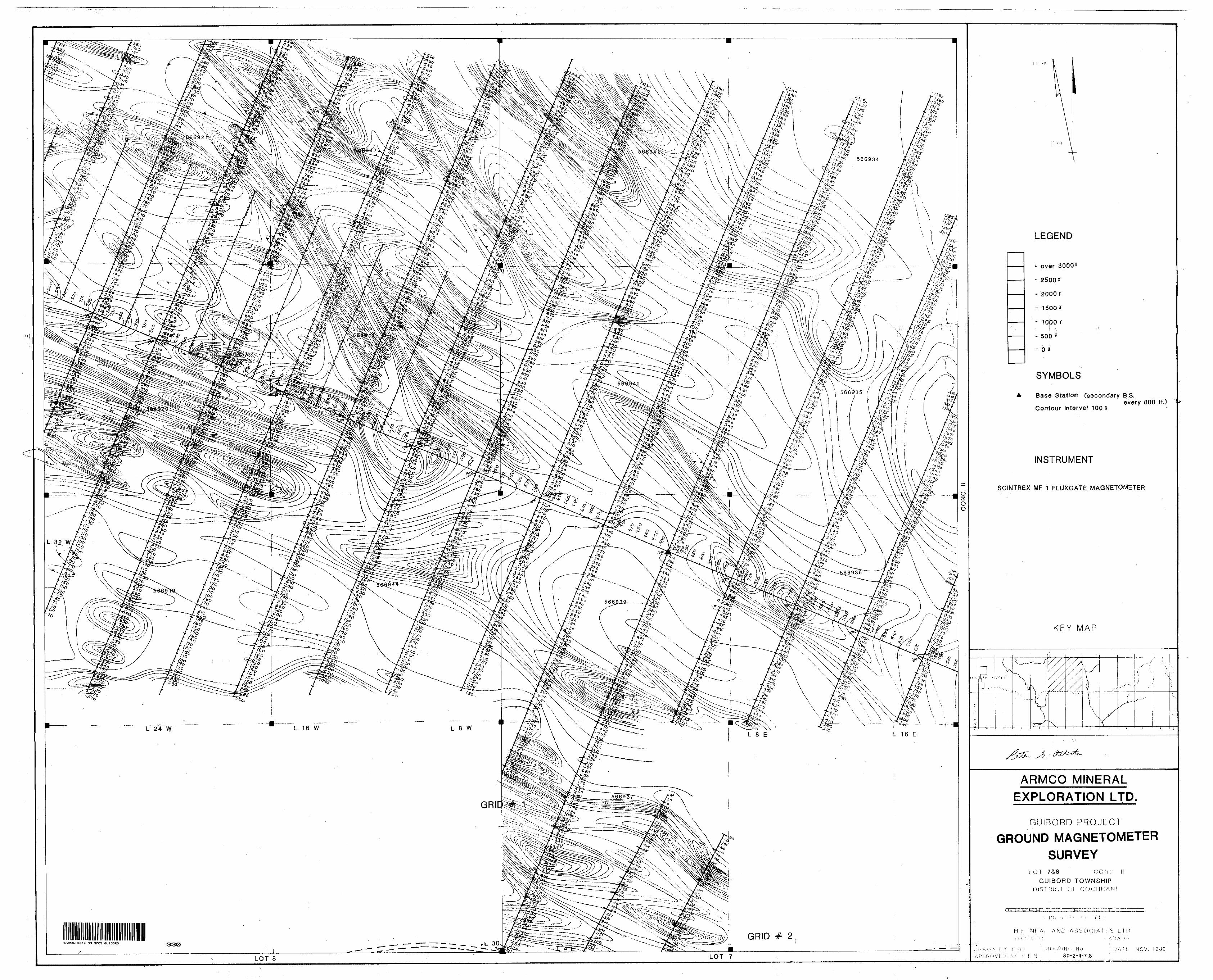
42A08NEa040 63.3789 GUIBORD
LOT 7
LEGEND
L over 3000*
- 2500*
- 2000 r
- 1500 X
- 1000 if
- 500 *
- o if
SYMBOLS
Base Station Csecondary B.S.every 800 ft.)
Contour Interval 100 if
INSTRUMENT
SCINTREX MF 1 FLUXGATE MAGNETOMETER
KEY MAP
ARMCO MINERAL
EXPLORATION LTD.
GUIBORD PROJECT
GROUND MAGNETOMETER
SURVEYLOT 7&S ' CONC: I I
GUIBORD TOWNSHIPDIST RK: l Of COCHHANF
M i-i
H.F NE" Ai AND ASSOCIAll S LID
f"-; -\ '/; IN' . No
80-2-II-7.8M : i NOV. 1980
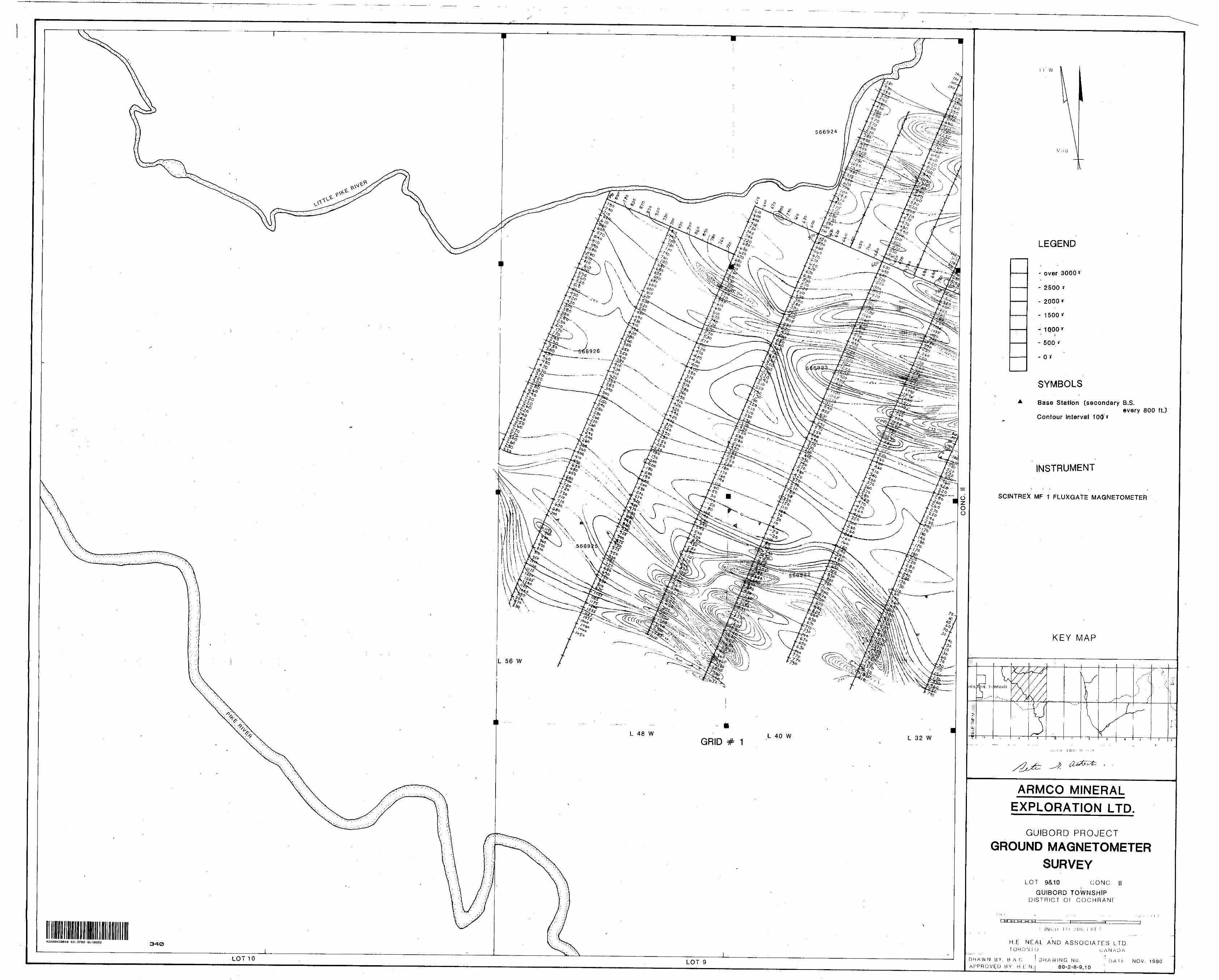
LOT 10 LOT 9
w
LEGEND
i ' '
- over 3000*
- 2500 *
- 2000*
- 1500*
- 1000v
- 500 i'
- O*
SYMBOLS
Base Station [secondary B.S.every 800 ft.]
Contour Interval 100 *
INSTRUMENT
SCrNTREX MF t FLUXGATE MAGNETOMETER
KEY MAP
ARMCO MINERAL EXPLORATION LTD,
GUIBORD PROJECT
GROUND MAGNETOMETERSURVEY
LOT 9&10 GONG I IGUIBORD TOWNSHIP
DISTRICT Of COCHRANE
-FTT-I Ul l-l
H.E NEAL A ND ASSOCIATES LTD,T O H C) N ( O C A N A D A
DRAWN BY. BAG 'DRAWING No, DA l K NOV. 1980 APPROVED BY. H L" N. 8 0-2-11-9,10 |
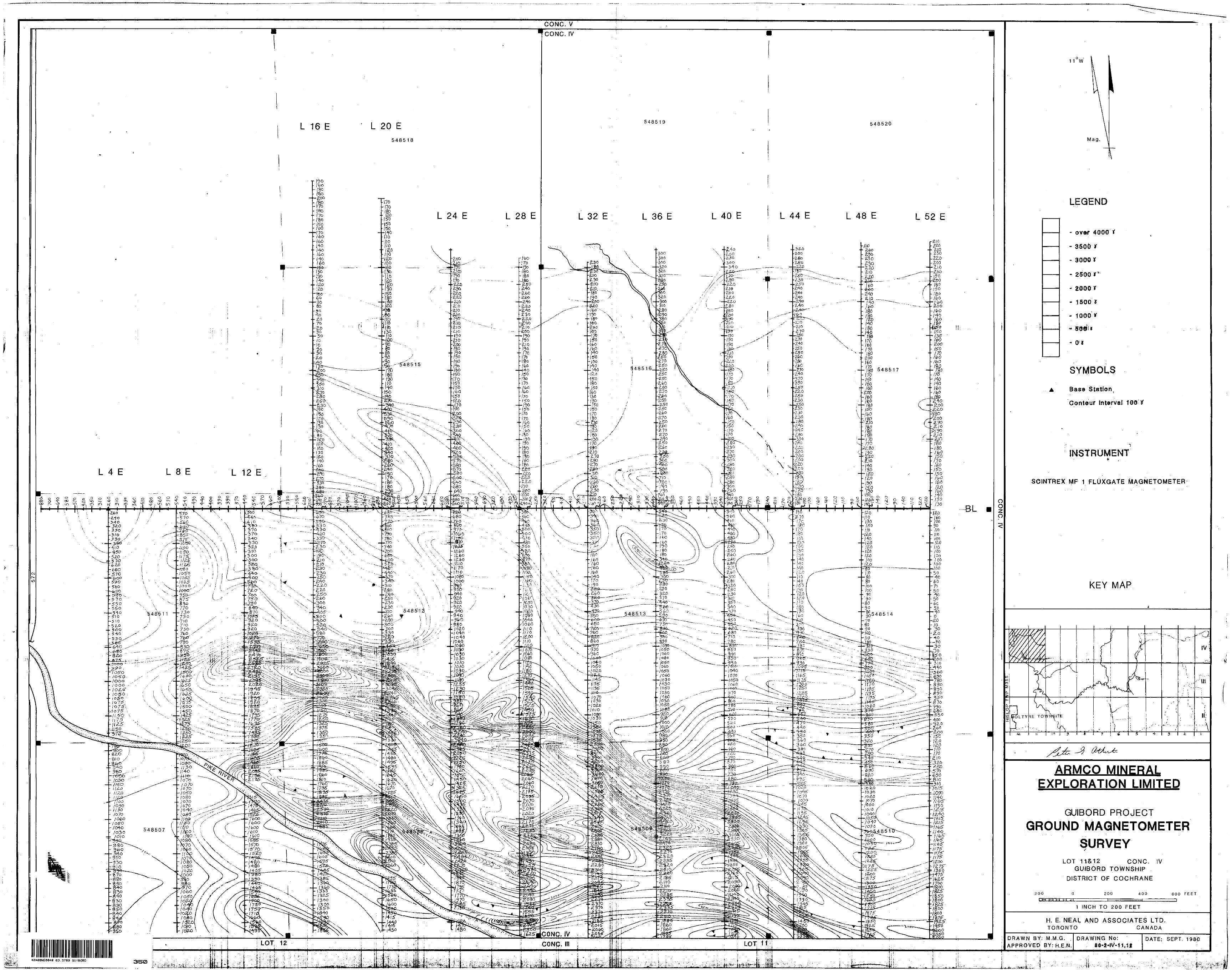
GONG. V
CONC. IV
L 20 EL 16 E
LEGEND
L 28 E L 32 E L 36 E
- over 4000 i
- 3500
- 3000
SYMBOLS
Base Station,
Contour interval 100-*
INSTRUMENT
SOINTREX MF 1 FLUXGATE MAGNETOMETER
KEY MAP
-380 90
/oJ 050
-/060 ogo
JO GO
JO'30 /030
h f 05"0 /030 /060
350 — 32.0
ARMCO MINERAI EXPLORATION LIMITED
GUIBORD PROJECT
GROUND MAGNETOMETERSURVEY
LOT 11&12 CONC. IV GUIBORD TOWNSHIP
DISTRICT OF COCHRANE
1 INCH TO 200 FEET
H. E. MEAL A ND ASSOCIATES LTD. TORONTO CANADA
DRAWN BY: M.M.G. , APPROVED BY: H.E.N.
DRAWING No DATE: SEPT. 1984DLOT 12 CONC. Ill
42A0BNEC040 63.3789 GUIBORD
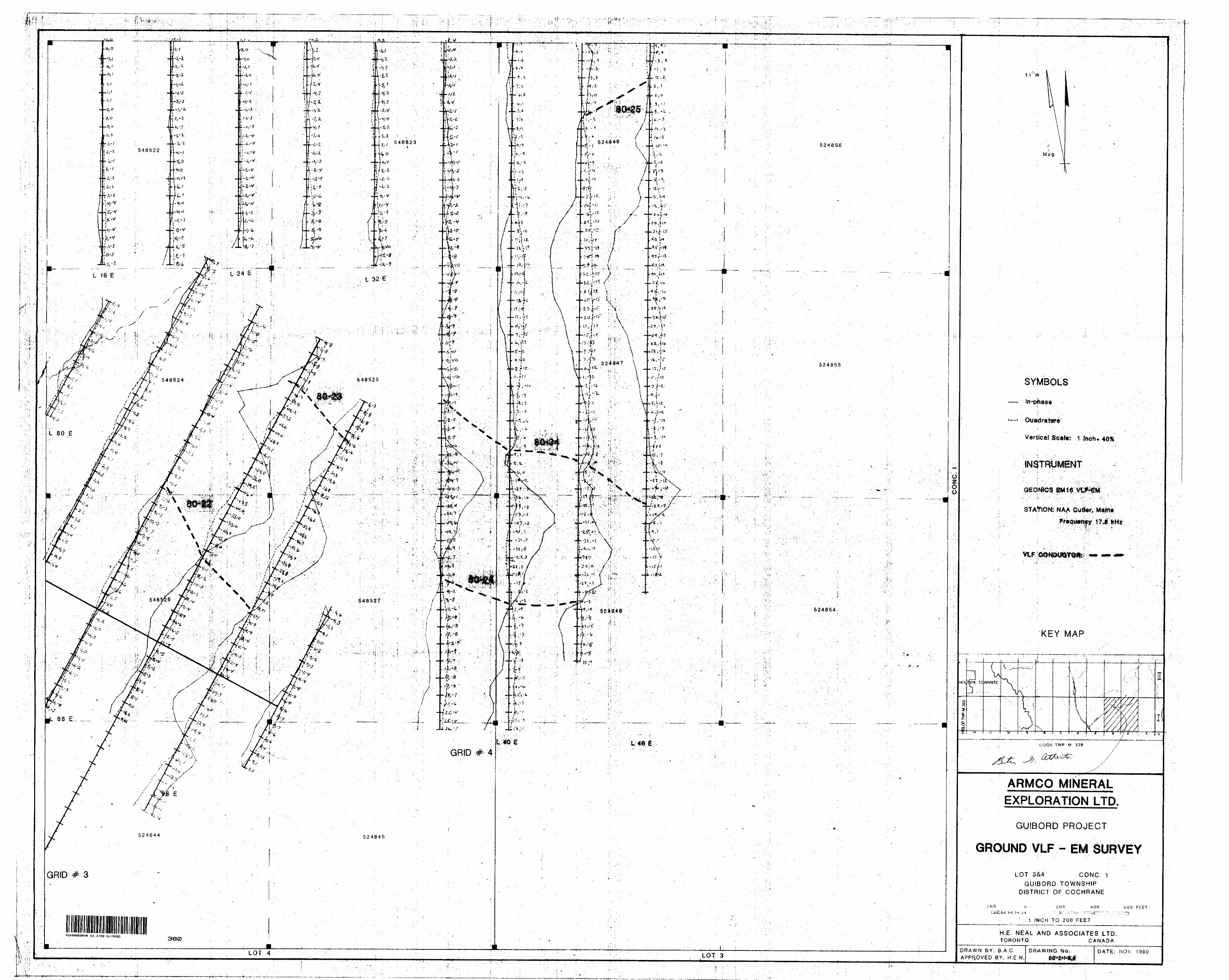
SYMBOLS
Quadrature
Vertical Scale: 1 }hoh
NAA Cutef. M*irrd
'KEY MAP
ARMCO MfNERALEXPLORATION LTD.
GUIBORD PROJECT
GROUND VLF ~ EM SURVEY
LOT S&4 CONC,GUIBORD TOWNSHIP
DISTRICT OF COCHRANE
1 INCH TO 200 FEET
H.E. NEAL AND ASSOCIATES LTD. TORONTO CANADA
42A08NEa040 63.3789 GUIBORD
DRAWN BY: B.A.C
APPROVED BY; H.E.N.DATE: NOV, 1980

SYMBOLS
In-phase
Quadrature
Vertical Scale: l Inon^ *4'OX
INSTRUMENT
STATION: NAA Gulfeff Main*
KEY MAP
ARMCO MINERALEXPLORATION LTD.
GUIBORD PROJECT
EM SURVEYGROUND VLF
LOT 5&G - CONC.GUIBORD TOWNSHIP -
DISTRICT OF COCHRANE
H.E. NEAL AND ASSOCIATES LTD. TORONTO CANADA
42A0BNEeC40 63.3789 GUIBORD
DRAWN BY; B.A.C APPROVED BY: H.E.N.
DATE: N OV. 1980
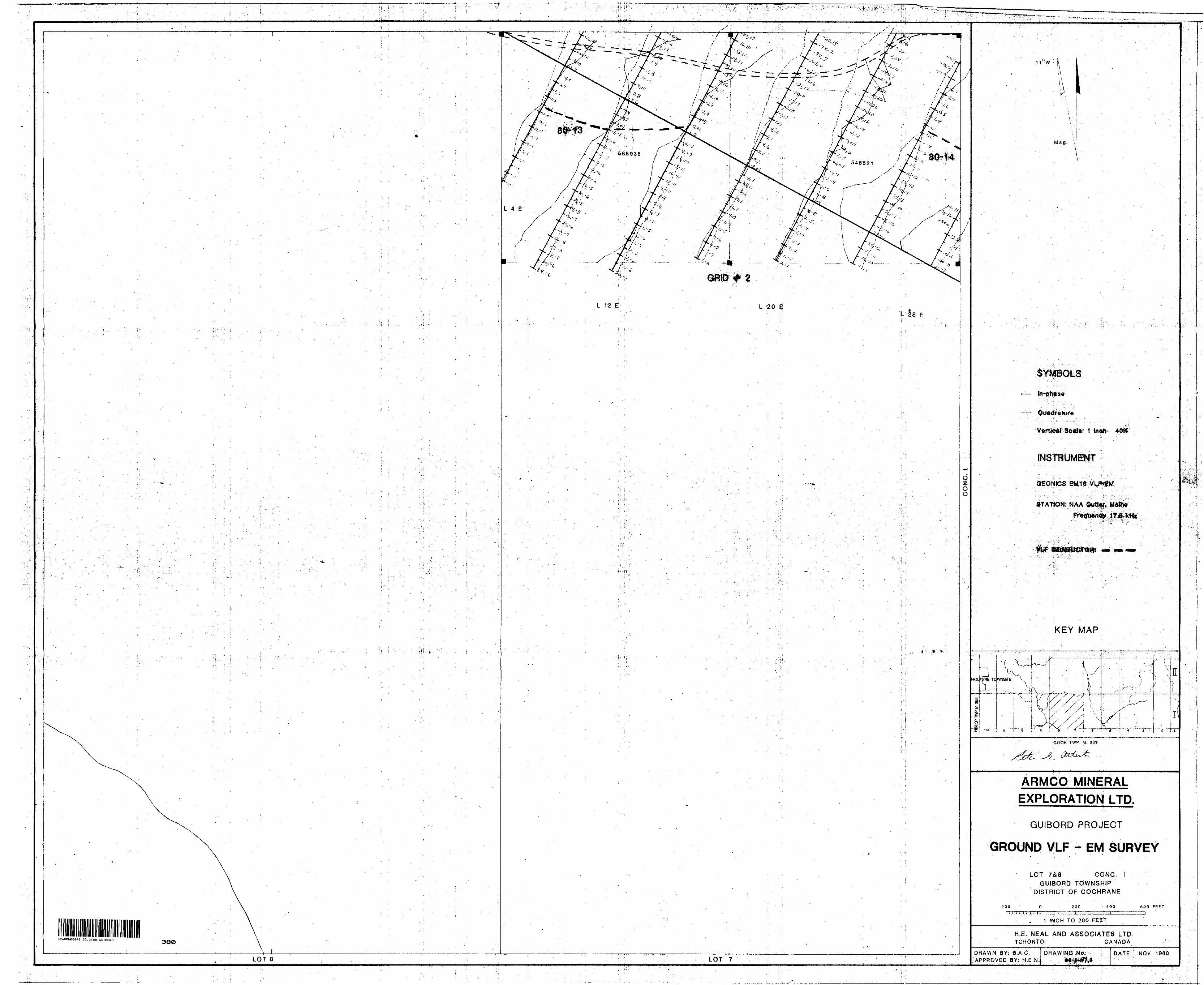
J t .
42AeaNE0a40 63.3789 GUIBORD380
LOT 8
L 12 E L 20 E
LOT 7
L 28
*:.- -.*-
! f
oz o o
Mag,
^IfrW*'*. -t -."t . '-T W ,
KEY MAP
CO'OK TWP. M, 339
ARMCO MINERAL EXPLORATION LTD.
GUIBORD PROJECT
GROUND VLF- EM SURVEY
LOT 7&S CONC.
GUIBORD TOWNSHIP
DISTRICT OF COCHRANE
200 Oi t-j t^i "tr?-^ t-j
200 400 600 FEET
1 INCH TO 200 F EET
H.E. NEAL AND ASSOCIATES LTPTORONTO, CANADA
DRAWN BY; Q-A.C. APPROVED BY: H.E.N
DRAWING NO, DATE: N OV. 1980
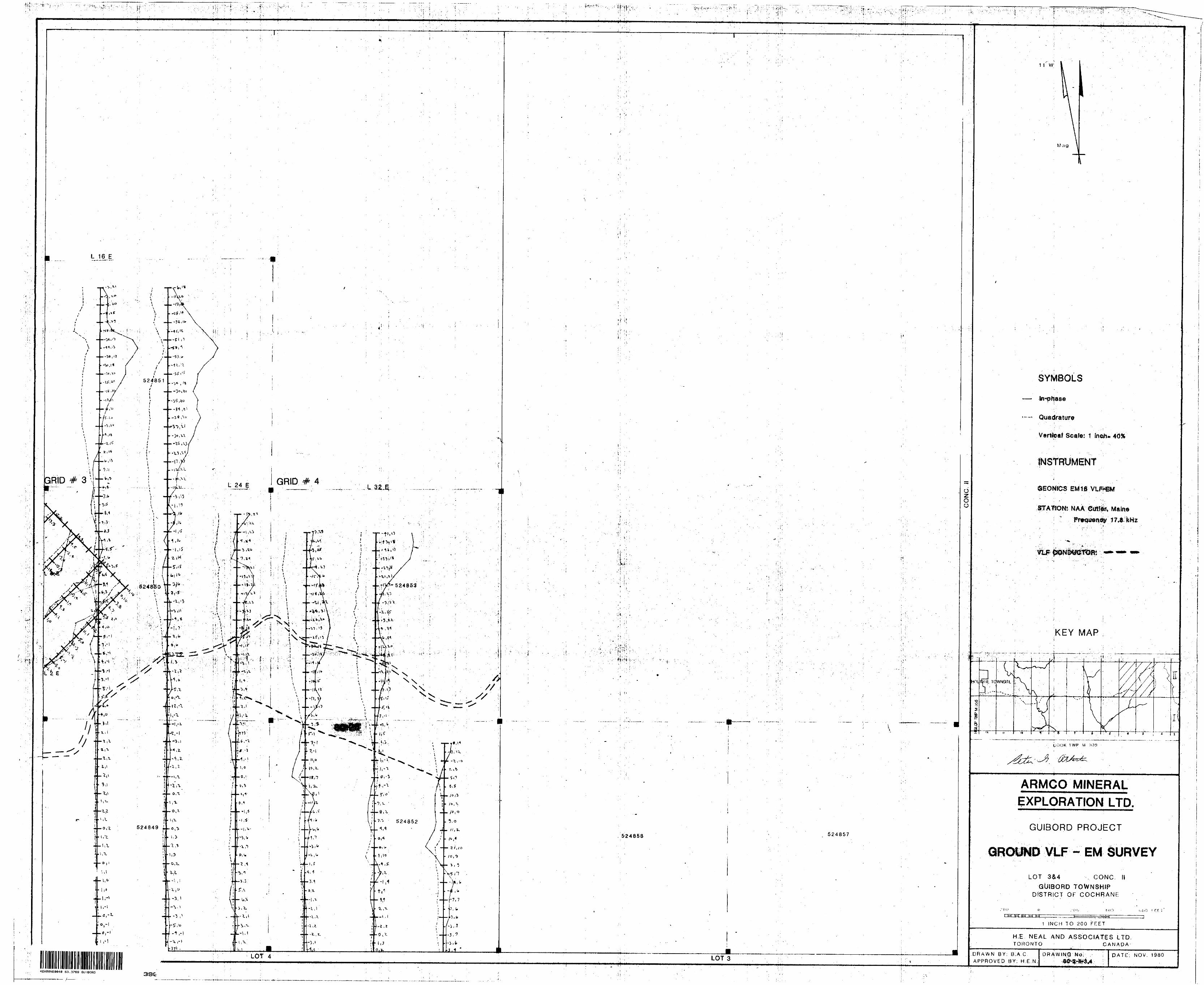
Oz o o
1 1 W
W,i g
SYMBOLS
In-phase
Quadrature
Vertfeaf Scale: 1 fnc^i* 40X
©EONfOS EMtfi
STTAtlONl NAA ©011^ Maine17,3 kHz
KEY MAP
I
l WP M :*39
ARMGO MINERAL EXPLORATION LTD.
GUIBORD PROJECT
-VLF-- EM SURVEY
LOT S&4 , CONC. II
GUIBORD TOWNSHIPDISTRICT OF COCHRANE
1-1•1U O i. oo f frr s
1 INCH TO 200 FEET
H.E NEAL AND ASSOCIATES LTD.TORONTO CANADA-
DRAWN BY; 8,A C APPROVED BY; H.E.N.
DRAWING No; DATE: NOV. 1980
42A08NEa043 B3.37B9 GUIBORD
^f , . .u^.,^— i__3SC:
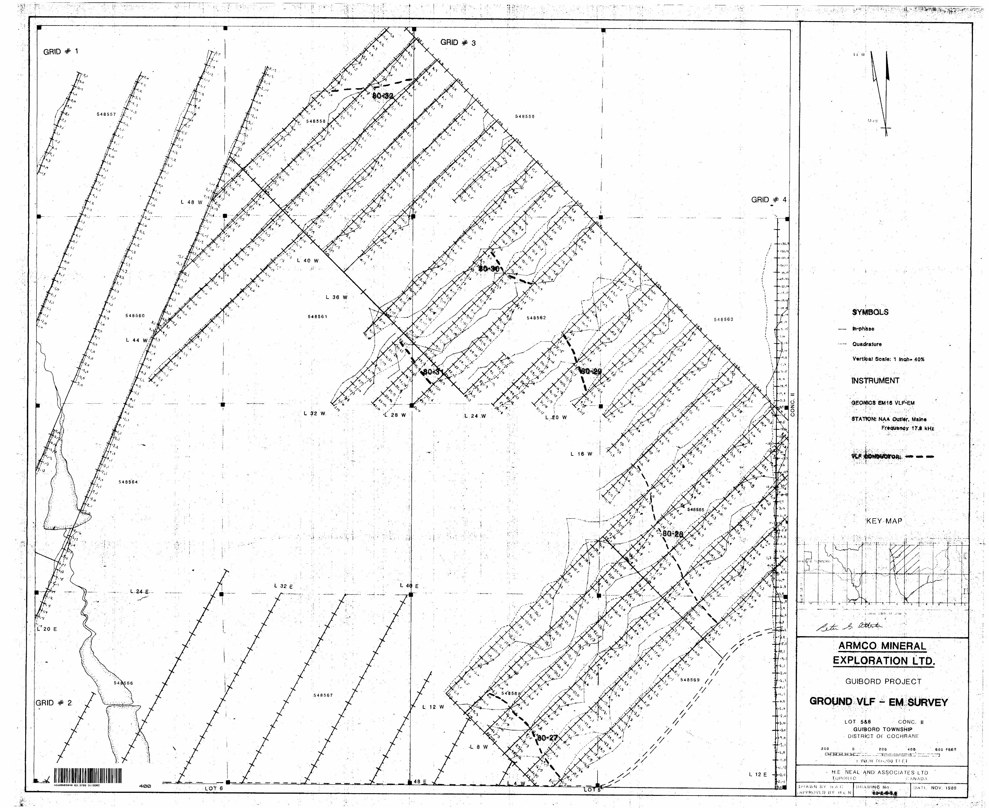
s--. :tt:
42AaBNE(S04ia 63.3789 G UIBORD 4(2)0 LOT 6
u w
V^rtfeal Scale; 1 4056
VLF^EM
3TAHON1 NAA
KEY MAP
i.i i (K i W l-' :m -* r
ARMCO MiNERAL EXPI.OBATION LTD.
GUIBORD PROJECT
LOT S&6 CONC. li GUIBORD TOWNSHIP
DISTRICT or COCHRANE:
200L-ta—ea—c7i..
200
l lNk.;H f O-.'OO f 1 ; Fi
400. 600
H.E NEAL AND ASSOCIATES LTD"" i;A.NAl)A
[JH A W N BY H A (; Al'h'ROVLO BV- H L
DRAWING "NO !)ATK N OV. 1980
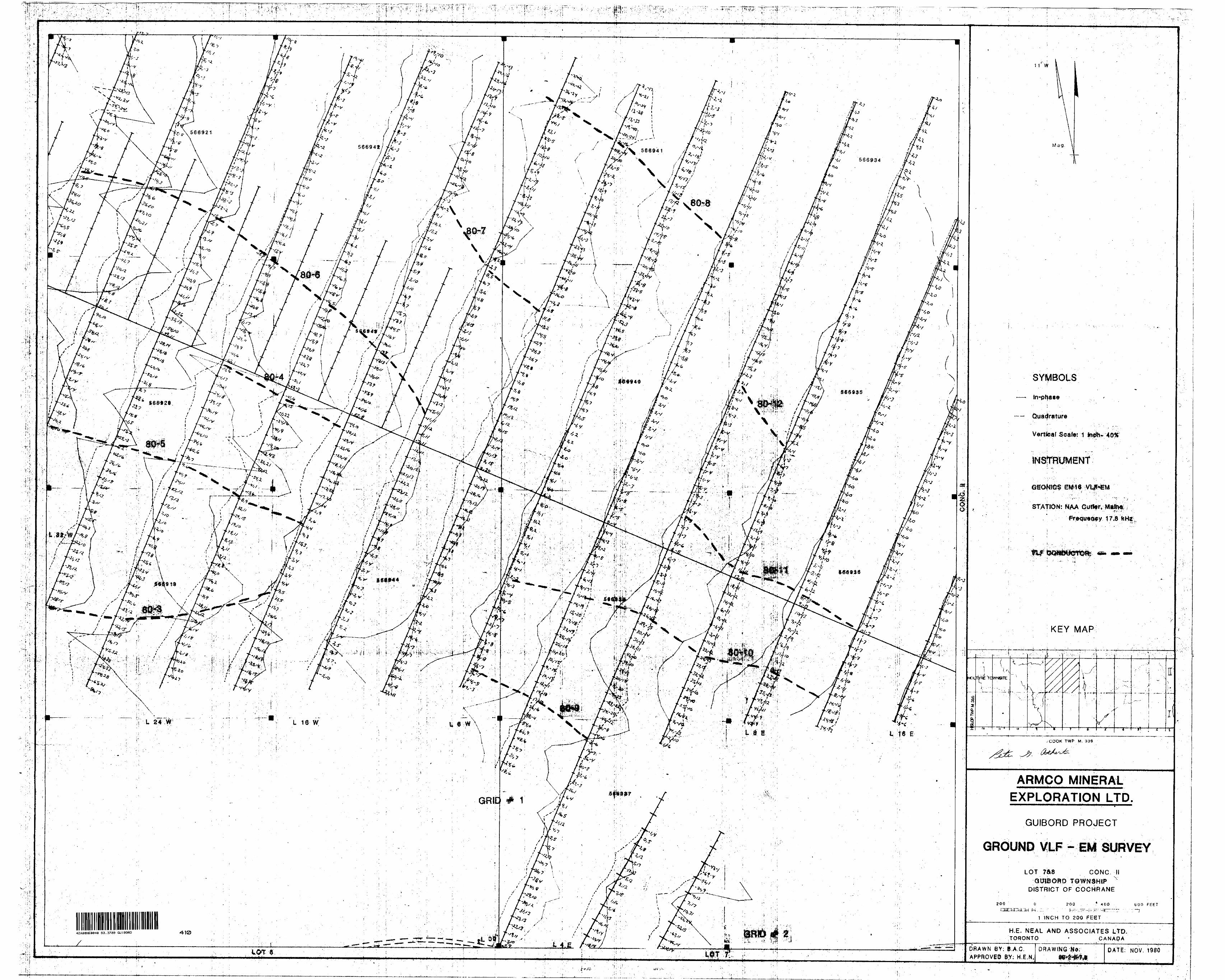
\ -' r\ \ f'#^
SYMBOLS
Quadrature
Vertfeftf .Soata 1 fn*8i- -40*
EMM*
STATION: NAA
KEY MAP
.COOK TWP M. 339
ARMCO MINERALEXPLORATION LTD.
GUIBORD PROJECT
GROUND VLF - EM SURVEY
LOT 7ft8 CONC, tl•Qtirifi
DISTRICT OF COCHRANE
INCH TO 200 FEET
H.E, NEAL A ND ASSOCIATES LTD. TORONTO - CANADA
42A08NE004CI 63.3789 GUIBORD
DRAWN BY: B.A.C. APPROVED 8Y; H.E.N,
DRAWINQ-NO DATE: NOV. 1980
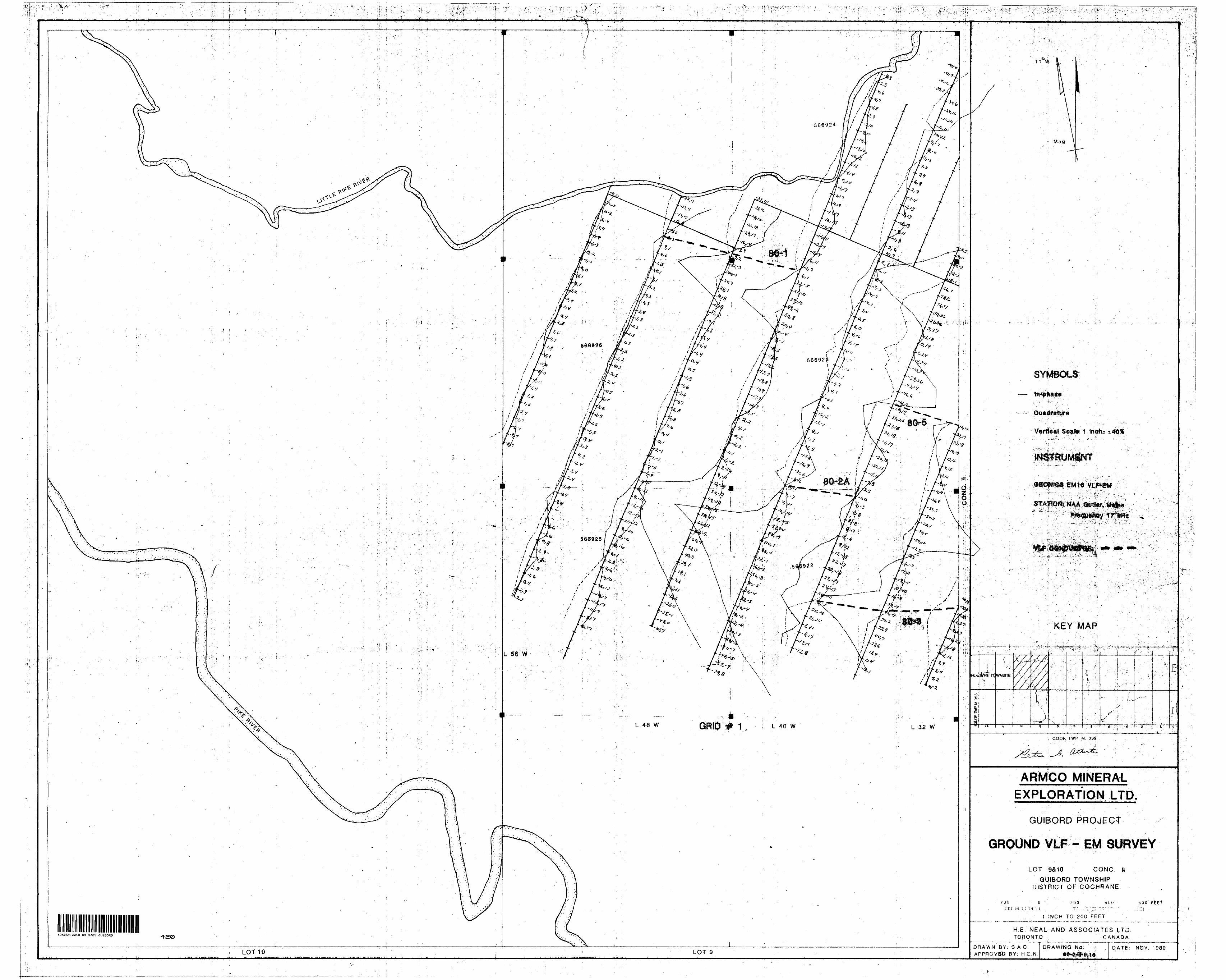
Quadrature
KEY MAP
HOt &RE TC WNSITE
: COOK TWP M. 339
ARMCO MINERAi.EXPLORATION LTD.
GUIBORD PROJECT
GROUND VLF - EM SURVEY
LOT 9&10 CONC. M
GUIBORD TOWNSHIPDISTRICT OF COCHRANE
i INCH TO 200 FEET
H.E. NEAL AND ASSOCIATES LTD,TORONTO CANADA42A08NE0e40 63.3789 GUIBORD
DRAWN BY; B,A C, APPROVED BY; H E.N.
DATE: NOV. 1980
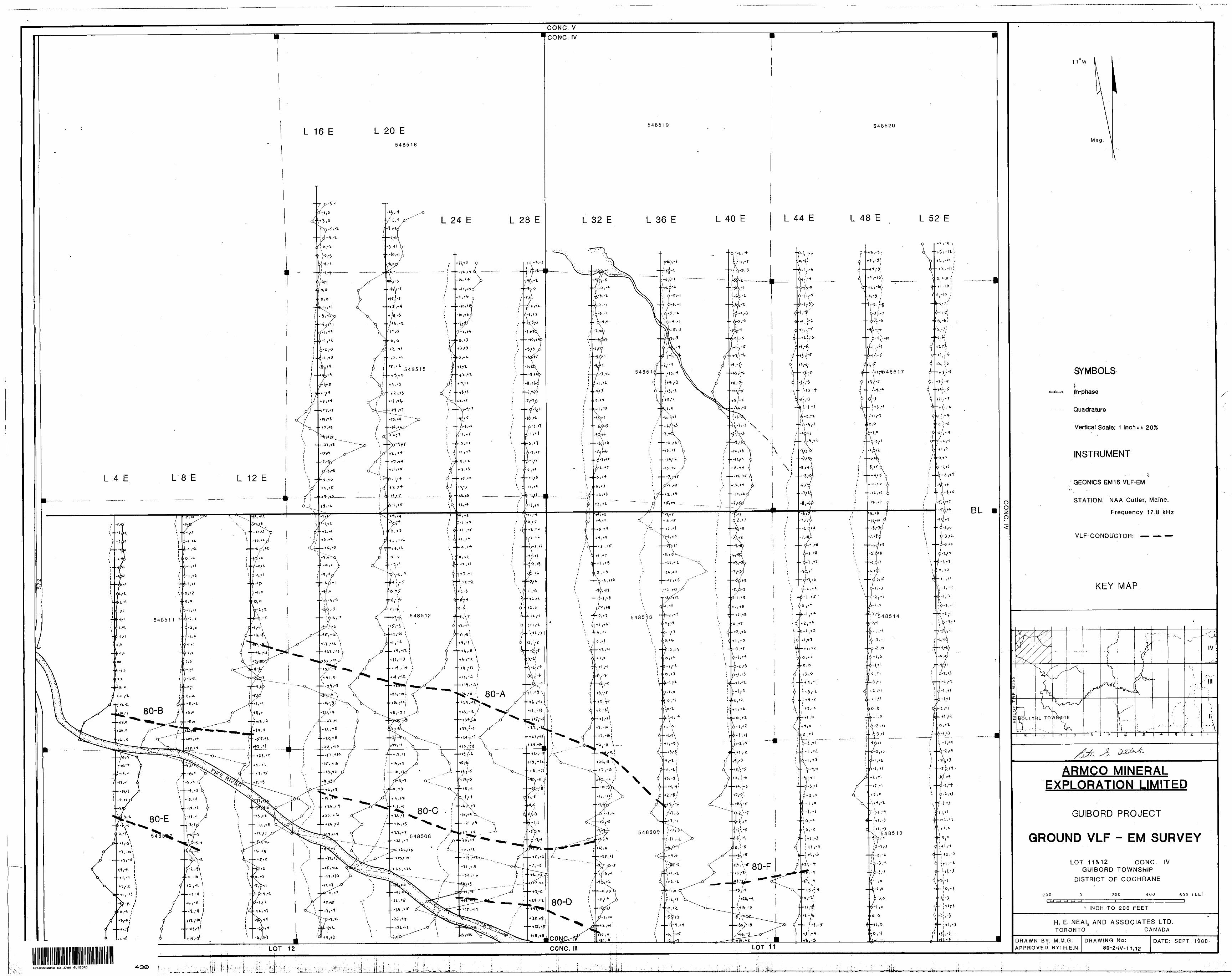
CONC. V
lrCONC. IV
Oo p ^
11 0 W
Mag,
SYMBOLS
n-phase
Quadrature
Vertical Scale; 1 inch: ± 20%
INSTRUMENT
GEONICS EM 16 VLF-EM
STATION; NAA Cutler, Maine.
Frequency 17.8 kHz
VLF-CONDUCTOR: — — —
KEY MAP
ARMCO MINERAL EXPLORATION LIMITED
GUIBORD PROJECT
GROUND VLF - EM SURVEY
LOT 11&12 CONC. IV GUIBORD TOWNSHIP
DISTRICT OF COCHRANE
200 200 400 600 FEET
t INCH TO 200 FEET
H. E. NEAL AND ASSOCIATES LTD. TORONTO . CANADA
DRAWN BY: M..M.G. APPROVED BY; H.E.N.
DRAWING No:8Q-2-IV-11J2
DATE: SEPT. 1980
42A0BNE0040 63.3789 GUIBORD