rpl: wsc, tsc, hsc 087; centrifugal chiller, … w/t/h ie 087 rev. j 09/18 rpl 7000006 / page 2...
TRANSCRIPT
Replacement Parts List No. 700000600Revision J 09/2018
To find your Daikin Applied parts distributor, call 1-800-377-2787 or visit www.DaikinApplied.com
DaikinMcQuay
Centrifugal ChillerSingle Compressor
WSC, TSC, HSC087

RPL 7000006 / Page 2Centrifugal; WSC/TSC/HSC Size 087 Rev. J 09/18
ContentsParts List Revision History.................................................................................................................................. 3Electrical Legend ................................................................................................................................................ 4Nomenclature ..................................................................................................................................................... 5 Dataplate Locations ..................................................................................................................................... 5 Unit Dataplate, Model Number- Unit, Style Number- Unit, Serial Number- Unit .......................................... 6 Model Number- Complete ......................................................................................................................7 - 11Control Box- MicroTech 200 Mounting of Unit Control Panel and Lube Box ........................................................................................... 12 Front Panel & Inside of Micro Control Door Assembly ............................................................................... 13 Interior Panel ....................................................................................................................................... 14 - 15 Sensors ...................................................................................................................................................... 16 Cables ........................................................................................................................................................ 17 Oil Pump Lube Box Assembly .................................................................................................................... 18Control Box- MicroTech II Unit Control Box Mounting ......................................................................................................................... 19 Unit Control Box Detail ....................................................................................................................... 20 - 27 Compressor Control Box Mounting ............................................................................................................ 28 Compressor Control Box Detail .......................................................................................................... 29 - 34 Cables and Sensors ............................................................................................................................ 35 - 38Starter-Units with MicroTech 200 Control Box ........................................................................................... 39 - 40Starter - Compact- Units with MicroTech II Control Box ............................................................................ 41 - 42Starter - Mini Cabinet........................................................................................................................................ 43Differential Pressure Switch ............................................................................................................................. 44Hot Gas Bypass- Until 7/02 ....................................................................................................................... 45 - 47WSC/TSC/HSC Hot Gas Bypass- 7/02 to 12/04 ....................................................................................... 48 - 49WSC/TSC Hot Gas Bypass- 1/05 to Present* .................................................................................................. 50WSC/TSC Liquid Line Thermal Expansion Valve, Ball Valve, Sight Glass, King Valve, Flanges, Gaskets, O'Rings, Pilot Valve Sensor Well ................................................................... 51 - 53HSC Liquid Line Thermal Expansion Valve, Ball Valve, Sight Glass, King Valve, Flanges, Gaskets, O'Rings, Pilot Valve Sensor Well ................................................................... 54 - 55Thermal Expansion Valve Detail ....................................................................................................................... 56Electronic Expansion Valve (Code 27= EY) ..................................................................................................... 57Condenser & Evaporator Valves ...................................................................................................................... 58Unit Insulation ................................................................................................................................................... 59Condenser Nomenclature ............................................................................................................................................. 60 Heads ......................................................................................................................................................... 61 Sight Glass, Flange, Tubes, Head Gaskets ............................................................................................... 62 Gaskets- Dish Head ............................................................................................................................ 63 - 64 Gaskets- Water Box Heads ................................................................................................................. 65 - 66Evaporator Nomenclature ............................................................................................................................................. 67 Heads ......................................................................................................................................................... 68 Sight Glass, Flange, Tubes, Head Gaskets ............................................................................................... 69 Gaskets- Dish Head ................................................................................................................................... 70 Gaskets- Water Box Heads ........................................................................................................................ 71Compressor Nomenclature ............................................................................................................................................. 72 Mounting Brackets and Hardware .............................................................................................................. 73 4- Way SA/SB Solenoid Valve & Tubing .................................................................................................... 74 Motor Drain Line, Motor Cooling Line, Liquid Injection ....................................................................... 75 - 76 Suction & Discharge Lines, Suction Victaulics, Seals, Discharge Nozzle, Flanges, Check Valve ...... 77 - 78 Section Assembly- Main Sections, O'Rings, Screws ................................................................................. 79 Front End— Inlet— Section- Vanes, Piston, Cone, Seals ......................................................................... 80 Main Gear Train .................................................................................................................................. 81 - 82 High Speed Assembly ......................................................................................................................... 83 - 84 Gears- High Speed (Pinion) & Low Speed (Bull) ....................................................................................... 85 O'Ring Kits ................................................................................................................................................. 85 15" Motor Section ................................................................................................................................ 86 - 93 20" Motor Section .............................................................................................................................. 94 - 104 Discharge Flange/O'Ring, External Flanges, Valves, Fittings and Blockoffs ........................................... 105 15" Motor Terminal Box ................................................................................................................... 106 - 109 20" Motor Terminal Box ...................................................................................................................110 - 113 Oil ...........................................................................................................................................................114Oil Pump Nomenclature ............................................................................................................................................114 16" Cast & Machined Sump Oil Pump ............................................................................................115 - 122 14" Welded Steel Sump Oil Pump ................................................................................................. 123 - 127Critical Parts List.......................................................................................................................................... CPL1
RPL 7000006 / Page 3Centrifugal; WSC/TSC/HSC Size 087 Rev. J 09/18
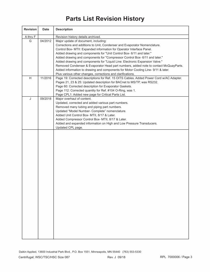
Revision Date Description
A thru F Revision history details archived. G 04/2012 Major update of document, including: Corrections and additions to Unit, Condenser and Evaporator Nomenclature. Control Box- MTII: Expanded information for Operator Interface Panel. Added drawing and components for "Unit Control Box- 6/11 and later." Added drawing and components for "Compressor Control Box- 6/11 and later." Added drawing and components for "Liquid Line: Electronic Expansion Valve." Removed Condenser & Evaporator Head part numbers, added note to contact McQuayParts. Added information to drawing and components for Motor Cooling Line- 9/11 & later. Plus various other changes, corrections and clarifications. H 11/2016 Page 19: Corrected descriptions for Ref. 15 OITS Cables. Added Power Cord w/AC Adapter. Pages 21, 23 & 25: Updated description for BACnet to MS/TP, was RS232. Page 60: Corrected description for Evaporator Gaskets. Page 112: Corrected quantity for Ref. #104 O-Ring, was 1. Page CPL1: Added new page for Critical Parts List. J 09/2018 Major overhaul of content. Updated, corrected and added various part numbers. Removed many tubing and piping part numbers. Updated “Model Number- Complete” nomenclature. Added Unit Control Box- MTII, 8/17 & Later. Added Compressor Control Box- MTII, 8/17 & Later. Added and expanded information on High and Low Pressure Transducers. Updated CPL page.
Parts List Revision History
Daikin Applied, 13600 Industrial Park Blvd., P.O. Box 1551, Minneapolis, MN 55440 (763) 553-5330

RPL 7000006 / Page 4Centrifugal; WSC/TSC/HSC Size 087 Rev. J 09/18
Electrical Legend Sch. Sym. Description Location 1M, 2M Contactor Starter 1S, 2S Energizing Contactor Starter ADI Analog/Digital Input Board MicroTech 200 Control Box AOX Analog Output Board MicroTech 200 Control Box CAP Capacitor Lube Box (MicroTech 200) or Compressor Control Box (MicroTech II) CB Circuit Breaker MicroTech 200 or MicroTech II Unit Control Box CF Condenser Flow Switch Tube Sheet Support- MicroTech II Units CHW1 Evaporator Flow Switch Tube Sheet Support- MicroTech 200 Units CR Relay MicroTech II Compressor Control Box CS01- CS10 Sensors- Compressor Controller Throughout Unit- MicroTech II (see MicroTech II section for sensor placement) CTB1, CTB2 Terminal Block Compressor Controller- MicroTech II Units CW1 Condenser Flow Switch Tube Sheet Support- MicroTech 200 Units DIST/ISO Dist. & Isolation Board MicroTech II Unit Controller EF Evaporator Flow Switch Tube Sheet Support- MicroTech II Units FVC Flux Vector Control VFD Panel (Code 29-1= V) HP High Pressure Switch MicroTech 200 Panel HR Relay MicroTech II Compressor Controller KDI Keypad/Display MicroTech 200 Panel LR Relay MicroTech II Compressor Controller MCB1 Main Control Board MicroTech 200 Panel MCR Motor Control Relay Starter Panel OBA Output Board MicroTech 200 Panel OIM Operator Interface Module VFD Panel (Code 29-1= V) OITS Operator Interface Touch Screen MicroTech II Units OL Oil Pump Overload Lube Box (MicroTech 200) or Compressor Control Panel (MicroTech II) OP Oil Pump Contactor Lube Box (MicroTech 200) or Compressor Control Panel (MicroTech II) pC02 or pC03 Main Controller MicroTech II Unit Controller PHP1 High Pressure Transducer Discharge Nozzle pLAN LAN Cable Connects MicroTech II Controllers RES Transition Resistor Starter RMI Remote Meter Interface VFD (Code 29-1= V) S00- S22 Sensor- MicroTech 200 Throughout the Unit (see MicroTech 200 section for sensor placement) SA/SB 4- Way Vane Speed Solenoid Compressor Gear Housing SC Signal Converter MicroTech 200 Control Box or MicroTech II Compressor Control Box T1, T2, T3 Main Control Transformer Starter T2 24V Control Transformer MicroTech 200 Control Box T3 18V Control Transformer MicroTech 200 Control Box TR Timing Relay Starter TRP Transition Resistance Protector Starter TSW Toggle Switch- Templifier MicroTech 200 Control Box (TSC only) US02- US10 Sensor- Unit Controller Throughout Unit- MicroTech II (see MicroTech II section for sensor placement) UTB1 Unit Control Terminal Block MicroTech II Unit Control Box VC Vane Close Switch Lube Box- MicroTech 200 Unit VR Voltage Relay Lube Box- MicroTech 200 Unit

RPL 7000006 / Page 5Centrifugal; WSC/TSC/HSC Size 087 Rev. J 09/18
NomenclatureDataplate Locations
Compressor Dataplate
Evaporator Dataplate
Unit Dataplate
Front View
End View- MicroTech 200 Units End View- MicroTech II Units
Unit Dataplate
Condenser Dataplate

RPL 7000006 / Page 6Centrifugal; WSC/TSC/HSC Size 087 Rev. J 09/18
STN U 01 05 048
Plant Identification AbbreviationSTN = Staunton
Serial Number (build sequence)
U= Unit
Year of Manufacture00= 200001= 200102= 200203= 200304= 200405= 2005
etc.
Month of Manufacture01= January02= February03= March04= April05= May06= June
07= July08= August09= September10= October11= November12= December
Serial Number- Unit
NomenclatureUnit Dataplate
WSC 087 L
Unit ModelWSC= Water- Cooled Single Compressor Centrifugal ChillerHSC= Water- Cooled Single Compressor Centrifugal Chiller with Heat Recovery CondenserTSC= Templifier, Single Compressor Centrifugal
Impeller Size087= 8.7" Diameter
Impeller typeL, M
Model Number- Unit
E 923456 010
6- Digit G.O. Number G.O. Item Number
Style Number- Unit
Always "E"
Units w/ Free Standing Starter

RPL 7000006 / Page 7Centrifugal; WSC/TSC/HSC Size 087 Rev. J 09/18
1. Model TypeWSC= Water Cooled Centrifugal ChillerHSC= Water Cooled Heat Recovery Centrifugal ChillerTSC= Centrifugal Templifier
2. Compressor Size/Impeller Type087 (8.7" impeller)087L, 087M
3. Gear Ratio Code (speed code)AQ, AR, AS, AT, AU, AV, AW, A2, AY, AZ, BA, BB, BC, BD, BE, BF, BG, BH
4. Motor Horsepower/Voltagefirst 2 digits= horsepower, third digit= voltage16= 160HP 18= 185HP 19= 190HP 21= 210HP 23= 230HP 25= 250HP 29= 290HP 32= 320HP 35= 350HP 40= 400HP 41= 410HP 47= 470HP 49= 490HP 50= 500HP 57= 570HP 58= 580HP 65= 650HP 66= 660HP third digit= voltage 60 Hz. CodesN= 200V B= 208V P= 220V V= 230V W= 240V U= 380V 4= 400V A= 440V R= 460V S= 480V D= 575V 3= 2300V M= 2400V C= 3300V L= 4160V T= 4600V 2= 6600V Q= 13200V Z= 13800V third digit= voltage 50 Hz. CodesE= 220V Y= 346V F= 380V G= 400V K= 415V H= 440V 7= 690V 6= 3000V J= 3300V 8= 6000V 9= 6600V 5= 10000V 1= 11000V
5. Refrigerant Contamination ProtectionY= None
6. Sound ControlL= Liquid Injection
7. Compressor Revision LevelA= Rev. Level A B= Rev. Level B C= Rev. Level C D= Rev. Level D
8. Evaporator DescriptionE2609= Standard Evaporator, 26" Diameter/9' Long E3009= Standard Evaporator, 30" Diameter/9' Long E3609= Standard Evaporator, 36" Diameter/9' Long E2612= Standard Evaporator, 26" Diameter/12' Long E3012= Standard Evaporator, 30" Diameter/12' Long E3612= Standard Evaporator, 36" Diameter/12' Long
9. Evaporator Tube Descriptionfirst digit= Tube Count/ second digit= Tube typeTube Count26” diameter: B= 226 C= 178 J= 123 (3/4”) + 57 (1”) K= 99 (3/4”) + 47 (1”) 30” diameter: B= 300 C= 262 J= 155 (3/4”) + 90 (1”) K= 127 (3/4”) + 81 (1”) 36" diameter: B= 488 C= 414 D= 352 J= 244 (3/4”) + 136 (1”) K= 215 (3/4”) + 108 (1”) M= 179 (3/4”) + 95 (1”)Tube TypeE= Turbo EFP .025 Wall; F= Turbo EFP .028 Wall; Q= Turbo EFP .035 Wall
10. Evaporator Head Descriptionfirst digit= Number of Water Passes: 1, 2, 3second digit= Inlet Nozzle Location: L= Left R= Rightthird digit= Nozzle Type: A= Grooved; B= Flanged; C= Marine Box- Grooved; E= Marine Box- Flanged
WSC 087M AZ 40B Y L D E3612 BE 2LA B4 0450 CC Y A C3012 BLYY Code: 1 2 3 4 5 6 7 8 9 10 11 12 13 14 15 16 17
NomenclatureModel Number- Complete
2LAYYY D4 1370 CCYY YY A A 134 196 BY 2LEMBA 21YY2YYY 0325 H H2 B Code: 18 19 20 21 22 23 24 25 26 27 28 29 30 31 32 33
1 1 B Y S Y 1 A A 0500 U B C Y Y Y Y 1 Y Y W Code: 34 35 36 37 38 39 40 41 42 43 44 45 46 47 48 49 50 51 52 53 54
RPL 7000006 / Page 8Centrifugal; WSC/TSC/HSC Size 087 Rev. J 09/18
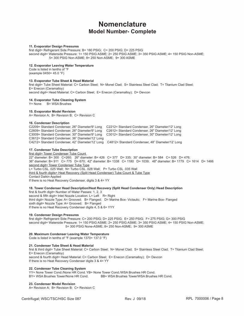
11. Evaporator Design Pressuresfirst digit= Refrigerant Side Pressure: B= 180 PSIG; C= 200 PSIG; D= 225 PSIGsecond digit= Waterside Pressure: 1= 150 PSIG ASME; 2= 250 PSIG ASME; 3= 350 PSIG ASME; 4= 150 PSIG Non-ASME; 5= 300 PSIG Non-ASME; 8= 250 Non-ASME; 9= 300 ASME
12. Evaporator Leaving Water TemperatureCode is listed in tenths of °F(example 0450= 45.0 °F)
13. Evaporator Tube Sheet & Head Materialfirst digit= Tube Sheet Material: C= Carbon Steel; N= Monel Clad; S= Stainless Steel Clad; T= Titanium Clad Steel; E= Enecon (Ceramalloy)second digit= Head Material: C= Carbon Steel; E= Enecon (Ceramalloy); D= Devcon
14. Evaporator Tube Cleaning SystemY= None B= WSA Brushes
15. Evaporator Model RevisionA= Revision A; B= Revision B; C= Revision C
16. Condenser DescriptionC2209= Standard Condenser, 26" Diameter/9' Long C2212= Standard Condenser, 26" Diameter/12' LongC2609= Standard Condenser, 26" Diameter/9' Long C2612= Standard Condenser, 26" Diameter/12' LongC3009= Standard Condenser, 30" Diameter/9' Long C3012= Standard Condenser, 30" Diameter/12' LongC3612= Standard Condenser, 36” Diameter/12’ LongC4212= Standard Condenser, 42” Diameter/12’ Long C4812= Standard Condenser, 48” Diameter/12’ Long
17. Condenser Tube Descriptionfirst digit= Tower Condenser Tube Count 22" diameter: B= 300 C=260; 26" diameter: B= 426 C= 377 D= 335; 30” diameter: B= 584 C= 526 D= 476; 36" diameter: B= 911 C= 775 D= 670; 42" diameter: B= 1338 C= 1180 D= 1039; 48" diameter: B= 1779 C= 1614 D= 1466second digit= Tower Condenser Tube Type L= Turbo CSL .025 Wall; N= Turbo CSL .028 Wall; P= Turbo CSL .035 Wallthird & fourth digits= Heat Recovery (Split Head Condenser) Tube Count & Tube TypeContact Daikin AppliedIf there is no Heat Recovery Condenser, digits 3 & 4= YY
18. Tower Condenser Head Description/Heat Recovery (Split Head Condenser Only) Head Descriptionfirst & fourth digit= Number of Water Passes: 1, 2, 3second & fifth digit= Inlet Nozzle Location: L= Left R= Rightthird digit= Nozzle Type: A= Grooved; B= Flanged; D= Marine Box- Victaulic; F= Marine Box- Flangedsixth digit= Nozzle Type: A= Grooved; B= FlangedIf there is no Heat Recovery Condenser digits 4, 5 & 6= YYY
19. Condenser Design Pressuresfirst digit= Refrigerant Side Pressure: C= 200 PSIG; D= 225 PSIG; E= 250 PSIG; F= 275 PSIG; G= 300 PSIGsecond digit= Waterside Pressure: 1= 150 PSIG ASME; 2= 250 PSIG ASME; 3= 350 PSIG ASME; 4= 150 PSIG Non-ASME; 5= 300 PSIG None-ASME; 8= 250 Non-ASME; 9= 300 ASME
20. Maximum Condenser Leaving Water TemperatureCode is listed in tenths of °F (example 1370= 137.0 °F)
21. Condenser Tube Sheet & Head Materialfirst & third digit= Tube Sheet Material: C= Carbon Steel; N= Monel Clad; S= Stainless Steel Clad; T= Titanium Clad Steel;E= Enecon (Ceramalloy)second & fourth digit= Head Material: C= Carbon Steel; E= Enecon (Ceramalloy); D= DevconIf there is no Heat Recovery Condenser digits 3 & 4= YY
22. Condenser Tube Cleaning SystemYY= None Tower Cond./None HR Cond. YB= None Tower Cond./WSA Brushes HR Cond.BY= WSA Brushes Tower/None HR Cond. BB= WSA Brushes Tower/WSA Brushes HR Cond.
23. Condenser Model RevisionA= Revision A; B= Revision B; C= Revision C
NomenclatureModel Number- Complete

RPL 7000006 / Page 9Centrifugal; WSC/TSC/HSC Size 087 Rev. J 09/18
24. Pressure Vessel CodeA= ASME; J= Australian; S= Swiss; P= Chinese; K= Korean; 0= CRN British Columbia 7= CRN Nova Scotia1= CRN Alberta 8= CRN Prince Edward Island2= CRN Saskatchewan 9= CRN Newfoundland3= CRN Manitoba F= CRN Nunavut4= CRN Ontario W= CRN Northwest Territories5= CRN Quebec U= CRN Yukon6= CRN New Brunswick
25. Refrigerant Type134= Refrigerant 134a
26. Refrigerant WeightTotal weight divided by 10 rounded to next whole number (example: 1712/10= 172)
27. Main Expansion Valve/ Pilot Valvefirst digit= Main Expansion Valve: E= 650 ton EEXVsecond digit= Pilot Valve: T= Templifier; Y= None
28. Controller OptionsMicroTech 200first digit= Control Type: M= MicroTechsecond digit= Sensor Functions: A= Outdoor Air (OA) Thermistor S20; B= OA and HR; H= Heat Recovery (HR) Thermistors S21/S22third digit= Language: E= English Language/English Units; M= English Language/Metric Units; J= Japanese; C= Chinesefourth digit= Instruments: M= Modem; Y= Nonefifth digit= Special Functions: A= Analog Outputs; B= Analog Outputs & Signal Converter; S= Signal Convertersixth digit= Enclosure: A= NEMA 1; B= NEMA 4; C= NEMA 12MicroTech IIfirst digit= Control Type: 2= MicroTech IIsecond digit= Size: L= Large; H= Heat Recoverythird digit= Language: E= English Languagefourth digit= Instruments: M= Modem; Y= Nonefifth digit= Communications: B= BACnet MS/TP; E= BACnet IP; L= LonMark; M= MODBUS; P= Serial Port w/modem; S= Serial Port (RS232); Y= Nonesixth digit= Enclosure: A= NEMA 1; B= NEMA4/NEMA12
29. Starter Optionsfirst digit= Starter Type: 2= Wye-Delta Closed; 3= Across-The-Line; 4= Auto Transformer; 5= Primary Reactor; 6= Solid State V= Variable Frequency Drivesecond digit= Enclosure: Y= By Others Free Standing- 5= 90” X 36” X 21”; 7= Med/High Voltage 90” X 36” X 30”; 9= Med/High Voltage 90” X 72” X 30”; B= VFD Cab #1 (48”); C= VFD Cab #2 (72”); U= VFD Cab #3 (77”); L= VFD Unit Mounted- D= VFD Cab #1 (48”); E= VFD Cab #2 (72”); G= Mini Cab; M= VFD; N= VFD on Condenser Field Mounted- S= VFD w/brackets Cab #1 (48”); T= VFD w/brackets Cab #2 (72”) Terminal Mounted- R= 72” High; Q= 72” High x 2third digit= VFD Cooling Mode: Y= None; D= DRC/ABB Air Cooled; P= PowerFlex 755 Air Cooled; W= Water Cooledfourth digit= Disconnect: Y= Nonefifth digit= Surge Protection Capacitor: 2= Surge Capacitor mounted in Compressor Motor Terminal Box; S= Surge Capacitor mounted in Starter Box; Y= Nonesixth digit= Phase Loss/Rotation Protection: Y= Noneseventh digit= Ground Fault Protection: Y= None; G= Ground Fault Protection Moduleeighth digit= Meters: A= Ammeter Module; F= Full Metering Module; Y= None
30. Rated Load AmpsActual RLA
31. Hot Gas BypassH= Hot Gas BypassY= None
NomenclatureModel Number- Complete
RPL 7000006 / Page 10Centrifugal; WSC/TSC/HSC Size 087 Rev. J 09/18
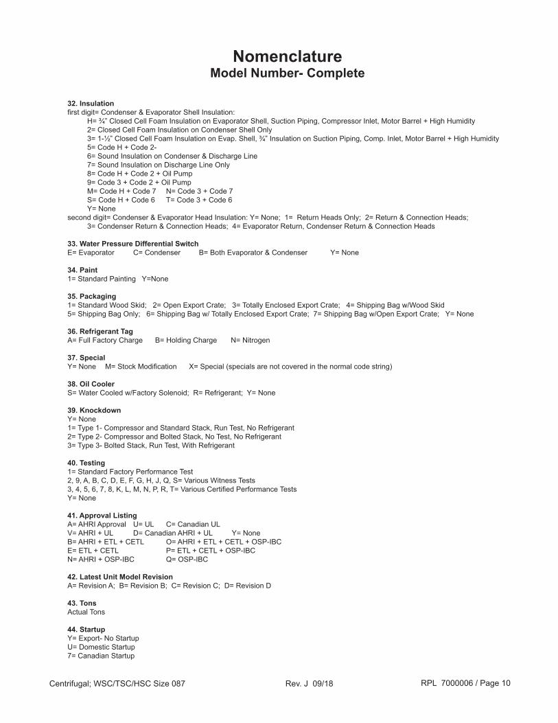
32. Insulationfirst digit= Condenser & Evaporator Shell Insulation: H= ¾” Closed Cell Foam Insulation on Evaporator Shell, Suction Piping, Compressor Inlet, Motor Barrel + High Humidity 2= Closed Cell Foam Insulation on Condenser Shell Only 3= 1-½” Closed Cell Foam Insulation on Evap. Shell, ¾” Insulation on Suction Piping, Comp. Inlet, Motor Barrel + High Humidity 5= Code H + Code 2- 6= Sound Insulation on Condenser & Discharge Line 7= Sound Insulation on Discharge Line Only 8= Code H + Code 2 + Oil Pump 9= Code 3 + Code 2 + Oil Pump M= Code H + Code 7 N= Code 3 + Code 7 S= Code H + Code 6 T= Code 3 + Code 6 Y= Nonesecond digit= Condenser & Evaporator Head Insulation: Y= None; 1= Return Heads Only; 2= Return & Connection Heads; 3= Condenser Return & Connection Heads; 4= Evaporator Return, Condenser Return & Connection Heads
33. Water Pressure Differential SwitchE= Evaporator C= Condenser B= Both Evaporator & Condenser Y= None
34. Paint1= Standard Painting Y=None
35. Packaging1= Standard Wood Skid; 2= Open Export Crate; 3= Totally Enclosed Export Crate; 4= Shipping Bag w/Wood Skid5= Shipping Bag Only; 6= Shipping Bag w/ Totally Enclosed Export Crate; 7= Shipping Bag w/Open Export Crate; Y= None
36. Refrigerant TagA= Full Factory Charge B= Holding Charge N= Nitrogen
37. SpecialY= None M= Stock Modification X= Special (specials are not covered in the normal code string)
38. Oil CoolerS= Water Cooled w/Factory Solenoid; R= Refrigerant; Y= None
39. KnockdownY= None 1= Type 1- Compressor and Standard Stack, Run Test, No Refrigerant2= Type 2- Compressor and Bolted Stack, No Test, No Refrigerant3= Type 3- Bolted Stack, Run Test, With Refrigerant
40. Testing1= Standard Factory Performance Test2, 9, A, B, C, D, E, F, G, H, J, Q, S= Various Witness Tests3, 4, 5, 6, 7, 8, K, L, M, N, P, R, T= Various Certified Performance TestsY= None
41. Approval ListingA= AHRI Approval U= UL C= Canadian ULV= AHRI + UL D= Canadian AHRI + UL Y= NoneB= AHRI + ETL + CETL O= AHRI + ETL + CETL + OSP-IBCE= ETL + CETL P= ETL + CETL + OSP-IBCN= AHRI + OSP-IBC Q= OSP-IBC
42. Latest Unit Model RevisionA= Revision A; B= Revision B; C= Revision C; D= Revision D
43. TonsActual Tons
44. StartupY= Export- No StartupU= Domestic Startup7= Canadian Startup
NomenclatureModel Number- Complete
RPL 7000006 / Page 11Centrifugal; WSC/TSC/HSC Size 087 Rev. J 09/18
NomenclatureModel Number- Complete
45. Labor WarrantyC= Entire Unit Parts & Compressor-only LaborP= Entire Unit Parts OnlyY= Entire Unit Parts and Labor
46. Extended Warranties1= Year 2- Entire Unit parts + Labor; Years 3 thru 5- Compressor parts + Labor 2= Year 2- Entire Unit parts + Labor; Years 3 thru 5- Compressor parts only 3= Year 2- Entire Unit parts only; Years 3 thru 5- Compressor parts only Y= None
These Codes apply to Entire Unit Including Starter: C= Extended 1 year parts; D= Extended 1 year parts + Labor; E= Extended 2 year parts; F= Extended 2 year parts + Labor; G= Extended 3 year parts; H= Extended 3 year parts + Labor; J= Extended 4 year parts; K= Extended 4 year parts + Labor; 4= Extended 5 year parts; 5= Extended 5 year parts + Labor; 6= Extended 9 year parts; 7= Extended 9 year parts + Labor
These Codes apply to Compressor/Drive Train Only: L= Extended 1 year parts; M= Extended 1 year parts + Labor; N= Extended 2 year parts; O= Extended 2 year parts + Labor; P= Extended 3 year parts; Q= Extended 3 year parts + Labor; R= Extended 4 year parts; S= Extended 4 year parts + Labor; T= Extended 5 year parts; U= Extended 5 year parts + Labor; V= Extended 9 year parts; W= Extended 9 year parts + Labor
47. Always Y
48. Always Y
49. Always Y
50. MotorA= A.O. Smith C= YYZM= Ram R= Reliance
51. Refrigerant Warranty0 thru 5= actual number of years
52. Delayed Warranty StartY= None D= 12-24: Additional Months 6A= 12-18: Additional Months 0 E= 12-26: Additional Months 8B= 12-20: Additional Months 2 F= 12-28: Additional Months 10C= 12-22: Additional Months 4 G= 12-30: Additional Months 12
53. MiscellaneousY= StandardC= Compressor Kit onlyB= BOM onlyM=Stock ModificationR= Retrofit Compressor Kit only
54. Coolant RatingW= Water on Evaporator and CondenserG= Non-water on Evaporator, Condenser, or both

RPL 7000006 / Page 12Centrifugal; WSC/TSC/HSC Size 087 Rev. J 09/18
Control Box- MicroTech 200Mounting of Unit Control Panel and Lube Box
Ref. Description Part Qty. No. Number 201 Control Box- MicroTech 200 1
202 Screw .37 x .75 735033230 4 203 Washer- Plain .375 ZPS 040500316 4 204 Washer- Lock .375 ZPS 048164812 4 260 Lube Box- 60 Hz. 1 330006601 1 Lube Box- 50 Hz. 1 330006602 1 280 Screw .25- 20 X.75 040499024 4 282 Washer- Lock .25 ZPS 048164808 4 283 Nut- Hex .25- 20 040499901 4 301 Bracket- Control Box 070013253 2
280
283282
1 See following pages for component detail.
260201
301202
203 204
Oil Pump Bracket
Shown with Lube Box Cover and Components Panel
Removed
RPL 7000006 / Page 13Centrifugal; WSC/TSC/HSC Size 087 Rev. J 09/18
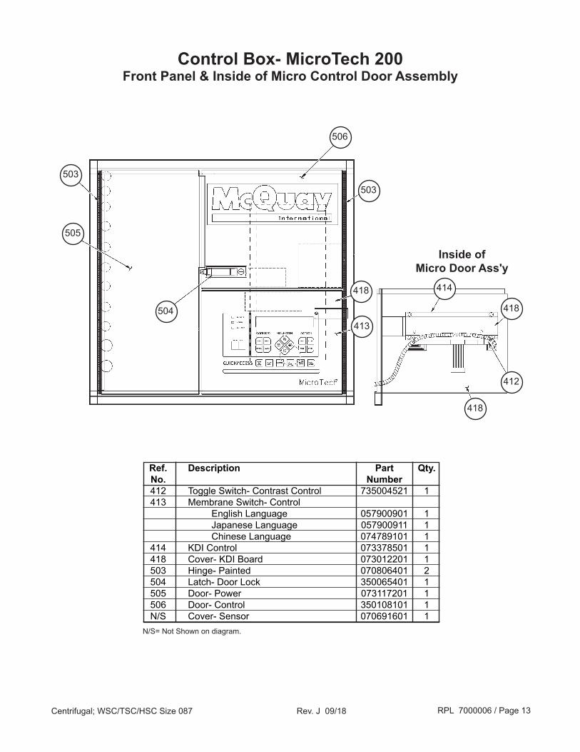
Control Box- MicroTech 200Front Panel & Inside of Micro Control Door Assembly
503
505
504
506
503
418
413
Ref. Description Part Qty. No. Number 412 Toggle Switch- Contrast Control 735004521 1 413 Membrane Switch- Control English Language 057900901 1 Japanese Language 057900911 1 Chinese Language 074789101 1 414 KDI Control 073378501 1 418 Cover- KDI Board 073012201 1 503 Hinge- Painted 070806401 2 504 Latch- Door Lock 350065401 1 505 Door- Power 073117201 1 506 Door- Control 350108101 1 N/S Cover- Sensor 070691601 1N/S= Not Shown on diagram.
Inside of Micro Door Ass'y
414
418
412
418

RPL 7000006 / Page 14Centrifugal; WSC/TSC/HSC Size 087 Rev. J 09/18
Control Box- MicroTech 200Interior Panel
161 162
507508
509 518
Micro Door Ass'y
(see previous page)
111
142
154160
152159
163
158
130 156 150 155
113125126
107
157
125126
108
109
102
103104
524 525184182
183
Modem Detail
971 972 974
970976
523
143
106
522
511See Detail above

RPL 7000006 / Page 15Centrifugal; WSC/TSC/HSC Size 087 Rev. J 09/18
Control Box- MicroTech 200Interior Panel
Ref. Description Specification Part Qty. No. Number 102 Main Controller- MicroTech M280 065487350 1 1 103 ADI Board until 3/03 065816003 1 ADI Board 3/03 and later 330325401 1 104 Mount- ADI Board 055727206 1 106 Cord Set- PCB Interface 049265103 1 107 Ribbon Cable 50C 18/24 OB 049265208 1 108 Ribbon Cable 50C 3" 072941801 2 109 Clip, Flat- Cable 049766201 2 111 Terminal Block AD1 AD2 072993901 2 113 Transformer- Control .03 KVA 24/18V 046738114 1 125 Terminal Block 9 Pole 1 Row 065499909 11 126 Cover- Terminal Block 065500009 11 130 Bracket- Terminal Block 073212801 3 142 Board- Signal Converter SC 049264901 1 143 Spacer- Signal Converter 048166702 4 150 Toggle Switch (TSC Templifier Only) TSW 735004521 1 152 Output Board 24 SM 072986401 1 154 Board- Guardistor 067113001 1 155 Circuit Breaker 3A 1P 735073301 1 156 Transformer 50 VA 120/24V 060630801 1 157 Terminal Block Unit & Field 073118801 1 158 Varistor 30 VRMS 049759701 1 159 Ferrules- Dual Wires 8 mm 073008204 19 160 Mount- Circuit Board 055727207 1 161 Socket, Relay- High Pressure 735003105 1 162 Relay- High Pressure HP 735020820 1 163 Relay- Output Board 073202501 19 182 AOX Board 4 Channel 066794804 1 183 Mount- AOX Board 055727203 1 184 Cord Set 9" 28AWG 065499702 1 507 Bracket- Magnetic Latch 073212701 1 508 Magnetic Latch 034905200 1 509 Fastener- Magnetic Latch 034905000 1 511 Gasket .12 X .75 070199209 1 518 Bushing- Snap In 2.00" 030188500 1 522 Bushing- Snap In 1.50" 036561900 1 523 Plug- Terminal Housing 4 Pin Female 049264502 1 524 Plug- Terminal Housing 6 Pin Female 049264501 2 525 Terminal- Socket 24-18 AWG 049264702 12 970 Modem 14.4 BAUD 063585005 1 971 Cord Set- Modem 073372702 1 972 Gasket .25 X .70 070199207 1 974 Bracket- Modem Mounting 073043505 1 976 Bracket- Vertical, Modem 073014701 11 Controller needs to be programmed.The Unit serial number is required to properly program the controller.
RPL 7000006 / Page 16Centrifugal; WSC/TSC/HSC Size 087 Rev. J 09/18
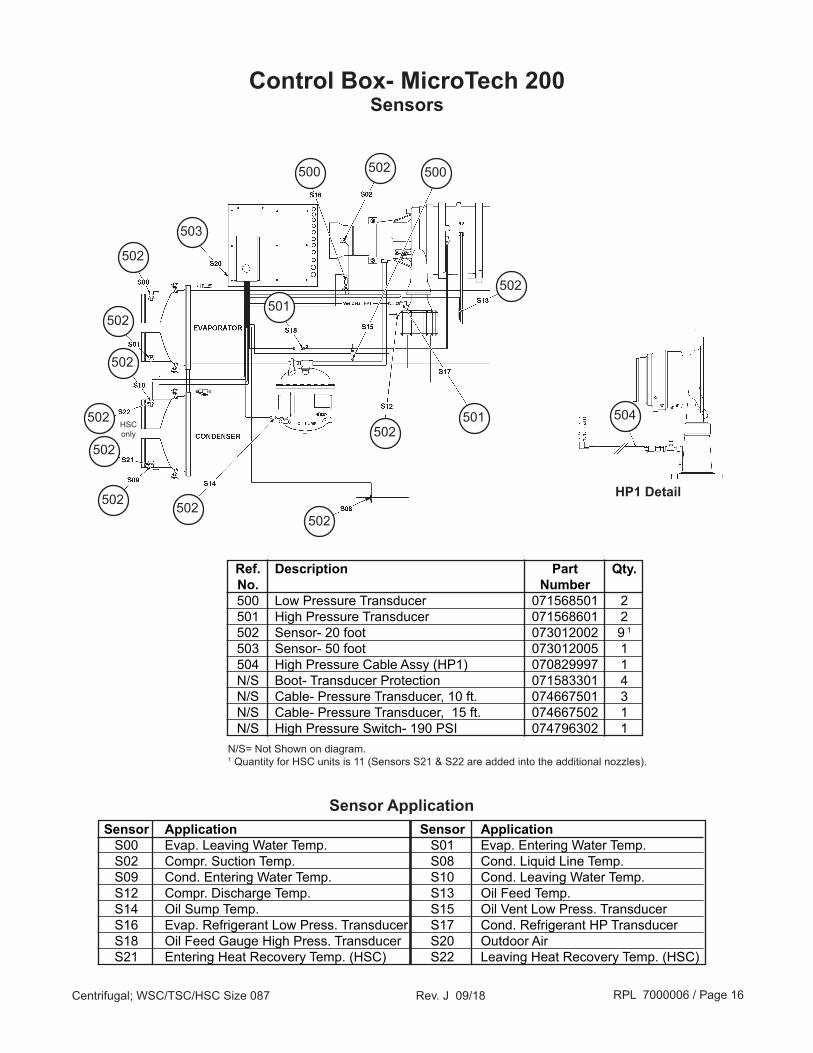
Control Box- MicroTech 200Sensors
502
503
500
501
Ref. Description Part Qty. No. Number 500 Low Pressure Transducer 071568501 2 501 High Pressure Transducer 071568601 2 502 Sensor- 20 foot 073012002 9 1
503 Sensor- 50 foot 073012005 1 504 High Pressure Cable Assy (HP1) 070829997 1 N/S Boot- Transducer Protection 071583301 4 N/S Cable- Pressure Transducer, 10 ft. 074667501 3 N/S Cable- Pressure Transducer, 15 ft. 074667502 1 N/S High Pressure Switch- 190 PSI 074796302 1N/S= Not Shown on diagram.1 Quantity for HSC units is 11 (Sensors S21 & S22 are added into the additional nozzles).
Sensor Application Sensor Application S00 Evap. Leaving Water Temp. S01 Evap. Entering Water Temp. S02 Compr. Suction Temp. S08 Cond. Liquid Line Temp. S09 Cond. Entering Water Temp. S10 Cond. Leaving Water Temp. S12 Compr. Discharge Temp. S13 Oil Feed Temp. S14 Oil Sump Temp. S15 Oil Vent Low Press. Transducer S16 Evap. Refrigerant Low Press. Transducer S17 Cond. Refrigerant HP Transducer S18 Oil Feed Gauge High Press. Transducer S20 Outdoor Air S21 Entering Heat Recovery Temp. (HSC) S22 Leaving Heat Recovery Temp. (HSC)
Sensor Application
HP1 Detail
501
502
502
502
502
502
502
502
502
502
502
500
504HSC only

RPL 7000006 / Page 17Centrifugal; WSC/TSC/HSC Size 087 Rev. J 09/18
Control Box- MicroTech 200Cables
Ref. Description Part Qty. No. Number 401 Cable- Lube Box to Control Box 200 330006798 1 403 Cable- Lube Box to Oil Pump 330006731 1 405 Cable- Oil Cooler Solenoid 330006751 1 406 Cable- Liquid Injection 070813333 1 408 Cable- Hot Gas Valve 070813552 1 411 Cable- Evaporator DPS 071543664 1 412 Cable- Condenser DPS 071543663 1 866 Cable- 20" Motor Terminal Box 070829971 1 888 Cable- Guardistor 070829989 1
Control Box
408411
412
406
866
888
403
405
401

RPL 7000006 / Page 18Centrifugal; WSC/TSC/HSC Size 087 Rev. J 09/18
Ref. Sch. Description Part Qty. No. Sym. Number Complete Lube Box Assembly 60 Hz. Units 330006601 50 Hz. Units 330006602 1 Box- Lube 071467601 1 2 Panel 071435301 1 2A Screw #10 x .37 735032742 5 3 OP Contactor- Oil Pump Motor 072997402 1 3A Screw #8 x .75 735032732 2 4 OL Overload 735021501 1 4A Screw #8 x .37 735032729 2 5 Heater- Overload 735021577 1 6 Terminal Block 073014801 1 6A Screw #4 x .63 073208301 2 7 CAP Capacitor 60 Hz. Units 35 MFD @ 370V 735067401 1 50 Hz. Units 60 MFD @ 370V 735067403 1 8 Strap- Capacitor 071435401 1 8A Screw #10 x .37 735032742 2
Control Box- MicroTech 200Oil Pump Lube Box Assembly
23
1
6 6A
7
8
3A2A
8A
4
54A

RPL 7000006 / Page 19Centrifugal; WSC/TSC/HSC Size 087 Rev. J 09/18
Control Box- MicroTech IIUnit Control Box Mounting
24
19
22
2321
18 27
22
24
22
23
26
15
19
18
16
25
NOTE: Original design Operator Interface Panel shown. Mounting hardware is the same for all panels.
Ref. Description Specification Part Qty. No. Number 15 Operator Interface Panel (OITS), Original until 5/05* 071858001 1 Cable, 7-wire single, Original until 5/05* 330367901 1 Connector Only, Original until 5/05* 330332007 1 15 Operator Interface Panel w/cables, 12” Beige 5/05 & later* 330277501 1 15 Operator Interface Panel w/VGA & Serial cables, 15” Beige 5/05 & later* 330276501 1 15 Operator Interface Panel w/ VGA & Serial cables, 15” Black 5/05 & later* 330276502 1 Cable, 12V DC Power w/4 Pin Molex & 2 Plugs all 5/05 & later* 300040768 1 Cable, Serial all 5/05 & later* 300043345 1 Cable Kit (includes VGA & Serial cables) all 5/05 & later* 300043289 1 Power Cord w/AC Adapter all 5/05 & later* 300053912 1
16 Support Arm Assy, Beige (includes swivel pin, washers, & nut) 330815401 1 16 Support Arm Assy, Black (includes swivel pin, washers, & nut) 330815411 1
18 Block- Mount 330406501 2 19 Shelf 330329601 1 21 Screw 040499041 4 22 Washer- Plain 040500316 12 23 Washer- Lock Spring 048164812 8 24 Washer- Lock 040500213 12 25 Washer- Nylon 330366101 4 26 Nut 040499906 4 27 Screw 040499040 4* For units built 1/05 to 5/05, check unit to verify which panel is installed. Original panel had single cable, later panels have 3 cables.
RPL 7000006 / Page 20Centrifugal; WSC/TSC/HSC Size 087 Rev. J 09/18
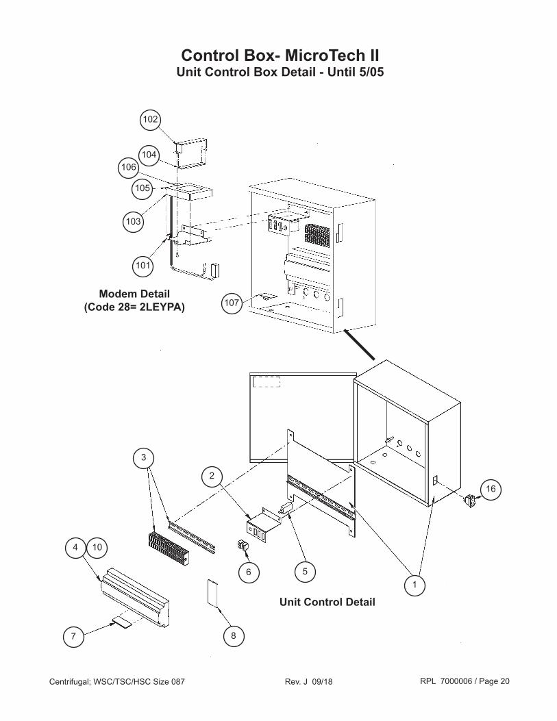
Control Box- MicroTech IIUnit Control Box Detail - Until 5/05
102
104106
105
103
101
107
16
15
2
6
3
8
4
7
10
Modem Detail(Code 28= 2LEYPA)
Unit Control Detail
RPL 7000006 / Page 21Centrifugal; WSC/TSC/HSC Size 087 Rev. J 09/18
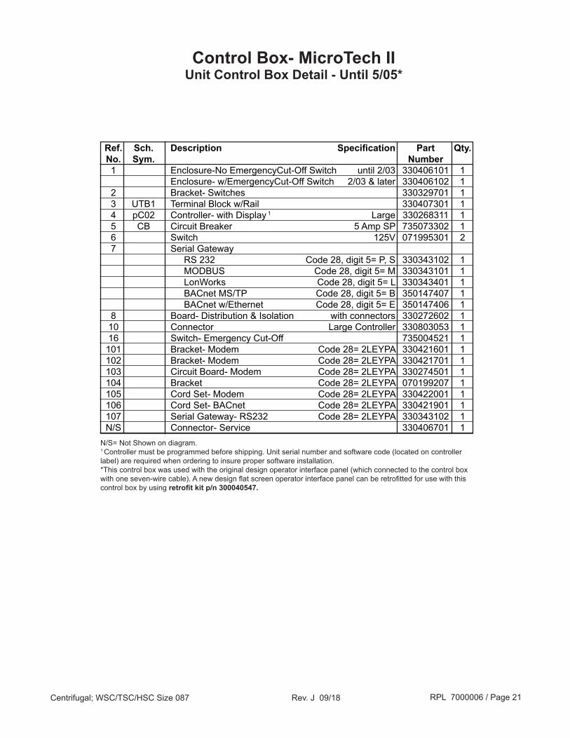
N/S= Not Shown on diagram.1 Controller must be programmed before shipping. Unit serial number and software code (located on controller label) are required when ordering to insure proper software installation. *This control box was used with the original design operator interface panel (which connected to the control box with one seven-wire cable). A new design flat screen operator interface panel can be retrofitted for use with this control box by using retrofit kit p/n 300040547.
Control Box- MicroTech IIUnit Control Box Detail - Until 5/05*
Ref. Sch. Description Specification Part Qty. No. Sym. Number 1 Enclosure-No EmergencyCut-Off Switch until 2/03 330406101 1 Enclosure- w/EmergencyCut-Off Switch 2/03 & later 330406102 1 2 Bracket- Switches 330329701 1 3 UTB1 Terminal Block w/Rail 330407301 1 4 pC02 Controller- with Display 1 Large 330268311 1 5 CB Circuit Breaker 5 Amp SP 735073302 1 6 Switch 125V 071995301 2 7 Serial Gateway RS 232 Code 28, digit 5= P, S 330343102 1 MODBUS Code 28, digit 5= M 330343101 1 LonWorks Code 28, digit 5= L 330343401 1 BACnet MS/TP Code 28, digit 5= B 350147407 1 BACnet w/Ethernet Code 28, digit 5= E 350147406 1 8 Board- Distribution & Isolation with connectors 330272602 1 10 Connector Large Controller 330803053 1 16 Switch- Emergency Cut-Off 735004521 1 101 Bracket- Modem Code 28= 2LEYPA 330421601 1 102 Bracket- Modem Code 28= 2LEYPA 330421701 1 103 Circuit Board- Modem Code 28= 2LEYPA 330274501 1 104 Bracket Code 28= 2LEYPA 070199207 1 105 Cord Set- Modem Code 28= 2LEYPA 330422001 1 106 Cord Set- BACnet Code 28= 2LEYPA 330421901 1 107 Serial Gateway- RS232 Code 28= 2LEYPA 330343102 1 N/S Connector- Service 330406701 1

RPL 7000006 / Page 22Centrifugal; WSC/TSC/HSC Size 087 Rev. J 09/18
12
22
24 23
16
Control Box- MicroTech IIUnit Control Box Detail- 5/05 to 6/11
7
10
2
8
3
5 6
HGBP Electronic Expansion Valve Driver & Transformer Detail
4
17

RPL 7000006 / Page 23Centrifugal; WSC/TSC/HSC Size 087 Rev. J 09/18
N/S= Not Shown on diagram.1 Controller must be programmed before shipping. Unit serial number and software code (located on controller label) are required when ordering to insure proper software installation.
Ref. Sch. Description Specification Part Qty. No. Sym. Number 2 Bracket- Switches 330329701 1 3 UTB1 Terminal Block w/Rail 330407301 1 4 pC02 Controller- with Display 1 330268311 1 5 CB Circuit Breaker 5 Amp SP 735073302 1 6 Switch 125V 071995301 2 7 Serial Gateway RS 232 Code 28, digit 5= P, S 330343102 1 MODBUS Code 28, digit 5= M 330343101 1 LonWorks Code 28, digit 5= L 330343401 1 BACnet MS/TP Code 28, digit 5= B 350147407 1 BACnet w/Ethernet Code 28, digit 5= E 350147406 1 8 Relay 24V 330720910 1 10 Connector 330803053 1 12 Holder- Relay 330720911 1 16 Switch- Emergency Cut-Off 735004521 1 17 UCM Board- Universal Communications 330275202 1 22 PC Assy- Single Board PC 330277301 1 23 Driver- HGBP Electronic Expansion Valve 330277803 1 24 Transformer- Isolation 15VA 330277601 1 N/S Connector- Service 330406701 1
Control Box- MicroTech IIUnit Control Box Detail- 5/05 to 6/11

RPL 7000006 / Page 24Centrifugal; WSC/TSC/HSC Size 087 Rev. J 09/18
Control Box- MicroTech IIUnit Control Box Detail- 6/11 to 8/17*
24
22
23
Controller
PC
6
12
17
4
7
103
2
5
16
8
* For units built in August 2017, contact Daikin Applied.

RPL 7000006 / Page 25Centrifugal; WSC/TSC/HSC Size 087 Rev. J 09/18
Control Box- MicroTech IIUnit Control Box Detail- 6/11 to 8/17*
N/S= Not Shown on diagram.1 Controller must be programmed before shipping. Unit serial number and software code (located on controller label) are required when ordering to insure proper software installation.
Ref. Sch. Description Specification Part Qty. No. Sym. Number 2 Bracket- Switches 330329703 1 3 UTB1 Terminal Block w/Rail 330407322 1 4 pC03 Controller- with Display 1 332608311 1 5 CB Circuit Breaker 5 Amp SP 735073302 1 6 Switch 125V 071995301 2 7 Serial Gateway RS232 Code 28, digit 5= P,S 332608701 1 MODBUS Code 28, digit 5= M 332608801 1 LonWorks Code 28, digit 5= L 332608501 1 BACnet MS/TP Code 28, digit 5= B 350147407 1 BACnet w/Ethernet Code 28, digit 5= E 350147406 1 8 Relay 24V 330720910 1 10 Connector Kit 333528053 1 12 Holder- Relay 330720911 1 16 Switch- Emergency Cut-Off 735004521 1 17 UCM Board- Universal Communications 330275202 1 22 PC Assy- Single Board PC 330276602 1 23 Driver- EXV Liquid Line Electronic Expansion Valve 330277803 1 24 Transformer- Isolation 15VA 330277601 1 N/S Connector- Service 330406701 2
* For units built in August 2017, contact Daikin Applied.
RPL 7000006 / Page 26Centrifugal; WSC/TSC/HSC Size 087 Rev. J 09/18
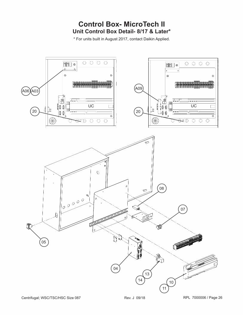
Control Box- MicroTech IIUnit Control Box Detail- 8/17 & Later** For units built in August 2017, contact Daikin Applied.
14
08
13
07
20
05
04
20
A03A06 A09
UC UC
1110
RPL 7000006 / Page 27Centrifugal; WSC/TSC/HSC Size 087 Rev. J 09/18
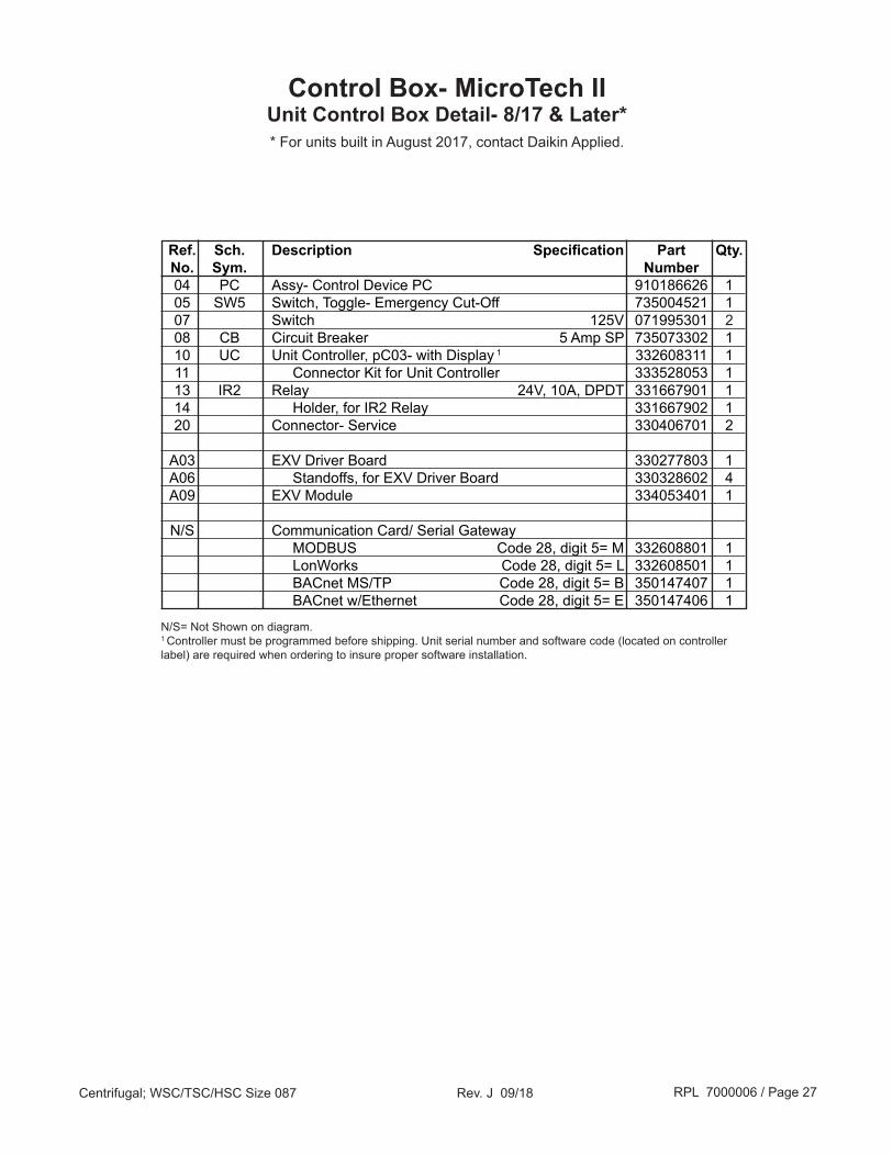
N/S= Not Shown on diagram.1 Controller must be programmed before shipping. Unit serial number and software code (located on controller label) are required when ordering to insure proper software installation.
Ref. Sch. Description Specification Part Qty. No. Sym. Number 04 PC Assy- Control Device PC 910186626 1 05 SW5 Switch, Toggle- Emergency Cut-Off 735004521 1 07 Switch 125V 071995301 2 08 CB Circuit Breaker 5 Amp SP 735073302 1 10 UC Unit Controller, pC03- with Display 1 332608311 1 11 Connector Kit for Unit Controller 333528053 1 13 IR2 Relay 24V, 10A, DPDT 331667901 1 14 Holder, for IR2 Relay 331667902 1 20 Connector- Service 330406701 2 A03 EXV Driver Board 330277803 1 A06 Standoffs, for EXV Driver Board 330328602 4 A09 EXV Module 334053401 1
N/S Communication Card/ Serial Gateway MODBUS Code 28, digit 5= M 332608801 1 LonWorks Code 28, digit 5= L 332608501 1 BACnet MS/TP Code 28, digit 5= B 350147407 1 BACnet w/Ethernet Code 28, digit 5= E 350147406 1
Control Box- MicroTech IIUnit Control Box Detail- 8/17 & Later** For units built in August 2017, contact Daikin Applied.
RPL 7000006 / Page 28Centrifugal; WSC/TSC/HSC Size 087 Rev. J 09/18
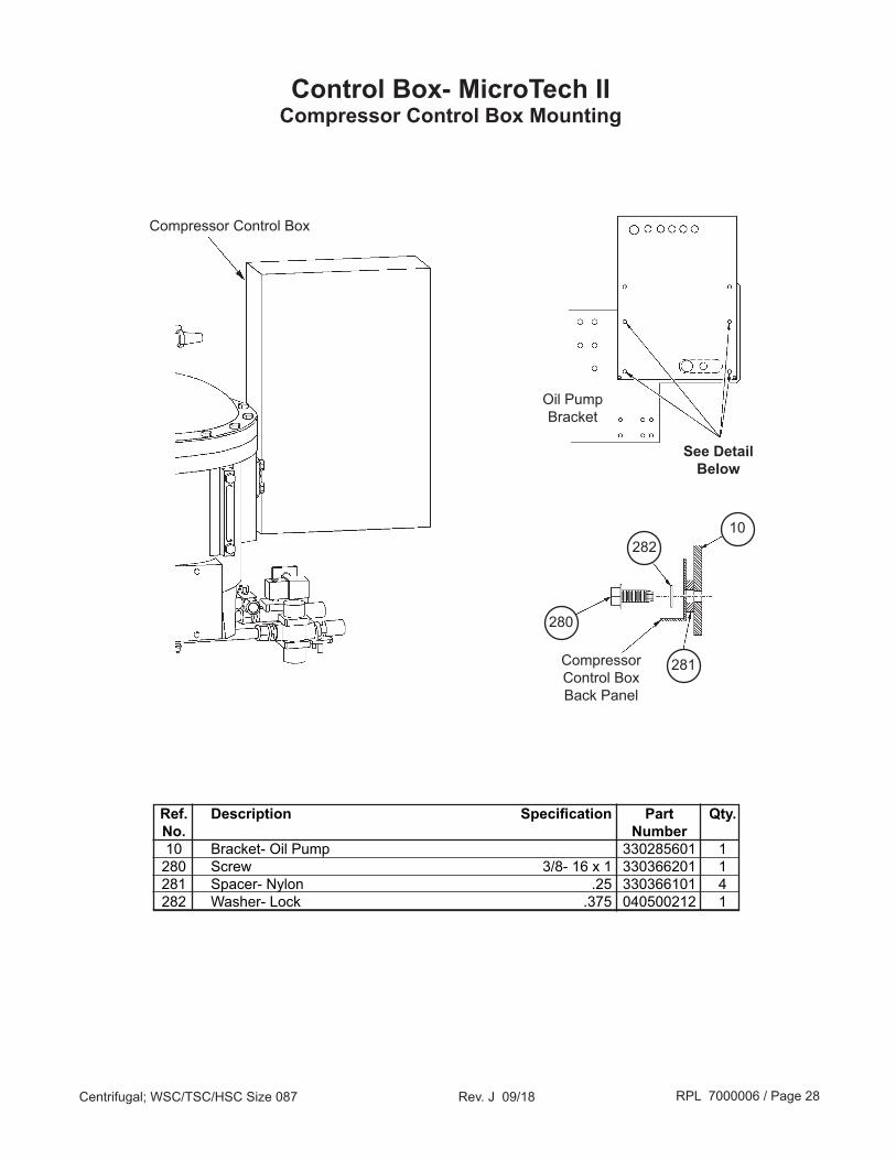
Control Box- MicroTech IICompressor Control Box Mounting
282
280
Compressor Control Box
281
10
Compressor Control BoxBack Panel
See Detail Below
Oil Pump Bracket
Ref. Description Specification Part Qty. No. Number 10 Bracket- Oil Pump 330285601 1 280 Screw 3/8- 16 x 1 330366201 1 281 Spacer- Nylon .25 330366101 4 282 Washer- Lock .375 040500212 1

RPL 7000006 / Page 29Centrifugal; WSC/TSC/HSC Size 087 Rev. J 09/18
Control Box- MicroTech IICompressor Control Box Detail- Until 6/11
10
11 12
4 39
6
2
7
27
18
15
16
17
1
21
22
31
30
528
26
RPL 7000006 / Page 30Centrifugal; WSC/TSC/HSC Size 087 Rev. J 09/18
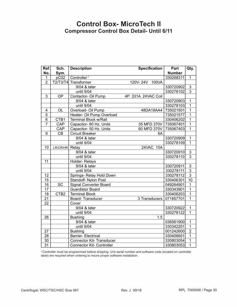
Control Box- MicroTech IICompressor Control Box Detail- Until 6/11
Ref. Sch. Description Specification Part Qty. No. Sym. Number 1 pC02 Controller 1 330268311 1 2 T2/T3/T4 Transformer 120V- 24V 100VA 9/04 & later 330720902 3 until 9/04 330278102 3 3 OP Contactor- Oil Pump 4P 331A 24VAC Coil 9/04 & later 330720903 1 until 9/04 330278103 1 4 OL Overload- Oil Pump 48DA18AA4 735021501 1 5 Heater- Oil Pump Overload 735021577 1 6 CTB1 Terminal Block w/Rail 330406202 1 7 CAP Capacitor- 60 Hz. Units 35 MFD 370V 735067401 1 CAP Capacitor- 50 Hz. Units 60 MFD 370V 735067403 1 9 CB Circuit Breaker 6A 9/04 & later 330720909 1 until 9/04 330278109 1 10 LR/CR/HR Relay 24VAC 10A 9/04 & later 330720910 3 until 9/04 330278110 3 11 Holder- Relays 9/04 & later 330720911 3 until 9/04 330278111 3 12 Springs- Relay Hold Down 330278112 3 15 Standoff- Nylon Post 330406301 10 16 SC Signal Converter Board 049264901 1 17 Guardistor Board 330343901 1 18 CTB2 Terminal Block 330406203 1 21 Board- Transducer 3 Transducers 071857701 1 22 Cover 9/04 & later 330720922 1 until 9/04 330278122 1 26 Bushing 1.5 9/04 & later 036561900 1 until 9/04 330342201 1 27 Bushing 001242600 2 28 Barrier- Electrical 330406601 1 30 Connector Kit- Transducer 330803054 1 31 Connector Kit- Controller 330803053 11 Controller must be programmed before shipping. Unit serial number and software code (located on controller label) are required when ordering to insure proper software installation.
RPL 7000006 / Page 31Centrifugal; WSC/TSC/HSC Size 087 Rev. J 09/18
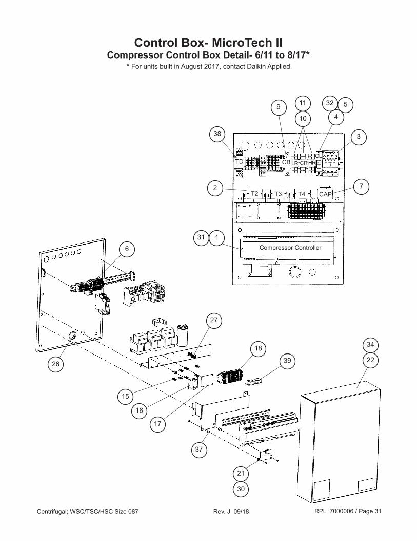
Control Box- MicroTech IICompressor Control Box Detail- 6/11 to 8/17*
2
9
38
30
21
16
37
4
532
3
7
10
15
18
27
39 22
34
17
6
26
CAP
TD CB
T2 T3 T4
CRLR HROL
Compressor Controller131
11
* For units built in August 2017, contact Daikin Applied.

RPL 7000006 / Page 32Centrifugal; WSC/TSC/HSC Size 087 Rev. J 09/18
Control Box- MicroTech IICompressor Control Box Detail- 6/11 to 8/17*
Ref. Sch. Description Specification Part Qty. No. Sym. Number 1 pC03 Controller 1 332608311 1 2 T2/T3/T4 Transformer 120V- 24V 100VA 330720902 3 3 OP Contactor- Oil Pump 4P 331A 24VAC Coil 330720903 1 4 OL Overload- Oil Pump 48DA18AA4 735021501 1 5 Heater- Oil Pump Overload 735021577 1 6 CTB1 Terminal Block w/Rail 330406212 1 7 CAP Capacitor- 60 Hz. Units 35 MFD 370V 735067401 1 CAP Capacitor- 50 Hz. Units 60 MFD 370V 735067403 1 9 CB Circuit Breaker 6A 330720909 1 10 LR/CR/HR Relay 24VAC 10A 330720910 3 11 Holder- Relays 330720911 3 15 Standoff- Nylon Post 330406301 8 16 SC Signal Converter Board 049264901 1 17 Guardistor Board 330343901 1 18 CTB2 Terminal Block 330406233 1 21 Board- Transducer 3 Transducers 071857701 1 22 Cover 330720922 1 26 Bushing 1.5 036561900 1 27 Bushing 001242600 2 30 Connector Kit- Transducer 333528054 1 31 Connector Kit- Controller 333528053 1 32 Barrier- Electrical 330406601 1 34 Gasket- Neoprene .125 x .750 070199209 1.7 ft. 37 Standoff 330328601 2 38 Relay, Time Delay 332843301 1 39 Surge Suppressor 332843401 11 Controller must be programmed before shipping. Unit serial number and software code (located on controller label) are required when ordering to insure proper software installation.
* For units built in August 2017, contact Daikin Applied.

RPL 7000006 / Page 33Centrifugal; WSC/TSC/HSC Size 087 Rev. J 09/18
Control Box- MicroTech IICompressor Control Box Detail- 8/17 & Later*
A09
A10
17
31
28
15
16
2324 2721
07
11
13
06
30
09
20
10
A11
A06 A08A07
* For units built in August 2017, contact Daikin Applied.
RPL 7000006 / Page 34Centrifugal; WSC/TSC/HSC Size 087 Rev. J 09/18
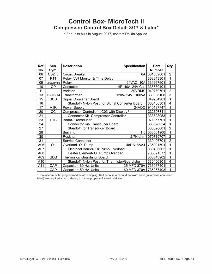
Ref. Sch. Description Specification Part Qty. No. Sym. Number 06 CB2, 3 Circuit Breaker 6A 331669001 2 07 K1T Relay, Volt Monitor & Time Delay 332843301 1 09 LR/CR/HR Relay 24VAC 10A 331667901 3 10 OP Contactor 4P 40A 24V Coil 335659401 1 11 Varistor 30VRMS 049759701 2 13 T2/T3/T4 Transformer 120V- 24V 100VA 330386108 3 15 SCB Signal Converter Board 049264901 1 16 Standoff- Nylon Post, for Signal Converter Board 330406301 4 17 V1R Power Supply 24VDC 910187747 1 20 CC Compressor Controller, pC03 with Display 1 332608311 1 21 Connector Kit- Compressor Controller 333528053 1 23 PTB Board- Transducer 071857701 1 24 Connector Kit- Transducer Board 333528054 1 27 Standoff, for Transducer Board 330328601 2 28 Bushing 1.5 036561900 1 30 Resistor 2.7K ohm 070719707 2 31 Service Connector 330406701 2 A06 OL Overload- Oil Pump 48DA18AA4 735021501 1 A07 Electrical Barrier- Oil Pump Overload 330406602 1 A08 Heater Element- Oil Pump Overload 735021577 1 A09 GDB Thermistor/ Guardistor Board 330343902 1 A10 Standoff- Nylon Post, for Thermistor/Guardistor 330406301 4 A11 CAP Capacitor- 60 Hz. Units 35 MFD 370V 735067401 1 CAP Capacitor- 50 Hz. Units 60 MFD 370V 735067403 11 Controller must be programmed before shipping. Unit serial number and software code (located on controller label) are required when ordering to insure proper software installation.
Control Box- MicroTech IICompressor Control Box Detail- 8/17 & Later*
* For units built in August 2017, contact Daikin Applied.

RPL 7000006 / Page 35Centrifugal; WSC/TSC/HSC Size 087 Rev. J 09/18
Control Box- MicroTech IICables
551 555406
552
411 552995998
17
403
426
402
750
HSC Only559
402A427
866888
552
350
748

RPL 7000006 / Page 36Centrifugal; WSC/TSC/HSC Size 087 Rev. J 09/18
Sensor Application US02 Evaporator Entering Water Temp. US03 Condenser Entering Water Temp. US04 Condenser Leaving Water Temp. US05 Liquid Line Temp. US09 Heat Recovery Entering Water Temp. US10 Heat Recovery Leaving Water Temp.
Unit Control Sensor Application
Sensor Application CS01 Oil Sump Pressure CS02 Oil Feed Gauge Pressure CS03 Evap. Refrigerant Pressure CS04 Oil Sump Temperature CS05 Compressor Suction Temp. CS06 Cond. Refrigerant Pressure CS07 Compressor Discharge Temp. CS08 % Compressor Amps (Starter) CS09 Oil Feed Temperature CS10 Evap. Leaving Water Temp.
Compressor Control Sensor Application
552
55260
350
559
100
558
750
748
557
100
80
552
60
557
552750557
100
557
100
748
555
220
102
552
352
Control Box- MicroTech IISensors
551
748
557
100
558
559
90

RPL 7000006 / Page 37Centrifugal; WSC/TSC/HSC Size 087 Rev. J 09/18
Ref. Sch. Description Specification Part Qty. No. Sym. Number 17 Cable- Operator Interface Panel 330367901 1 Connector Only 330332007 1 60 Conduit Fitting .375" 735048013 7 80 Conduit Fitting .250" 735048015 1 90 Conduit Fitting (for CS05) 6/17 & later 910207144 1 100 Valve Core 026541100 2 102 Sensor Well- Oil Supply Tube 070809042 1 220 Sensor Well until 9/02 070809003 1 Sensor Well 4 9/02 to 3/03 047441511 1 Sensor Well 6 3/05 to 6/17 330198002 1 Sensor Well 6/17 & later 910207143 1 350 CS04 Sensor- Oil Sump 330198001 1 352 Cable- CS04 Sensor 330418501 1 402 Cable, Empty- Comp Heater 1 330006706 1 402A Cable, Empty- Comp Heater 1 330006707 1 403 Cable- Oil Pump Heater 1 330006741 1 406 Cable- Solenoids 330287403 2 411 Cable- Differential Pressure Switches 074608901 ** 426 Cable- Starter 2 Units with Unit Mounted Standard Starter 070829981 1 Units with Free Standing Standard Starter 070829982 1 Units with Unit Mounted VFD 330022982 1 Units with Free Standing VFD 330022981 1 427 Cable- VFD 2 Units with Unit Mounted VFD 330022942 1 Units with Free Standing VFD 330022941 1 551 CS05 Sensor 5 until 3/03 073007302 1 Sensor 5 3/03 to 3/05 330198001 1 Sensor 3/05 to 6/17 330198003 1 Sensor, with Cable 6/17 & later 910207142 1 552 3 Sensor 073007202 *** 555 Cable- CS05 Sensor 3/03 to 6/17 330418501 1 557 Cable- Transducer (see next page) 558 HP1 Switch- High Pressure until 6/03 074796302 1 HP1 Switch- High Pressure 6/03 & later 074796301 1 559 Cable- High Pressure Switch 1 070829997 1 748 CS02/06 Transducer- High (see next page) 750 CS01/03 Transducer- Low (see next page) 866 Cable- 20" Motor 2nd Terminal Box 070829971 1 888 Cable- Guardistor 070829989 1 995 pLAN Cable- pLAN between Unit & Compressor Controller 034248800 **** 998 Cable- Power between Unit & Compressor Controller 330406402 15 ft. N/S Boot- Transducer (see next page)
Control Box- MicroTech IICables and Sensors
N/S= Not Shown on diagram.** There is one cable per DPS (see code 33). Each cable is 16 ft. of the above referenced p/n.*** Quantity is 8 on WSC/TSC units, 10 on HSC units.**** There are two cables. Each made from 15 feet of the above listed p/n.1 Cables contain 90° fitting p/n 000916900 and Anti- Short bushing p/n 047356401.2 See Starter section for all starter- related cables and mounting components.3 CS07, CS08, CS09, CS10, US02, US03, US04, US05 [ US09 & US10 on HSC units only].4 Paste for sensor well is p/n 735026315. This well was used with sensor p/n 073007302 until 3/03.5 The CS05 Sensor change resulted in a relocation of the sensor. After 3/03, the sensor is located in the inlet cone (as shown in the diagram). Before 3/03, the sensor was located in the suction elbow.6 Beginning 3/05 the CS05 sensor was redesigned to use a well. The location remained the same. From 3/03 to 3/05 no well was used.

RPL 7000006 / Page 38Centrifugal; WSC/TSC/HSC Size 087 Rev. J 09/18
Ref. Sch. Description Part Qty. No. Sym. Number Transducers for units built through August 2017 * 557 Cable for Transducers, 10 ft. (includes Boot) 074667501 4 Cable for Transducers, 16 ft. (includes Boot) 074667502 4 Cable for Transducers, 20 ft. (includes Boot) 074667503 4 Cable for Transducers, 25 ft. (includes Boot) 074667504 4
750 CS01 Transducer- Low Pressure, Oil Sump Pressure 071568521 1 CS03 Transducer- Low Pressure, Evap Refrgerant Pressure 071568521 1
748 CS02 Transducer- High Pressure, Oil Feed Gauge Pressure 071568621 1 CS06 Transducer- High Pressure, Cond Refrgerant Pressure 071568621 1
N/S Boot for Transducer Cable (black) 071583301 4
Transducers for units built beginning September 2017 * 557 Cable for Transducers, 10 ft. (includes Boot) 910217971 4 Cable for Transducers, 16 ft. (includes Boot) 910217972 4 Cable for Transducers, 20 ft. (includes Boot) 910217973 4 Cable for Transducers, 25 ft. (includes Boot) 910217974 4
750 CS01 Transducer- Low Pressure, Oil Sump Pressure 333992031 1 CS03 Transducer- Low Pressure, Evap Refrgerant Pressure 333992031 1
748 CS02 Transducer- High Pressure, Oil Feed Gauge Pressure 333992032 1 CS06 Transducer- High Pressure, Cond Refrgerant Pressure 333992032 1
N/S Boot for Transducer Cable (blue) 335657201 4N/S = Not Shown* For units built in August 2017, check the color of the Transducer Cable Boot. If Boot is black, use the parts above for “through August 2017”. If Boot is blue, use the parts above for “beginning September 2017”.
Control Box- MicroTech IICables and Sensors

RPL 7000006 / Page 39Centrifugal; WSC/TSC/HSC Size 087 Rev. J 09/18
Ref. Description Specification Part Qty. No. Number 317 Bracket- Starter Mounting 350257302 4 426 Cable Starter to Compressor Control Box 070829980 1 443 Nut .50- 13 735029505 16 445 Screw .50 x 1.2 735033846 16 447 Washer- Lock .50 Nom. 048164814 16 448 Angle Bracket 330107901 4 450 Washer- Lock .75 Nom. 040500215 32 452 Washer- Plain .50 Nom. 040500311 32 856 Shroud- Terminals 15" Motor 1
26" Evaporator Diameter 074865604 1 30" Evaporator Diameter 074865605 1 36" Evaporator Diameter 074865606 1 Shroud- Terminals 20" Motor 1
26" Evaporator Diameter 074865602 1 30" Evaporator Diameter 074865603 1 36" Evaporator Diameter 074865605 1
StarterUnits with MicroTech 200 Control Box
Control Box- to- Starter Cable, Mounting
447
443
450
426
452
450
450
448
445
447
445452
447
445
Mounting Bracket
317
448448
856
448
317
317317
End View Front View
NOTE: Diagram references units with factory mounted
starters (Code 29-2= 1 or R)
1 15" motors are style numbers 350218851 thru 350218886 or 074745751 thru 074745786; 20" motors are style numbers 330230601 thru 330230663 (0-600V), 073196101 thru 073196163 (0-600V), 073158601 thru 073158696 (601- 4800V) or 073165301 thru 073165321 (6000V & higher). Motor Style numbers are indicated on the Compressor Data Plate.
RPL 7000006 / Page 40Centrifugal; WSC/TSC/HSC Size 087 Rev. J 09/18
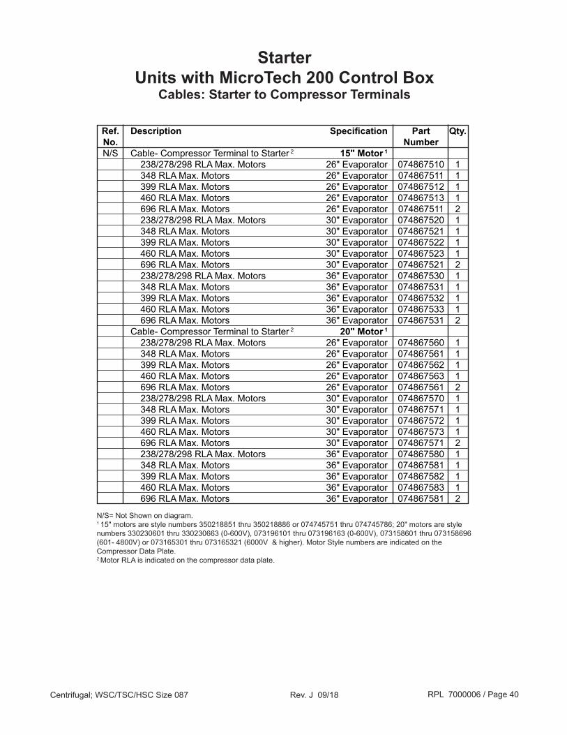
Ref. Description Specification Part Qty. No. Number N/S Cable- Compressor Terminal to Starter 2 15" Motor 1
238/278/298 RLA Max. Motors 26" Evaporator 074867510 1 348 RLA Max. Motors 26" Evaporator 074867511 1 399 RLA Max. Motors 26" Evaporator 074867512 1 460 RLA Max. Motors 26" Evaporator 074867513 1 696 RLA Max. Motors 26" Evaporator 074867511 2 238/278/298 RLA Max. Motors 30" Evaporator 074867520 1 348 RLA Max. Motors 30" Evaporator 074867521 1 399 RLA Max. Motors 30" Evaporator 074867522 1 460 RLA Max. Motors 30" Evaporator 074867523 1 696 RLA Max. Motors 30" Evaporator 074867521 2 238/278/298 RLA Max. Motors 36" Evaporator 074867530 1 348 RLA Max. Motors 36" Evaporator 074867531 1 399 RLA Max. Motors 36" Evaporator 074867532 1 460 RLA Max. Motors 36" Evaporator 074867533 1 696 RLA Max. Motors 36" Evaporator 074867531 2 Cable- Compressor Terminal to Starter 2 20" Motor 1
238/278/298 RLA Max. Motors 26" Evaporator 074867560 1 348 RLA Max. Motors 26" Evaporator 074867561 1 399 RLA Max. Motors 26" Evaporator 074867562 1 460 RLA Max. Motors 26" Evaporator 074867563 1 696 RLA Max. Motors 26" Evaporator 074867561 2 238/278/298 RLA Max. Motors 30" Evaporator 074867570 1 348 RLA Max. Motors 30" Evaporator 074867571 1 399 RLA Max. Motors 30" Evaporator 074867572 1 460 RLA Max. Motors 30" Evaporator 074867573 1 696 RLA Max. Motors 30" Evaporator 074867571 2 238/278/298 RLA Max. Motors 36" Evaporator 074867580 1 348 RLA Max. Motors 36" Evaporator 074867581 1 399 RLA Max. Motors 36" Evaporator 074867582 1 460 RLA Max. Motors 36" Evaporator 074867583 1 696 RLA Max. Motors 36" Evaporator 074867581 2
StarterUnits with MicroTech 200 Control Box
Cables: Starter to Compressor Terminals
N/S= Not Shown on diagram.1 15" motors are style numbers 350218851 thru 350218886 or 074745751 thru 074745786; 20" motors are style numbers 330230601 thru 330230663 (0-600V), 073196101 thru 073196163 (0-600V), 073158601 thru 073158696 (601- 4800V) or 073165301 thru 073165321 (6000V & higher). Motor Style numbers are indicated on the Compressor Data Plate.2 Motor RLA is indicated on the compressor data plate.

RPL 7000006 / Page 41Centrifugal; WSC/TSC/HSC Size 087 Rev. J 09/18
Ref. Description Specification Part Qty. No. Number 20 Angle Bracket 3301079012 4 40 Screw .50 X 1.5 735033847 16 41 Washer- Plain .50 ZPS 040500311 32 42 Washer- Lock .50 ZPS 048164814 16 43 Nut .50- 13 735029505 16 50 Washer- Lock Grounding 040500213 32 51 Washer- Lock .19 ZPS 040500206 4 60 Screw .19 -24 x .50 046093802 4 100 Shroud- Terminals 15" Motor 1 26" Evaporator Diameter 074865604 1 15" Motor 1 30" Evaporator Diameter 074865605 1 15" Motor 1 36" Evaporator Diameter 074865606 1 20" Motor 1 26" Evaporator Diameter 074865602 1 20" Motor 1 30" Evaporator Diameter 074865603 1 20" Motor 1 36" Evaporator Diameter 0748656053 1 317 Bracket- Starter Mounting 350257302 4
Starter - CompactUnits with MicroTech II Control Box
Cables, Mounting
40
100
42
Angle Bracket to Starter 41
43
Shroud MountingTop View
50
50
41
43
40
42
41
317
50
51
100
60
426427
Angle Bracket to Starter Bracket
NOTE: Diagram references units with unit mounted
starters (Code 29-2 = R or M)
VFD Only
1 15" motors are style numbers 350218851 thru 350218886 or 074745751 thru 074745786; 20" motors are style numbers 330230601 thru 330230663 (0-600V), 073196101 thru 073196163 (0-600V), 073158601 thru 073158696 (601- 4800V) or 073165301 thru 073165321 (6000V & higher). Motor Style numbers are indicated on the Compressor Data Plate.2 Units with 20" motors used with VFD use four (4) brackets p/n 330339601. 3 Units with VFD use shroud p/n 074865610.
Starter Panel
20

RPL 7000006 / Page 42Centrifugal; WSC/TSC/HSC Size 087 Rev. J 09/18
Ref. Description Specification Part Qty. No. Number 426 Cable: Starter- to- MicroTech II Control Box Unit Mounted Starter/VFD 2
Standard Starter 4 070829981 1 VFD 5 330022982 1 Free Standing Starter/VFD 3
Standard Starter 4 070829982 1 VFD 5 330022981 1 427 Cable: VFD- to- MicroTech II Control Box Unit Mounted VFD 2, 5 330022942 1 Free Standing VFD 3, 5 330022941 1 N/S Cable: Starter- to- Compressor Terminal 1 15" Motor 238/278/298 RLA Max. Motors 26" Evaporator 074867510 1 348 RLA Max. Motors 26" Evaporator 074867511 1 399 RLA Max. Motors 26" Evaporator 074867512 1 460 RLA Max. Motors 26" Evaporator 074867513 1 696 RLA Max. Motors 26" Evaporator 074867511 2 238/278/298 RLA Max. Motors 30" Evaporator 074867520 1 348 RLA Max. Motors 30" Evaporator 074867521 1 399 RLA Max. Motors 30" Evaporator 074867522 1 460 RLA Max. Motors 30" Evaporator 074867523 1 696 RLA Max. Motors 30" Evaporator 074867521 2 238/278/298 RLA Max. Motors 36" Evaporator 074867520 1 348 RLA Max. Motors 36" Evaporator 074867521 1 399 RLA Max. Motors 36" Evaporator 074867522 1 460 RLA Max. Motors 36" Evaporator 074867523 1 696 RLA Max. Motors 36" Evaporator 074867521 2 Cable- Starter to Compressor Terminal 1 20" Motor 238/278/298 RLA Max. Motors 26" Evaporator 074867560 1 348 RLA Max. Motors 26" Evaporator 074867561 1 399 RLA Max. Motors 26" Evaporator 074867562 1 460 RLA Max. Motors 26" Evaporator 074867563 1 696 RLA Max. Motors 26" Evaporator 074867561 2 238/278/298 RLA Max. Motors 30" Evaporator 074867570 1 348 RLA Max. Motors 30" Evaporator 074867571 1 399 RLA Max. Motors 30" Evaporator 074867572 1 460 RLA Max. Motors 30" Evaporator 074867573 1 696 RLA Max. Motors 30" Evaporator 074867571 2 238/278/298 RLA Max. Motors 36" Evaporator 074867580 1 348 RLA Max. Motors 36" Evaporator 074867581 1 399 RLA Max. Motors 36" Evaporator 074867582 1 460 RLA Max. Motors 36" Evaporator 074867583 1 696 RLA Max. Motors 36" Evaporator 074867581 2
Starter - CompactUnits with MicroTech II Control Box
Cables
N/S= Not Shown on diagram.1 Motor RLA is indicated on the compressor data plate.2 Code 29-2= 1, R, M.3 Code 29-2= 2, 5, 7, 9, L.4 Standard starter are any of the following: Wye-Delta (C29-1= 2); Across-the-Line (C29-1= 3); Auto Transformer (C29-1= 4); Primary Reactor (C29-1= 5); Solid State (C29-1= 6).5 Variable Frequency Drive (C29-1= V). VFD (water cooled) also requires hose fittings (4 each) p/n 330465001 & 330465101, and 18 foot of low pressure hose p/n 330465202.

RPL 7000006 / Page 43Centrifugal; WSC/TSC/HSC Size 087 Rev. J 09/18
Starter - Mini Cabinet (Code 29-1=G)Units with MicroTech II Control Box
Cables, Mounting
Ref. Description Specification Part Qty. No. Number 20 Angle Bracket 330107901 4 40 Screw .50 X 1.5 735033847 8 41 Washer- Plain .50 ZPS 040500311 16 42 Washer- Lock .50 ZPS 048164814 8 43 Nut .50- 13 735029505 8 46 Screw .37 x 1.2 735033233 8 47 Washer- Plain .38 ZPS 040500316 8 48 Washer- Lock .38 ZPS 048164812 8 49 Nut .38- 16 040499906 8 50 Washer- Lock Grounding 040500213 16 51 Washer- Lock .19 ZPS 040500206 4 52 Washer- Lock 040500212 16 60 Screw .19 -24 x .50 046093802 4 317 Bracket- Starter Mounting 350257302 4 426 Cable- Starter see Control Box- MTII- Cables & Sensors 427 Cable- VFD 1 see Control Box- MTII- Cables & Sensors
42
60
20
Angle Bracket to Starter
43
50
47
50
46
48
52
49
2041
317
41
Starter
426427
Angle Bracket to Starter Bracket
VFD Only
1 VFD (water cooled) also requires hose fittings (4 each) p/n 330465001 & 330465101, and 18 foot of low pressure hose p/n 330465202.
51
40
Starter
NOTE: This diagram applies to unit mounted mini cabinet starters only
(Code 29-2= G)

RPL 7000006 / Page 44Centrifugal; WSC/TSC/HSC Size 087 Rev. J 09/18
Differential Pressure SwitchFactory Mounted & Wired (Code 33= B, C or E)
Switches, Wells, Power Cables, Fittings
667 656
411
651
Wiring- MicroTech 200 Control
Wiring- MicroTech II Control
CHW1- NO
CW1- NO
CW1 & CHW1- C
EF- NO EF & CF- C
NOTES:The water pressure differential switch is an optional component. It is factory installed and wired when code 33= E (evaporator only), C (condenser only) or B (both condenser and evaporator). The switches used for either the MicroTech 200 or the MicroTech II control types are the same as are the wells. However the schematic designations are different. MicroTech 200 units designate the Evaporator & Condenser switches as CHW1 & CH1, while the MicroTech II units designate the same switches as EF1 & CF1. The only component part number difference of note are the power cables.
412
Ref. Description Part Qty.* No. Number 411 Cable- Evaporator DPS MicroTech 200 Control 071543662 1 MicroTech II Control (until 5/04) 074608901 16 ft. MicroTech II Control (5/04 & later) 330571402 1 412 Cable- Condenser DPS MicroTech 200 Control 071543661 1 MicroTech II Control (until 5/04) 074608901 16 ft. MicroTech II Control (5/04 & later) 330571402 1 651 Differential Pressure Switch (until 5/04) 070180519 2 Differential Pressure Switch (5/04 & later) 330571401 1 656 Flare Nut (2 per tube) (until 5/04) 000028600 8 667 Sensor Well (until 5/04) 072867501 4 667A Elbow (until 5/04) 001276600 4 667B Tube (until 5/04) 070221602 4 667C Nozzle (until 5/04) 072867511 4 667 Sensor Well (5/04 & later) 047441511 4 N/S Fitting (5/04 & later) 735048013 4
651
*Quantities are based on the presence of both DPS (Code 33= B). If code 33= E or C part numbers 651 & 656 quantities are 1 & 4 respectively, and only one cable (411 if C33= E or 412 if C33= C) is used. If only one DPS is used, the well (ref. # 667) has a quanity of 2- 072867501 (used on the vessel with the DPS) and 2- 047441511 (used on the vessel without the DPS).
667A
Well Detail (ref. 667)Until 5/04
Differential Pressure Switch- None (Code 33= Y)Wells
Description Part Qty. Number Sensor Well (Evap & Cond in/out nozzles) 047441511 4
N/S= Not shown on diagram.
667B
667C
CF- NO

RPL 7000006 / Page 45Centrifugal; WSC/TSC/HSC Size 087 Rev. J 09/18
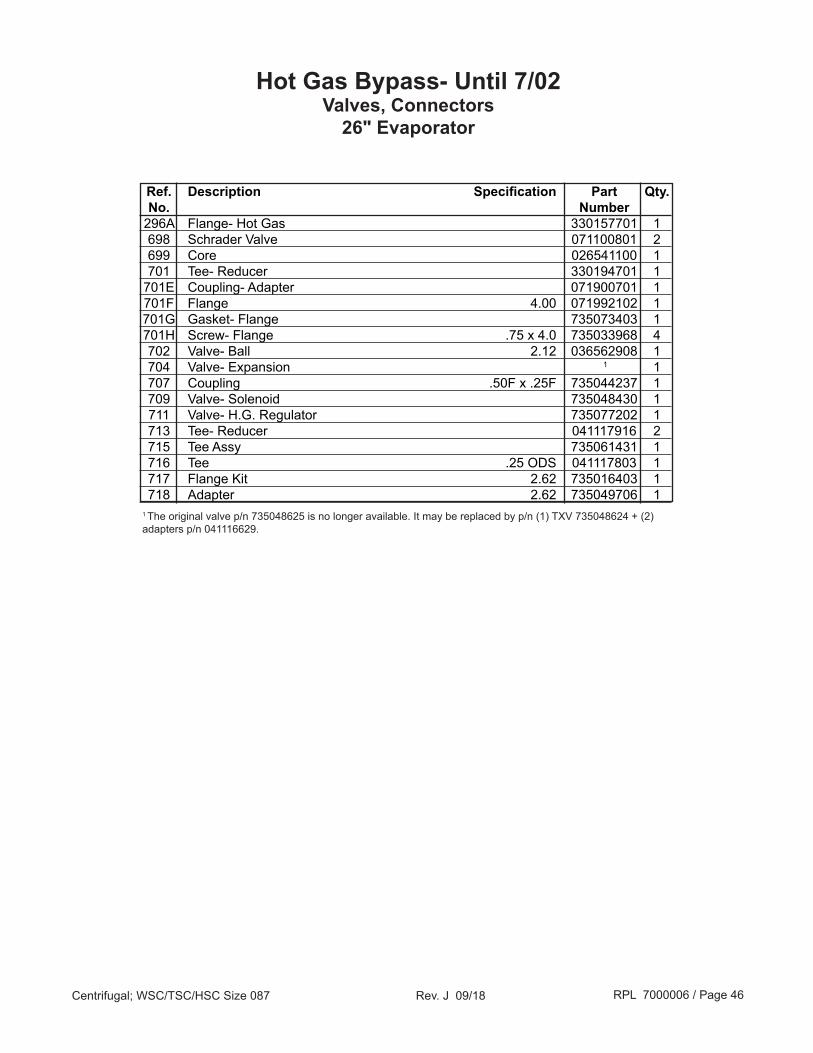
Hot Gas Bypass- Until 7/02Valves, Connectors
The Hot Gas Bypass was redesigned in mid 2002. The placement of the ball valve and HGBP regulator were changed and consequently the tubing configuration is different.
30" & 36" Evaporator
26" Evaporator
707
717 718
TXV
716715
704
713
711 709
699
698
702
701
296A
701E701F701G701H
296A
702
OR
TXV
RPL 7000006 / Page 46Centrifugal; WSC/TSC/HSC Size 087 Rev. J 09/18
Hot Gas Bypass- Until 7/02Valves, Connectors
26" Evaporator
Ref. Description Specification Part Qty. No. Number 296A Flange- Hot Gas 330157701 1 698 Schrader Valve 071100801 2 699 Core 026541100 1 701 Tee- Reducer 330194701 1 701E Coupling- Adapter 071900701 1 701F Flange 4.00 071992102 1 701G Gasket- Flange 735073403 1 701H Screw- Flange .75 x 4.0 735033968 4 702 Valve- Ball 2.12 036562908 1 704 Valve- Expansion 1 1 707 Coupling .50F x .25F 735044237 1 709 Valve- Solenoid 735048430 1 711 Valve- H.G. Regulator 735077202 1 713 Tee- Reducer 041117916 2 715 Tee Assy 735061431 1 716 Tee .25 ODS 041117803 1 717 Flange Kit 2.62 735016403 1 718 Adapter 2.62 735049706 11 The original valve p/n 735048625 is no longer available. It may be replaced by p/n (1) TXV 735048624 + (2) adapters p/n 041116629.

RPL 7000006 / Page 47Centrifugal; WSC/TSC/HSC Size 087 Rev. J 09/18
Hot Gas Bypass- Until 7/02Valves, Connectors
30" & 36" Evaporator
Ref. Description Specification Part Qty. No. Number 296A Flange- Hot Gas 350302351 1 698 Schrader Valve 071100801 2 699 Core 026541100 1 702 Valve- Ball 2.625 073055601 1 704 Valve- Expansion 735048624 1 707 Coupling .50F x .25F 735044237 1 709 Valve- Solenoid 735048430 1 711 Valve- H.G. Regulator 735077202 1 713 Tee- Reducer 041117916 2 715 Tee Assy 735061431 1 716 Tee .25 ODS 041117803 1 717 Flange Kit 2.62 735016403 1 718 Adapter 2.62 735049706 1

RPL 7000006 / Page 48Centrifugal; WSC/TSC/HSC Size 087 Rev. J 09/18
62
140
80
WSC/TSC/HSC Hot Gas Bypass- 7/02 to 12/04Valves, Connectors
63
180
91
200201202
210
211
260
240
310 350 351
310350
330
361360
Until 2/04
2/04 & Later
62
140
8063
180
91
200201202
210
211
260
240310 350 351
310350
361360
180
180

RPL 7000006 / Page 49Centrifugal; WSC/TSC/HSC Size 087 Rev. J 09/18
Ref. Description Specification Part Qty. No. Number 62 Flange Kit- 26" & 30" Condenser Only 10/03 & later 735016402 1 63 Adapter- 26" & 30" Condenser Only 10/03 & later 735049705 1 80 Expansion Valve* until 10/03 735048625 1 1
Expansion Valve* 10/03 & later 735048624 1 1
91 Insulation 047662050 *** 140 Valve- Ball* 330286008 1 180 Reducer until 10/03 041116629 1 Reducer 10/03 & later 041116629 3 1
200 Adapter* 735049706 1 201 Flange Kit* 735016403 1 202 Gasket* 070199113 2 210 Tee 041117803 1 211 Tee 735061431 1 240 Valve- Hot Gas Regulator* 735077202 1 260 Valve- Solenoid* 735048468 1 310 Tee 041117916 2 350 Schrader Valve* 071100801 1 351 Core- Valve* 026541100 1 360 Coupling* 735044237 1 361 O'Ring* 735073639 1
*HSC NOTE: These components apply to HSC units.** This date is approximate. For units built between 11/04 and 4/05 visual verification is required. If not sure, contact Daikin Applied with unit model and serial number to verify.***Quantity in square feet, as needed.1 All unit stacks built prior to 10/03 used p/n 735048625. This expansion valve was discontinued and replaced by valve p/n 735048624 and two (2) reducers p/n 041116629 (ref. #180).
WSC/TSC/HSC* Hot Gas Bypass- 7/02 to 12/04**Valves, Connectors

RPL 7000006 / Page 50Centrifugal; WSC/TSC/HSC Size 087 Rev. J 09/18
20
5
30
WSC/TSC Hot Gas Bypass- 1/05 to Present*Electronic Expansion Valve, Ball Valve, Connectors
5
13
2
53 52 51
5
Ref. Description Specification Part Qty. No. Number 1 Gasket- Flange 070199113 1 2 Adapter- Flange 735049706 1 3 Flange Kit 735016403 1 5 Reducer 041116629 3 20 Valve- Ball 330286008 1 30 Valve- Electronic Expansion 330386205 1 51 Flange Kit 735016402 1 52 Adapter- Flange 735049705 1 53 Gasket- Flange 070199112 1
* This date is approximate. For units built between 11/04 and 4/05 visual verification is required. If not sure, contact Daikin Applied with unit model & serial number to verify.

RPL 7000006 / Page 51Centrifugal; WSC/TSC/HSC Size 087 Rev. J 09/18
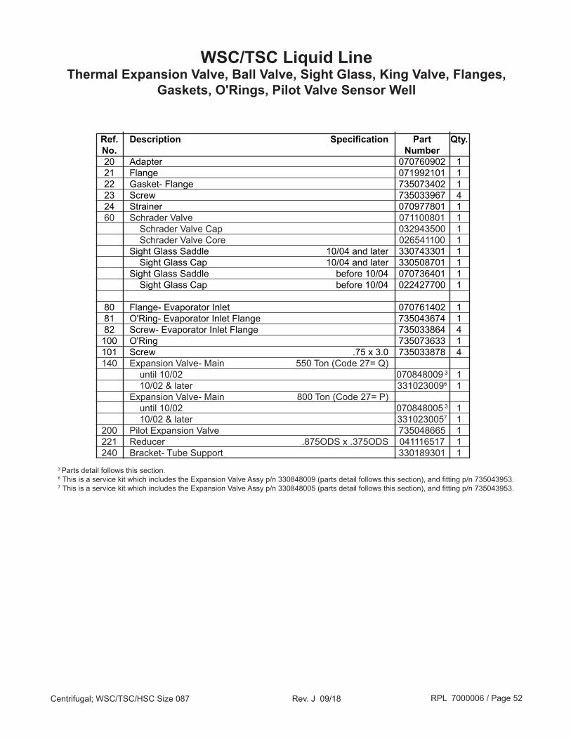
WSC/TSC Liquid LineThermal Expansion Valve, Ball Valve, Sight Glass, King Valve,
Flanges, Gaskets, O'Rings, Pilot Valve Sensor Well
251
253
338
Condenser
End ViewKing Valve to
Condenser Detail
330
252
331
308
312313314
Pressure Connector (ref. # 304) Detail
Pilot Valve Bulb Detail
304
300
26020
21
262254
22
23
24
240241
242
60
80
8281100
140101
307 306
200
221
300A300B
RPL 7000006 / Page 52Centrifugal; WSC/TSC/HSC Size 087 Rev. J 09/18
Ref. Description Specification Part Qty. No. Number 20 Adapter 070760902 1 21 Flange 071992101 1 22 Gasket- Flange 735073402 1 23 Screw 735033967 4 24 Strainer 070977801 1 60 Schrader Valve 071100801 1 Schrader Valve Cap 032943500 1 Schrader Valve Core 026541100 1 Sight Glass Saddle 10/04 and later 330743301 1 Sight Glass Cap 10/04 and later 330508701 1 Sight Glass Saddle before 10/04 070736401 1 Sight Glass Cap before 10/04 022427700 1
80 Flange- Evaporator Inlet 070761402 1 81 O'Ring- Evaporator Inlet Flange 735043674 1 82 Screw- Evaporator Inlet Flange 735033864 4 100 O'Ring 735073633 1 101 Screw .75 x 3.0 735033878 4 140 Expansion Valve- Main 550 Ton (Code 27= Q) until 10/02 070848009 3 1 10/02 & later 3310230096 1 Expansion Valve- Main 800 Ton (Code 27= P) until 10/02 070848005 3 1 10/02 & later 3310230057 1 200 Pilot Expansion Valve 735048665 1 221 Reducer .875ODS x .375ODS 041116517 1 240 Bracket- Tube Support 330189301 1
3 Parts detail follows this section.6 This is a service kit which includes the Expansion Valve Assy p/n 330848009 (parts detail follows this section), and fitting p/n 735043953.7 This is a service kit which includes the Expansion Valve Assy p/n 330848005 (parts detail follows this section), and fitting p/n 735043953.
WSC/TSC Liquid LineThermal Expansion Valve, Ball Valve, Sight Glass, King Valve, Flanges,
Gaskets, O'Rings, Pilot Valve Sensor Well

RPL 7000006 / Page 53Centrifugal; WSC/TSC/HSC Size 087 Rev. J 09/18
Ref. Description Specification Part Qty. No. Number 241 Clamp- Tube 040971308 1 242 Screw .19-24 x .50 046093802 1 251 Valve- Main Liquid (King) 3.00" 735039807 1 252 Screw- King Valve .62 x 5.0 735033957 4 253 Gasket- King Valve 070199104 1 254 Cap- King Valve 071556902 1 260 Strainer 735030501 1 262 Ball Valve 330286004 1 300 Tee Assembly 735061434 1 300A Valve, Ball- Tee 0.25 330286099 1 300B Valve, Ball- Tee 0.50 330286002 1 304 Pressure Connector 070811202 1 306 Fitting- Sleeve Orifice 070789328 1 307 Fitting- Nut Orifice 070789327 1 308 Flare Nut 2 000028600 1 312 Valve Core 2 026541100 1 313 Schrader Valve 2 071100801 1 314 Schrader Valve Cap 2 032943500 1 330 Valve- Shutoff .375" Flare 735039907 1 Cap for Shutoff Valve 071556909 1 331 Flare Cap 000540900 1 338 Sensor Well- Pilot Valve located at top of evaporator 735946401 1
WSC/TSC Liquid LineThermal Expansion Valve, Ball Valve, Sight Glass, King Valve,
Flanges, Gaskets, O'Rings, Pilot Valve Sensor Well
2 Part of pressure connector assembly (ref. #304).
RPL 7000006 / Page 54Centrifugal; WSC/TSC/HSC Size 087 Rev. J 09/18
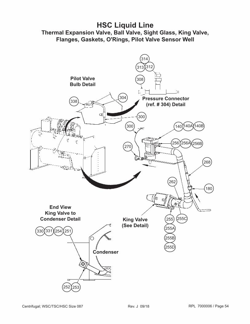
HSC Liquid LineThermal Expansion Valve, Ball Valve, Sight Glass, King Valve,
Flanges, Gaskets, O'Rings, Pilot Valve Sensor Well
251
253
338
Condenser
End ViewKing Valve to
Condenser Detail
330
252
331
308
312313
314
Pressure Connector (ref. # 304) Detail
Pilot Valve Bulb Detail
304
268
254
140 140B140A
256B256 256A
180262
255
300
270
255A
255B
255D
300
King Valve(See Detail)
255C

RPL 7000006 / Page 55Centrifugal; WSC/TSC/HSC Size 087 Rev. J 09/18
HSC Liquid LineThermal Expansion Valve, Ball Valve, Sight Glass, King Valve,
Flanges, Gaskets, O'Rings, Pilot Valve Sensor Well
Ref. Description Specification Part Qty. No. Number 140 Expansion Valve- Main 550 Ton (Code 27= Q) 1 until 10/02 0708480091 1 10/02 & later 3310230094 1 Expansion Valve- Main 800 Ton (Code 27= P) 1 until 10/02 0708480051 1 10/02 & later 3310230055 1 140A O'Ring 735073623 1 140B Screw 735033878 4 180 Ball Valve 330286004 1 251 Valve- Main Liquid (King) 735039809 1 252 Screw- King Valve 735033973 4 253 Gasket- King Valve 070199106 1 254 Cap- King Valve 071556903 1 255 Coupling 071901601 1 255A Flange 071992102 1 255B Gasket 735073403 1 255C Strainer Assy 070977802 1 255D Screw 735033967 4 256 Flange 070761402 1 256A Screw 735033864 4 256B O'Ring 735043674 1 262 Schrader Valve 071100801 1 Schrader Valve Cap 032943500 1 Schrader Valve Core 026541100 1 Sight Glass Saddle 10/04 and later 330743301 1 Sight Glass Cap 10/04 and later 330508701 1 Sight Glass Saddle before 10/04 070736401 1 Sight Glass Cap before 10/04 022427700 1 268 Strainer 735030501 1 270 Pilot Expansion Valve 735048665 1 300 Tee Assy 735061444 1 304 Pressure Connector 070811202 1 N/S Fitting- Sleeve Orifice 070789328 1 N/S Fitting- Nut Orifice 070789327 1 308 Flare Nut 3 000028600 1 312 Valve Core 3 026541100 1 313 Schrader Valve 3 071100801 1 314 Schrader Valve Cap 3 032943500 1 330 Valve- Shutoff .375" Flare 735039929 1 Cap for Shutoff Valve 071556909 1 331 Flare Cap 073243901 1 338 Sensor Well- Pilot Valve located at top of evaporator 735946401 1
HSC NOTE: Contact Daikin Applied for part numbers of tubing not referenced in drawing.1 Parts detail on following page.3 Part of pressure connector assembly (ref. #304).4This is a service kit which includes the Expansion Valve Assy p/n 330848009 (parts detail follows this section), and fitting p/n 735043953.5This is a service kit which includes the Expansion Valve Assy p/n 330848005 (parts detail follows this section), and fitting p/n 735043953.
RPL 7000006 / Page 56Centrifugal; WSC/TSC/HSC Size 087 Rev. J 09/18
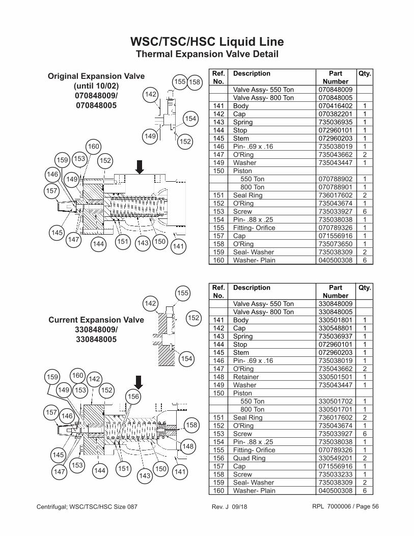
WSC/TSC/HSC Liquid LineThermal Expansion Valve Detail
153
160
152
149146
157
145147 144 151 143 150
141
155 158
142
149
154
152
148
158
156152
142153
145
147 144143
150 141
160
153 151
142
154
155
152
149
146157
Ref. Description Part Qty. No. Number Valve Assy- 550 Ton 070848009 Valve Assy- 800 Ton 070848005 141 Body 070416402 1 142 Cap 070382201 1 143 Spring 735036935 1 144 Stop 072960101 1 145 Stem 072960203 1 146 Pin- .69 x .16 735038019 1 147 O'Ring 735043662 2 149 Washer 735043447 1 150 Piston 550 Ton 070788902 1 800 Ton 070788901 1 151 Seal Ring 736017602 2 152 O'Ring 735043674 1 153 Screw 735033927 6 154 Pin- .88 x .25 735038038 1 155 Fitting- Orifice 070789326 1 157 Cap 071556916 1 158 O'Ring 735073650 1 159 Seal- Washer 735038309 2 160 Washer- Plain 040500308 6
Ref. Description Part Qty. No. Number Valve Assy- 550 Ton 330848009 Valve Assy- 800 Ton 330848005 141 Body 330501801 1 142 Cap 330548801 1 143 Spring 735036937 1 144 Stop 072960101 1 145 Stem 072960203 1 146 Pin- .69 x .16 735038019 1 147 O'Ring 735043662 2 148 Retainer 330501501 1 149 Washer 735043447 1 150 Piston 550 Ton 330501702 1 800 Ton 330501701 1 151 Seal Ring 736017602 2 152 O'Ring 735043674 1 153 Screw 735033927 6 154 Pin- .88 x .25 735038038 1 155 Fitting- Orifice 070789326 1 156 Quad Ring 330549201 2 157 Cap 071556916 1 158 Screw 735033233 1 159 Seal- Washer 735038309 2 160 Washer- Plain 040500308 6
Original Expansion Valve(until 10/02)070848009/070848005
Current Expansion Valve330848009/330848005
159
159
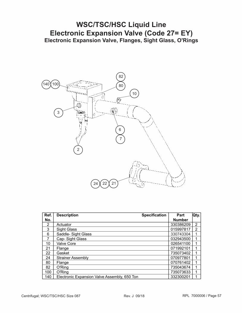
RPL 7000006 / Page 57Centrifugal; WSC/TSC/HSC Size 087 Rev. J 09/18
WSC/TSC/HSC Liquid LineElectronic Expansion Valve (Code 27= EY)
Electronic Expansion Valve, Flanges, Sight Glass, O'Rings
Ref. Description Specification Part Qty. No. Number 2 Actuator 330386209 2 3 Sight Glass 015997817 2 6 Saddle- Sight Glass 330743304 1 7 Cap- Sight Glass 032943500 1 10 Valve Core 026541100 1 21 Flange 071992101 1 22 Gasket 735073402 1 24 Strainer Assembly 070977801 1 80 Flange 070761402 1 82 O'Ring 735043674 1 100 O'Ring 735073633 1 140 Electronic Expansion Valve Assembly, 650 Ton 332300201 1
140
21
7
2224
6
80100
82
10
3
2

RPL 7000006 / Page 58Centrifugal; WSC/TSC/HSC Size 087 Rev. J 09/18
Condenser & Evaporator ValvesRelief Valves, Shutoff Valves
331
Ref. Description Specification Part Qty. No. Number 21 Valve- Shut Off 1 (used on 18",20",26" Condensers) 1" NPT 735039977 1 21 Valve- Shut Off 1 (used on 22" Condensers) 1" NPT 735039964 1 22 Valve- Relief 1 200 PSI 735045817 3 330 Valve- Shutoff .625" 735039929 3 Cap for Shutoff Valve 071556909 3 331 Flare Cap .625" 073243901 3
330
21
331 330
331 330
22
22
1 Some HSC units have a second set of condenser relief valve parts. On such units there is an additional (1) shutoff valve (ref. # 21) and (2) relief valve (ref. # 22).

RPL 7000006 / Page 59Centrifugal; WSC/TSC/HSC Size 087 Rev. J 09/18
Unit Insulation
Description Specification Part Quantity Number Insulation 0.75 thickness 047662050 Square feet - As needed
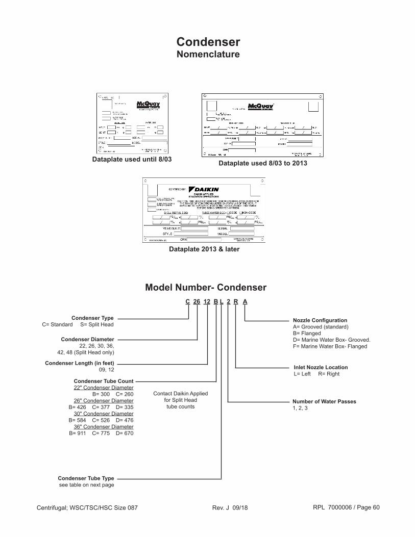
RPL 7000006 / Page 60Centrifugal; WSC/TSC/HSC Size 087 Rev. J 09/18
CondenserNomenclature
Condenser Diameter22, 26, 30, 36,
42, 48 (Split Head only)
Model Number- CondenserC 26 12 B L 2 R A
Number of Water Passes1, 2, 3
Condenser Length (in feet)09, 12
Condenser TypeC= Standard S= Split Head
Condenser Tube Count22" Condenser Diameter
B= 300 C= 26026" Condenser Diameter
B= 426 C= 377 D= 33530" Condenser Diameter
B= 584 C= 526 D= 47636" Condenser Diameter
B= 911 C= 775 D= 670
Inlet Nozzle LocationL= Left R= Right
Nozzle ConfigurationA= Grooved (standard)B= FlangedD= Marine Water Box- Grooved.F= Marine Water Box- Flanged
Condenser Tube Typesee table on next page
Dataplate used until 8/03 Dataplate used 8/03 to 2013
Contact Daikin Applied for Split Head tube counts
Dataplate 2013 & later

RPL 7000006 / Page 61Centrifugal; WSC/TSC/HSC Size 087 Rev. J 09/18
CondenserHeads
To properly identify Condenser Heads, please contact Daikin Applied with the Unit SO and/or GO Number; and the Unit Serial Number. If available, also include the Condenser Style Number and Serial Number.
HSC- Split Head
Return
Connection
1- Pass
2- Pass
3- Pass
Head Types
Standard Grooved Standard Flanged Water Box Grooved Water Box Flanged Connection Return Connection Return Connection Return Connection Return

RPL 7000006 / Page 62Centrifugal; WSC/TSC/HSC Size 087 Rev. J 09/18
CondenserSight Glass, Flange, Tubes, Head Gaskets
Shut Off Valve**
King Valve*116 100
110King Valve*
Shut Off Valve*
352355
Front View End View
*See Liquid Line Section** See Evap & Cond. Relief Valve Section
ConnectionHead
Return Head
Ref. Description Specification Part Qty. No. Number 100 Tubes- See tube table below 110 Sight Glass 350229501 1 116 Flange- Liquid Line WSC/TSC 350256901 1 Flange- Liquid Line HSC 070261502 1
Tube Code Wall 9 3/4" 1" (6th digit) Thickness foot 12 foot 12 foot L .025 330441407 330441408 330441428 N .028 330441424 330441425 330441442 P .035 073238578 073238577 330441443
Tube Table

RPL 7000006 / Page 63Centrifugal; WSC/TSC/HSC Size 087 Rev. J 09/18
CondenserGaskets- Dish Head
Split-Head Condenser Gaskets (Code 16= Sxxxx)Contact Daikin Applied with the Unit SO and/or GO Number; and the Unit Serial Number.
If available, also include the Condenser Style Number and Serial Number.
Ref. # Description Part Number Qty.
1 Pass, 150 PSI, Dish Heads, non-ASME 352/355 Gasket, Head 070304645 2
2 Pass, 150 PSI, Dish Heads, non-ASME 352 Gasket Kit, Connection Head 333849805 1 355 Gasket, Return Head 070304645 1
3 Pass, 150 PSI, Dish Heads, non-ASME 352/355 Gasket Kit, Head 333849805 2
Ref. # Description Part Number Qty.
1 Pass, 150 PSI, Dish Heads, non-ASME 352/355 Gasket, Head 070304646 2
2 Pass, 150 PSI, Dish Heads, non-ASME 352 Gasket Kit, Connection Head 333849806 1 355 Gasket, Return Head 070304646 1
3 Pass, 150 PSI, Dish Heads, non-ASME 352/355 Gasket Kit, Head 333849806 2
22 Inch Condenser (Code 16= C22xx)
24 or 26 Inch Condenser (Code 16= C24xx or C26xx)

RPL 7000006 / Page 64Centrifugal; WSC/TSC/HSC Size 087 Rev. J 09/18
CondenserGaskets- Dish Head
Split-Head Condenser Gaskets (Code 16= Sxxxx)Contact Daikin Applied with the Unit SO and/or GO Number; and the Unit Serial Number.
If available, also include the Condenser Style Number and Serial Number.
Ref. # Description Part Number Qty.
1 Pass, 150 PSI, Dish Heads, non-ASME 352/355 Gasket, Head 070304621 2
2 Pass, 150 PSI, Dish Heads, non-ASME 352 Gasket Kit, Connection Head 333849807 1 355 Gasket, Return Head 070304621 1
3 Pass, 150 PSI, Dish Heads, non-ASME 352/355 Gasket Kit, Head 333849807 2
30 Inch Condenser (Code 16= C30xx)
Ref. # Description Part Number Qty.
1 Pass, 150 PSI, Dish Heads, non-ASME 352/355 Gasket, Head 070304622 2
2 Pass, 150 PSI, Dish Heads, non-ASME 352 Gasket Kit, Connection Head 333849808 1 355 Gasket, Return Head 070304622 1
3 Pass, 150 PSI, Dish Heads, non-ASME 352/355 Gasket Kit, Head 333849808 2
36 Inch Condenser (Code 16= C36xx)

RPL 7000006 / Page 65Centrifugal; WSC/TSC/HSC Size 087 Rev. J 09/18
CondenserGaskets- Water Box Heads
Split-Head Condenser Gaskets (Code 16= Sxxxx)Contact Daikin Applied with the Unit SO and/or GO Number; and the Unit Serial Number. If available, also include the Condenser Style Number and Serial Number.
Ref. # Description Part Number Qty.
1 Pass, 150 PSI, Water Box Heads, non-ASME 352/366 Gasket, Head 070304645 4
2 Pass, 150 PSI, Water Box Heads, non-ASME 352 Gasket Kit, Water Box to Shell 333849905 1 355 Gasket, Return Head 070304645 1 366 Gasket Kit, Water Box Cover 333850005 1
3 Pass, 150 PSI, Water Box Heads, non-ASME 352 Gasket Kit, Water Box to Shell 333850005 2 366 Gasket Kit, Water Box Cover 333850005 2
22 Inch Condenser (Code 16= C22xx)
Ref. # Description Part Number Qty.
1 Pass, 150 PSI, Water Box Heads, non-ASME 352/366 Gasket, Head 070304646 4
2 Pass, 150 PSI, Water Box Heads, non-ASME 352 Gasket Kit, Water Box to Shell 333849906 1 355 Gasket, Return Head 070304646 1 366 Gasket Kit, Water Box Cover 333850006 1
3 Pass, 150 PSI, Water Box Heads, non-ASME 352 Gasket Kit, Water Box to Shell 333849906 2 366 Gasket Kit, Water Box Cover 333850006 2
24 or 26 Inch Condenser (Code 16= C24xx or 26xx)

RPL 7000006 / Page 66Centrifugal; WSC/TSC/HSC Size 087 Rev. J 09/18
CondenserGaskets- Water Box Heads
Split-Head Condenser Gaskets (Code 16= Sxxxx)Contact Daikin Applied with the Unit SO and/or GO Number; and the Unit Serial Number. If available, also include the Condenser Style Number and Serial Number.
Ref. # Description Part Number Qty.
1 Pass, 150 PSI, Water Box Heads, non-ASME 352/366 Gasket, Head 070304621 4
2 Pass, 150 PSI, Water Box Heads, non-ASME 352 Gasket Kit, Water Box to Shell 333849907 1 355 Gasket, Return Head 070304621 1 366 Gasket Kit, Water Box Cover 333850007 1
3 Pass, 150 PSI, Water Box Heads, non-ASME 352 Gasket Kit, Water Box to Shell 333849907 2 366 Gasket Kit, Water Box Cover 333850007 2
30 Inch Condenser (Code 16= C30xx)
Ref. # Description Part Number Qty.
1 Pass, 150 PSI, Water Box Heads, non-ASME 352/366 Gasket, Head 070304622 4
2 Pass, 150 PSI, Water Box Heads, non-ASME 352 Gasket Kit, Water Box to Shell 333849908 1 355 Gasket, Return Head 070304622 1 366 Gasket Kit, Water Box Cover 333850008 1
3 Pass, 150 PSI, Water Box Heads, non-ASME 352 Gasket Kit, Water Box to Shell 333850008 2 366 Gasket Kit, Water Box Cover 333850008 2
36 Inch Condenser (Code 16= C36xx)

RPL 7000006 / Page 67Centrifugal; WSC/TSC/HSC Size 087 Rev. J 09/18
EvaporatorNomenclature
Evaporator Diameter26, 30, 36
Model Number- EvaporatorE 26 12 B E 2 R A
Number of Water Passes1, 2, 3
Evaporator Length (in feet)09, 12
Evaporator
Evaporator Tube Count26" Evaporator Diameter
B= 226 C= 17830" Evaporator Diameter
B= 300 C= 26236" Evaporator Diameter
B= 488 C= 414 D= 352J= 244 (3/4") + 136 (1")K= 215 (3/4") + 108 (1")M= 179 (3/4") + 95 (1")
Inlet Nozzle LocationL= Left R= Right
Nozzle ConfigurationA= Grooved (standard)B= FlangedC= Marine Water Box- GroovedE= Marine Water Box- Flanged
Evaporator Tube Typesee table on next page
Dataplate used until 8/03 Dataplate used 8/03 to 2013
Dataplate 2013 & later

RPL 7000006 / Page 68Centrifugal; WSC/TSC/HSC Size 087 Rev. J 09/18
EvaporatorHeads
To properly identify Evaporator Heads, please contact Daikin Applied with the Unit SO and/or GO Number; and the Unit Serial Number. If available, also include the Evaporator Style Number and Serial Number.
1- Pass
2- Pass
3- Pass
Head Types Standard Grooved Standard Flanged Water Box Grooved Water Box Flanged Connection Return Connection Return Connection Return Connection Return

RPL 7000006 / Page 69Centrifugal; WSC/TSC/HSC Size 087 Rev. J 09/18
EvaporatorSight Glass, Flange, Tubes, Head Gaskets
116
Sensor Well* Shut Off Valve**
110
355 352
Shut Off Valve**108
*See Liquid Line Section** See Evap & Cond. Relief Valve Section
ConnectionHead
Return Head
Ref. Description Specification Part Qty. No. Number N/S Tubes- See tube table below 108 Block Off- HGBP Service Tool 330616401 1 110 Sight Glass 350229501 1 116 Flange- Liquid Line 350236201 1 Flange- Liquid Line 26"/30" 350236202 1
Tube Code Wall 9 12 (6th digit) Thickness foot foot E .025 073238596 073238590 F .028 330441417 330441418 Q .035 330441413 330441414
Tube Table

RPL 7000006 / Page 70Centrifugal; WSC/TSC/HSC Size 087 Rev. J 09/18
EvaporatorGaskets- Dish Head
Ref. # Description Part Number Qty.
1 Pass, 150 PSI, Dish Heads, non-ASME 352/355 Gasket, Head 070304646 2
2 Pass, 150 PSI, Dish Heads, non-ASME 352 Gasket Kit, Connection Head 333849806 1 355 Gasket, Return Head 070304646 1
3 Pass, 150 PSI, Dish Heads, non-ASME 352/355 Gasket Kit, Head 333849806 2
24 or 26 Inch Evaporator (Code 8= E24xx or 26xx)
Ref. # Description Part Number Qty.
1 Pass, 150 PSI, Dish Heads, non-ASME 352/355 Gasket, Head 070304621 2
2 Pass, 150 PSI, Dish Heads, non-ASME 352 Gasket Kit, Connection Head 333849807 1 355 Gasket, Return Head 070304621 1
3 Pass, 150 PSI, Dish Heads, non-ASME 352/355 Gasket Kit, Head 333849807 2
30 Inch Evaporator (Code 8= E30xx)
Ref. # Description Part Number Qty.
1 Pass, 150 PSI, Dish Heads, non-ASME 352/355 Gasket, Head 070304622 2
2 Pass, 150 PSI, Dish Heads, non-ASME 352 Gasket Kit, Connection Head 333849808 1 355 Gasket, Return Head 070304622 1
3 Pass, 150 PSI, Dish Heads, non-ASME 352/355 Gasket Kit, Head 333849808 2
36 Inch Evaporator (Code 8= E36xx)

RPL 7000006 / Page 71Centrifugal; WSC/TSC/HSC Size 087 Rev. J 09/18
EvaporatorGaskets- Water Box Heads
Ref. # Description Part Number Qty.
1 Pass, 150 PSI, Water Box Heads, non-ASME 352/366 Gasket, Head 070304646 4
2 Pass, 150 PSI, Water Box Heads, non-ASME 352 Gasket Kit, Water Box to Shell 333849906 1 355 Gasket, Return Head 070304646 1 366 Gasket Kit, Water Box Cover 333850006 1
3 Pass, 150 PSI, Water Box Heads, non-ASME 352 Gasket Kit, Water Box to Shell 333849906 2 366 Gasket Kit, Water Box Cover 333850006 2
24 or 26 Inch Evaporator (Code 8= E24xx or 26xx)
Ref. # Description Part Number Qty.
1 Pass, 150 PSI, Water Box Heads, non-ASME 352/366 Gasket, Head 070304621 4
2 Pass, 150 PSI, Water Box Heads, non-ASME 352 Gasket Kit, Water Box to Shell 333849907 1 355 Gasket, Return Head 070304621 1 366 Gasket Kit, Water Box Cover 333850007 1
3 Pass, 150 PSI, Water Box Heads, non-ASME 352 Gasket Kit, Water Box to Shell 333849907 2 366 Gasket Kit, Water Box Cover 333850007 2
30 Inch Evaporator (Code 8= E30xx)
Ref. # Description Part Number Qty.
1 Pass, 150 PSI, Water Box Heads, non-ASME 352/366 Gasket, Head 070304622 4
2 Pass, 150 PSI, Water Box Heads, non-ASME 352 Gasket Kit, Water Box to Shell 333849908 1 355 Gasket, Return Head 070304622 1 366 Gasket Kit, Water Box Cover 333850008 1
3 Pass, 150 PSI, Water Box Heads, non-ASME 352 Gasket Kit, Water Box to Shell 333850008 2 366 Gasket Kit, Water Box Cover 333850008 2
36 Inch Evaporator (Code 8= E36xx)

RPL 7000006 / Page 72Centrifugal; WSC/TSC/HSC Size 087 Rev. J 09/18
CompressorNomenclature
Compressor
Model Number- Compressor
Motor Style Number
CE 087 L AZ 30 B
Gear Ratio CodeSee Compressor Section Gear Table
The motor style number is the part number. See the following pages for list of motor, stator & rotor/shafts.
Impeller Size087= 8.7"
Impeller TypeL, M
Motor HorsepowerSee Compressor Section Motor Table
Motor VoltageSee Compressor Section Motor Table
0 923456010 FR01
Unit G.O. No.Compressor
Style Number- Compressor
Always 0

RPL 7000006 / Page 73Centrifugal; WSC/TSC/HSC Size 087 Rev. J 09/18
CompressorMounting Brackets and Hardware
62
50
Compressor
Ref. Description Specification Part Qty. No. Number 50 Washer- Lock 1 .625 ZPS 040500214 4 60 Screw .625 x 2.0 735033862 4 61 Washer- Plain .625 ZPS 040500312 4 62 Washer- Lock .625 ZPS 048164815 4 302 Bracket- Compressor 26" Evaporator 350303503 1 Bracket- Compressor 30" Evaporator 350303504 1 Bracket- Compressor 36" Evaporator 350303505 1
302
60
302
61
1 This washer was not used on units built prior to 9/02.

RPL 7000006 / Page 74Centrifugal; WSC/TSC/HSC Size 087 Rev. J 09/18
Ref. Description Specification Part Qty. No. Number 400 Switch- Vane Close until 8/01 070901001 1 Switch- Vane Close 8/01 & later 071896001 1 401 4 Way Solenoid Valve SA/SB 073221501 1 402 Bulkhead Connector 070789301 2 408 Elbow- 45° Straight Thread 070789337 1
Installation Kit- 4 Way Valve 070789101 403 Kit includes: Nut 070789302 2 404 Tee 070789303 2 405 Straight Connector 070789304 2 406 Elbow Connector 070789306 3 407 Swivel- Straight Thread 070789336 1 409 Bolt- Mounting Bracket 070789002 2 410 Mounting Bracket- 4 Way Valve 070789003 1 417 Tube Assembly- Supply 070789102 1 418 Drain Tube Assembly 070789103 1 419 Tube Assembly- Return 070789106 1 420 Tube Assembly- Vane Open 070789105 1 421 Tube Assembly- Vane Close 070789104 1 422 Switch Tube Assembly 070789107 1
Compressor4- Way SA/SB Solenoid Valve & Tubing
402
409
403
406
406
410
407
417
422
405
401
418
405
400
408
404
404419 406
421
420
Vane Close Switch Port

RPL 7000006 / Page 75Centrifugal; WSC/TSC/HSC Size 087 Rev. J 09/18
CompressorMotor Drain Line, Motor Cooling Line, Liquid Injection
Motor Drain Line
Liquid Injection
Motor Cooling Line
230231
260
280 361
300 360
320
420421
480
424 442
444
443
Tube Detail (ref. # 440)
220
222221
260
422
MotorDetail
15" Motor-(until 9/11)
Motor Detail15" Motor (9/11 and later)
and 20" Motor
80
4041
42
20
20
21
21
23
Motor Drain Connection Detail
15" Motor
20" Motor
81

RPL 7000006 / Page 76Centrifugal; WSC/TSC/HSC Size 087 Rev. J 09/18
Ref. Description Specification Part Qty. No. Number 20 Fitting- Sleeve* 15" Motor (until 9/11) 1, 16 070789315 1 Fitting- Sleeve* 15" Motor (9/11 & later) and 20" Motor 1 070789316 1 21 Fitting- Nut* 15" Motor (until 9/11) 1, 16 070789309 1 Fitting- Nut* 15" Motor (9/11 & later) and 20" Motor 1 070789310 1 23 Reducer 20" Motor 1 until 6/03 041116509 2 1 6/03 & later 041116606 1 40 Flange- 2 Bolt* 074614801 1 41 O-Ring* 2 Bolt Flange 735073629 1 42 Screw* 2 Bolt Flange 735033846 2 80 Filter Drier* 021057422 1 81 Bushing- Filter Drier* 1.625 ODM x 1.375 ODS 041116717 2 220 Flange* 15" Motor (until 9/11) 1, 9, 16 735414015 1 221 O-Ring* 15" Motor (until 9/11) 1, 16 070194913 1 222 Screw* 15" Motor (until 9/11) 1, 10, 16 735017345 2 230 Fitting- Sleeve* 20" Motor 1 070789316 1 231 Fitting- Nut* 20" Motor 1 070789310 1 242 Schrader Valve 071100801 1 Schrader Valve Cap 032943500 1 Schrader Valve Core 026541100 1 260 Valve- Check* 735040332 1 280 Filter Drier* 735028827 1 320 Ball Valve until 10/03 036526904 1 Ball Valve 10/03 to 4/10 330286054 1 Ball Valve HSC/WSC 4/10 & later 330286004 1 360 Clamp- Filter Drier* 074674101 1 361 Screw- Drier Clamp* .25 x .75 735032782 1 420 Flange* 070275701 1 421 O'Ring- Flange* 735043687 1 422 Screw- Flange* 735033846 2 424 Reducer 041116518 1 443 Strainer* 735030528 1 444 Solenoid Valve 9/02 & later 735048469 1 Solenoid Valve until 9/02 735048459 1 480 Valve- Ball until 8/02 036562905 1 Valve- Ball* 8/02 & later 330286005 1
* HSC NOTE: These components apply to HSC units.1 15" motors are style numbers 350218851 thru 350218886 or 074745751 thru 074745786; 20" motors are style numbers 330230601 thru 330230663 (0-600V), 073196101 thru 073196163 (0-600V), 073158601 thru 073158696 (601- 4800V) or 073165301 thru 073165321 (6000V & higher). Motor Style numbers are indicated on the Compressor Data Plate.2 On units built prior to 6/03 there was a second small tube p/n 350260701 that connected the fitting and the drain tube. 9 Units with 30" Evaps also use a Tee p/n 735061436 and gasket p/n 070199011 where the flange connects to the housing.10 On units built prior to 9/02 with 30" Evaporators use screw p/n 735033434— qty. 2.16 For units built 9/11 and later, the 15" Motor Cooling line was redesigned to assemble like the 20" Motor Cooling line.
CompressorMotor Drain Line, Motor Cooling Line, Liquid Injection

RPL 7000006 / Page 77Centrifugal; WSC/TSC/HSC Size 087 Rev. J 09/18
CompressorSuction and Discharge Lines
Suction Victaulics, Seals,Discharge Nozzle, Flanges, Check Valve
89
Discharge Nozzle Detail
820
880 882
885884881
960
961
89A
3636Stack
2622/2626/3026/3030 Stack
91
125127 126
128
22
91A
125127 12622 128
131
1313630Stack
125127 12622
128
131
81

RPL 7000006 / Page 78Centrifugal; WSC/TSC/HSC Size 087 Rev. J 09/18
Ref. Description Specification Part Qty. No. Number 22 Nut- Discharge Check Valve .75-10 735029608 16 81 Weld Ring one per pipe joint 735031328 4 89 Coupling, Victaulic- 10" 1 070193902 1 89A Gasket- 10" Coupling 070194002 1 91 Coupling, Victaulic- 10" 1 070193902 1 91A Gasket- 10" Coupling 070194002 1 125 Valve- Discharge Check 7 8" 735040319 1 126 Gasket- Discharge Check Valve 070199012 2 127 Flange 735031835 1 128 Screw- Discharge Check Valve 7 735033974 8 131 Weld Ring Stacks E36C30/E36C36 only 735031327 8
820 Nozzle- Discharge No Hot Gas Bypass 4 070531701 1 Nozzle- Discharge Hot Gas Bypass 6 070531702 1 880 Valve- Shutoff 735039947 1 881 Tee No Hot Gas Bypass 4 070229302 1 882 Cap 001106100 1 884 Coupling No Hot Gas Bypass 4 735044212 1 885 O'Ring- Coupling No Hot Gas Bypass 4 735073639 1 960 Coupling Hot Gas Bypass 6 735044237 1 961 O'Ring- Coupling Hot Gas Bypass 6 735073639 1
CompressorSuction and Discharge Lines
Suction Victaulics, Seals,Discharge Nozzle, Flanges, Check Valve
1 Coupling includes gasket.4 Code 31= Y (doesn't apply to HSC or TSC).6 Code 31= H.7 HSC units with E36C48 stack use valve p/n 735040310 + (8) screw p/n 735033975.8 Quantity is one (1) for Stack 3630; two (2) for stack 3636.

RPL 7000006 / Page 79Centrifugal; WSC/TSC/HSC Size 087 Rev. J 09/18
CompressorSection Assembly
Main Sections, O'Rings, Screws
Ref. Description Specification Part Qty. No. Number 801 Screw- 15" Motor 1 .37 x 1.75 735017347 36 802 Screw- 20" Motor 1 .50 x 2.0 735017376 24 803 Screw- Gear Housing .37 x 1.75 735017347 20 857 Pin- Alignment 735068009 2 865 O'Ring 15" Motor 1 735043626 2 1 O'Ring 20" Motor 1 070194998 3 1 867 O'Ring 735073648 4 1
865
867
801802
803
857
Gear Housing
Motor Housing
FrontEnd
1 15" motors are style numbers 350218851 thru 350218886 or 074745751 thru 074745786; 20" motors are style numbers 330230601 thru 330230663 (0-600V), 073196101 thru 073196163 (0-600V), 073158601 thru 073158696 (601- 4800V) or 073165301 thru 073165321 (6000V & higher). Motor Style numbers are indicated on the Compressor Data Plate.2 Included in 15" Motor Housing O'Ring Kit p/n 350306205K.3 Included in 20" Motor Housing O'Ring Kit p/n 350306206K.4 Included in Gear Housing O'Ring Kit p/n 350306204K.

RPL 7000006 / Page 80Centrifugal; WSC/TSC/HSC Size 087 Rev. J 09/18
CompressorFront End— Inlet— SectionVanes, Piston, Cone, Seals
302
Ref. Description Specification Part Qty. No. Number 302 Quad Ring 735073407 1 2 303 Quad Ring 735073408 1 2 304 Quad Ring 735073409 1 1 305 O'Ring 735073647 1 2 320 Cone L Impeller 073297101 1 Cone M Impeller 073297301 1 Screw- Cone 735036478 4 Dowel Pin- Cone .125 x .25 735038036 2 321 Piston 070523801 1 322 Seal- Impeller until 2/04 070290801 1 322 Seal- Impeller 2/04 & later 330704106 1 323 Ring- Retainer 735235709 1 324 Ring- Retainer 735049822 1 326 Vane Assembly Includes Vane, Washer, Bearing 070796611 11 326A Vane Only 070529201 11 326B Bearing Only 735017205 11 326C Washer Only 735043456 11 336 Screw .37 X 1.5 735017346 16 360 Plug w/O'Ring 3/03 & later 735017102 1 371 Volute 070551201 11 Included in Front End O'Ring Kit p/n 350306202K.
371
303
302
324
323
322
304
320321
303
326
326B
326C360
336
320
326A
Cone before 3/03
Cone 3/03 & later (Plug/O'Ring added)
336
320
305

RPL 7000006 / Page 81Centrifugal; WSC/TSC/HSC Size 087 Rev. J 09/18
CompressorMain Gear Train
Impeller, Volute, Diffuser, Oil Filter, Spin Down, Low Speed Gear, Low Speed Bearings, Gear Housing and Seals
507509
501524
525
523
526535
550 532
571
549
551521
568527A 593 544
527B
561500
527C
595
588
505596591
564569594
592
511536
574
506
550532
571
528
533562
574554
534575 1
520
Ref. Description Specification Part Qty. No. Number 1 High Speed Assembly Details in following section 500 Impeller 087L 071566404 1 Impeller 087M 071566504 1 501 Rotor & Shaft Assembly see Motor Section 505 Gear- Low Speed see gear table after HS Assy section 506 Pipe Plug .375 049760903 1 507 Brass Weight .5 070224601 5 509 Brass Weight .25 070224603 3 511 Pin .50 x .06 735038031 1 520 Pin .50 x .09 735038039 2
552
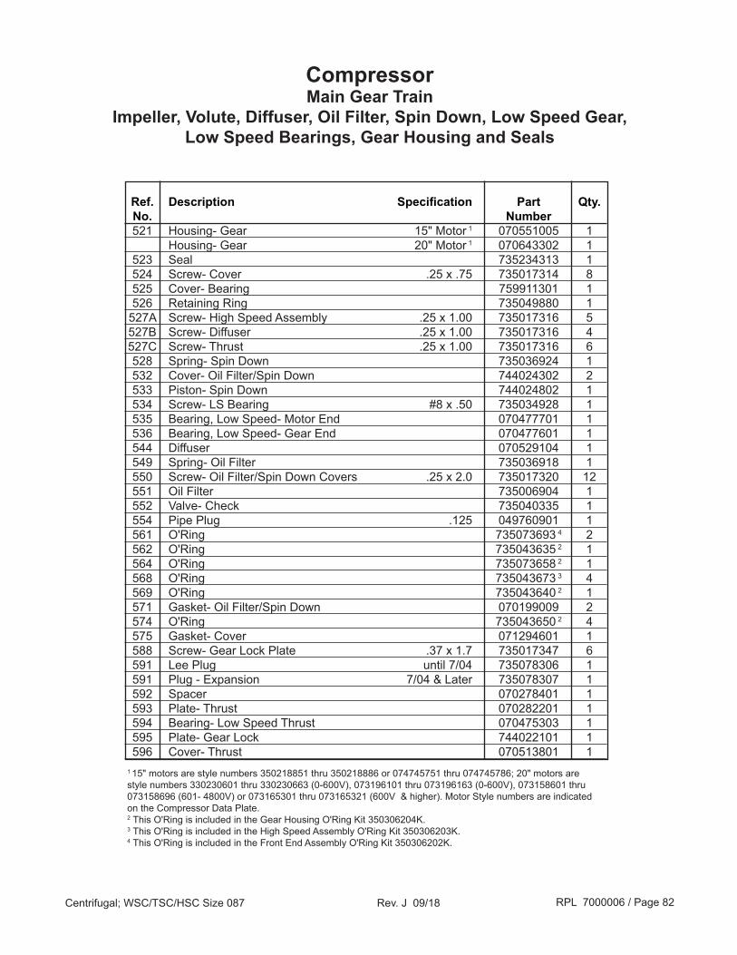
RPL 7000006 / Page 82Centrifugal; WSC/TSC/HSC Size 087 Rev. J 09/18
Ref. Description Specification Part Qty. No. Number 521 Housing- Gear 15" Motor 1 070551005 1 Housing- Gear 20" Motor 1 070643302 1 523 Seal 735234313 1 524 Screw- Cover .25 x .75 735017314 8 525 Cover- Bearing 759911301 1 526 Retaining Ring 735049880 1 527A Screw- High Speed Assembly .25 x 1.00 735017316 5 527B Screw- Diffuser .25 x 1.00 735017316 4 527C Screw- Thrust .25 x 1.00 735017316 6 528 Spring- Spin Down 735036924 1 532 Cover- Oil Filter/Spin Down 744024302 2 533 Piston- Spin Down 744024802 1 534 Screw- LS Bearing #8 x .50 735034928 1 535 Bearing, Low Speed- Motor End 070477701 1 536 Bearing, Low Speed- Gear End 070477601 1 544 Diffuser 070529104 1 549 Spring- Oil Filter 735036918 1 550 Screw- Oil Filter/Spin Down Covers .25 x 2.0 735017320 12 551 Oil Filter 735006904 1 552 Valve- Check 735040335 1 554 Pipe Plug .125 049760901 1 561 O'Ring 735073693 4 2 562 O'Ring 735043635 2 1 564 O'Ring 735073658 2 1 568 O'Ring 735043673 3 4 569 O'Ring 735043640 2 1 571 Gasket- Oil Filter/Spin Down 070199009 2 574 O'Ring 735043650 2 4 575 Gasket- Cover 071294601 1 588 Screw- Gear Lock Plate .37 x 1.7 735017347 6 591 Lee Plug until 7/04 735078306 1 591 Plug - Expansion 7/04 & Later 735078307 1 592 Spacer 070278401 1 593 Plate- Thrust 070282201 1 594 Bearing- Low Speed Thrust 070475303 1 595 Plate- Gear Lock 744022101 1 596 Cover- Thrust 070513801 1
CompressorMain Gear Train
Impeller, Volute, Diffuser, Oil Filter, Spin Down, Low Speed Gear, Low Speed Bearings, Gear Housing and Seals
1 15" motors are style numbers 350218851 thru 350218886 or 074745751 thru 074745786; 20" motors are style numbers 330230601 thru 330230663 (0-600V), 073196101 thru 073196163 (0-600V), 073158601 thru 073158696 (601- 4800V) or 073165301 thru 073165321 (600V & higher). Motor Style numbers are indicated on the Compressor Data Plate.2 This O'Ring is included in the Gear Housing O'Ring Kit 350306204K.3 This O'Ring is included in the High Speed Assembly O'Ring Kit 350306203K.4 This O'Ring is included in the Front End Assembly O'Ring Kit 350306202K.

RPL 7000006 / Page 83Centrifugal; WSC/TSC/HSC Size 087 Rev. J 09/18
CompressorHigh Speed Assembly
Pinion, Thrust Pump, High Speed Bearings, Seals
429
421
469
421
414
423
416
413 415
466 437
460
466
466
438
469 418
410 426
463
455
427429
421
469
421
414
421
416
413
415
466437
460
466
466
438469
418
410 426
463
455
427
Current Design:10/03 and later
Original Design:Until 10/03
(italicized parts have changed and are no longer available. If any one of these are
required, all must be retrofitted)
NOTE:In late September, 2003 the rear high speed assembly was redesigned. Both designs are shown for reference, however only the current design may be used for replacement parts. The parts involved in the redesign are indicated in the Original Design diagram with italicized reference bubbles. Original and new design affected (italicized) parts DO NOT interchange, and older design parts are no longer available. Replacement of any of the affected parts on a unit built prior to 10/03 requires retrofitting the assembly with ALL redesigned parts.
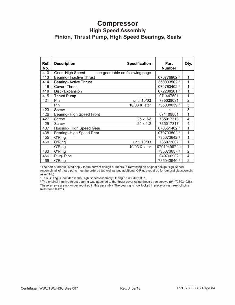
RPL 7000006 / Page 84Centrifugal; WSC/TSC/HSC Size 087 Rev. J 09/18
Ref. Description Specification Part Qty. No. Number 410 Gear- High Speed see gear table on following page 413 Bearing- Inactive Thrust 070776902 1 1 414 Bearing- Active Thrust 350093502 1 1 416 Cover- Thrust 074763402 1 1 418 Disc- Expansion 072288201 1 1 415 Thrust Pump 071447501 1 421 Pin until 10/03 735038031 2 Pin 10/03 & later 735038039 1 5 423 Screw 3 3 426 Bearing- High Speed Front 071409801 1 427 Screw .25 x .62 735017313 4 429 Screw .25 x 1.2 735017317 4 437 Housing- High Speed Gear 070551402 1 1 438 Bearing- High Speed Rear 070703502 1 1 455 O'Ring 735073642 2 1 460 O'Ring until 10/03 735073607 1 O'Ring 10/03 & later 070194987 1, 2 1 463 O'Ring 735073657 2 2 466 Plug- Pipe 049760902 4 469 O'Ring 735043640 2 21 The part numbers listed apply to the current design numbers. If retrofitting an original design High Speed Assembly all of these parts must be ordered (as well as any additional O'Rings required for general disassembly/assembly).2 This O'Ring is included in the High Speed Assembly O'Ring Kit 350306203K.3 The original inactive thrust bearing was attached to the thrust cover using these three screws (p/n 735034928). These screws are no longer required in this assembly. The bearing is now locked in place using three roll pins (reference # 421).
CompressorHigh Speed Assembly
Pinion, Thrust Pump, High Speed Bearings, Seals

RPL 7000006 / Page 85Centrifugal; WSC/TSC/HSC Size 087 Rev. J 09/18
CompressorGears- High Speed (Pinion) & Low Speed (Bull)
Gear High Speed Low Speed Code Pinion Gear Bull Gear AC 071889642 776123242 AD 071889643 776123243 AE 071889644 776123244 AF 071889645 776123245 AG 071889646 776123246 AH 071889647 776123247 AJ 071889648 776123248 AK 071889649 776123249 AL 071889650 776123250 AM 071889673 776123273 AN 071889674 776123274 AP 071889675 776123275 AQ 071889651 776123251 AR 071889652 776123252 AS 071889653 776123253 AT 071889654 776123254 AU 071889655 776123255 AV 071889656 776123256 AW 071889657 776123257 A2 071889658 776123258 AY 071889659 776123259 AZ 071889660 776123260 BA 071889661 776123261 BB 071889662 776123262 BC 071889663 776123263 BD 071889664 776123264 BE 071889665 776123265 BF 071889666 776123266 BG 071889667 776123267 BH 071889668 776123268
CompressorO'Ring Kits
Application Kit Number Front End (IGV) 350306202K High Speed Assembly 350306203K Main Gear Housing 350306204K Motor Housing- 15" 350306205K Motor Housing- 20" 350306206K
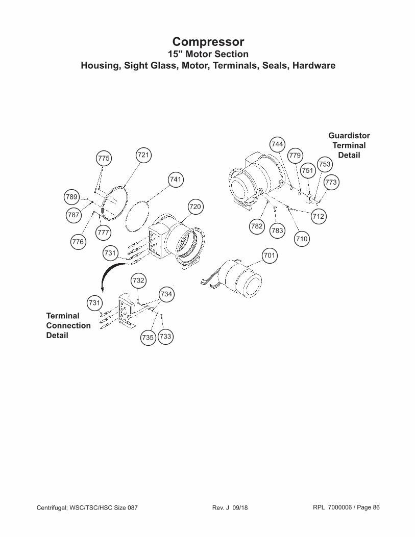
RPL 7000006 / Page 86Centrifugal; WSC/TSC/HSC Size 087 Rev. J 09/18
Compressor15" Motor Section
Housing, Sight Glass, Motor, Terminals, Seals, Hardware
731
731
Terminal Connection Detail
Guardistor Terminal
Detail
734
735 733
701
776777
787
775 721
741
720
732
789
744779
751753
773
782 783710
712

RPL 7000006 / Page 87Centrifugal; WSC/TSC/HSC Size 087 Rev. J 09/18
Ref. Description Specification Part Qty. No. Number 701 Stator 1 see motor tables on following pages 710 Fitting- Straight Thread 4, 5 Service Tool 070789308 1 712 Cap- Fitting 5 070789312 1 720 Housing- 15" Motor 074891702 1 721 Cover, End- Motor Housing 070677801 1 731 Terminal- Motor 074608102 6 6 732 Screw- Terminal .37 x 1.2 735033233 6 733 Nut- Terminal .37-16 040499906 6 734 Washer, Flat- Terminal 040500316 12 735 Washer, Lock- Terminal 048164812 6 741 O'Ring- End Cover 735043638 2 1 744 O'Ring 735073635 2 1 751 Box- Electrical 330763801 1 753 Washer- Lock 048164806 3 4 773 Screw #10 x .62 735036446 3 4 775 Sight Glass- End Cover 015997816 2 776 Screw- End Cover .37 x 1.5 735033435 16 777 Washer, Lock- End Cover 048164812 16 779 Terminal- 4 Pin 070260802 1 782 Dowel 735068004 1 783 Plug w/O'Ring 735017101 1 787 Orifice Fitting Motor Drain Conn. 070789304 1 789 Cap- Orifice Fitting Service Tool 070789311 1
Compressor15" Motor Section
Motor Styles: 0747457XX or 3502188XXHousing, Sight Glass, Motor, Terminals, Seals, Hardware
1 See Gear Housing Section for location of rotor/shaft assembly.2 This O'Ring is included in the 15" Motor Housing Assembly O'Ring Kit 350306205K.3 Units built prior to 2/03 used a ½" screw p/n 735036445 and no lock washers.4 Motor Cooling line flange connects here. 5 Prior to 4/05 there was a 2 bolt flange installed here. Which included (1) Flange p/n 735055221, (1) Gasket p/n 070199011, and (2) Screw p/n 735017345.6 Part number 074608103 may also be used.

RPL 7000006 / Page 88Centrifugal; WSC/TSC/HSC Size 087 Rev. J 09/18
Compressor15" Motor Section
Motors Style 0747457XX- Stators, Rotor/Shaft Assembly Ref. Motor Motor Motor Motor Stator Rotor/ No. Code 1 Voltage H.P. P.N. Part No. Shaft Assy 2
701 16E 220/50 154 074745751 074745801 074855751 16Y 346/50 154 074745752 074745802 074855751 18U 380/60 185 074745752 074745802 074855751 16H 440/50 154 074745753 074745803 074855751 18N 200/60 185 074745754 074745804 074855751 18B 208/60 185 074745754 074745804 074855751 18P 220/60 185 074745755 074745805 074855751 18V 230/60 185 074745755 074745805 074855751 18W 240/60 185 074745755 074745805 074855751 16F 380/50 154 074745756 074745806 074855751 16G 400/50 154 074745756 074745806 074855751 16K 415/50 154 074745756 074745806 074855751 18A 440/60 185 074745756 074745806 074855751 18R 460/60 185 074745756 074745806 074855751 18S 480/60 185 074745756 074745806 074855751 18D 575/60 185 074745757 074745807 074855751 18E 220/50 192 074745758 074745808 074855752 18Y 346/50 192 074745759 074745809 074855752 23U 380/60 230 074745759 074745809 074855752 18H 440/50 192 074745760 074745810 074855752 23N 200/60 230 074745761 074745811 074855752 23B 208/60 230 074745761 074745811 074855752 23P 220/60 230 074745762 074745812 074855752 23V 230/60 230 074745762 074745812 074855752 23W 240/60 230 074745762 074745812 074855752 18F 380/50 192 074745763 074745813 074855752 18G 400/50 192 074745763 074745813 074855752 18K 415/50 192 074745763 074745813 074855752 23A 440/60 230 074745763 074745813 074855752 23R 460/60 230 074745763 074745813 074855752 23S 480/60 230 074745763 074745813 074855752 23D 575/60 230 074745764 074745814 074855752 23E 220/50 242 074745765 074745815 074855753 23Y 346/50 242 074745766 074745816 074855753 29U 380/60 290 074745766 074745816 074855753 23H 440/50 242 074745767 074745817 074855753 29N 200/60 290 074745768 074745818 074855753 29B 208/60 290 074745768 074745818 074855753 29P 220/60 290 074745769 074745819 074855753 29V 230/60 290 074745769 074745819 074855753 29W 240/60 290 074745769 074745819 074855753 23F 380/50 242 074745770 074745820 074855753 23G 400/50 242 074745770 074745820 074855753 23K 415/50 242 074745770 074745820 074855753 29A 440/60 290 074745770 074745820 074855753 29R 460/60 290 074745770 074745820 074855753 29S 480/60 290 074745770 074745820 074855753 29D 575/60 290 074745771 074745821 0748557531 Digits 9, 10, 11 in compressor model number. 2 Rotor and Low Speed Shaft shrunk fit together.

RPL 7000006 / Page 89Centrifugal; WSC/TSC/HSC Size 087 Rev. J 09/18
Compressor15" Motor Section
Motors Style 0747457XX- Stators, Rotor/Shaft Assembly
Ref. Motor Motor Motor Motor Stator Rotor/ No. Code 1 Voltage H.P. P.N. Part No. Shaft Assy 2
701 29E 220/50 292 074745772 074745872 074855754 29Y 346/50 292 074745773 074745873 074855754 35U 380/60 350 074745773 074745873 074855754 29H 440/50 292 074745774 074745874 074855754 35N 200/60 350 074745775 074745875 074855754 35B 208/60 350 074745775 074745875 074855754 35P 220/60 350 074745776 074745876 074855754 35V 230/60 350 074745776 074745876 074855754 35W 240/60 350 074745776 074745876 074855754 29F 380/50 292 074745777 074745877 074855754 29G 400/50 292 074745777 074745877 074855754 29K 415/50 292 074745777 074745877 074855754 35A 440/60 350 074745777 074745877 074855754 35R 460/60 350 074745777 074745877 074855754 35S 480/60 350 074745777 074745877 074855754 35D 575/60 350 074745778 074745878 074855754 35E 220/50 333 074745779 074745879 074855755 35Y 346/50 333 074745780 074745880 074855755 40U 380/60 400 074745780 074745880 074855755 35H 440/50 333 074745781 074745881 074855755 40N 200/60 400 074745782 074745882 074855755 40B 208/60 400 074745782 074745882 074855755 40P 220/60 400 074745783 074745883 074855755 40V 230/60 400 074745783 074745883 074855755 40W 240/60 400 074745783 074745883 074855755 35F 380/50 333 074745784 074745884 074855755 35G 400/50 333 074745784 074745884 074855755 35K 415/50 333 074745784 074745884 074855755 40A 440/60 400 074745784 074745884 074855755 40R 460/60 400 074745784 074745884 074855755 40S 480/60 400 074745784 074745884 074855755 40D 575/60 400 074745785 074745885 074855755 40Q 416/60 400 074745786 074745886 0748557551 Digits 9, 10, 11 in compressor model number. 2 Rotor and Low Speed Shaft shrunk fit together.

RPL 7000006 / Page 90Centrifugal; WSC/TSC/HSC Size 087 Rev. J 09/18
Compressor15" Motor Section
Motors Style 3502188XX- Stators, Rotor/Shaft Assembly Ref. Motor Motor Motor Motor Stator Rotor/ No. Code 1 Voltage H.P. P.N. Part No. Shaft Assy 2
701 16E 220/50 154 350218851 350218901 350283251 16Y 346/50 154 350218852 350218902 350283251 18U 380/60 185 350218852 350218902 350283251 16H 440/50 154 350218853 350218903 350283251 18N 200/60 185 350218854 350218904 350283251 18B 208/60 185 350218854 350218904 350283251 18P 220/60 185 350218855 350218905 350283251 18V 230/60 185 350218855 350218905 350283251 18W 240/60 185 350218855 350218905 350283251 16F 380/50 154 350218856 350218906 350283251 16G 400/50 154 350218856 350218906 350283251 16K 415/50 154 350218856 350218906 350283251 18A 440/60 185 350218856 350218906 350283251 18R 460/60 185 350218856 350218906 350283251 18S 480/60 185 350218856 350218906 350283251 18D 575/60 185 350218857 350218907 350283251 18E 220/50 192 350218858 350218908 350283252 18Y 346/50 192 350218859 350218909 350283252 23U 380/60 230 350218859 350218909 350283252 18H 440/50 192 350218860 350218910 350283252 23N 200/60 230 350218861 350218911 350283252 23B 208/60 230 350218861 350218911 350283252 23P 220/60 230 350218862 350218912 350283252 23V 230/60 230 350218862 350218912 350283252 23W 240/60 230 350218862 350218912 350283252 18F 380/50 192 350218863 350218913 350283252 18G 400/50 192 350218863 350218913 350283252 18K 415/50 192 350218863 350218913 350283252 23A 440/60 230 350218863 350218913 350283252 23R 460/60 230 350218863 350218913 350283252 23S 480/60 230 350218863 350218913 350283252 23D 575/60 230 350218864 350218914 350283252 23E 220/50 242 350218865 350218915 350283253 23Y 346/50 242 350218866 350218916 350283253 29U 380/60 290 350218866 350218916 350283253 23H 440/50 242 350218867 350218917 350283253 29N 200/60 290 350218868 350218918 350283253 29B 208/60 290 350218868 350218918 350283253 29P 220/60 290 350218869 350218919 350283253 29V 230/60 290 350218869 350218919 350283253 29W 240/60 290 350218869 350218919 350283253 23F 380/50 242 350218870 350218920 350283253 23G 400/50 242 350218870 350218920 350283253 23K 415/50 242 350218870 350218920 350283253 29A 440/60 290 350218870 350218920 350283253 29R 460/60 290 350218870 350218920 350283253 29S 480/60 290 350218870 350218920 350283253 29D 575/60 290 350218871 350218921 3502832531 Digits 9, 10, 11 in compressor model number. 2 Rotor and Low Speed Shaft shrunk fit together.

RPL 7000006 / Page 91Centrifugal; WSC/TSC/HSC Size 087 Rev. J 09/18
Compressor15" Motor Section
Motors Style 3502188XX- Stators, Rotor/Shaft Assembly
Ref. Motor Motor Motor Motor Stator Rotor/ No. Code 1 Voltage H.P. P.N. Part No. Shaft Assy 2
701 29E 220/50 292 350218872 350218972 350283254 29Y 346/50 292 350218873 350218973 350283254 35U 380/60 350 350218873 350218973 350283254 29H 440/50 292 350218874 350218974 350283254 35N 200/60 350 350218875 350218975 350283254 35B 208/60 350 350218875 350218975 350283254 35P 220/60 350 350218876 350218976 350283254 35V 230/60 350 350218876 350218976 350283254 35W 240/60 350 350218876 350218976 350283254 29F 380/50 292 350218877 350218977 350283254 29G 400/50 292 350218877 350218977 350283254 29K 415/50 292 350218877 350218977 350283254 35A 440/60 350 350218877 350218977 350283254 35R 460/60 350 350218877 350218977 350283254 35S 480/60 350 350218877 350218977 350283254 35D 575/60 350 350218878 350218978 350283254 35E 220/50 333 350218879 350218979 350283255 35Y 346/50 333 350218880 350218980 350283255 40U 380/60 400 350218880 350218980 350283255 35H 440/50 333 350218881 350218981 350283255 40N 200/60 400 350218882 350218982 350283255 40B 208/60 400 350218882 350218982 350283255 40P 220/60 400 350218883 350218983 350283255 40V 230/60 400 350218883 350218983 350283255 40W 240/60 400 350218883 350218983 350283255 35F 380/50 333 350218884 350218984 350283255 35G 400/50 333 350218884 350218984 350283255 35K 415/50 333 350218884 350218984 350283255 40A 440/60 400 350218884 350218984 350283255 40R 460/60 400 350218884 350218984 350283255 40S 480/60 400 350218884 350218984 350283255 40D 575/60 400 350218885 350218985 350283255 40Q 416/60 400 350218886 350218986 3502832551 Digits 9, 10, 11 in compressor model number. 2 Rotor and Low Speed Shaft shrunk fit together.

RPL 7000006 / Page 92Centrifugal; WSC/TSC/HSC Size 087 Rev. J 09/18
Compressor15" Motor Section
Motors Style 3307457XX- Stators, Rotor/Shaft Assembly Ref. Motor Motor Motor Motor Stator Rotor/ No. Code 1 Voltage H.P. P.N. Part No. Shaft Assy 2
701 23U 380/60 230 330745759 330745809 330746052 23N 200/60 230 330745761 330745811 330746052 23B 208/60 230 330745761 330745811 330746052 23P 220/60 230 330745762 330745812 330746052 23V 230/60 230 330745762 330745812 330746052 23W 240/60 230 330745762 330745812 330746052 23A 440/60 230 330745763 330745813 330746052 23R 460/60 230 330745763 330745813 330746052 23S 480/60 230 330745763 330745813 330746052 23D 575/60 230 330745764 330745814 330746052 23E 220/50 242 330745765 330745815 330746053 23Y 346/50 242 330745766 330745816 330746053 29U 380/60 290 330745766 330745816 330746053 23H 440/50 242 330745767 330745817 330746053 29N 200/60 290 330745768 330745818 330746053 29B 208/60 290 330745768 330745818 330746053 29P 220/60 290 330745769 330745819 330746053 29V 230/60 290 330745769 330745819 330746053 29W 240/60 290 330745769 330745819 330746053 23F 380/50 242 330745770 330745820 330746053 23G 400/50 242 330745770 330745820 330746053 23K 415/50 242 330745770 330745820 330746053 29A 440/60 290 330745770 330745820 330746053 29R 460/60 290 330745770 330745820 330746053 29S 480/60 290 330745770 330745820 330746053 29D 575/60 290 330745771 330745821 330746053 29E 220/50 292 330745772 330745872 330746054 29Y 346/50 292 330745773 330745873 330746054 35U 380/60 350 330745773 330745873 330746054 29H 440/50 292 330745774 330745874 330746054 35N 200/60 350 330745775 330745875 330746054 35B 208/60 350 330745775 330745875 330746054 35P 220/60 350 330745776 330745876 330746054 35V 230/60 350 330745776 330745876 330746054 35W 240/60 350 330745776 330745876 330746054 29F 380/50 292 330745777 330745877 330746054 29G 400/50 292 330745777 330745877 330746054 29K 415/50 292 330745777 330745877 330746054 35A 440/60 350 330745777 330745877 330746054 35R 460/60 350 330745777 330745877 330746054 35S 480/60 350 330745777 330745877 330746054 35D 575/60 350 330745778 330745878 330746054 35E 220/50 333 330745779 330745879 330746055 35Y 346/50 333 330745780 330745880 330746055 40U 380/60 400 330745780 330745880 330746055 35H 440/50 333 330745781 330745881 330746055 40N 200/60 400 330745782 330745882 330746055 40B 208/60 400 330745782 330745882 3307460551 Digits 9, 10, 11 in compressor model number. 2 Rotor and Low Speed Shaft shrunk fit together.

RPL 7000006 / Page 93Centrifugal; WSC/TSC/HSC Size 087 Rev. J 09/18
Compressor15" Motor Section
Motors Style 3307457XX- Sta tors, Rotor/Shaft Assembly
Ref. Motor Motor Motor Motor Stator Rotor/ No. Code 1 Voltage H.P. P.N. Part No. Shaft Assy 2
701 40P 220/60 400 330745783 330745883 330746055 40V 230/60 400 330745783 330745883 330746055 40W 240/60 400 330745783 330745883 330746055 35F 380/50 333 330745784 330745884 330746055 35G 400/50 333 330745784 330745884 330746055 35K 415/50 333 330745784 330745884 330746055 40A 440/60 400 330745784 330745884 330746055 40R 460/60 400 330745784 330745884 330746055 40S 480/60 400 330745784 330745884 330746055 40D 575/60 400 330745785 330745885 330746055 40Q 416/60 400 330745786 330745886 3307460551 Digits 9, 10, 11 in compressor model number. 2 Rotor and Low Speed Shaft shrunk fit together.

RPL 7000006 / Page 94Centrifugal; WSC/TSC/HSC Size 087 Rev. J 09/18
Compressor20" Motor Section
Housing, Sight Glass, Motor, Terminals, Seals, Hardware
631
631High
VoltageTerminal
Connection Detail
634
635 633
683
676
677
675 621
641
620
632
644
679
651
653 673
689
682
687
673
653
651679644
MediumVoltageTerminal
Connection Detail
LowVoltageTerminal
Connection Detail
631
640
638
636
601
or
or
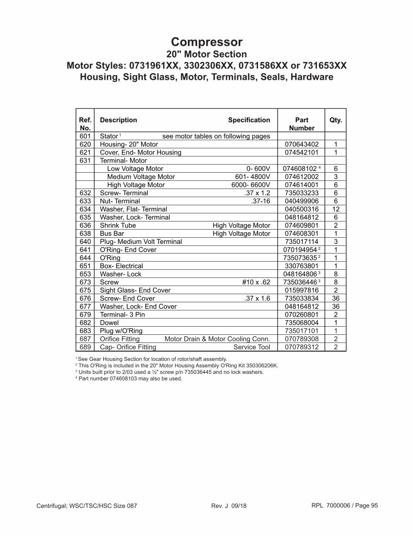
RPL 7000006 / Page 95Centrifugal; WSC/TSC/HSC Size 087 Rev. J 09/18
Compressor20" Motor Section
Motor Styles: 0731961XX, 3302306XX, 0731586XX or 731653XXHousing, Sight Glass, Motor, Terminals, Seals, Hardware
Ref. Description Specification Part Qty. No. Number 601 Stator 1 see motor tables on following pages 620 Housing- 20" Motor 070643402 1 621 Cover, End- Motor Housing 074542101 1 631 Terminal- Motor Low Voltage Motor 0- 600V 074608102 4 6 Medium Voltage Motor 601- 4800V 074612002 3 High Voltage Motor 6000- 6600V 074614001 6 632 Screw- Terminal .37 x 1.2 735033233 6 633 Nut- Terminal .37-16 040499906 6 634 Washer, Flat- Terminal 040500316 12 635 Washer, Lock- Terminal 048164812 6 636 Shrink Tube High Voltage Motor 074609801 2 638 Bus Bar High Voltage Motor 074608301 1 640 Plug- Medium Volt Terminal 735017114 3 641 O'Ring- End Cover 070194954 2 1 644 O'Ring 735073635 2 1 651 Box- Electrical 330763801 1 653 Washer- Lock 048164806 3 8 673 Screw #10 x .62 735036446 3 8 675 Sight Glass- End Cover 015997816 2 676 Screw- End Cover .37 x 1.6 735033834 36 677 Washer, Lock- End Cover 048164812 36 679 Terminal- 3 Pin 070260801 2 682 Dowel 735068004 1 683 Plug w/O'Ring 735017101 1 687 Orifice Fitting Motor Drain & Motor Cooling Conn. 070789308 2 689 Cap- Orifice Fitting Service Tool 070789312 21 See Gear Housing Section for location of rotor/shaft assembly.2 This O'Ring is included in the 20" Motor Housing Assembly O'Ring Kit 350306206K.3 Units built prior to 2/03 used a ½" screw p/n 735036445 and no lock washers.4 Part number 074608103 may also be used.
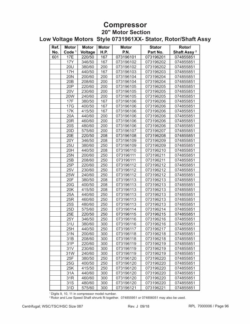
RPL 7000006 / Page 96Centrifugal; WSC/TSC/HSC Size 087 Rev. J 09/18
Compressor 20" Motor Section
Low Voltage Motors Style 0731961XX- Stator, Rotor/Shaft Assy Ref. Motor Motor Motor Motor Stator Rotor/ No. Code 1 Voltage H.P. P.N. Part No. Shaft Assy 2
601 17E 220/50 167 073196101 073196201 074855851 17Y 346/50 167 073196102 073196202 074855851 20U 380/60 200 073196102 073196202 074855851 17H 440/50 167 073196103 073196203 074855851 20N 200/60 200 073196104 073196204 074855851 20B 208/60 200 073196104 073196204 074855851 20P 220/60 200 073196105 073196205 074855851 20V 230/60 200 073196105 073196205 074855851 20W 240/60 200 073196105 073196205 074855851 17F 380/50 167 073196106 073196206 074855851 17G 400/50 167 073196106 073196206 074855851 17K 415/50 167 073196106 073196206 074855851 20A 440/60 200 073196106 073196206 074855851 20R 460/60 200 073196106 073196206 074855851 20S 480/60 200 073196106 073196206 074855851 20D 575/60 200 073196107 073196207 074855851 20E 220/50 208 073196108 073196208 074855851 20Y 346/50 208 073196109 073196209 074855851 25U 380/60 250 073196109 073196209 074855851 20H 440/50 208 073196110 073196210 074855851 25N 200/60 250 073196111 073196211 074855851 25B 208/60 250 073196111 073196211 074855851 25P 220/60 250 073196112 073196212 074855851 25V 230/60 250 073196112 073196212 074855851 25W 240/60 250 073196112 073196212 074855851 20F 380/50 208 073196113 073196213 074855851 20G 400/50 208 073196113 073196213 074855851 20K 415/50 208 073196113 073196213 074855851 25A 440/60 250 073196113 073196213 074855851 25R 460/60 250 073196113 073196213 074855851 25S 480/60 250 073196113 073196213 074855851 25D 575/60 250 073196114 073196214 074855851 25E 220/50 250 073196115 073196215 074855851 25Y 346/50 250 073196116 073196216 074855851 31U 380/60 300 073196116 073196216 074855851 25H 440/50 250 073196117 073196217 074855851 31N 200/60 300 073196118 073196218 074855851 31B 208/60 300 073196118 073196218 074855851 31P 220/60 300 073196119 073196219 074855851 31V 230/60 300 073196119 073196219 074855851 31W 240/60 300 073196119 073196219 074855851 25F 380/50 250 073196120 073196220 074855851 25G 400/50 250 073196120 073196220 074855851 25K 415/50 250 073196120 073196220 074855851 31A 440/60 300 073196120 073196220 074855851 31R 460/60 300 073196120 073196220 074855851 31S 480/60 300 073196120 073196220 074855851 31D 575/60 300 073196121 073196221 0748558511 Digits 9, 10, 11 in compressor model number. 2 Rotor and Low Speed Shaft shrunk fit together. 074855951 or 074856051 may also be used.

RPL 7000006 / Page 97Centrifugal; WSC/TSC/HSC Size 087 Rev. J 09/18
Compressor 20" Motor Section
Low Voltage Motors Style 0731961XX- Stator, Rotor/Shaft Assy Ref. Motor Motor Motor Motor Stator Rotor/ No. Code 1 Voltage H.P. P.N. Part No. Shaft Assy 2
601 31E 220/50 292 073196122 073196222 074855852 31Y 346/50 292 073196123 073196223 074855852 34U 380/60 350 073196123 073196223 074855852 31H 440/50 292 073196124 073196224 074855852 34N 200/60 350 073196125 073196225 074855852 34B 208/60 350 073196125 073196225 074855852 34P 234/60 350 073196126 073196226 074855852 34V 230/60 350 073196126 073196226 074855852 34W 240/60 350 073196126 073196226 074855852 31F 380/50 292 073196127 073196227 074855852 31G 400/50 292 073196127 073196227 074855852 31K 415/50 292 073196127 073196227 074855852 34A 440/60 350 073196127 073196227 074855852 34R 460/60 350 073196127 073196227 074855852 34S 480/60 350 073196127 073196227 074855852 34D 575/60 350 073196128 073196228 074855852 34E 220/50 333 073196129 073196229 074855853 34Y 346/50 333 073196130 073196230 074855853 41U 380/60 400 073196130 073196230 074855853 34H 440/50 333 073196131 073196231 074855853 41N 200/60 400 073196132 073196232 074855853 41B 208/60 400 073196132 073196232 074855853 41P 234/60 400 073196133 073196233 074855853 41V 230/60 400 073196133 073196233 074855853 41W 240/60 400 073196133 073196233 074855853 34F 380/50 333 073196134 073196234 074855853 34G 400/50 333 073196134 073196234 074855853 34K 415/50 333 073196134 073196234 074855853 41A 440/60 400 073196134 073196234 074855853 41R 460/60 400 073196134 073196234 074855853 41S 480/60 400 073196134 073196234 074855853 41D 575/60 400 073196135 073196235 074855853 41E 220/50 375 073196136 073196236 074855853 41Y 346/50 375 073196137 073196237 074855853 47U 380/60 450 073196137 073196237 074855853 41H 440/50 375 073196138 073196238 074855853 47N 200/60 450 073196139 073196239 074855853 47B 208/60 450 073196139 073196239 074855853 47P 234/60 450 073196140 073196240 074855853 47V 230/60 450 073196140 073196240 074855853 47W 240/60 450 073196140 073196240 074855853 41F 380/50 375 073196141 073196241 074855853 41G 400/50 375 073196141 073196241 074855853 41K 415/50 375 073196141 073196241 074855853 47A 440/60 450 073196141 073196241 074855853 47R 460/60 450 073196141 073196241 074855853 47S 480/60 450 073196141 073196241 074855853 47D 575/60 450 073196142 073196242 0748558531 Digits 9, 10, 11 in compressor model number. 2 Rotor and Low Speed Shaft shrunk fit together. 074855952/53 or 074856052/53 may also be used.
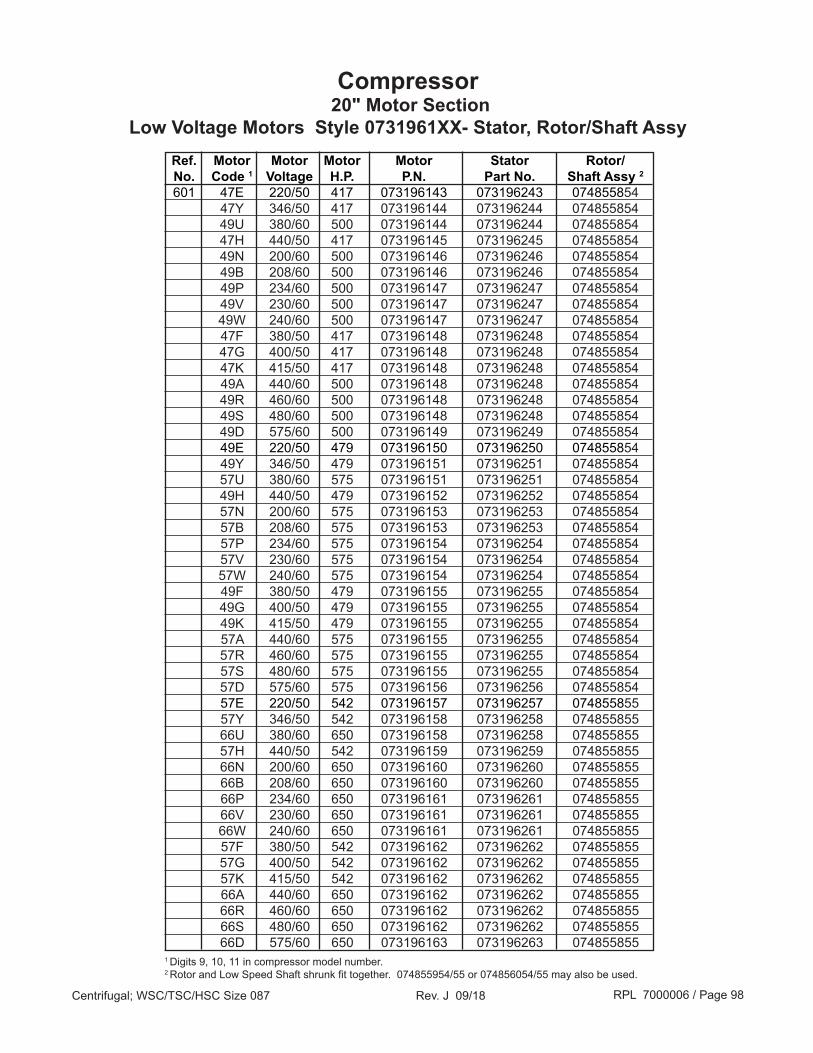
RPL 7000006 / Page 98Centrifugal; WSC/TSC/HSC Size 087 Rev. J 09/18
Compressor 20" Motor Section
Low Voltage Motors Style 0731961XX- Stator, Rotor/Shaft Assy Ref. Motor Motor Motor Motor Stator Rotor/ No. Code 1 Voltage H.P. P.N. Part No. Shaft Assy 2
601 47E 220/50 417 073196143 073196243 074855854 47Y 346/50 417 073196144 073196244 074855854 49U 380/60 500 073196144 073196244 074855854 47H 440/50 417 073196145 073196245 074855854 49N 200/60 500 073196146 073196246 074855854 49B 208/60 500 073196146 073196246 074855854 49P 234/60 500 073196147 073196247 074855854 49V 230/60 500 073196147 073196247 074855854 49W 240/60 500 073196147 073196247 074855854 47F 380/50 417 073196148 073196248 074855854 47G 400/50 417 073196148 073196248 074855854 47K 415/50 417 073196148 073196248 074855854 49A 440/60 500 073196148 073196248 074855854 49R 460/60 500 073196148 073196248 074855854 49S 480/60 500 073196148 073196248 074855854 49D 575/60 500 073196149 073196249 074855854 49E 220/50 479 073196150 073196250 074855854 49Y 346/50 479 073196151 073196251 074855854 57U 380/60 575 073196151 073196251 074855854 49H 440/50 479 073196152 073196252 074855854 57N 200/60 575 073196153 073196253 074855854 57B 208/60 575 073196153 073196253 074855854 57P 234/60 575 073196154 073196254 074855854 57V 230/60 575 073196154 073196254 074855854 57W 240/60 575 073196154 073196254 074855854 49F 380/50 479 073196155 073196255 074855854 49G 400/50 479 073196155 073196255 074855854 49K 415/50 479 073196155 073196255 074855854 57A 440/60 575 073196155 073196255 074855854 57R 460/60 575 073196155 073196255 074855854 57S 480/60 575 073196155 073196255 074855854 57D 575/60 575 073196156 073196256 074855854 57E 220/50 542 073196157 073196257 074855855 57Y 346/50 542 073196158 073196258 074855855 66U 380/60 650 073196158 073196258 074855855 57H 440/50 542 073196159 073196259 074855855 66N 200/60 650 073196160 073196260 074855855 66B 208/60 650 073196160 073196260 074855855 66P 234/60 650 073196161 073196261 074855855 66V 230/60 650 073196161 073196261 074855855 66W 240/60 650 073196161 073196261 074855855 57F 380/50 542 073196162 073196262 074855855 57G 400/50 542 073196162 073196262 074855855 57K 415/50 542 073196162 073196262 074855855 66A 440/60 650 073196162 073196262 074855855 66R 460/60 650 073196162 073196262 074855855 66S 480/60 650 073196162 073196262 074855855 66D 575/60 650 073196163 073196263 0748558551 Digits 9, 10, 11 in compressor model number. 2 Rotor and Low Speed Shaft shrunk fit together. 074855954/55 or 074856054/55 may also be used.

RPL 7000006 / Page 99Centrifugal; WSC/TSC/HSC Size 087 Rev. J 09/18
Compressor 20" Motor Section
Low Voltage Motors Style 3302306XX- Stator, Rotor/Shaft Assy Ref. Motor Motor Motor Motor Stator Rotor/ No. Code 1 Voltage H.P. P.N. Part No. Shaft Assy 2
601 31E 220/50 292 330230622 330230722 330230952 31Y 346/50 292 330230623 330230723 330230952 34U 380/60 350 330230623 330230723 330230952 31H 440/50 292 330230624 330230724 330230952 34N 200/60 350 330230625 330230725 330230952 34B 208/60 350 330230625 330230725 330230952 34P 234/60 350 330230626 330230726 330230952 34V 230/60 350 330230626 330230726 330230952 34W 240/60 350 330230626 330230726 330230952 31F 380/50 292 330230627 330230727 330230952 31G 400/50 292 330230627 330230727 330230952 31K 415/50 292 330230627 330230727 330230952 34A 440/60 350 330230627 330230727 330230952 34R 460/60 350 330230627 330230727 330230952 34S 480/60 350 330230627 330230727 330230952 34D 575/60 350 330230628 330230728 330230952 34E 220/50 333 330230629 330230729 330230953 34Y 346/50 333 330230630 330230730 330230953 41U 380/60 400 330230630 330230730 330230953 34H 440/50 333 330230631 330230731 330230953 41N 200/60 400 330230632 330230732 330230953 41B 208/60 400 330230632 330230732 330230953 41P 234/60 400 330230633 330230733 330230953 41V 230/60 400 330230633 330230733 330230953 41W 240/60 400 330230633 330230733 330230953 34F 380/50 333 330230634 330230734 330230953 34G 400/50 333 330230634 330230734 330230953 34K 415/50 333 330230634 330230734 330230953 41A 440/60 400 330230634 330230734 330230953 41R 460/60 400 330230634 330230734 330230953 41S 480/60 400 330230634 330230734 330230953 41D 575/60 400 330230635 330230735 330230953 41E 220/50 375 330230636 330230736 330230953 41Y 346/50 375 330230637 330230737 330230953 47U 380/60 450 330230637 330230737 330230953 41H 440/50 375 330230638 330230738 330230953 47N 200/60 450 330230639 330230739 330230953 47B 208/60 450 330230639 330230739 330230953 47P 234/60 450 330230640 330230740 330230953 47V 230/60 450 330230640 330230740 330230953 47W 240/60 450 330230640 330230740 330230953 41F 380/50 375 330230641 330230741 330230953 41G 400/50 375 330230641 330230741 330230953 41K 415/50 375 330230641 330230741 330230953 47A 440/60 450 330230641 330230741 330230953 47R 460/60 450 330230641 330230741 330230953 47S 480/60 450 330230641 330230741 330230953 47D 575/60 450 330230642 330230742 3302309531 Digits 9, 10, 11 in compressor model number. 2 Rotor and Low Speed Shaft shrunk fit together.

RPL 7000006 / Page 100Centrifugal; WSC/TSC/HSC Size 087 Rev. J 09/18
Ref. Motor Motor Motor Motor Stator Rotor/ No. Code 1 Voltage H.P. P.N. Part No. Shaft Assy 2
601 47E 220/50 417 330230643 330230743 330230954 47Y 346/50 417 330230644 330230744 330230954 49U 380/60 500 330230644 330230744 330230954 47H 440/50 417 330230645 330230745 330230954 49N 200/60 500 330230646 330230746 330230954 49B 208/60 500 330230646 330230746 330230954 49P 234/60 500 330230647 330230747 330230954 49V 230/60 500 330230647 330230747 330230954 49W 240/60 500 330230647 330230747 330230954 47F 380/50 417 330230648 330230748 330230954 47G 400/50 417 330230648 330230748 330230954 47K 415/50 417 330230648 330230748 330230954 49A 440/60 500 330230648 330230748 330230954 49R 460/60 500 330230648 330230748 330230954 49S 480/60 500 330230648 330230748 330230954 49D 575/60 500 330230649 330230749 330230954 49E 220/50 479 330230650 330230750 330230954 49Y 346/50 479 330230651 330230751 330230954 57U 380/60 575 330230651 330230751 330230954 49H 440/50 479 330230652 330230752 330230954 57N 200/60 575 330230653 330230753 330230954 57B 208/60 575 330230653 330230753 330230954 57P 234/60 575 330230654 330230754 330230954 57V 230/60 575 330230654 330230754 330230954 57W 240/60 575 330230654 330230754 330230954 49F 380/50 479 330230655 330230755 330230954 49G 400/50 479 330230655 330230755 330230954 49K 415/50 479 330230655 330230755 330230954 57A 440/60 575 330230655 330230755 330230954 57R 460/60 575 330230655 330230755 330230954 57S 480/60 575 330230655 330230755 330230954 57D 575/60 575 330230656 330230756 330230954 57E 220/50 542 330230657 330230757 330230955 57Y 346/50 542 330230658 330230758 330230955 66U 380/60 650 330230658 330230758 330230955 57H 440/50 542 330230659 330230759 330230955 66N 200/60 650 330230660 330230760 330230955 66B 208/60 650 330230660 330230760 330230955 66P 234/60 650 330230661 330230761 330230955 66V 230/60 650 330230661 330230761 330230955 66W 240/60 650 330230661 330230761 330230955 57F 380/50 542 330230662 330230762 330230955 57G 400/50 542 330230662 330230762 330230955 57K 415/50 542 330230662 330230762 330230955 66A 440/60 650 330230662 330230762 330230955 66R 460/60 650 330230662 330230762 330230955 66S 480/60 650 330230662 330230762 330230955 66D 575/60 650 330230663 330230763 3302309551 Digits 9, 10, 11 in compressor model number. 2 Rotor and Low Speed Shaft shrunk fit together.
Compressor 20" Motor Section
Low Voltage Motors Style 3302306XX- Stator, Rotor/Shaft Assy

RPL 7000006 / Page 101Centrifugal; WSC/TSC/HSC Size 087 Rev. J 09/18
Ref. Motor Motor Motor Motor Stator Rotor/ No. Code 1 Voltage H.P. P.N. Part No. Shaft Assy 2
601 193 2300/60 180 073158601 073158701 074855851 19M 2400/60 180 073158601 073158701 074855851 156 3000/50 150 073158602 073158702 074855851 19C 3300/60 180 073158603 073158703 074855851 19L 4160/60 180 073158604 073158704 074855852 15J 3300/50 150 073158604 073158704 074855852 213 2300/60 210 073158605 073158705 074855851 21M 2400/60 210 073158605 073158705 074855851 196 3000/50 180 073158606 073158706 074855851 21C 3300/60 210 073158607 073158707 074855851 21L 4160/60 210 073158608 073158708 074855852 19J 3300/50 180 073158608 073158708 074855852 253 2300/60 250 073158609 073158709 074855851 25M 2400/60 250 073158609 073158709 074855851 216 3000/50 210 073158610 073158710 074855851 25C 3300/60 250 073158611 073158711 074855851 25L 4160/60 250 073158612 073158712 074855852 21J 3300/50 210 073158612 073158712 074855852 323 2300/60 250 073158613 073158713 074855852 32M 2400/60 250 073158613 073158713 074855852 256 3000/50 210 073158614 073158714 074855852 32C 3300/60 250 073158615 073158715 074855852 32L 4160/60 250 073158616 073158716 074855852 25J 3300/50 210 073158616 073158716 074855852 413 2300/60 410 073158617 073158717 074855853 41M 2400/60 410 073158617 073158717 074855853 326 3000/50 340 073158618 073158718 074855853 41C 3300/60 410 073158619 073158719 074855853 41L 4160/60 410 073158620 073158720 074855853 32J 3300/50 340 073158620 073158720 074855853 503 2300/60 500 073158621 073158721 074855854 50M 2400/60 500 073158621 073158721 074855854 416 3000/50 415 073158622 073158722 074855854 50C 3300/60 500 073158623 073158723 074855854 50L 4160/60 500 073158624 073158724 074855854 41J 3300/50 415 073158624 073158724 074855854 583 2300/60 575 073158625 073158725 074855854 58M 2400/60 575 073158625 073158725 074855854 506 3000/50 480 073158626 073158726 074855854 58C 3300/60 575 073158627 073158727 074855854 58L 4160/60 575 073158628 073158728 074855854 50J 3300/50 480 073158628 073158728 074855854
1 Digits 9, 10, 11 in compressor model number. 2 Rotor and Low Speed Shaft shrunk fit together. 074855951 or 074856051 may also be used in place of 074855851; 074855952 or 074856052 may also be used in place of 074855852; 074855953 or 074856053 may also be used in place of 074855853; 074855954 or 074856054 may also be used in place of 074855854.
Compressor 20" Motor Section
Medium Voltage Motors Style 0731586XX- Stator, Rotor/Shaft Assy
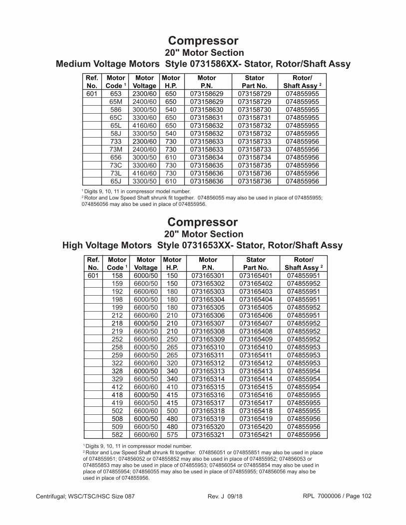
RPL 7000006 / Page 102Centrifugal; WSC/TSC/HSC Size 087 Rev. J 09/18
Ref. Motor Motor Motor Motor Stator Rotor/ No. Code 1 Voltage H.P. P.N. Part No. Shaft Assy 2
601 653 2300/60 650 073158629 073158729 074855955 65M 2400/60 650 073158629 073158729 074855955 586 3000/50 540 073158630 073158730 074855955 65C 3300/60 650 073158631 073158731 074855955 65L 4160/60 650 073158632 073158732 074855955 58J 3300/50 540 073158632 073158732 074855955 733 2300/60 730 073158633 073158733 074855956 73M 2400/60 730 073158633 073158733 074855956 656 3000/50 610 073158634 073158734 074855956 73C 3300/60 730 073158635 073158735 074855956 73L 4160/60 730 073158636 073158736 074855956 65J 3300/50 610 073158636 073158736 0748559561 Digits 9, 10, 11 in compressor model number. 2 Rotor and Low Speed Shaft shrunk fit together. 074856055 may also be used in place of 074855955; 074856056 may also be used in place of 074855956.
Compressor 20" Motor Section
Medium Voltage Motors Style 0731586XX- Stator, Rotor/Shaft Assy
1 Digits 9, 10, 11 in compressor model number. 2 Rotor and Low Speed Shaft shrunk fit together. 074856051 or 074855851 may also be used in place of 074855951; 074856052 or 074855852 may also be used in place of 074855952; 074856053 or 074855853 may also be used in place of 074855953; 074856054 or 074855854 may also be used in place of 074855954; 074856055 may also be used in place of 074855955; 074856056 may also be used in place of 074855956.
Compressor 20" Motor Section
High Voltage Motors Style 0731653XX- Stator, Rotor/Shaft Assy Ref. Motor Motor Motor Motor Stator Rotor/ No. Code 1 Voltage H.P. P.N. Part No. Shaft Assy 2
601 158 6000/50 150 073165301 073165401 074855951 159 6600/50 150 073165302 073165402 074855952 192 6600/60 180 073165303 073165403 074855951 198 6000/50 180 073165304 073165404 074855951 199 6600/50 180 073165305 073165405 074855952 212 6600/60 210 073165306 073165406 074855951 218 6000/50 210 073165307 073165407 074855952 219 6600/50 210 073165308 073165408 074855952 252 6600/60 250 073165309 073165409 074855952 258 6000/50 265 073165310 073165410 074855953 259 6600/50 265 073165311 073165411 074855953 322 6600/60 320 073165312 073165412 074855953 328 6000/50 340 073165313 073165413 074855954 329 6600/50 340 073165314 073165414 074855954 412 6600/60 410 073165315 073165415 074855954 418 6000/50 415 073165316 073165416 074855955 419 6600/50 415 073165317 073165417 074855955 502 6600/60 500 073165318 073165418 074855955 508 6000/50 480 073165319 073165419 074855956 509 6600/50 480 073165320 073165420 074855956 582 6600/60 575 073165321 073165421 074855956

RPL 7000006 / Page 103Centrifugal; WSC/TSC/HSC Size 087 Rev. J 09/18
Compressor 20" Motor Section
Low Voltage Motors Style 3306961XX- Stator, Rotor/Shaft Assy Ref. Motor Motor Motor Motor Stator Rotor/ No. Code 1 Voltage H.P. P.N. Part No. Shaft Assy 2
601 31E 220/50 292 330696122 330696222 330696452 31Y 346/50 292 330696123 330696223 330696452 34U 380/60 350 330696123 330696223 330696452 31H 440/50 292 330696124 330696224 330696452 34N 200/60 350 330696125 330696225 330696452 34B 208/60 350 330696125 330696225 330696452 34P 234/60 350 330696126 330696226 330696452 34V 230/60 350 330696126 330696226 330696452 34W 240/60 350 330696126 330696226 330696452 31F 380/50 292 330696127 330696227 330696452 31G 400/50 292 330696127 330696227 330696452 31K 415/50 292 330696127 330696227 330696452 34A 440/60 350 330696127 330696227 330696452 34R 460/60 350 330696127 330696227 330696452 34S 480/60 350 330696127 330696227 330696452 34D 575/60 350 330696128 330696228 330696452 34E 220/50 333 330696129 330696229 330696453 34Y 346/50 333 330696130 330696230 330696453 41U 380/60 400 330696130 330696230 330696453 34H 440/50 333 330696131 330696231 330696453 41N 200/60 400 330696132 330696232 330696453 41B 208/60 400 330696132 330696232 330696453 41P 234/60 400 330696133 330696233 330696453 41V 230/60 400 330696133 330696233 330696453 41W 240/60 400 330696133 330696233 330696453 34F 380/50 333 330696134 330696234 330696453 34G 400/50 333 330696134 330696234 330696453 34K 415/50 333 330696134 330696234 330696453 41A 440/60 400 330696134 330696234 330696453 41R 460/60 400 330696134 330696234 330696453 41S 480/60 400 330696134 330696234 330696453 41D 575/60 400 330696135 330696235 330696453 41E 220/50 375 330696136 330696236 330696453 41Y 346/50 375 330696137 330696237 330696453 47U 380/60 450 330696137 330696237 330696453 41H 440/50 375 330696138 330696238 330696453 47N 200/60 450 330696139 330696239 330696453 47B 208/60 450 330696139 330696239 330696453 47P 234/60 450 330696140 330696240 330696453 47V 230/60 450 330696140 330696240 330696453 47W 240/60 450 330696140 330696240 330696453 41F 380/50 375 330696141 330696241 330696453 41G 400/50 375 330696141 330696241 330696453 41K 415/50 375 330696141 330696241 330696453 47A 440/60 450 330696141 330696241 330696453 47R 460/60 450 330696141 330696241 330696453 47S 480/60 450 330696141 330696241 330696453 47D 575/60 450 330696142 330696242 3306964531 Digits 9, 10, 11 in compressor model number. 2 Rotor and Low Speed Shaft shrunk fit together.

RPL 7000006 / Page 104Centrifugal; WSC/TSC/HSC Size 087 Rev. J 09/18
Ref. Motor Motor Motor Motor Stator Rotor/ No. Code 1 Voltage H.P. P.N. Part No. Shaft Assy 2
601 47E 220/50 417 330696143 330696243 330696454 47Y 346/50 417 330696144 330696244 330696454 49U 380/60 500 330696144 330696244 330696454 47H 440/50 417 330696145 330696245 330696454 49N 200/60 500 330696146 330696246 330696454 49B 208/60 500 330696146 330696246 330696454 49P 234/60 500 330696147 330696247 330696454 49V 230/60 500 330696147 330696247 330696454 49W 240/60 500 330696147 330696247 330696454 47F 380/50 417 330696148 330696248 330696454 47G 400/50 417 330696148 330696248 330696454 47K 415/50 417 330696148 330696248 330696454 49A 440/60 500 330696148 330696248 330696454 49R 460/60 500 330696148 330696248 330696454 49S 480/60 500 330696148 330696248 330696454 49D 575/60 500 330696149 330696249 330696454 49E 220/50 479 330696150 330696250 330696454 49Y 346/50 479 330696151 330696251 330696454 57U 380/60 575 330696151 330696251 330696454 49H 440/50 479 330696152 330696252 330696454 57N 200/60 575 330696153 330696253 330696454 57B 208/60 575 330696153 330696253 330696454 57P 234/60 575 330696154 330696254 330696454 57V 230/60 575 330696154 330696254 330696454 57W 240/60 575 330696154 330696254 330696454 49F 380/50 479 330696155 330696255 330696454 49G 400/50 479 330696155 330696255 330696454 49K 415/50 479 330696155 330696255 330696454 57A 440/60 575 330696155 330696255 330696454 57R 460/60 575 330696155 330696255 330696454 57S 480/60 575 330696155 330696255 330696454 57D 575/60 575 330696156 330696256 330696454 57E 220/50 542 330696157 330696257 330696455 57Y 346/50 542 330696158 330696258 330696455 66U 380/60 650 330696158 330696258 330696455 57H 440/50 542 330696159 330696259 330696455 66N 200/60 650 330696160 330696260 330696455 66B 208/60 650 330696160 330696260 330696455 66P 234/60 650 330696161 330696261 330696455 66V 230/60 650 330696161 330696261 330696455 66W 240/60 650 330696161 330696261 330696455 57F 380/50 542 330696162 330696262 330696455 57G 400/50 542 330696162 330696262 330696455 57K 415/50 542 330696162 330696262 330696455 66A 440/60 650 330696162 330696262 330696455 66R 460/60 650 330696162 330696262 330696455 66S 480/60 650 330696162 330696262 330696455 66D 575/60 650 330696163 330696263 3306964551 Digits 9, 10, 11 in compressor model number. 2 Rotor and Low Speed Shaft shrunk fit together.
Compressor 20" Motor Section
Low Voltage Motors Style 3306961XX- Stator, Rotor/Shaft Assy
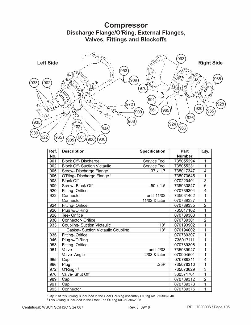
RPL 7000006 / Page 105Centrifugal; WSC/TSC/HSC Size 087 Rev. J 09/18
CompressorDischarge Flange/O'Ring, External Flanges,
Valves, Fittings and Blockoffs
935
922
Right Side
933 902
972
965905
901
908
909
Ref. Description Specification Part Qty. No. Number 901 Block Off- Discharge Service Tool 735055294 1 902 Block Off- Suction Victaulic Service Tool 735055231 1 905 Screw- Discharge Flange .37 x 1.7 735017347 4 906 O'Ring- Discharge Flange 2 735073645 1 908 Block Off 070220401 3 909 Screw- Block Off .50 x 1.5 735033847 6 920 Fitting- Orifice 070789304 4 922 Connector until 11/02 735031462 1 Connector 11/02 & later 070789337 1 924 Fitting- Orifice 070789335 2 926 Plug w/O'Ring 735017102 1 928 Tee- Orifice 070789303 1 930 Connector- Orifice 070789301 2 933 Coupling- Suction Victaulic 10" 070193902 1 Gasket- Suction Victaulic Coupling 10" 070194002 1 935 Fitting- Orifice 070789307 1 946 Plug w/O'Ring 735017111 1 953 Fitting- Orifice 070789308 1 961 Valve until 2/03 735039947 1 Valve- Angle 2/03 & later 070904501 1 965 Cap 070789311 4 966 Plug .25P 735078310 1 972 O'Ring 1, 2 735073629 3 976 Valve- Shut Off 330571701 1 989 Cap 070789312 2 991 Cap 070789373 1 993 Connector 070789375 11 Qty. 2 of this O'Ring is included in the Gear Housing Assembly O'Ring Kit 350306204K.2 This O'Ring is included in the Front End O'Ring Kit 350306202K.
928
965
976
991
965
924966
961
Left Side
906
946989
920
926
930
993
965
953
989

RPL 7000006 / Page 106Centrifugal; WSC/TSC/HSC Size 087 Rev. J 09/18
Compressor15" Motor Terminal Box- Free Standing Starter or VFD (Code 29-2= 5, L)
Units with MicroTech 200 Control Box
Surge Protection
Detail
901
Top View
Left View Right View
905 906
907854856
868
855
859854
864
871 872
869
850 858
888
871872
870
Ref. Description Specification Part Qty. No. Number 850 Cover- Electrical Box 000127300 1 854 Terminal Box 070533202 1 855 Screw- Terminal Box .25-20 x .5 046093807 6 856 Cover- Terminal Box 070533301 1 858 Screw- Electrical Box #10 x .37 735032742 2 859 Gasket 070199201 8 ft. 864 Insulation 047662050 * 868 Screw #10 x .5 735032843 12 869 Cable- Empty CC Heater 330006707 1 870 Cable- Empty CC Heater 330006706 1 871 Crankcase Heater 115V 300W 735041248 2 872 Fitting- Conduit 90° 000916900 2 888 Cable- Guardistor 070829989 1 901 Surge Capacitor 1 0- 480V 736017502 1 Surge Capacitor 1 481- 600V 736017503 1 905 Screw 1 #10- .50 735032743 1 906 Terminal 1 031015801 1 907 Terminal 1 735042840 3
1 Surge Capacitors are not used on units with Solid State Starters (Code 29-1= 6) or Variable Frequency Drives (Code 29-1= V).*Quantity in square feet, as needed.

RPL 7000006 / Page 107Centrifugal; WSC/TSC/HSC Size 087 Rev. J 09/18
Compressor15" Motor Terminal Box- Free Standing Starter or VFD (Code 29-2= 5, L)
Units with MicroTech II Control Box
Surge Protection
Detail
901
Top View
Left View Right View
905 906
907854856
868
855
859854
864
871 872
869
850 858
888
871872
870
895 891
897
892
894
896
893
896
854
Terminal Block Detail

RPL 7000006 / Page 108Centrifugal; WSC/TSC/HSC Size 087 Rev. J 09/18
Compressor15" Motor Terminal Box- Free Standing Starter or VFD (Code 29-2= 5, L)
Units with MicroTech II Control Box
Ref. Description Specification Part Qty. No. Number 850 Cover- Electrical Box 000127300 1 854 Terminal Box 0- 480V 330421101 1 Terminal Box 481- 600V 070533202 1 855 Screw- Terminal Box .25-20 x .5 046093807 6 856 Cover- Terminal Box 070533301 1 858 Screw- Electrical Box #10 x .37 735032742 2 859 Gasket 070199201 9 ft. 864 Insulation 047662050 * 868 Screw #10 x .5 735032843 12 869 Cable- Empty CC Heater 330006707 1 870 Cable- Empty CC Heater 330006706 1 871 Crankcase Heater 115V 300W 735041248 2 872 Fitting- Conduit 90° 000916900 2 888 Cable- Guardistor 070829989 1 891 Bracket- Terminal Block 330421001 1 892 Terminal Block 330274001 1 893 Cover- Terminal Block 330420901 1 894 Screw #8 x .37 735032729 2 895 Screw .25-20 x .5 040499023 4 896 Nut- Lock .25-20 032333302 4 897 Washer- Lock .25 040500208 4 901 Surge Capacitor 1 0- 480V 736017502 1 Surge Capacitor 1 481- 600V 736017503 1 905 Screw 1 #10- .50 735032743 1 906 Terminal 1 031015801 1 907 Terminal 1 735042840 3 N/S VFD Liquid Flo Parts Code 29-1= V only Switch- Oil Differential & Vane Close 071896001 1 Supply Tube 070789102 1 Fitting- Elbow 070789306 1 Fitting- Tee 070789303 1 Fitting- Swivel Connector 070789336 1 Fitting- Straight Connector 070789304 1
N/S= Not Shown on diagram.1 Surge Capacitors are not used on units with Solid State Starters (Code 29-1= 6) or Variable Frequency Drives (Code 29-1= V).*Quantity in square feet, as needed.

RPL 7000006 / Page 109Centrifugal; WSC/TSC/HSC Size 087 Rev. J 09/18
Compressor15" Motor Terminal Box- Unit Mounted Starter or VFD
(Code 29-2= 1, R, M)
Top ViewLeft View
Right View
854
864
871 872855
871872
869
Ref. Description Specification Part Qty. No. Number 850 Cover- Electrical Box 000127300 1 854 Shroud- Terminal 074746801 1 855 Screw- Terminal Box .25-20 x .5 046093807 6 858 Screw #10 x .37 735032742 4 859 Gasket 070199201 9 ft. 864 Insulation 047662050 * 869 Cable- Empty CC Heater 330006707 1 870 Cable- Empty CC Heater 330006706 1 871 Crankcase Heater 115V 300W 735041248 2 872 Fitting- Conduit 90° 000916900 2 888 Cable- Guardistor 070829989 1 N/S Surge Capacitor 1 0- 480V 736017502 1 Surge Capacitor 1 481- 600V 736017503 1 N/S VFD Liquid Flo Parts Code 29-1= V only Switch- Oil Differential & Vane Close 071896001 1 Supply Tube 070789102 1 Fitting- Elbow 070789306 1 Fitting- Tee 070789303 1 Fitting- Swivel Connector 070789336 1 Fitting- Straight Connector 070789304 1
870
850 858
888
N/S= Not Shown on diagram.1 Surge Capacitors are used on units with Direct Mount Starters (except for solid state starters code 29-1= 6). However, the capacitors are installed in the starter rather than the compressor terminal box.*Quantity in square feet, as needed.
854
859
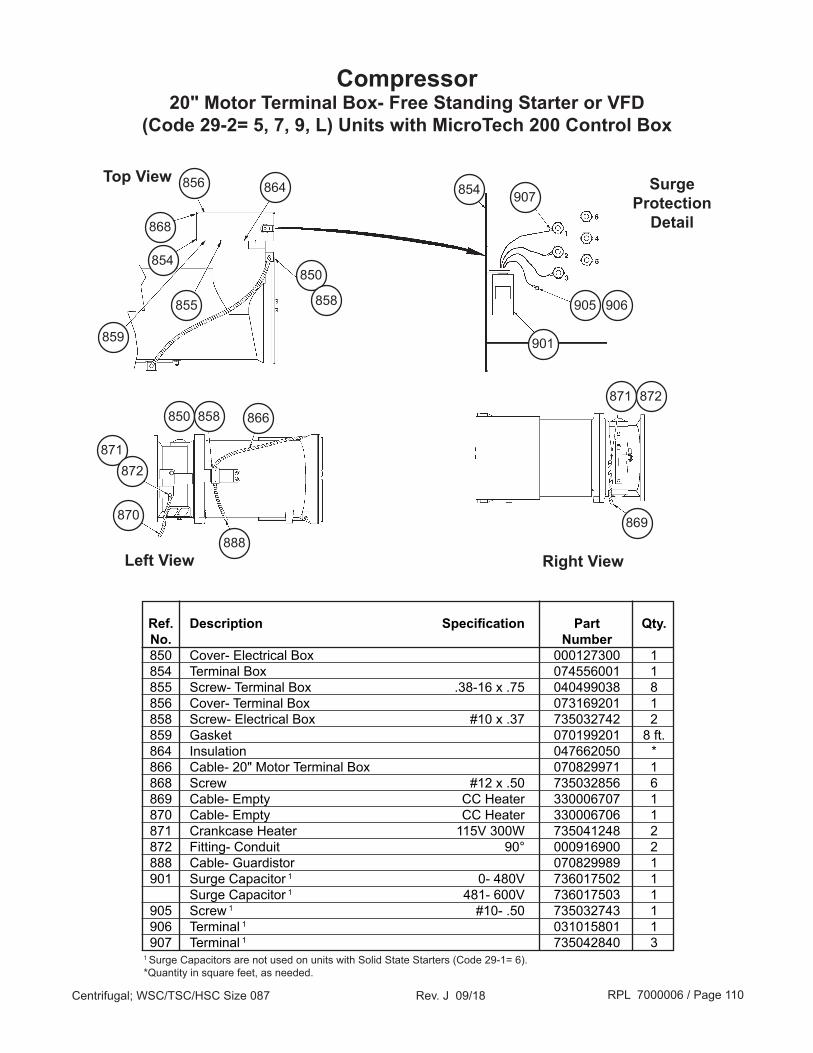
RPL 7000006 / Page 110Centrifugal; WSC/TSC/HSC Size 087 Rev. J 09/18
Compressor20" Motor Terminal Box- Free Standing Starter or VFD
(Code 29-2= 5, 7, 9, L) Units with MicroTech 200 Control Box
Surge Protection
Detail
901
Top View
Left View Right View
905 906
907854856
868
855
850854
858
871 872
869
850 858
888
871872
870
Ref. Description Specification Part Qty. No. Number 850 Cover- Electrical Box 000127300 1 854 Terminal Box 074556001 1 855 Screw- Terminal Box .38-16 x .75 040499038 8 856 Cover- Terminal Box 073169201 1 858 Screw- Electrical Box #10 x .37 735032742 2 859 Gasket 070199201 8 ft. 864 Insulation 047662050 * 866 Cable- 20" Motor Terminal Box 070829971 1 868 Screw #12 x .50 735032856 6 869 Cable- Empty CC Heater 330006707 1 870 Cable- Empty CC Heater 330006706 1 871 Crankcase Heater 115V 300W 735041248 2 872 Fitting- Conduit 90° 000916900 2 888 Cable- Guardistor 070829989 1 901 Surge Capacitor 1 0- 480V 736017502 1 Surge Capacitor 1 481- 600V 736017503 1 905 Screw 1 #10- .50 735032743 1 906 Terminal 1 031015801 1 907 Terminal 1 735042840 31 Surge Capacitors are not used on units with Solid State Starters (Code 29-1= 6).*Quantity in square feet, as needed.
866
859
864

RPL 7000006 / Page 111Centrifugal; WSC/TSC/HSC Size 087 Rev. J 09/18
Compressor20" Motor Terminal Box- Free Standing Starter or VFD
(Code 29-2= 5, 7, 9, L) Units with MicroTech II Control Box
895 891
897
892
894
896
893
896
854
Terminal Block Detail
Surge Protection
Detail
901
Top View
Left View Right View
905 906
907854856
868
855
850854
858
871 872
869
850 858
888
871872
870
866
859
864

RPL 7000006 / Page 112Centrifugal; WSC/TSC/HSC Size 087 Rev. J 09/18
Compressor20" Motor Terminal Box- Free Standing Starter or VFD
(Code 29-2= 5, 7, 9, L) Units with MicroTech II Control Box
Ref. Description Specification Part Qty. No. Number 850 Cover- Electrical Box 000127300 1 854 Terminal Box Standard Starter- Low Voltage until 3/03 330421201 1 Standard Starter- Low Voltage 3/03 & later 073169201 1 Standard Starter- Medium & High Voltage until 3/03 074556001 1 Standard Starter- Medium & High Voltage 3/03 & later 330549701 1 VFD 330421201 1 855 Screw- Terminal Box 040499038 8 856 Cover- Terminal Box 073169201 1 858 Screw- Electrical Box #10 x .37 735032742 2 859 Gasket 070199201 9 ft. 864 Insulation 047662050 * 866 Cable 070829971 1 868 Screw 735032856 6 869 Cable- Empty CC Heater 330006707 1 870 Cable- Empty CC Heater 330006706 1 871 Crankcase Heater 115V 300W 735041248 2 872 Fitting- Conduit 90° 000916900 2 888 Cable- Guardistor 070829989 1 891 Bracket 330421001 1 892 Terminal Block 330274001 1 893 Cover- Terminal Block 330420901 1 894 Screw #8 x .37 735032729 2 895 Screw .25-20 x .5 040499023 4 896 Nut- Lock .25-20 032333302 4 897 Washer- Lock .25 040500208 4 901 Surge Capacitor 1 481- 600V 736017503 1 Surge Capacitor 1 0- 480V 736017502 1 905 Screw 1 #10- .50 735032743 1 906 Terminal 1 031015801 1 907 Terminal 1 735042840 3 N/S VFD Liquid Flo Parts Code 29-1= V only Switch- Oil Differential & Vane Close 071896001 1 Supply Tube 070789102 1 Fitting- Elbow 070789306 1 Fitting- Tee 070789303 1 Fitting- Swivel Connector 070789336 1 Fitting- Straight Connector 070789304 1
N/S= Not Shown on diagram.1 Surge Capacitors apply to low voltage (0-600V) units only, and are not used on units with Solid State Starters (Code 29-1= 6).*Quantity in square feet, as needed.
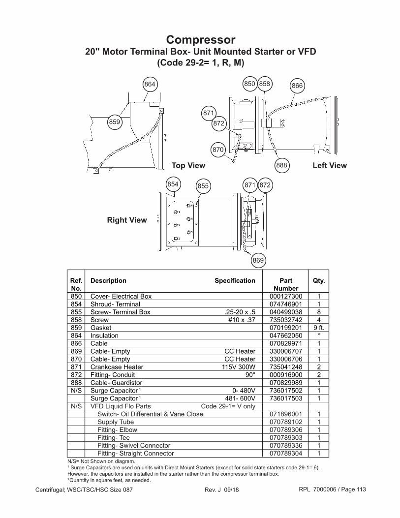
RPL 7000006 / Page 113Centrifugal; WSC/TSC/HSC Size 087 Rev. J 09/18
Compressor20" Motor Terminal Box- Unit Mounted Starter or VFD
(Code 29-2= 1, R, M)
Top View Left View
Right View
854
864
871 872855
871872
869
Ref. Description Specification Part Qty. No. Number 850 Cover- Electrical Box 000127300 1 854 Shroud- Terminal 074746901 1 855 Screw- Terminal Box .25-20 x .5 040499038 8 858 Screw #10 x .37 735032742 4 859 Gasket 070199201 9 ft. 864 Insulation 047662050 * 866 Cable 070829971 1 869 Cable- Empty CC Heater 330006707 1 870 Cable- Empty CC Heater 330006706 1 871 Crankcase Heater 115V 300W 735041248 2 872 Fitting- Conduit 90° 000916900 2 888 Cable- Guardistor 070829989 1 N/S Surge Capacitor 1 0- 480V 736017502 1 Surge Capacitor 1 481- 600V 736017503 1 N/S VFD Liquid Flo Parts Code 29-1= V only Switch- Oil Differential & Vane Close 071896001 1 Supply Tube 070789102 1 Fitting- Elbow 070789306 1 Fitting- Tee 070789303 1 Fitting- Swivel Connector 070789336 1 Fitting- Straight Connector 070789304 1
870
850 858
888
N/S= Not Shown on diagram.1 Surge Capacitors are used on units with Direct Mount Starters (except for solid state starters code 29-1= 6). However, the capacitors are installed in the starter rather than the compressor terminal box.*Quantity in square feet, as needed.
859
866

RPL 7000006 / Page 114Centrifugal; WSC/TSC/HSC Size 087 Rev. J 09/18
Oil PumpNomenclature
070019252
Assembly Part Number070019252= 14" Welded Steel Sump Oil Pump
350146601= 16" Cast & Machined Sump Oil Pump (w/MicroTech 200)350147201= 16" Cast & Machined Sump Oil Pump (w/ MicroTech II)
Style Number- Oil Pump
Oil Pump Dataplate- 14" Welded Steel Sump (pre 7/02)*
*This date is approximate. Oil pump data plate should be checked on any unit built between 9/01 and 7/02 to verify which oil pump is installed.
OilOil Charge= 8 Gallons
Oil Part Number (R134 units)= EAL46 p/n 735030435TSC units- Consult Daikin Applied
Oil Pump Dataplate- 16" Cast & Machined
Sump

RPL 7000006 / Page 115Centrifugal; WSC/TSC/HSC Size 087 Rev. J 09/18
Oil Pump16" Cast & Machined Sump Oil Pump
Supply and Vent Lines
Ref. Description Specification Part Qty. No. Number 20 Flange- 2 Bolt 074614801 1 21 O'Ring 735073629 1 22 Screw 735033846 2 30 Fitting- Sleeve 070789316 1 31 Fitting- Nut 070789310 1 41 Reducer 1.375 x .625 041116524 1 60 Schrader Valve 071100801 1 Schrader Valve Cap 032943500 1 Schrader Valve Core 026541100 1 120 Fitting- Sleeve 070789372 1 121 Fitting- Nut 070789373 1 140 Check Valve 735040326 1 180 Reducer .875 ODM x .625 ODS 041116611 2 202 Well 070809042 1
3031
41
60
2320 2221
120
121
180
140
202
180

RPL 7000006 / Page 116Centrifugal; WSC/TSC/HSC Size 087 Rev. J 09/18
Oil Pump16" Cast & Machined Sump Oil Pump
Oil Pump and Oil Cooler Piping and MountingUnits with MicroTech II Control
10
121
141
142
143
120
4041
42
1041
4250
30
54
260
210
201
141220
143142
203 204
233
232
231
230200
202
22
21
180 190
20
Oil Cooler Detail
122

RPL 7000006 / Page 117Centrifugal; WSC/TSC/HSC Size 087 Rev. J 09/18
Ref. Description Specification Part Qty. No. Number 10 Plate- Oil Pump/Oil Cooler Mounting 330285602 1 20 Oil Pump see following pages for detail 350147201 1 21 Sleeve- Orifice 070789351 1 22 Nut- Orifice 070789354 1 30 Bracket- Oil Pump 070014475 1 40 Screw .50 x 1.0 735033845 4 41 Washer- Plain .50 ZPS 040500311 8 42 Washer- Lock .50 ZPS 048164814 8 50 Screw .50 x 1.2 735033846 4 54 Nut .50-13 735029625 4 100 Tee 041117809 1 120 Oil Cooler 074666403 1 121 Spacer Pad- Upper 041763400 2 122 Washer- Plain .625 ZPS 040500312 2 141 Washer- Plain .375 040500308 4 142 Washer- Lock .375 048164812 4 143 Nut- Hex .375-16 040499906 4 180 Schrader Valve 071100801 1 Schrader Valve Cap 032943500 1 Schrader Valve Core 026541100 1 190 Schrader Valve 071100801 1 Schrader Valve Cap 032943500 1 Schrader Valve Core 026541100 1 200 Valve- Water Regulator, .75 Code 11= *4 (150 psig) 735075405 1 Valve- Water Regulator, .75 Code 11= *5 (300 psig) 759945107 1 201 Valve- Solenoid 735048470 1 202 Connector .88D x .75P 735043914 2 203 Nipple 735024590 2 204 Tee .75P x .75P x .75P 735031415 2 210 Bracket- Water Valve 330135801 1 220 Screw .375 x 1.25 735033833 2 230 U Bolt 330861101 2 231 Washer- Plain .312 ZPS 040500307 4 232 Washer- Lock .312 ZPS 040500210 4 233 Nut- Hex .312-18 040499904 4 260 Compressor Control Box See Controls Section
Oil Pump16" Cast & Machined Sump Oil Pump
Oil Pump and Oil Cooler Piping and MountingUnits with MicroTech II Control
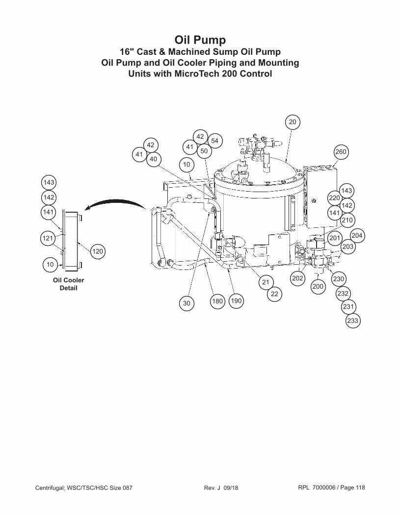
RPL 7000006 / Page 118Centrifugal; WSC/TSC/HSC Size 087 Rev. J 09/18
Oil Pump16" Cast & Machined Sump Oil Pump
Oil Pump and Oil Cooler Piping and MountingUnits with MicroTech 200 Control
10
121
141
142
143
120
4041
42
10
41 50
42
30
54
260
210
201
141
220143
142
203
204
233
232
231
230200
202
22
21
180 190
20
Oil Cooler Detail
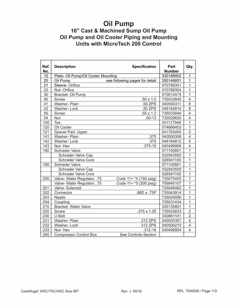
RPL 7000006 / Page 119Centrifugal; WSC/TSC/HSC Size 087 Rev. J 09/18
Oil Pump16" Cast & Machined Sump Oil Pump
Oil Pump and Oil Cooler Piping and MountingUnits with MicroTech 200 Control
Ref. Description Specification Part Qty. No. Number 10 Plate- Oil Pump/Oil Cooler Mounting 330189002 1 20 Oil Pump see following pages for detail 350146601 1 21 Sleeve- Orifice 070789351 1 22 Nut- Orifice 070789354 1 30 Bracket- Oil Pump 070014475 1 40 Screw .50 x 1.0 735033845 4 41 Washer- Plain .50 ZPS 040500311 8 42 Washer- Lock .50 ZPS 048164814 8 50 Screw .50 x 1.2 735033846 4 54 Nut .50-13 735029625 4 100 Tee 041117949 1 120 Oil Cooler 074666403 1 121 Spacer Pad- Upper 041763400 2 141 Washer- Plain .375 040500308 4 142 Washer- Lock .375 048164812 4 143 Nut- Hex .375-16 040499906 4 180 Schrader Valve 071100801 1 Schrader Valve Cap 032943500 1 Schrader Valve Core 026541100 1 190 Schrader Valve 071100801 1 Schrader Valve Cap 032943500 1 Schrader Valve Core 026541100 1 200 Valve- Water Regulator, .75 Code 11= *4 (150 psig) 735075405 1 Valve- Water Regulator, .75 Code 11= *5 (300 psig) 759945107 1 201 Valve- Solenoid 735048462 1 202 Connector .88D x .75P 735043914 1 203 Nipple 735024590 1 204 Coupling 735031434 1 210 Bracket- Water Valve 330135801 1 220 Screw .375 x 1.25 735033833 2 230 U Bolt 330861101 2 231 Washer- Plain .312 ZPS 040500307 4 232 Washer- Lock .312 ZPS 040500210 4 233 Nut- Hex .312-18 040499904 4 260 Compressor Control Box See Controls Section

RPL 7000006 / Page 120Centrifugal; WSC/TSC/HSC Size 087 Rev. J 09/18
Oil Pump16" Cast & Machined Sump Oil Pump Detail
234
230
232
350
352
See following page for sump interior detail
306 304302 312
316314 318
116
114
112
300
See following page for cover valves and fittings detail 226
228
218
212
214
220
224210
208
206202
200
Sump detail: 90° left
320
322

RPL 7000006 / Page 121Centrifugal; WSC/TSC/HSC Size 087 Rev. J 09/18
Oil Pump16" Cast & Machined Sump Oil Pump Detail
338 Cover Valves & Fittings
200
326
328
330
356
332338
334
Jet Pump Mounting
110
106
104
100

RPL 7000006 / Page 122Centrifugal; WSC/TSC/HSC Size 087 Rev. J 09/18
Ref. Description Specification Part Qty. No. Number Complete Oil Pump Assembly- Service 350147201S 4 1 100 Sump 071466602 1 104 O'Ring 070194966 1 2 106 Pump- Lube 070902501 1 110 Screw .62 x 1.0 735017344 4 112 O'Ring 735073635 1 1 114 Terminal- 3 Point 070260801 1 116 Screw #10 x .62 735036446 4 200 Cover 071466502 1 202 Pin- Roll .125 x .75 735038054 2 1 206 Plate- Filter Mounting 071467101 1 208 Filter Tube 735085708 4 210 O'Ring 070194902 1 1 212 O'Ring 735073615 1 1 214 Jet Pump 775208301 1 218 Cover- Filter 071467202 1 220 Plug .25 049760902 1 224 O'Ring 070194967 1 1 226 Screw .25 x 1.75 735033409 2 228 Screw .25 x 1.0 735033804 3 230 O'Ring 735043659 1 1 232 O'Ring 070194956 1 1 234 Bolt- Cover .25 x 2.5 735033851 15 300 Gauge- Liquid Level 330343801 1 302 Plug w/ O'Ring .88 735017109 1 304 Connector- Straight Thread 070789350 1 306 Valve- Angle 1.00 070904701 1 312 Heater- Crankcase 200W 735041227 2 314 Gasket- Terminal Box until 5/02 070906101 1 Gasket- Terminal Box 5/02 & later 330418601 1 316 Cover- Terminal Box until 5/02 070902601 1 Cover- Terminal Box 5/02 & later 330418701 1 318 Screw until 5/02 000011400 2 Screw 5/02 & later 000011400 4 320 Connector- Straight 070789308 1 322 Valve- Angle .625 073003701 1 326 Fitting- Rotolock 735044362 2 O'Ring- Rotolock Fitting 070194981 2 328 Seal Ring 736017605 2 330 Valve 1.38 735039953 2 332 Valve- Adjustable 735045843 1 334 Strainer 071467801 1 338 Plug- Ball 14mm 735078309 3 2 350 Sensor- Temperature (Microtech 200 units) 071568701 1 Sensor- Temperature (Microtech II units) 330198001 1 352 Cable- Temperature Sensor 330418501 1 356 Valve- Relief 200 PSI 735045818 11 This O'Ring is included in the 16" Oil Pump Assembly O'Ring Kit 350306212K.2 Pin is installed using the Roll Pin Insert Tool p/n 330418201.3 Ball Plug is installed using tool p/n 073259501.4 Complete assembly includes Oil Pump and Heaters (Qty. 2- part number 735041227).
Oil Pump16" Cast & Machined Sump Oil Pump Detail

RPL 7000006 / Page 123Centrifugal; WSC/TSC/HSC Size 087 Rev. J 09/18
Oil Pump14" Welded Steel Sump Oil Pump
Supply and Vent Lines
Ref. Description Specification Part Qty. No. Number 10 Fitting- Sleeve 070789316 2 11 Fitting- Nut 070789310 2 330 Reducer .875 ODM x .625 ODS 041116611 2 347 Check Valve 735040332 1 362 Screw .50 x 1.2 735033846 2 363 Flange- 2 Bolt 074614801 1 364 Reducer 1.375 ODS x .625 ODS 041116524 1 371 O'Ring 735073629 1
11
10
364
362363371
10
11
347
330
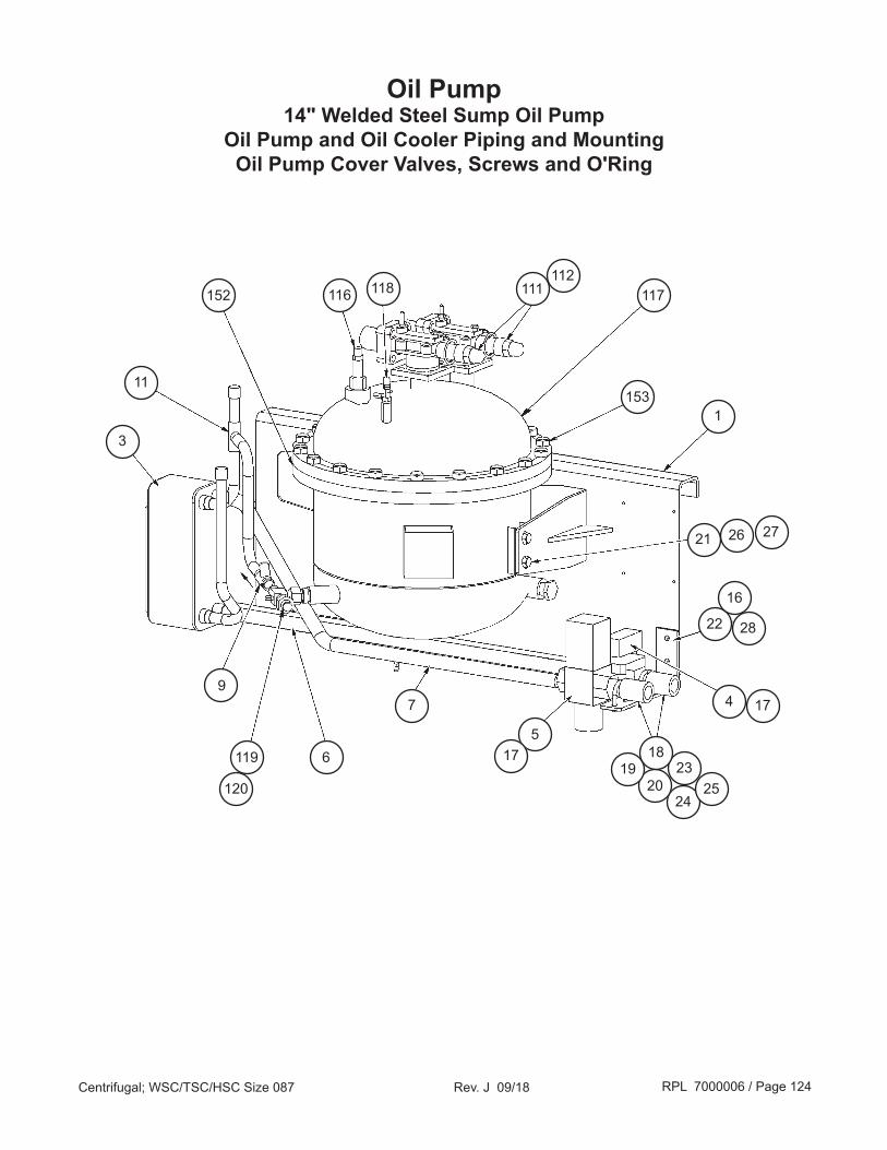
RPL 7000006 / Page 124Centrifugal; WSC/TSC/HSC Size 087 Rev. J 09/18
Oil Pump14" Welded Steel Sump Oil Pump
Oil Pump and Oil Cooler Piping and MountingOil Pump Cover Valves, Screws and O'Ring
152 111
11
3
118
6
116
119
7
517
2420
231918
25
117
1531
21 26 27
22
16
28
4 17
112
120
9
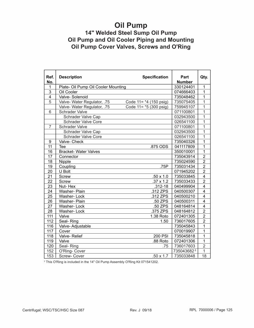
RPL 7000006 / Page 125Centrifugal; WSC/TSC/HSC Size 087 Rev. J 09/18
Ref. Description Specification Part Qty. No. Number 1 Plate- Oil Pump Oil Cooler Mounting 330124401 1 3 Oil Cooler 074666403 1 4 Valve- Solenoid 735048462 1 5 Valve- Water Regulator, .75 Code 11= *4 (150 psig) 735075405 1 Valve- Water Regulator, .75 Code 11= *5 (300 psig) 759945107 1 6 Schrader Valve 071100801 1 Schrader Valve Cap 032943500 1 Schrader Valve Core 026541100 1 7 Schrader Valve 071100801 1 Schrader Valve Cap 032943500 1 Schrader Valve Core 026541100 1 9 Valve- Check 735040326 1 11 Tee .875 ODS 041117809 1 16 Bracket- Water Valves 350010001 1 17 Connector 735043914 2 18 Nipple 735024590 2 19 Coupling .75P 735031434 2 20 U Bolt 071945202 2 21 Screw .50 x 1.0 735033845 4 22 Screw .37 x 1.2 735033433 2 23 Nut- Hex .312-18 040499904 4 24 Washer- Plain .312 ZPS 040500307 4 25 Washer- Lock .312 ZPS 040500210 4 26 Washer- Plain .50 ZPS 040500311 4 27 Washer- Lock .50 ZPS 048164814 4 28 Washer- Lock .375 ZPS 048164812 2 111 Valve 1.38 Roto 072401305 2 112 Seal- Ring 1.50 736017605 2 116 Valve- Adjustable 735045843 1 117 Cover 070019907 1 118 Valve- Relief 200 PSI 735045818 1 119 Valve .88 Roto 072401306 1 120 Seal- Ring .75 736017603 2 152 O'Ring- Cover 735043682 2 1 153 Screw- Cover .50 x 1.7 735033848 182 This O'Ring is included in the 14" Oil Pump Assembly O'Ring Kit 071541202.
Oil Pump14" Welded Steel Sump Oil Pump
Oil Pump and Oil Cooler Piping and MountingOil Pump Cover Valves, Screws and O'Ring

RPL 7000006 / Page 126Centrifugal; WSC/TSC/HSC Size 087 Rev. J 09/18
209
203
210 212
201
205
208202 207206
275
157
384
393
165
148
146
140
145
125
135
139
136
134
131129
133130132
128127
124
121
123
122
Oil Pump14" Welded Steel Sump Oil Pump Detail
126
164
166143
144
Pump Detail
Mist Eliminator
Detail
Bottom View
393A

RPL 7000006 / Page 127Centrifugal; WSC/TSC/HSC Size 087 Rev. J 09/18
Ref. Description Specification Part Qty. No. Number 121 Positioner- Filter 070254401 1 122 Screw .25 x .5 735034918 1 123 Filter- Tube 735085708 4 124 Sleeve- Mist Eliminator 070254301 1 125 O'Ring 735073638 1 2 126 Panel- Mist Eliminator 070254201 1 127 Screw .25 x 4.0 735033903 4 128 Washer- Lock .25 ZPS 048164808 4 129 Nozzle- Mist Eliminator 775208301 1 130 O'Ring 735073615 1 1 131 Housing- Jet Pump 070359001 1 132 Screw #10 x 1.0 735036449 2 133 Washer- Lock .190 ZPS 048164806 2 134 Coupling 735044204 1 135 Tube Assy- Jet Pump 070024101 1 Strainer Only 735030526 1 136 Elbow 90° 001124300 1 139 Tube- Oil Discharge 070281001 1 140 O'Ring 735073632 1 4 143 Terminal Block 3 PT 070260801 1 144 O'Ring- Terminal Block 735073635 1 1 145 Sump 070020006 1 146 Tube Assy 070019805 1 148 Gauge- Liquid Level 735005704 1 157 Box- Junction 070278801 1 164 Screw- Junction Box #10 x .31 735032741 4 165 Valve- Shut Off 735039907 1 Cap Shut Off Valve 071556909 1 166 Screw- Terminal Block #10 x .62 735036446 4 201 Housing- Geroter Assy 350186701 1 202 Washer 350000501 1 203 Rotor and Shaft Assy 350186901 1 205 Geroter .875 735085404 1 206 Pin 2 .62 x .19 735038044 1 207 Cover 070789201 1 208 Screw .25 x 1.0 735033406 3 209 Stator 2 HP 070300301 1 210 Screw .25 x 4.5 735033904 4 212 Washer- Lock .25 ZPS 048164808 4 275 Bearing- Roll 1.00 070180302 2 384 Cover- Junction Box 000969300 1 393 Heater Assy 071506202 2 393A Heater Only 250W 070302302 2 N/S Screw- Mist Eliminator to Pump Assy .25 x 2.5 735033812 3
1 This O'Ring is included in the 14" Oil Pump Assembly O'Ring Kit 071541202.2 Pin is installed using the Roll Pin Insert Tool p/n 330418201.
Oil Pump14" Welded Steel Sump Oil Pump Detail

Call Your Local Daikin Applied Parts Distributor For All Your Parts Needs.To Locate A Distributor, Go To www.DaikinApplied.com or Call 1-800-37PARTS
Critical Daikin Applied OEM PartsAre What Your HVAC Unit Needs!
7000006 Rev. J 09/2018 CPL Page 1 of 1
Daikin Centrifugal ChillerMcQuay Centrifugal Chiller
WSC, TSC, HSCUnit Size 087
Critical Components Model Unit Size Voltage Part Number
MicroTech 200 ControlsMain Controller, M280 ALL 087 ALL 065487350ADI Control ALL 087 ALL 330325401KDI Control ALL 087 ALL 073378501Ribbon Cable 50C, 18” ALL 087 ALL 049265208Ribbon Cable 50C, 3” ALL 087 ALL 072941801Signal Converter Board ALL 087 ALL 049264901Guardistor Board ALL 087 ALL 067113001Output Board ALL 087 ALL 072986401Solenoid Valve, 4-Way ALL 087 ALL 073221501
MicroTech II ControlsMain Controller, Large w/Display ALL 087 ALL 332608311Signal Converter Board ALL 087 ALL 049264901Guardistor Board ALL 087 ALL 330343901Solenoid Valve, 4-Way ALL 087 ALL 073221501
Communication OptionsBACnet MS/TP ALL 087 ALL 350147407RS232 Port only ALL 087 ALL 330343102MODBUS RS485 Serial Board only ALL 087 ALL 330343101LonWorks Serial Board only ALL 087 ALL 330343401
Filter DriersFilter Drier, Motor Drain Line ALL 087 ALL 021057422Filter Drier, Motor Cooling Line ALL 087 ALL 735028827
Differential Pressure Switch (Code 33= B,C,E)Differential Pressure Switch (till 5/04) ALL 087 ALL 070180519Differential Pressure Switch (5/04 & later) ALL 087 ALL 330571401
SensorsEvaporator Water Temp Sensor (MT 200 only) ALL 087 ALL 073012002Outdoor Air Sensor, 50 Ft (MT 200 only) ALL 087 ALL 073012005High Pressure Switch, 190 PSI (till 6/03) ALL 087 ALL 074796302High Pressure Switch, 180 PSI (6/03 & later) ALL 087 ALL 074796301Low Pressure Transducer (black boot, thru 8/17*) ALL 087 ALL 071568521HIgh Pressure Transducer (black boot, thru 8/17*) ALL 087 ALL 071568621Low Pressure Transducer (blue boot, 9/17 & later*) ALL 087 ALL 333992031High Pressure Transducer (blue boot, 9/17 & later*) ALL 087 ALL 333992032
*For units built in August 2017, check the color of the Transducer Cable Boot. If the boot is black, use “thru 8/17”. If the boot is blue, use “9/17 & later”.