roy j. salisbury
TRANSCRIPT

LUBRICATION AND SEAL OIL SYSTEMS
by Roy J. Salisbury
Senior Service Engineer Ricardo Stack
Senior Product Engineer and
Marc J. Sassos Service Engineer
United Technologies-Elliott Jeannette, Pennsylvania
Roy ] . Salisbury is Senior Service Engineer for United Technologies-Elliott at the service headquarters in jeannette, Pennsylvania . He graduated from the University of Pittsburgh with a B . S . degree i n Mechanical E ngineering/ Aerospace Option .
Mr . Salisbury's product line responsibilities include Elliott single and multistage centrifugal compressors, axial compressors , process packaging, and
lube/seal oil systems . The group he supervises is responsible for field support during installation , startup, operation, and troubleshooting for each of the above product lines . His group is also responsible for technical training of our factory and field service engineers and service representatives . In addition , they are responsible for customer training on new and existing equipment .
He has traveled extensively worldwide, developing techniques to reduce troubleshooting time which directly affects plant down time . Approximately three years ago, his group opened their internal training course to customers and began teaching a four-day seminar on lube and seal oil systems to end user rotating equipment engineers and instrument personnel . To date, over 1 5 individual companies have been represented at these seminars which are held bi-annually .
Ricardo Stack is the Senior Product Engineer for Oil and Piping Systems for E lliott Company, jeannette , Pennsylvania . He is the Supervisor of the Oil and Piping Systems Engineering Group; responsible for product design, development, marketing and service support, of Oil Systems and similar auxiliary systems for Elliott's Engineered Apparatus .
Mr . Stack received his B . S . in Mechanical Engineering in 1974 from Car
negie Mellon University in Pittsburgh, Pennsylvania . Since joining Elliott in 1978 he has worked as a Machinery
Systems Engineer and as a Project Engineer . Previously, he worked for Union Carbine Linde Division as a Design Engineer of cyrogenic separation equipment .
151
Marc ] . Sassos is a Service Engineer for United Technologies-Elliott in jeannette , Pennsylvania . His responsibilities include field support during installation , startup , operation, turnarounds, and troubleshooting of centrifugal and axial compressors, lubrication systems, and process packages .
Mr . Sassos graduated from the University of Pittsburgh at johnstown with a B . S . degree in Mechanical Engineering
Technology, and started with E lliott as a Test E ngineer at the Lubrication Systems Division in Donora , Pennsylvania . Prior to joining the Service Engineering Group in jeannette, he transferred to the Houston Field Service Office, and was based there as a Field Service Engineer . In this function, he p rovided worldwide on-site supervision during installation, commissioning, and maintenance of the total Elliott product line .
The group that he works with is responsible for technical training of Elliott field service representatives and engineers , and customer/user training on Elliott turbomachinery .
ABSTRACT
Within the last decade, user requirements for higher process pressures and improved efficiencies have led the original equipment manufacturer (OEM) to provide rotating equipment that operates in speed and pressure ranges beyond those previously encountered.
The attendant requirements for greater oil flows and higher seal oil pressures, plus demands for sophisticated control and monitoring instrumentation, minimum commissioning time, and a high degree of reliability have made it vital that the lube and seal system be viewed not as a "necessary evil," but as an integral part of the process equipment.
Coordination and cooperation between the end user, contractor, and OEM is the key to successful execution of a lube and seal oil system to meet these demands. This means not only a mutual understanding of basic design, installation, and operating requirements, but detailed discussions of a myriad of important topics such as startup, normal shutdown, emergency shutdown, off-design operation, process upsets, installation, testing, shipment, commissioning, maintenance and construction features as well as various design and construction options.

152 PROCEEDINGS OF THE THIRTEENTH TURBOMACHINERY SYMPOSIUM
INTRODUCTION
While API Standard 614 (Lubrication, Shaft-Sealing and Control-Oil Systems for Special-Purpose Applications) establishes criteria for many of the basic lube console components, there is no assurance that compliance to the Standard will, in itself, assure trouble-free startup and operation, Compliance with API 614 is assumed, and a summary of component design parameters is presented as an aid in specifying new equipment, updating and upgrading older equipment, and troubleshooting existing lube and seal oil systems. It must be kept in mind always that specifications and typical details, including those presented here, are no substitute for close coordination between parties, thorough understanding of equjpment requirements and capabilities, and sound judgement.
OIL SYSTEM PURPOSE The lubrication and seal oil system for a machine must
provide the rotating equipment with, 1) the necessary amount of, 2) the correct fluid, at 3) the correct pressure, at 4) the correct time. The proper amount of fluid is needed to remove bearing and seal losses and control the temperature of these components to reduce wear and maintain proper clearances.
The correct fluid is that for which the rotating equipment is designed to run and that which the oil console is designed to deliver at the required flow, pressure, temperature, and cleanliness. The use of other than the design lubricant supplied at the design conditions may cause or contribute to problems, such as premature wear, rotor instability or vibration, or poor system response. The most commonly used oil is an International Standard Organization (ISO) 32 turbine oil.
The correct pressure ensures adequate flow through bearing orifices for cooling, and seals for cooling and sealing. Inadequate oil pressure to a gas deal means not only the likelihood of mechanical damage, but also a risk of gas leakage.
To attain the correct time means the system must be dynamically compatible with the process. The flow and pressure must be available when required to avoid process trips, nuisance alarms, bearing and seal failures, and to maintain safe operation.
Bearing life can be extended by eliminating or retarding the four most common causes of bearing failures: friction, heat, wear and corrosion. A typical five shoe tilt-pad journal bearing used on modern compressors and turbines is illustrated in Figure 1. These areas are generally controlled by proper cooling, filtering, and maintenance of oil properties.
Figure 1. Typical Five Shoe Tilt Pad Bearing.
A seal oil system provides sealing, cooling, and lubrication oil for machines which utilize mechanical shaft seals, as illustrated in Figures 2 and 3. The oil is controlled at some
specified differential pressure above the reference pressure of the media being contained (usually gaseous). This differential pressure varies, depending on specific seal designs, and manu-facturer.
·
1. ROT A TING CARBON R lNG 2. ROTATING SEAL RING 3. STATIONARY SLEEVE 4. SPRING RETAINER 5. SPRING 6. SHUTDOWN SEAL PISTON 7. GAS AND CONTAMINATED OIL DRAIN
8. FLOATING BABBITT-FACED STEEL RING 9. SEAL WIPER RING
10. SEAL OIL DRAIN LINE 11. SECONDARY WIPER RING LABYRINTH 12. BEARING OIL DRAIN LINE 13. BEARING WIPER RING
Figure 2. Mechanical (Contact) S haft Seal .
1. STATIONARY SEAL SLEEVE 2. ROTATING SHAFT SLEEVE j, SPRING 4. SEAL CASING PARTITION 5.· BEARING OIL DRAIN LINE
6. GAS AND CONTAMINATED OIL DRAIN 7. FLOATING BABBITT-FACED STEEL RING 8. SEAL OIL DRAIN LINE 9. WIPER RING
10. BEARING WIPER RING
Figure 3 . Liquid Film Bushing Seal .

TUTORIAL SESSION ON LUBE AND SEAL OIL SYSTEMS 153
The lube and seal oil console may also provide control oil for turbine governors, compressor inlet guide vanes, process valve actuators, trip and shutdown devices on the equipment inlet, and non-return valves. An example of a turbine control oil system is shown in Figure 4. The four principles of correctness similarly apply to all equipment supplied by the oil console.
The soundness of the oil seals and seal oil delivery system for safe, reliable, and positive shaft sealing has resulted in extending the seal application to other machinery. Proper and skillful application can make the oil console meet the machinery sealing requirements.
FUNDAMENTAL DESIGN
Once the normal and abnormal operating parameters are defined and close coordination is established, there are certain guidelines that must be followed. The most sophisticated, wellengineered, properly coordinated system may still fail to perform to expectations or an unsafe condition may occur because of a minor oversight or deviation in specifications.
A typical combined lube and seal oil system applied at low and moderate pressures is illustrated in Figure 5. The primary components are the reservoir, oil pumps, relief valves, oil coolers, oil filters, transfer valve and control valves. These primary components are essential to any well-engineered, reliable oil system. Other frequently used components are accumulators, rundown tanks, overhead seal oil tanks, drainers, degasing tanks, oil purifiers, vacuum degassifiers, and controls. All or none of these may be utilized, depending on the application and the user's wants.
The American Petroleum Institute (API) has described the basic design requirements for oil systems in API 614 .. This is a good beginning point for a refinery or petrochemical plant application, and is frequently supplemented and amended by user specifications. These are principally directed at the oil system component mechanical features. As always, the specifications should be only the starting point to a safe and reliable
Figure 4 . Speed C antral for Extraction Turbines .
Figure 5 . Typical Lube/Seal System .
system. Specifications should aid design; they never should be substituted for knowledgeable judgement.
OIL
Design Considerations
Being the single most important liquid in any industrial complex, oil selection for a closed lubrication system is not one that can be made randomly. The original equipment manufacturer (OEM) always dictates an oil specification based upon rotor dynamics, seal design, ambient temperature and console performance. On this basis, it is extremely important that the selected oil conforms to the OEM recommendations.
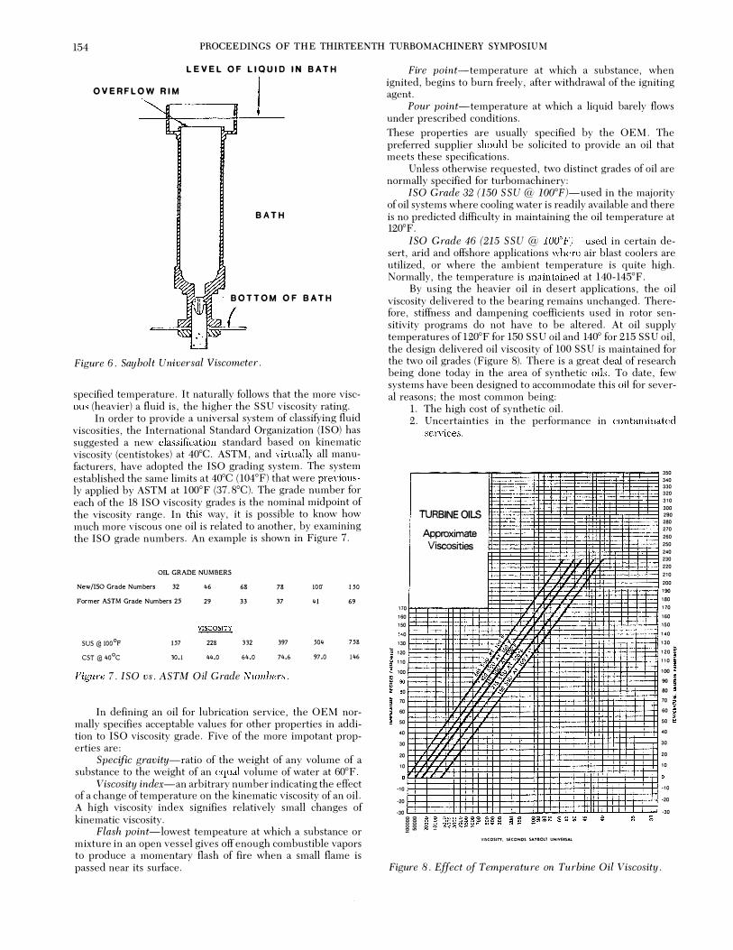
The most important property of an oil is its viscosity rating. In the United States, the Saybolt Seconds Universal (SSU) is a familiar viscosity rating. The ratings are determined with the Saybolt Universal viscometer or flow cup (Figure 6). The liquid is poured into the cup and the discharge time is measured and related to viscosity. The cup has an overflow rim to ensure the correct level and a reproducible volume, and is usually immersed in a temperature-controlled bath.
SSU viscosity is defined as the run-out time, in seconds, of 60 cubic centimeters of liquid through a standard orifice at a
154 PROCEEDINGS OF THE THIRTEENTH TURBOMACHINERY SYMPOSIUM
LEVEL OF LIQUID IN BATH
OVERFLOW RIM
j
BATH
BOTTOM OF BATH
Figure 6 . Say bolt Universal Viscometer .
specified temperature. It naturally follows that the more viscous (heavier) a fluid is, the higher the SS U viscosity rating.
In order to provide a universal system of classifying fluid viscosities, the International Standard Organization (ISO) has suggested a new classification standard based on kinematic viscosity (eentistokes) at 40°C. ASTM, and virtually all manufacturers, have adopted the ISO grading system. The system established the same limits at 40°C (104°F) that were previously applied by ASTM at 100°F (37.8°C). The grade number for each of the 18 ISO viscosity grades is the nominal midpoint of the viscosity range. In this �ay, it is possible to know how much more viscous one oil is related to another, by examining the ISO grade numbers. An example is shown in Fi)!;ure 7.
.
OIL GRADE NUMBERS New /ISO Grade Numbers 32
Former ASTM Grade Numbers 25
SUS@ 100°F CST@ 40°C
!57 10.1
46 29
� 228 44.0
68
33
332 64.0
78
37
397 74.6
Figure 7 . ISO vs . ASTM Oil Grade Numbers .
100 !50 41 69
504 758 97.0 146
In defining an oil for lubrication service, the OEM normally specifies acceptable values for other properties in addition to ISO viscosity grade. Five of the more impotant properties are:
Specific gravity-ratio of the weight of any volume of a substance to the weight of an equal volume of water at 60°F.
Viscosity index-an arbitrary number indicating the effect of a change of temperature on the kinematic viscosity of an oil. A high viscosity index signifies relatively small changes of kinematic viscosity.
Flash point-lowest tempeature at which a substance or mixture in an open vessel gives off enough combustible vapors to produce a momentary flash of fire when a small flame is passed near its surface.
Fire point-temperature at which a substance, when ignited, begins to burn freely, after withdrawal of the igniting agent.
Pour point-temperature at which a liquid barely flows under prescribed conditions.
These properties are usually specified by the OEM. The preferred supplier should be solicited to provide an oil that meets these specifications.
Unless otherwise requested, two distinct grades of oil are normally specified for turbomaehinery:
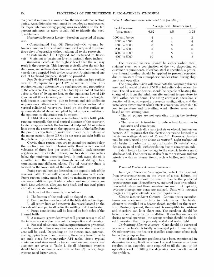
ISO Grade 32 (150 S S U@ 100°F)-used in the majority of oil systems where cooling water is readily available and there is no predicted difficulty in maintaining the oil temperature at 120°F.
ISO Grade 46 (215 S S U @ 100°F)-used in certain desert, arid and offshore applications where air blast coolers are utilized, or where the ambient temperature is quite high. Normally, the temperature is maintained at 140-145°F.
By using the heavier oil in desert applications, the oil viscosity delivered to the bearing remains unchanged. Therefore, stiffness and dampening coefflcients used in rotor sensitivity programs do not have to be altered. At oil supply temperatures of 120°F for 1.50 SSU oil and 140° for 215 SSU oil, the design delivered oil viscosity of 100 SSU is maintained for the two oil grades (Figure 8). There is a great deal of research being clone today in the area of synthetic oils. To date, few systems have been designed to accommodate this oil f<Jr several reasons; the most common being:
l. The high eost of synthetic oil. 2. Uncertainties in the performance in contaminated
services.
-·
I= ... ..
-� I.:.. - ·
r-r-· ..
TURBINE OILS I=
17 0 16 0 15 0
0 13 0 12 0 , 0 10 0
0 0
70 60 50 40 30 20 10
·10 ·20 ·30
Approximate Viscosities
1-- -- .. 1--1--
n
-
• -
::;
VI�COSITT, �ECONDS 5AY80!.T UNIVERSAl.
l= -
·I-
1-f---
..
1-
Figure 8 . Effect of Temperature on Turbine Oil Viscosity .
350 340 330 320 310 300 290 280 270 260 250 240 230 220 210 200 190 180 170 160 150 140 130 120 110 100 90 ao 70 60 50 40 30 20 10
·10 ·20 ·30

TUTORIAL SESSION ON LUBE A N D SEAL OIL SYSTEMS 155
API 614 Specifications
API 614 indicates an ISO 32 turbine oil as the lubrication fluid. ISO 32 and ISO 46 oils are commonly utilized; however, SAE 10, 20, and ISO 78 oils have been used in different applications. The important consideration is that the system should operate on the fluid it was designed for.
Potential Problem Areas-Oil
Drop in Oil Viscosity
Oil viscosity must be monitored periodically and compared to the oil design specifications. A drop in the oil viscosity could result in damage to rotor journal areas and bearings, as well as oil pump rotors. This area is especially of concern where compressors handling hydrocabron gases are utilized. Atmospheric degassing tanks will supply satisfactory results for light hydrocarbons, providing contaminated seal oil leakage rates are acceptable. However, reconditioning of the oil can only be accomplished by vacuum degassing/dehydration.
Drop in Oil Flash Point
The safety implications of this change in the oil characteristic is obvious. Again, vacuum degassing is the most effective method of treating the problem, although numerous other methods have been attempted, including nitrogen sparging.
Use of Synthetic Oil
The introduction of any lubricant, other than that for which the system was designed, can only be approved after a complete review of each of the individual components and the compatibility of the oil with them. Typical areas of concern are pump limitations, reservoir internal coatings, and elastomers used in pump seals and switches. For seal oil systems, the effect of process gas contamination on the synthetic's properties must be considered.
MAJOR COMPONENTS
Reservoir
Design Considerations
API 614 specifies the mechanical construction of the oil reservoir, its basic features, and standard and optional ancillary devices. The most relevant considerations in reservoir design are:
• adequate rundown capacity. proper materials for the jobsite conditions.
• sources of overpressure, venting, and purging. accurate specification of ambient conditions and utility availaLility for heaters.
• adequate pump suction conditions. Size and the details of construction vary markedly from
user to user for API 614. Retention times from two minutes to 15 minutes, varying by system size and application, have been used. Detail design and instrumentation have varied similarly.
API 614 Specification Requi rements
Reservoir capacities are in accordance with API 614 and are based on normal oil system flows. Normal flow is defined as the total amount of oil flow that is required at the bearings, seals, couplings, and steady state controls. Normal oil flow does not include oil which is bypassed directly back to the reservoir or transients. Based on this definition, oil reservoirs are designed in accordance with the following:
Working capac ity-the volume of oil between the minimum operating level and pump suction loss level (level at
which the oil pump loses prime-typically two to six inches above pump suction level). This capacity is sufficient for five minutes of normal oil flow.
Retention capacity-the total volume of oil below the minimum operating level. Equivalent to eight minutes of normal oil flow.
An API 614 oil reservoir capacity shematic outline is shown in Figure 9. A typical rectangular tank with the various oil levels depicted is featured in Figure 10. This tank uses stilling tubes for the oil returns.
RUNDOWN fCAPACITY __ U.S.GALLONS __ LITRE S
__ U.S. GALLONS __ LJTRES
WORKING CAPACITY -- �.S. GALLONS __ LJTRES
RETENTION C APACITY 6.ta ..
TOP OF Ql b RESERVOIR
RUN D OWN LEVEL
MAXIMUM OIL LEVEL
MINIMUM OIL LEVEL
SUCTION LOSS LEVEL
--- U.S. GALLONS PUMP SUCTION LEVEL ___ LJTRES
I INSIDE BOTTOM L---.�==========c=�==========�O�F�RE�S�E�R�V�O�IR
CHARGE CAPACITY (OIL ReOUIRED FOR INITIAL SYSTCM FILL)
__ U.S . GALLO N S __ LITRES
SCHEMATIC O IL R E SE RVOIR C A P A CITIES
Figure 9 . Oil Reservoir Capacity .
SUPPORT. IF REOUIREO.
1M MERSON HEATER
Figure 1 0 . Rectangular Reservoir .
In addition to the working capacity and the retention capacity, several other terms must be defined:
Rundown Capacity-includes oil contained in all components, bearing and seal housings, control elements, and vendor furnished piping that drain back to reservoir. Also included is a
156 PROCEEDINGS OF THE THIRTEENTH TURBOMACHINERY SYMPOSIUM
ten percent minimum allowance for the users interconnecting piping. An additional amount must be included as an allowance for major interconnecting piping runs in addition to the ten percent minimum as users usually fail to identify the need quantitatively.
Maximum/Minimum Levels-based on expected oil usage rate.
• Contaminated Seal Oil Discarded-Oil volume between minimum level and maximum level required to sustain three days of operation without adding oil to the reservoir.
• Contaminated Oil Degassed and Returned to Reservoir-Minimum to maximum level is typically three inches.
Rundown Level�is the highest level that the oil may reach in the reservoir. This happens typically after the unit has shutdown, and oil from drain lines and overhead oil-containing vessels have emptied back to the reservoir. A minimum of one inch of freeboard (airspace) should be provided.
Free ·suiface-API 614 requires a minimum free surface area of 0. 25 square foot per GPM of normal oil flow. This requirement may determine the configuration and proportions of the reservoir. For example, a ten foot by six foot oil tank has a free surface of 60 square feet, or the equivalent flow of 240 gpm. As oil flows increase, and thus tank size, a rectangular tank becomes unattractive, due to bottom and side stiffening requirements. Attention is then given to either horizontal or vertical cylindrical reservoirs. Based on the free surface requirements stated above, and plant layout or space limitations, the optimum configuration can be chosen.
API 614 oil reservoirs are manufactured with a baffle plate running practically the total vertical distance of the reservoir, located at approximately the horizontal midpoint. All oil return lines enter the reservoir on the opposite side of the baffle from the pump suction lines to avoid disturbance or turbulence at the pump suction. Some O EMs do not use a gas tight baffle as they believe it provides no advantage.
Gravity drain return lines are to extend two inches below the suction loss level. Drains with flows which exceed velocities of three feet per second (typically back pressure regulator and relief valve returns) are to extend four inches below the minimum operating level. In both cases, the oil is admitted into the reservoir through vented stilling tubes, terminating into diffusion plates. The oil reservoir drain is located on the lower side of the internal baffle.
Pump suction lines are located on the opposite side of the reservoir baffle. There will be no additional drains on this side. Pump suction piping must be sized to maintain proper pump suction conditions, particularly when suction strainers are used. Low velocities, adequate tank head, and anti-swirl plates virtually eliminate vortexing.
The layout of the reservoir is as follows:
l. The bottom of the tank will be sloped 1/4 in/ft. 2. Pump suctions are located at the high side of the slope. 3. All return lines and reservoir drains are located on the
low side of the slope, to allow for the settling of dirt and water. 4. Purge connections will be located on both sides of the
internal baffle. 5. A manway is provided which will permit access to all of
the internal areas of the reservoir for inspection and cleaning. 6. For seal oil systems, tank overpressurization protection
must be provided. For many situations, an oversized reservoir vent will be used. Depending on the system size, interconnecting piping layout, and pressure, these vary from three to ten inch sizes for rectangular API tanks. Some typical minimum vent sizes used on tanks based on compressor seal diameter are given in Table l. Small lubrication systems should have a minimum vent size of two (2) inches, large systems need larger vents.
Table 1 . Minimum Reservoir Vent Size (in . dia . ) .
Seal Pressure Average Seal Diameter (in. )
(psig, -max. ) 6. 62 4. 5 3. 75
1000 and below 4 4 3 1000 to 1500 6 4 4 1500 to 2000 6 6 6 2000 to 3000 8 6 6 3000 to 4000 8 8 6 4000 to 5000 10 8 8
The reservoir material should be either carbon steel, stainless steel, or a combination of the two depending on customer requirements. If carbon steel is specified, a protective internal coating should be applied to prevent corrosion due to moisture from atmospheric condensation during shipment and operation.
The pump discussion will make note that oil pump drivers are sized for a cold oil start of 50°F at full relief valve accumulation. The oil resevoir heaters should be capable of heating the charge of oil from the minimum site ambient temperature to 70°F within twelve hours. The sizing criteria is, therefore, a function of time, oil capacity, reservoir configuration, and the installation environment which affects convection losses due to low temperature and prevailing wind. Heater selection is based on two assumptions:
• The oil pumps are not operating during the heat-up time.
• The reservoir is insulated to reduce heat losses due to radiation and convection.
Heaters are typically steam jackets or electric immersion heaters. API requires that the electric heaters be limited to a maximum wattage density of 15 watt/in2. However, heaters may be safely used up to about 22 watt/in2• Light turbine oil will begin to carbonize at approximately 25 watt/in2 watt density in an oil tank, with circulation due to convection only.
Safety factors for low voltage to the electric heaters must also be added. The heater must also fit in the reservoir and not interfere with any internal items, such as baffles, return lines, etc.
Potential Problem Areas-Reservoirs
Improper Reversoir Venting-To protect the reservoir from overpressurization in the event of a seal failure, the reservoir vent area should be sized to handle the predicted pressurization rate. Blowoff covers, ruptured discs or combination relief valves and flame arrestors are used, but typically, oversize atmospheric vents are utilized. Units with nitrogen purging are typical offenders of this requirement.
Electric Heater S hort Circuits-Certain heater manufacturers use a ceramic insulator in their heater. The heater element is installed in a heater sheath supplied in the reservoir. During shipment, the ceramic is susceptible to moisture and therefore can later short out. The insulator should be baked in an oven prior to installation. If shorting out occurs during normal operation, the wiring conduit should be checked to ascertain that it is properly sealed and water tight.
Carbonizing Electric Heaters-Care should be exercised to assure the heater is totally submerged prior to energizing. On oil reservoirs, the heater is installed a minimum of one inch below the pump section.
Most of these heater problems have been experienced in degassing tank applications where low seal leakage rates have resulted in an extended time required to fill the tank to the operating level. Prefilling the degassing tank has eliminated the problem.
TUTORIAL SESSION ON LUBE AND SEAL OIL SYSTEMS 151
Damaging of Reservoir Internal Coating-Care should be exercised during the flush, inspection, and manual internal cleaning of carbon steel reservoirs with internal coating. Boots must be removed during internal inspection. Additionally, welding on the reservoir perimeter severely damages the coating.
Addition of Overhead Rundown Tanks-After the reservoir is installed, an overhead rundown tank may be instailed to improve system reliability during power failures. The rundoWn capacity must be reviewed. As an example, during commissioning of a unit, the oil reservoir was filled to the normal operating level. As the new overhead tank filled, the oil level in the reservoir dropped. More oil was added to return the oil to the normal level and the system was commissioned. Two years later, on a power failure, the oil overflowed the reservoir and flooded the area.
For rotating equipment with a reservoir installed in the baseplate, the reservoir operating temperature must be considered when calculating thermal growth figures for shaft alignment.
Oil contamination-Check that the vents are not tied to the flare system which can pressurize during upset conditions and dump condensate into the reservoir.
Pumps
Design Considerations
A good pump selection is the heart of an effective and efficient oil system. If the pump is of the proper flow capacity, pressure capability, and operating range, there are seldom pump related system problems.
For positive displacement pumps, the effects of relief valve accumulation, low viscosity, and reduced suction conditions must be considered. The flow margin should consider controllability at design and off design conditions and available frame sizes, more than fixed percentages.
For centrifugal pumps, the more important design parameters are head variations, startup viscosity, net positive suction head (NPSH) submergence requirements, and pressure and head limitations.
API 614 Specification Requirements
The oil pump is the heart of an oil system. In general, the most widely used pump is the positive displacement screwtype. There are several reasons for this choice:
• Reliability • Quiet, vibration-free performance • Absence of pulsations • Wide rangeability • Efficiency • High pressure capability Gear, vane and piston positive displacement pumps are
also used on occasion in unique circumstances. Single-stage centrifugal pumps are the second most com
mon type of pump used. Typically, they are utilized for moderate to large flows at lower pressure, either alone or as the primary pumps in a four pump (booster) system.
API 610 horizontal, vertical turbine, and in line centrifugal pumps are used on occasion. Multistage API pumps for higher heads are not economically practical.
Drivers shall be sized, according to API, as follows: Positive Displacement-Horsepower rating should be suf
ficient to operate the pump at relief valve full accumulation pressure and 50°F oil temperature.
Centrifugal-Horsepower rating should be sufficient to operate the pump at the design system pressure with 50°F oil temperature.
The sizing of oil pumps cannot be done casually. Several important factors must be considered before the proper selection can be made. To determine flow capabilities, one must first know the system oil flow requirements to each machine and its auxiliaries. This must include the maximum transient control oil flow, parasitic relief valve leakage, if applicable, and other oil consutnptions.
The oil system configuration Is determined in a large part by the oil pumps and their control method. Positive displacement pump selection by API 614 criteria is to be 115 percent of the maximum system usage ( 120 percent or 10 gpm for seal systems). This is reasonably conservative and provides an adequate control margin. Significant oversizing of pumps should be avoided for reasons of cost and poor driver efficiency. Depending again on size, selections from 105 percent to 200 percent of the maximum capacity have been used.
Centrifugal pump selection must consider the necessary head throughout the console operating range. Care to avoid excessive head is important. Improper application of general user pump specifications can be problematical, resulting in poor system efficiency and higher costs.
The pump discharge pressure must be set by determining the maximum required delivery pressure and the system losses. The highest ultimate pressure required at the machinery system must be determined. In many cases, this is the seal oil pressure required at compressor shutdown, and process settling pressure prior to venting. Failure to specify the correct settling pressure or maximum shutdown pressure is a major coordination problem.
Static Head-The difference in elevation between the console and the machinery that it services.
Interconnecting Piping Losses-Unless exact data is available, experience has proven that 10 psig is a conservative figure.
Pressure Reducing Valves-The pressure drop needed in order to maintain satisfactory control and control valve size; typically, 20 psid is appropriate. In applications where the back pressure regulator maintains the highest delivered oil pressure, this factor is not necessary. This type of system is known as a differential back pressure regulating system.
Console Piping Losses-Factory evaluation has shown 5 psi to be satisfactory.
Transfer Valve Loss-Maximum design pressure drop, typically about 5 psi.
Cooler Loss-Maximum design pressure drop, typically about 10 psi.
Filter Loss-For pump sizing purposes, a maximum dirty filter pressure drop of 20 psi is used, although this value can be exceeded in operation.
These factors will be covered in more detail under their respective headings. Adding all of these factors together results in the total required pump discharge pressure:
( ) Maximum Required Pressure ( ) Static Head (10) Interconnecting Piping Loss (20) Pressure Reducing Valve ( 5) Console Piping Losses ( 5) Transfer Valve Loss (10) Cooler Loss (20) Filter Loss Total= Required Pump Discharge Pressure. Due to the design characteristics of the screw-type pump,
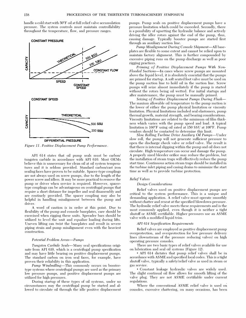
the flowrate increases as the oil viscosity increases as shown in Figure 1 1. Therefore, the pump must be capable of delivering the required design performance at an oil viscosity of 65 SSU (based on light turbine oil, ISO Grade 32, and an approximate oil reservoir temperature of 150°F). Also, the pump must
158 PROCEEDINGS OF THE THIRTEENTH TURBOMACHINERY SYMPOSIUM
handle a cold start with 50°F oil at full relief valve accumulation pressure. The system controls must maintain controllability throughout the temperature, flow, and pressure ranges.
CONSTANT PRESSURE
CONSTANT FLOW "i------
SPEED
CONSTANT SPEED
1 I
CONSTANT SPEED
THEORETICAL � �r---"""'=:::::::::::==::::::=----� soossu
200SSU
DIFFERENTIAL PRESSURE Figure 1 1 . Positive Displacement Pump Performance .
API 614 states that oil pump seals must be carbon/ tungsten carbide in accordance with API 610. Most OEMs believe this is unnecessary for clean oil at oil system temperatures and it is seldom provided. Standard carbon/cast iron seailng faces have proven to be suitable. Spacer-type couplings are not always used on screw pumps, due to the length of the power screw and idlers. It may be more practical to remove the pump or driver when service is required. However, spacertype couplings can be advantageous on centrifugal pumps that require a short distance for impeller and seal disassembly and are routinely provided. The spacer coupling may also be helpful in handling misalignment between the pump and driver.
A word of caution is in order at this point. Due to flexibility of the pump and console baseplates, care should be exercised when rigging these units. Spreader bars should be utilized to level the unit and equalize loading during lifts. Uneven lifting can twist the baseplates and result in severe piping strain and pump misalignment even with the heaviest construction.
Potential Problem Areas-Pumps
Tungsten Carbide Seals-Many seal specifications originate from API 610, which is a centrifugal pump specification and may have little bearing on positive displacement pumps. The standard carbon on iron seal faces, for example, have proven their reliability in this application.
Pump Windmilling-This commonly occurs on boostertype systems where centrifugal pumps are used as the primary low pressure pumps, and positive displacement pumps are utilized for high pressures.
During startup of these types of oil systems, under no circumstances may the centrifugal pump be started and allowed to circulate oil through the idle positive displacement
pumps. Pump seals on positive displacement pumps have a pressure limitation which could be exceeded. Secondly, there is a possibility of upsetting the hydraulic balance and actively driving the idler rotors against the end of the pump, thus, causing damage. Typically booster pumps are started first through an auxiliary suction line.
Pump Misalignment During Console S hipment-All baseplates are flexible to some extent and cannot be relied upon to maintain factory alignment. This is further compounded by excessive piping runs on the pump discharge as well as poor rigging practices.
Priming of Positive Displacement Pumps With NonFlooded Suctions-In cases where screw pumps are mounted above the liquid level, it is absolutely essential that the pumps are primed for startup. A soft seated foot valve must be used on the pump suction line to hold oil in the suction line. Screw pumps will seize almost immediately if the pump is started without the rotors being oil wetted. For initial startups and after maintenance, the pump must be manually primed.
Seizing of Positive Displacement Pumps During FlushThe maxium allowable oil temperature to the pump suction is the lower of either the pump physical limitation or viscosity limitation. Physical limitations included seal elastomers, pump thermal growth, material strength, and bearing considerations. Viscosity limitations are related to the minimum oil film thickness which varies with the pump speed and load. A typical limitation is l60°F using oil rated at 150 SSU at 100°F. Pump vendors should be contacted to determine this limit.
Slow Rolling Turbine Drive Auxilary Oil Pumps-Under slow roll, the pump will not generate sufficient pressure to open the discharge check valve or relief valve. The result is that there is internal slipping within the pump and oil does not circulate. High temperature can occur and damage the pump. A properly sized bleeder orifice may reduce the problem, but the installation of steam traps will effectively reduce the pump start time. Continuous action steam traps should be installed in the turbine inlet piping and casing drains to minimize the start time as well as to provide turbine protection.
Relief Valves Design Considerations
Relief valves used on positive displacement pumps are critical to the system performance. This is a unique and demanding application. A relief valve must operate smoothly without chatter and reseat at the specified blowdown pressure. The hydraulic relief valve meets these requirements and is the most commonly applied, even though it is neither a tight shutoff or ASME certifiable. Higher pressures use an ASME valve with a modified liquid trim.
API 614 Sepcification Requirements
Relief valves are employed as positive displacement pump overprotection, and overprotection for low pressure delivery lines (downstream of the pressure reducing valves) on high operating pressure consoles.
There are two basic types of relief valves available for use on lubrication and seal oil systems (Figure 12).
• API 614 dictates that pump relief valves shall be in accordance with ASME and specified local codes. This is a tight shutoff valve, typically a safety/relief valve as used in steam or gas service.
• Constant leakage hydraulic valves are widely used. The slight continual oil flow allows for smooth lifting of the valve plug. They are not ASME certifiable under current regulations.
Where the conventional ASME relief valve is used on consoles, excessive chattering, on many occasions, has been

TUTORIAL SESSION ON LUBE AND SEAL OIL SYSTEMS 159
experienced during plug lifting, and seat damage has occurred. A great deal of effort has been expended to solve this problem and demonstrably successful designs are available. However, in oil systems with relatively low pressure levels, the hydraulic type relief valve becomes more attractive. Although the seat leakage must be designed for, the plug lift is smooth, and instability during lifting is eliminated. Oil system manufacturers have taken exception to API 614 and utilize these relief valves in view of their smooth performance. These valves can be set only by their accumulation pressures or by careful observation.
PROCESS RELIEF VALVE HYDRAULIC RELIEF VALVE
Figure 12 . Process vs . Hydraulic Relief Valves .
At this point, it is beneficial to define several terms. Pump Discharge Pressure (P d)-As discussed under
"Pumps." The highest pressure required at the pump discharge, based on maximum oil demands at the unit.
Set Pressure (P Set)-typically 1 10 percent of the pump discharge pressure. This is the pressure at which the relief valve plug begins to lift.
Overpressure (P over )-10 to 25 percent of the set pressure. The pressure rise above the set pressure realized when the relief valve is passing full pump flow.
Full Flow Pressure (P Fullflow)-Set pressure plus overpressure. The pressure at which hydraulic valves can be accurately set.
An example may aid in clarifying these terms. Assume that a required pump discharge pressure has been calculated to be 480 psig.
P d = 480 psig P set = P d X 1. 1
= 480 X 1.1 = 528 psig P over = P set X 0.1
= 528X0. 1= 53 psig
Unless relief valve performance characteristics are known, it is best to choose 10 percent overpressure therefore,
P full flow = P set + P over = 528+53 = 581 psig
Due to the constant leakage characteristics of hydraulic relief valves at their set pressure (0. 1 to 0. 5 gpm for direct acting valves, as high as eight to twelve gpm for larger pilot actuated valves, setting these valves with steam or gas medium is impractical, and visual set pressure determination is difficult. It is, therefore, · best to adjust the hydraulic relief valve in place on the console. This can be accomplished by closing the pump discharge isolation valve, and using full flow pressure as the setting criteria. This can be monitored using the pump discharge pressure gauge. In the example, with the full
flow of the pump passing through the relief valve, the pressure gauge should register 581 psig.
Setting of oil system ASME relief valves can be handled in the routine manner. In other words, the valves can be accurately set using steam or gas on a bench. The set pressure can be accurately adjusted.
ASME relief valves must be mounted vertically. However, hydraulic relief valves can be oriented in any position.
The addition of a relief valve bypass valve (usually a globe valve) is very desirable. These bypasses make pump transfers safer, easier, and more reliable. To accomplish a transfer, the bypass of the idle pump is first opened, and then the pump is started, thus diverting full pump flow back to the reservoir (Figure 13). The relief valve bypass is slowly closed until both pumps are supplying oil into the system, with excess being dumped through the back pressure regulator to the reservoir. The bypass of the pump that was originally in operation can now be slowly opened, until all the pump flow is being diverted back to the reservoir, and the back pressure regulating valve (BPRV) is allowed to respond. The pump can now be confidently stopped with no oil system upsets or trips.
Figure 1 3 . Relief Valve Bypass.
Relief valve bypasses also aid in auxiliary oil pump start switch testing, and horsepower reduction on cold oil starts. Basically, the bypass provides a means of manually manipulating the pumps for maintenance or testing.
Potential Problem Areas-Relief Valves
Chattering of relief valves at set pressure-Recent work with vendors has all but eliminated this problem. Valve designs were modified in the areas of surface finish on sliding faces, diametral clearances, materials of construction, and spring rate to set pressure rates.
Excessive relief valve leakage below relief valve set or lift off pressure-Improper field setting of relief valves has caused numerous field problems. Improper setting has been determined as the root cause of the following problems:
• Inability of the main oil pump to maintain system pressure.
• Inability to switch pump duty without tripping the string on low seal oil to gas differential pressure or low lube oil pressure.
• Observance of the backpressure regulating valve operating fully closed.
• Observance of the bearing oil regulating valve operating fully open. This applies to systems with relief valves installed downstream of the bearing oil regulators which are used as bearing housing overpressurization protection.
Areas to check if these problems are present: • Check that relief valves were properly set. For hydraulic
relief valves, field setting should incorporate the full accumulation method.
• Check relief valve for foreign material.
160 PROCEEDINGS OF THE THIRTEENTH TURBOMACHINERY SYMPOSIUM
Relief valve sticking or squealing at set pressure-On recent installations, the relief valves on auxiliary oil pumps have been found mounted above the reservoir oil level. The absence of oil on the idler pump leads to corrosion of the relief valve. Additionally, when the auxiliary pump is started, the pressurization of the air in the discharge causes the relief valve to squeal. A recommendation is to drill a small hole in the discharge check valve (typically V16 in), or add an adjustable bleeder valve to flood the pump discharge. If the flow is too excessive, the pump could rotate backwards.
Oil Coolers
Design Considerations
The most important concern in an oil cooler is ad�quate surface area to reject all the system losses. This is very often overlooked in high pressure systems. When experience indicates fouling is not a maintenance problem, many users will use a single cooler.
API 614 Specification Requirements
Oil coolers must be designed to remove the total heat added from every source. This includes heat contributed by all bearings, seals, gears, and pumps.
API 614 specifies that shell�and-tube type coolers used for oil systems be code constructed, built in accordance with Tubular Exchanger Manufacturers Association (TEMA) C; have removable bundles, steel shells, channels and covers, tube sheets of naval brass and tubes of inhibited admirality. However, these specifications can be changed to suit the needs and preference of the user. Fixed bundles, u-tubes, different tube pitches, and TEMA R have all been used.
The cooler should have vent and drain connections on both the oil and water sides. Oil flows should oppose water inlet flows, if system layouts permit. Temperature control bypass piping may be installed if desired. However, it is important to note that temperature control valves should fail in such a position as to divert the total oil flow through the coolers.
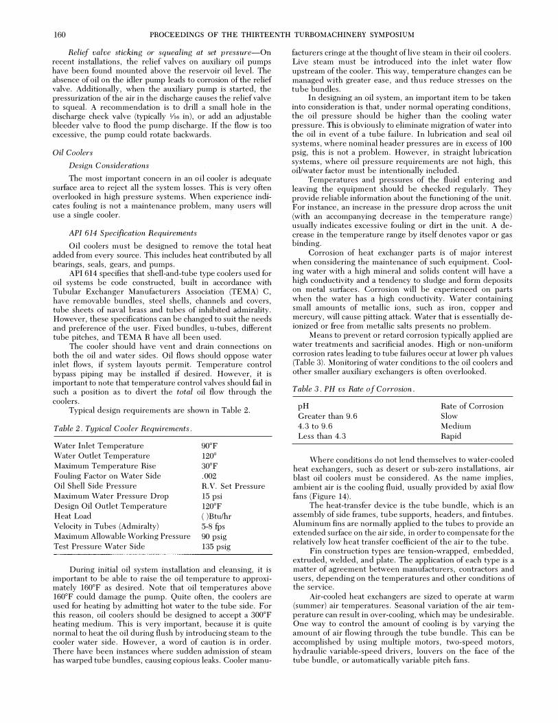
Typical design requirements are shown in Table 2.
Table 2 . Typical C ooler Requirements .
\Vater Inlet Temperature Water Outlet Temperature Maximum Temperature Rise Fouling Factor on Water Side Oil Shell Side Pressure Maximum Water Pressure Drop Design Oil Outlet Temperature Heat Load Velocity in Tubes (Admiralty) Maximum Allowable Working Pressure Test Pressure Water Side
90°F 120° 30°F .002 R. V. Set Pressure 15 psi 120°F ( )Btulhr 5-8 fps 90 psig 135 psig
During initial oil system installation and cleansing, it is important to be able to raise the oil temperature to approximately 160°F as desired. Note that oil temperatures above 160°F could damage the pump. Quite often, the coolers are used for heating by admitting hot water to the tube side. For this reason, oil coolers should be designed to accept a 300°F heating medium. This is very important, because it is quite normal to heat the oil during flush by introducing steam to the cooler water side. However, a word of caution is in order. There have been instances where sudden admission of steam has warped tube bundles, causing copious leaks. Cooler manu-
facturers cringe at the thought of live steam in their oil coolers. Live steam must be introduced into the inlet water flow upstream of the cooler. This way, temperature changes can be managed with greater ease, and thus reduce stresses on the tube bundles.
In designing an oil system, an important item to be taken into consideration is that, under normal operating conditions, the oil pressure should be higher than the cooling· water pressure. This is obviously to eliminate migration of water into the oil in event of a tube failure. In lubrication and seal oil systems, where nominal header pressures are in. excess of 100 psig, this is not a problem. However, in straight lubrication systems, where oil pressure requirements are not high, this oiVwater factor must be intentionally included.
Temperatures and pressures of the fluid entering and leaving the equipment should be checked regularly. They provide reliable information about the functioning of the unit. For instance, an increase in the pressure drop across the unit (with an accompanying decrease in the temperature range) usually indicates excessive fouling or dirt iri the unit. A decrease In the temperature range by itself denotes vapor or gas binding.
Corrosion of heat exchanger parts is of major interest when consideting the maintenance of such equipment. Cooling water with a high mineral and solids content will have a high conductivity arid a tendency to sludge and form deposits on metal surfaces. Corrosion will be experienced on parts when the water has a high conductivity. Water containing small amounts of metallic ions, such as iron, copper and mercury, will cause pitting attack. Water that is essentially deionized or free from metallic salts presents no problem.
Means to prevent or retard corrosion typically applied are water treatments and sacrificial anodes. High or non-uniform corrosion rates leading to tube failures occur at lower ph values (Table 3). Monitoring of water conditions to the oil coolers and other smaller auxiliary exchangers is often overlooked.
Table 3 . PH vs Rate of Corrosion .
pH Greater than 9.6 4.3 to 9.6 Less than 4.3
Rate of Corrosion Slow Medium Rapid
Where conditions do not lend themselves to water-cooled heat exchangers, such as desert or sub-zero installations, air blast oil coolers must be considered. As the name implies, ambient air is the cooling fluid, usually provided by axial flow fans (Figure 14).
The heat-transfer device is the tube bundle, which is an assembly of side frames, tube supports, headers, and fin tubes. Aluminum fins are normally applied to the tubes to provide an extended surface on the air side, in order to compensate for the relatively low heat transfer coefficient of the air to the tube.
Fin construction types are tension-wrapped, embedded, extruded, welded, and plate. The application of each type is a matter of agreement between manufacturers, contractors and users, depending on the temperatures and other conditions of the service.
Air-cooled heat exchangers are sized to operate at warm (summer) air temperatures. Seasonal variation of the air temperature can result in over-cooling, which may be undesirable. One way to control the amount of cooling is by varying the amount of air flowing through the tube bundle. This can be accomplished by using multiple motors, two-speed motors, hydraulic variable-speed drivers, louvers on the face of the tube bundle, or automatically variable pitch fans.

TUTORIAL SESSION ON LUBE AND SEAL OIL SYSTEMS 161
H E A D E R S
w a: ::> ... () ::> a: ... .. " z ;:: a: 0 .. .. ::> .,
T U B E B U N D L E S
A I R P L E N U I.l C H A I.I B E R
F A N t.:: /
D R I V E A S S E M B L Y
F O R C E D D R A FT
Figure 14 . Typical Air Blast Cooler .
D R I V E R
Staging of fans or fan speeds may be adequate for systems which do not require precise control of the process temperature or pressure. Louvers will provide a full range of air quantity control. They may be operated manually, or automatically operated by a pneumatic or electric motor controlled by a remote temperature or pressure sensor on the process stream.
In an effort to reduce the cooler size, and therefore cooling water flow, the back pressure regulating valve is usually located upstream of the coolers, as shown in Figure 15 .
BPR
RESERVO I R
I N LET T � 1 50 ' F
Figure 1 5 . Heat Schematic .
ll T = � BTU I H A INPUT JO'F (202.41 (GPMI <
\ D E S I G N 1 20 ' F ALL H EAT OUT
To facilitate maintenance while in operation, coolers are usually mounted in parallel, with interchangeability being accomplished by the use of a transfer valve.
Potential Problem Area-Oil Coolers
Oil heating for flush-Past practice of introducing steam directly into the water side tube bundles to heat the oil is not recommended, unless the cooler was specifically designed for this service. Such practice causes differential expansion strains, with possible leakage at the tube joints.
Cooler thermal cycling-Another practice used to reduce the system flush time is to thermally cycle the oil. Most cooler manufacturers recommend the cooler not be thermally cycled
more than two or three times a day. M anufacturers should be consulted if this procedure is used to flush the system.
Drop in cooler efficiency after cleaning-Certain coolers, especially smaller units, are designed so that the number of water passes can be varied depending on the bonnet head position. After maintenance, check for the proper position of the bonnet to ensure adequate heat transfer.
Excessive tube failures-Two main causes of tube failure are fatigue and erosion. Both can be controlled by maintaining the design water flow. Excessive water flow can cause flowinduced vibration which, if the tube natural frequency is excited, could lead to fatigue failure. E xcessive water flow also accelerates tube erosion. A recommendation is to monitor the water flow.
Oil Filters
Design Considerations
Oil filters consist of two distinct parts: the housing and the filter cartridges. Housings should be provided with valved vents and drains, a pressure equalization line, and coverlifts for larger vessels. Off the shelf non-code housings may be used for low pressure systems if user and jobsite requirements permit. Filter bypasses should be prohibited. Filter elements should be replaceable disposable elements, be sized to give a reasonable service life without excessive pressure drop, and changed no less often than every 6 months of service.
API 614 Specification Requirements
Oil filters should be the last component that the oil contacts (except for the pressure reducing valves) before servicing the intended machinery. For this reason, typical console arrangement provides cooling first, then filtration. This arrangement also allows the removal of any debris from the oil that may have been trapped in the cooler tube bundle.
All API-specified oil systems have twin oil filters. Typically, a filter is piped in series with a cooler, and interconnection with the alternate set is provided by a transfer valve, as was shown in Figure 5. However, filter sets and cooler sets have been independently arranged, depending on user preference.
For bearing design purposes, a minimum oil film thickness of 0. 00075 in (% mil) is typical. Therefore, a filter element capable of removing large particles is required. The API 614 requirement is 1 0 microns (0. 00039 in) nominal filtration.
Probably the most widely used filter element is the cotton cartridge with a cotton wound matrix and metal core. This type of element provides excellent filtration and can handle small amounts of water. Collapse pressure ratings are usually 90 psid.
A second type of filter that is commercially available is the acrylic fiber element with resin binders. These elements are basically impervious to water . However, they have been known to fracture and break during cold oil starts. Therefore, added caution is necessary when this type filter media is utilized. The acrylic cartridge provides excellent service where steam turbine drivers are employed, due to its water-resistant qualities (it will not swell). Fiberglass and polypropylene fiber wound elements are occasionally used as well.
Wool should not be used. It has been found in the past that oil flow through wool elements causes a build up of static electricity. In hazardous environments, this charge has resulted in explosions. Wool is, therefore, unacceptable as a filtering agent.
In the past, pleated paper elements were not recommended due to their low water tolerance level. Even the smallest amounts of water caused extreme swelling, thus re-
162 PROCEEDINGS OF THE THIRTEENTH TURBOMACHINERY SYMPOSIUM
stricting the oil flow, and resulting in high differential pressures to the point of element collapse. The modern resinimpregnated pleated paper cartridge has greatly improved the water handling capabilities of pleated paper cartridges, leading to increasing application in lurication and seal oil systems. One of the attractive features of the paper pleated cartridge is its high collapse rating, typically 100 psid. However, it must be emphasized that only resin-impregnated paper filter elements from reputable sources should be considered in oil systems.
All elements have an efficiency rating, which may range from 60 to 100 percent. This rating is readily available from the specific filter vendor. What this number indicates is the percentage of the cartridge rated particulate that will be retained by the cartridge (i.e., not allowed to pass through). As an example, a ten micron filter element with an 85 percent efficiency will hold 85 percent of all ten micron particulate, or larger. The remaining 15 percent, theoretically, finds its way through the filter and out to the machinery. However, this rating should not be used as an absolute indicator. In recirculating oil systems, larger particles are eliminated in a few passes. Experience is the true indicator of performance, and excellent life is routine with 10, 20, 40, and even 90 micron nominal filtration.
The clean oil pressure drop across a filter is a function of the flow and the oil viscosity. API 614 states that the differential pressure across the filter at 100°F shall not exceed five psi. This reading is across the filter housing and its elements only. Pressure losses due to piping, coolers, or transfer valves should not be included.
Once a filter selection has been made, it is advised that the sizing be verified to check the unit's ability to pass the maximum oil flow at 650 SSU viscosity without reaching the cartridge collapse differential pressure. This is considered the cold startup condition.
Maximum dirty pressure drop varies. However, a general rule of thumb is that elements should be changed when the differential pressure rises 15 psi above the actual clean cartridge pressure.
Typically, filter flow is from the outside of the element to the inside. There have been instances where piping configurations or transfer valves orientation has resulted in a flow reversal, causing element rupture, system contamination, and confusing differential pressure indicator readings.
Construction of the filter housing, as with oil coolers, should be ASME code constructed and/or national board inspected per jurisdictional requirements. The maximum design pressure should be in accordance with the relief valve set ·
pressure, or centrifugal oil pump shutoff head.
Potential Problem Areas-Oil Filters
High filter pressure differential-API dictates the clean filter pressure drop to be 5 psi at 100°F and normal flow.
The first area to inspect is the sensing points of the differential pressure indicator. A typical installation includes the cooler and transfer valve in the sensing system. For this arrangement, the clean filter pressure drop would be 20 psid.
Cooler 10 psid Transfer Valve 5 psid Filter 5 psid The next area that affects the filter differential pressure is
the oil viscosity. The higher the viscosity, the higher the clean filter differential. Oil viscosity is directly affected, first by the actual installed lubricant, and secondly by the oil operating temperature. As presented, the design of the cartridge requires that it not reach the predicted collapse pressure during a cold start.
The final area that directly affects filter pressure differential is the cartridge flowrate. Typically during flush, orifices are removed to enhance flow. Any increase in flow directly affects the filter differential.
Cartridge separation or unwinding-The flow through the filter housing should be in the direction that would collapse the cartridge. Certain transfer valves are designed so they can be installed backwards. The oil flow direction through the housing should be checked.
Cartridge Life-Due to the effects of flow erosion, filter cartridge vendors are predicting a cartridge efficiency life of six months.
Cartridge Ratings- Due to the absence of test requirements, 10 micron filter efficiency can vary between various cartridge suppliers. This has led to high filter differential pressure problems, especially when OEM supplied elements are replaced with another supplier's elements.
Cartridge Swelling-This has occurred on both cotton and untreated paper elements in the presence of water in the oil. This is more likely to occur on steam turbine applications due to improper operation of the gland condensers. Maintaining water content below 200 ppm has reduced the high differential pressure problem. Cartridges made of acrylic fiber with phenolic resin binders usually eliminate the problem. Resin treated paper elements also have proved successful.
Transfer Valve
Design Considerations
There are several versions of six ported continuous flow (transfer) valves. The cast taper plug valve is the most commonly applied, although several fabricated versions are available. the transfer valve is not a tight shutoff device; however, valves are available with very tolerable leakage rates.
Mechanically, transfer valves must be designed to preclude incorrect assembly, with a lifting mechanism (for taper plugs), and to be easily operable with one side depressurized.
With some OEMs, current practice is to use taper plug valves for low and moderate pressures, but a fabricated straight plug valve at higher pressures (over American National Standards Institute (ANSI) 600).
A combination of a three-way valve, two check valves and two mechanically linked three-way valves have been used in lieu of 6 ported valves upon occasion.
The use of four manual block valves in lieu of a transfer valve should not be considered.
API 614 Specification Requirements
In order to allow service of a twin filter or cooler while in operation, an easy, reliable method of transfer is required. This is accomplished by the use of a full port transfer valve. API requires that these units have cast steel bodies and stainless steel tapered valve plug.
The transfer valve sizing criteria is based on the maximum expected flow that the valve will experience . .'fhe nominal design pressure drop should be five psi. However, smaller valves may have a lower differential pressure, whereas larger valves (two in diameter and greater) may have a slightly higher pressure drop. As long as the console design takes the transfer valve pressure drop into account, no problem is anticipated.
Due to the design, transfer valves will experience higher pressure drop with the valve plug located at the mid-position of the total travel. A typical curve is illustrated in Figure 16. This drop must be taken into account during selection, because any pressure drop at the transfer valve will result in a corresponding pressure drop at the controlled header. If the transfer valve is operated too quickly, the back pressure regulator may not

TUTORIAL SESSION ON LUBE A N D SEAL OIL SYSTEMS 163
have sufficient time to respond to the sudden pressure change . This can cause the auxiliary oil pump to start, or result in a unit trip . This situation must be accurately appraised before a final selection is made .
in ..
a: 0 a: 0
1 0 1 0 0 200 .:30!1 FLOW, GPM
Figure 16 . Typical Transfe1· Valve Pressure Drop vs . Flow .
In order to further aid in transfl�r. sonte manufacturers have incorporated a lifting jack assembly, which is used to physically raise and lower the tapered plug in its scat. "\. typical assembly is illustrated in Figure 17 . In making a transfer, the plug is raised just enough to disengage it fi·om the seat, the swing is made, and the device is once again used to reseat the
Figure 1 7 . Transfer Value Lifting ] ack .
valve plug. However, tight shutoff is virtually impossible to achieve with a tapered plug transfer valve; some minor l eakage will occur from the active to the inactive side . It is for this reason that the filter and/or shells have an atmospheric drain sized accordingly .
Appropriate precautions must be taken in order to achieve an uneventful transfer . First, an orificed equalization line should be added between the twin bodies to remove entrapped air, and equalize pressures on both sides of the transfer valve prior to actuation (Figure 18). This also minimizes plug scoring by eliminating uneven loadings.
ATMOSPHERIC DRAIN VALVE ------
TRANSFER VALVE
Figure 1 8 . Recmnmended Transfer Valve Installation .
A safe transtCr sequence is as fdlows: .l. Open vents in idle cooler and filter housing. 2. Open orihced transfer valve bypass line to equalize the
pressures. 3. Upon observation of a steady stream of oil , close the
vents. 4. Turn the lifting jack the appropriate amount necessary
to lift the transfer valve pl ug. .5. Slowly move the valve handle . 6 . Lower the lifting jack. 7 . Close the bypass valve .
The cooler or illter is now ready for service .
Potential Prohlern Areas-Transfer Valves
Iligh filter pressure differential-Since flow through the transfer valve can be in either direction, check for the proper flow direction through the filter housing.
Leakage on inactive side during filter cartridge replacement-Check that the atmospheric drains in the inactive filter housing are open and properly sized to handle the predicted inactive side leakage rate . Remember that all valves leak .
Pressurization of inactive side-Cheek that the lifting jack was returned to its operating position.
Scoring of the transfer r:alve plug- This is typically due to bilure to use the valve plug lifting jack.
Crushed filters-Improper venting prior to transfer . Fi1-c hazard-During inactive fllter cartridge mainte
nance, make sure the transfer valve handle is properly secured. Another preventative measure is to specify circular handles.
String shutdmcn during filter bank transfer-This is typically caused by not following the recommended procedure for transfer . Operators must be inf(Jnned of the high mid-position pressure differential and housing venting requirements. Failure to note these could result in a p ulsation that cannot he tracked by the hack pressure regulator .
Control Valr:es
Design Considerations
The most important criteria in the selection of control valves and regulators is an adequate flow coefficient, C,, and

164 PROCEEDINGS OF THE THIRTEENTH TURBOMACHINERY SYMPOSIUM
adequate rangeability to handle the full range of required operating conditions.
For pressure control in liquid service, response time is the most important parameter. For this purpose, direct acting valves (regulators) are used frequently (subject to droop and static pressure limitations). Pneumatic control valves use direct sensing controllers, while valve positioners must not be used.
API 614 Specification Requirements
Control valves maintain the predetermined pressure levels required for satisfactory oil system performance, and regulate the supply oil pressure to the serviced machinery. The sizes and configurations of commercially available control valves are very numerous; therefore, selection must account for all variations in operating conditions which can be quite complex.
·
Typically, control valves are used to maintain the oil system header pressure (back pressure regulating valve, or BPRV), and to reduce the header to some lower required service pressure (pressure reducing valve, or PRV, and differential pressure reducing valve, or DPRV). In addition, control valves are used in level control, shutoff, temperature control and steam turbine admission.
Sizing and selection is based upon the universal valve sizing equation as follows:
Q
c )r;fpv v c-
where : Cv = valve sizing coefficient Q = flowrate (gpm) �p = pressure drop (psi) G = fluid specific gravity (0 . 887 for ISO 32 oil)
Thus knowing the required pressure levels and flows, a Cv can be determined. It is with this factor that valve selection is made. Quite often, a valve must perform under several different conditions, therefore, a range of factors will result within which the valve selection must fall.
Valve plug flow characteristics are illustrated in Figure 19. These characteristics, in conjunction with the valve actuation, dictate the valve style selection. Optimum sizing would have a valve controlling at 40 to 50 percent of the total travel. However, many times this is impossible due to the existence of several operating conditions. Therefore, typical selection is as follows:
Pneumatic Controlled Actuation-While typical control valve applications may yield valve selections that operate at 40 percent to 60 percent of the rated travel, the large rangeability needs of many oil system valves make this impractical. Pneumatically controlled valves have operated stably at as little as three percent to five percent of travel to 100 percent of travel. A selection at 10 percent to 90 percent provides sufficient margin for most systems.
Self Operated Actuation-Valve travel is held to 25 to 75 percent of the total valve stroke under normal operating conditions. This rule of thumb is held to limit control valve droop. The flow characteristic is usually quick opening. Since valve travel for this type valve is usually small (typically % in), application may be limited.
If a valve is selected outside of the above stated limits, poor control will usually result, with valve chatter very likely during operation near the valve seat. It would be advantageous to look at individual valve selection requirements at this point.
Back Pressure Regulating Valve-The back pressure regulating valve (BPRV) is used to maintain a specified oil system header pressure by dumping the excessive pump discharge flow directly back tb the reservoir. Header reference pressure
VALVE PLUG
PERCENT OF RATED TRAVEL
Figure 1 9 . Typical Valve Characteristic Curve .
is taken downstream of the filters, thereby eliminating any pressure decay due to dirty filter elements. In the event of valve motive power loss, whether it is pneumatic or direct, valve actuation is to fail, closed. In this way, system pressure will be maintained by the oil pump relief valves.
The BPRV has three flow conditions that must be considered:
• Minimum Flow - One pump capacity less maximum unit oil flow requirement.
• Normal Flow - One pump capacity less normal unit oil flow requirement.
• Maximum Flow - Two pump capacity less minimum up.it oil flow requirement.
• As mentioned earlier, the system pressure can change as filter elements become dirty. Therefore, a range of conditions must be considered:
• Minimum Pressure (at BPRV)-header pressure, plus component losses at the minimum oil flow, plus the clean filter pressure drop.
• Maximum Pressure (at BPRV)-header pressure, plus component losses at the maximum oil flow, plus the dirty filter pressure drop.
Knowing the above conditions, a valve control range can be determined by calculating the valve coefficient at minimum flow/maximum pressure, and at maximum flow/minimum pressure.
In very limited. cases, a self-actuated valve can be chosen. However, most BPRV applications dictate the use of a pneumatic controller. This unit is normally a field instrument, which is mounted on the valve actuator. The sensing element is usually inside the controller, thus, oil header pressure is sensed directly. Proportional band and reset features should be included. In certain instances, oil header control pressure and sensing element pressure ratings are mismatched to obtain higher system proportional band capability.
Pressure Reducing Valve-The PRV is employed in reducing the header oil pressure to some lower servicable pressure level, usually for lubrication or controls. In the event of motive power loss, the PRV should fail open. This allows for a

TUTORIAL SESSION ON LUBE AND SEAL OIL SYSTEMS 165
continued supply of oil, although at higher pressures. The reference pressure is taken downstream of the valve.
Most pressure reducing valves control a constant oil flow at a constant pressure level, therefore allowing the use of a selfoperated actuator, due to limited required valye travel. However, some control components (such as turbine governor valve servo�motors) require high transient flows. In these cases, a pneumatic controller similar to the BPRV controller may have to be used if the transient Cv requirement exceeds the capability of a self-operated valve.
Differential .Pressure Reducing Valve-The DPRV has basicallv the same function as the PRV: to reduce the oil header ·p�essure to a serviceable seal oil pressure. However, since seal oil is maintained at some specified differential pressure to a gas reference signal, the DPRV must be capable of tracking this pressure during startup, shutdown·, normal operation, and surge. Also, as with the PRV, this valve is to fail open;
Three conditions should be considered when sizing the DPRV:
• Normal required oil pressure and flow. • Maximum required oil pressure and flow (usually at
compressor settleout pressure). • Zero psi gas at the compressor (most important). If coefficient differences are small, a self-operated actuator
can be used. If, however, the difference between normal and settleout oil requirements is great, a pneumatic receiver controller should be employed. The control signal comes from an appropriately calibrated differential pressure transmitter, which monitors oil pressure on the high side, and gas pressure on the low side of the sensing capsule. The receiver controller should have proportional band and reset capabilities. Higher system proportional band capability can be achieved by increasing the differential pressure transmitter span settings or altering the sensing element in the receiver controller. Thus, each individual valve can be tuned as necessary. Pneumatic controllers allow wider flexibility in attaining acceptable control. Fundamentally, proportional band is the amount of deviation that can be tolerated for the set point, and reset helps to bring the pressure back to set point.
Self-operated valves do not have these features. Therefore, in order to trim an unstable self-operated valve, installation of a large port needle valve is recommended (Figure 20). An alternate solution is a flow control valve. The flow control valve should be oriented in such a way as to restrict pressure pulsation to the control valve actuator, and allow free flow away .
OI A E CT A CT I N G . B A L A N C E D P L U G V A l V E B O D Y
Figure 20 . Recommended Self Operating Valve Installation .
Potential Problem Areas-Control Valves
Inability to achieve required control pressure-After checking that all the air was bled from the system, the first area to investigate is to ensure that the valve has been properly bench set. Due to high plug forces during normal operation, a pneumatic valve operating on a 3 to 15 psi signal may have a
bench set requirement of eight psi. Unless this valve is to close at eight psi with zero flow through the valve, it will not close or operate properly when put into operation. Make sure the travel indicator is calibrated.
The next area to check is the valve station design, which includes piping to the valve as well as the block valve's flow capability. The control valve can only pass the design flow when the differential pressure across the valve is at the design value and not restricted by associate piping or block valves.
The colitractor installed innerconnecting piping between the control valve and the rotating string should be checked next. It must not only be the same size as the control �tation piping, but meet the OEM design guidelines regarding pipe length, elbows, and overall pressure drop. Another problem area is the use of tight radius elbows in the customer supplied piping. A typical guideline. is to use ten psi for the allowable pressure drop in user supplied piping.
The final area to check is that the flow through the valve is per design. This is accomplished from the valve sizing equation. Once the actual valve pressure differential across the valve is known, the hardest part of the equation is determining the operating Cv. Cv is a function of the valve opening. The easiest method is to note the valve opening on the travel indicator, record the valve nameplate data, and contact the valve supplier or OEM. Note that when determining the pressure differential across the backpressure regulating valve, the downstream pressure should be atmospheric , since this valve is piped to the reservoir which is vented to the atmosphere.
Valve Instability-Self-Operated Regulator-These types of valves are used on applications which require minimum control range, typically bearing oil srvice. On a combined lube and seal oil system, bearing oil flows are typically ten times seal oil flows. Therefore, a fluctuating bearing oil regulator can cause severe console upsets. Since these valves are typically V4 in full travel, flutter may be hard to detect. Instability has been controlled by varying the spring rate to the diaphragm area, but in the field, the installation of a flow control valve or large port needle valve (Figure 20) in the sensing line has worked effectively.
Valve Instability-Pneumatic Systems-Contrary to control systems such as anti-surge and process control, where problems are solved by adding volume boosters and valve positioners to speed up response, the opposite is true for hydraulic systems. On lube and seal oil systems, the response time is extremely fast. This is mainly due to the fact that oil is an incompressible fluid. Therefore, to achieve stability on oil consoles the response of the controllers must be slowed down. Once the maximum proportional band settings on the controller are achieved, further system proportion band can be achieved in the field by one of the following:
• Increase the rating of the receiver element in the unstable controller. For direct sensing controllers, the bourdon tube rating should be twice the control pressure. For pneumatic input controllers, the receiver element can be changed from a 3 to 15 psi input to 6 to 30 psi. This approximately doubles the proportion band capability of the controller.
• Increase the span setting of the system differential pressure transmitter. This slows down response time of the transmitter and adds stability to the system.
Valve Positioners-The use of a valve positioner creates a minor control loop inside the system major control loop. The general rule of thumb is that the dynamic response of the positioner-actuator must be ten times as fast as the major control loop response. Due to the speed of the major control loop, the use of valve positioners has caused numerous stability problems on lube and seal oil systems. Typically, valve posi-
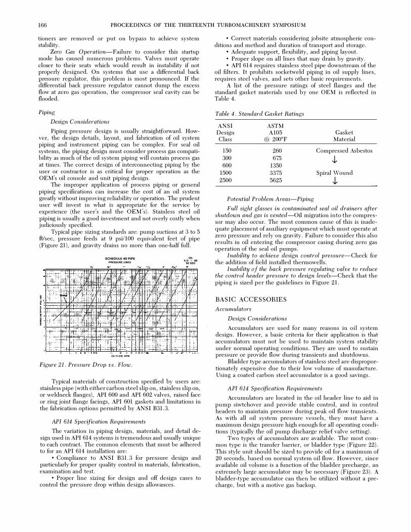
166 PROCEEDINGS OF THE THIRTEENTH TURBOMACHINERY SYMPOSIUM
tioners are removed or put on bypass to achieve system stability.
Zero Gas Operation-Failure to consider this startup mode has caused numerous problems. Valves must operate closer to their seats which would result in instability if not properly designed. On systems that use a differential back pressure regulator, this problem is most pronounced. If the differential back pressure regulator cannot dump the excess flow at zero gas operation, the compressor seal cavity can be flooded.
Piping
Design Considerations
Piping pressure design is usually straightforward. Howver, the design details, layout, and fabrication of oil system piping and instrument piping can be complex. For seal oil systems, the piping design must consider process gas compatibility as much of the oil system piping will contain process gas at times. The correct design of interconnecting piping by the user or contractor is as critical for proper operation as the OEM's oil console and unit piping design.
The improper application of process piping or general piping specifications can increase the cost of an oil system greatly without improving reliability or operation. The prudent user will invest in what is appropriate for the service by experience (the user's and the OEM's). Stainless steel oil piping is usually a good investment and not overly costly when judiciously specified.
Typical pipe sizing standards are: pump suctions at 3 to 5 ft!sec, pressure feeds at 9 psi/100 equivalent feet of pipe (Figure 21), and gravity drains no more than one-half full.
SCHEDULE 40 PIPE PAEI&UFIE UNES
OIL FLOW GPM
Figure 21 . Pressure Drop vs . Flow .
OIL S.Q. :::: .88 eo ssu
Typical materials of construction specified by users are: stainless pipe (with either carbon steel slip on, stainless slip on, or weldneck flanges), API 600 and API 602 valves, raised face or ring joint flange facings, API 601 gaskets and limitations in the fabrication options permitted by ANSI B31.3.
API 614 Specification Requirements
The variation in piping design, materials, and detail design used in API 614 systems is tremendous and usually unique to each contract. The common elements that must be adhered to for an API 614 installation are:
• Compliance to ANSI B31.3 for pressure design and particularly for proper quality control in materials, fabrication, examination and test.
• Proper line sizing for design and off design cases to control the pressure drop within design allowances.
• Correct materials considering jobsite atmospheric con-ditions and method and duration of transport and storage.
• Adequate support, flexibility, and piping layout. • Proper slope on all lines that may drain by gravity. • API 614 requires stainless steel pipe downstream of the
oil filters. It prohibits socketweld piping in oil supply lines, requires steel valves, and sets other basic requirements.
A list of the pressure ratings of steel flanges and the standard gasket materials used by one OEM is reflected in Table 4.
Table 4 . S tandard Gasket Ratings
ANSI ASTM Design A105 Gasket Class @ 200°F Material
150 260 Compressed Asbestos 300 675 .J, 600 1350
1500 3375 Spiral Wound 2500 5625 .J,
Potential Problem Areas-Piping
Full sight glasses in contaminated seal oil drainers after shutdown and gas is vented-Oil migration into the compressor may also occur. The most common cause of this is inadequate placement of auxiliary equipment which must operate at zero pressure and rely on gravity. Failure to consider this also results in oil entering the compressor casing during zero gas operation of the seal oil pumps.
Inability to achieve design control pressure-Check for the addition of field installed thermowells.
Inability of the back pressure regulating valve to reduce the control header pressure to design levels-Check that the piping is sized per the guidelines in Figure 21.
BASIC ACCESSORIES
Accumulators
Design Considerations
Accumulators are used for many reasons in oil system design. However, a basic criteria for their application is that accumulators must not be used to maintain system stability under normal operating conditions. They are used to sustain pressure or provide flow during transients and shutdowns.
Bladder type accumulators of stainless steel are disproportionately expensive due to their low volume of manufacture. Using a coated carbon steel accumulator is a good savings.
API 614 Specification Requirements
Accumulators are located in the oil header line to aid in pump siwtchover and provide stable control, and in control headers to maintain pressure during peak oil flow transients. As with all oil system pressure vessels, they must have a maximum design pressure high enough for all operating conditions (typically the oil pump discharge relief valve setting).
Two types of accumulators are available. The most common type is the transfer barrier, or bladder type (Figure 22). This style unit should be sized to provide oil for a maximum of 20 seconds, based on normal system oil flow. However, since available oil volume is a function of the bladder precharge, an extremely large accumulator may be necessary (Figure 23). A bladder-type accumulator can then be utilized without a precharge, but with a motive gas backup.

TUTORIAL SESSION ON LUBE AND SEAL O I L SYSTEMS 167
Figure 22 . Typical Accumulator .
Figure 23 . Usable Volume vs . Accumulator Precharge .
The second type is the direct contact accumulator (Figure 24). This system is used when oil flow requirements are very high, thus making bladder-type accumulators impractical.
Accumulator operation is as follows : • Oil enters check valve piped in parallel with pneumatic
cut-off valve. • As the level rises to the cut-off level, the pneumatic
valve opens and oil continues to flow through both valves . The vessel is vented until there is oil at the manual vent valve .
• Motive gas at normal header pressure is restricted from entering the oil filled tank by a pneumatic valve at the top.
• From the set of contacts in the Auxiliary Oil Pump (AOP) start switch (or a separate switch set just below AOP start pressure) , the solenoid valve is energized to open the pneumatic valve and permit entrance of the motive gas .
• Oil continues to be delivered to the header until the cutoff level is reached.
Figure 24 . Direct Contact Accumulator .
• At the cut-off level, float control closes the cut-off valve , prohibiting further flow from accumulator and preventing gas from entering the oil system.
Either the transfer barrier or direct contact accumulator should be installed in the oil system header piping as shown in Figure 25. A check valve is located upstream of the accumulator so as to prevent any backflow through the BPRV. It is important to note that both the BPRV sensing line and AOP start switch should be upstream of the check valve .
Motive gas regulators for non-precharge designs should be sized for the expected flow. The use of standard instrument regulation has caused problems in this application since the output flow is very small.
Potential Problem Areas - Accumulators
Inability of direct contact accumulators (Figure 24) to react fast enough in an upset condition-The root cause has typically been traced to improper nitrogen supply regulator sizing. Large port regulators are required for this service to supply the required gas flow in the short time span.
Another area is the location of the sensing line to the backpressure regulator. The backpressure regulator must react and pick up control after the accumulator charge is exhausted. The proper location of the sensing line is indicated in Figure 25.
Inability to observe system precharge on transfer barrier type accumulators-This is a maintenance item inherent with this type of accumulator . Additionally, bladder integrity cannot be confirmed.
One major problem with using these devices to resolve console instability is related to the two problem areas . Precharged accumulators do provide system dampening. Problems have developed when these are installed and controller proportional bands are reduced to provide extremely fast response . All is fine until the precharge is lost. Controller detuning is a more reliable solution.

168 PROCEEDINGS OF THE THIRTEENTH TURBOMACHINERY SYMPOSIUM
� : I I 0 I
I
- - - - - BEAIIING Oil SUPPLY - - - - IIEAIIINQ O I L Oilo\IN - - - - - PU M P O I SOii"IOf - _,... - - - - I'LIRCHASER'SPIPINQ - + - + - Ptlr.'IPSUCJION - Jl - JI. - TUIIBII'fE IIEL�AS£LINE - X X- TUIIIIIPaS�IIViM•'IOTOA - / - / - AII'I PIPING - 1 1 - TURIIINt SHAM JNI.(l - o - a - GA$REHRlNCI LINl - • - • - COMPR 110-SI!AI. OIL SUPPL¥ - • • - • • - COMPR ISO·SiAL OII. DflAIN - • • • - COMPR CONTAMINATiiO Oil OI!.liN
""
DO INST!WMUI T - LOCAlt.!TO
El8 INSTRUMlNT - PAf,I!LMTD
� ;M�t:�:��::TOft
ED ��m������:::���o�nAL
,!!) TH!RMOCO\II'LE !!j PMSSUIIE IIWITCH "!IJ TEMPEIIATUR!SWITCH � DtFf[II!NflAL PRES& SWITCH
_ _ _ _ j '- CHII;ll i/Alllli
� GLOII�IIALVJ; i 1<] GAT£1/All/� 1<1 1N$TIIUM�NT 1/A,lvt
. .... 1/MV� - NOI'IM,I,llYCLD!IIO ·� UUIIt.IALRlUI!f i/AI.vt z;;: BUIL T I N REUH VALVI! !:. $0LUIOIPOUMPVALIIE ::; Ttmf�·WAYVALVE (0 TF!ANSFIRI/Atvl t i P ORTROl ·'( PHEiSUIIt CONTROLIIALVE � DIFFER£NTIM PIIUS CONTROL IIAI.VIl iE' SIGHTFLQW INOICATOII
G OI'IIFict
�� T�IP & TH�OTTU:VA,LVe
0 UV£L lr.IOICA.TOFI
� II.CCUMULATOII
!t L�VEL A,LII.II¥ SWITCH
!f'<J INSTRUM�NT VALVE IBlUO PlUil)
Figure 25 . Turbine Driven Auxiliary Oil Pump .
Rundown Tanks
Design Considerations
Pressurized and gravity rundown tanks are basic accessories principally used to protect the rotating equipment during power outages, and in some cases, during unit trips
caused by the oil system. The most important consideration is that they be installed as they are designed to function.
API 614 Specification Requirements
Rundown tanks supply a quantity of oil, usually for a minimum of three minutes, during emergency shutdown or coastdown conditions. The two most common types of run� down tanks are either grade mounted pressurized, or overhead gravity feed.
The pressurized ruridown . tank is · identical to · the direct contact accumulator (Figure 24) . . Available oil is based upon normal lube and/or seal oil flow; · control · oil is usually not included in this sizing: Rundown oil routing can be preferentially mntrolled by the careful location of connections and check valves.
The second type of rundown tank commonly used is the overhead gravity feed system (Figure 26). This arrangement relies upon static oil head to provide the motive flow. The low pressure attainable with static head tanks limits their application to bearing oil rundown, typically.
The tank should be elevated to an altitude such that the equivalent static pressure head is not more than 2 to 3 psi less than the low lube oil pressure trip switch setting. As can be seen in the diagram, a check valve is included at the lube oil regulator to prevent backflow through the BPRV during rundown. A constant bleed orifice should be sized and installed such that the rundown tank charge of oil is circulated once every three hours. Experience shows that a minimum orifice diamtere of Ys in is necessary. A flow sightglass may also be installed in the return line to the reservoir to verify oil flow.
Cfo RESERVtliA:G-Q-o:--=-- - - - - - - :t I ' I
I
: r , , I
'l j ! to Bearings
J t UNIT
Figure 26 . Overhead Rundown Tank .
It should be noted that many installation sites can attain rather low ambient temperatures. Insulation as a minimum, and possibly heat tracing, is recommended in an effort to reduce or eliminate pressure losses due to viscous oil.
If a rundown tank is to be installed after initial unit commissioning, it is mandatory that oil reservoir capacities be

TUTORIAL SESSION ON LUBE AND SEAL O I L SYSTEMS 169
reviewed to verify that the additional volume of oil will be stored after rundown, and not overflow through the reservoir vents.
Potential Problem Areas
• Improper sizing of the oil reservoir to handle the rundown capacity.
• Operation with valve A open (Figure 26). • Improper tank venting.
The vacuum formed in the tank during rundown must not be allowed to develop. Typically, the installation of improper flame arrestors has restricted venting flowrate.
Overhead Seal Oil Tanks
Design Considerations
The overhead seal oil tank is used to maintain seal differential pressure and provide adequate oil flow to the compressor seals during normal operation, coastdown, and block-in in the event of an oil system failure. The principal design consideration in additional to proper instrumentation, is the cost of the pressure vessel weldment. In many cases, a vacuum degasification system will be more cost effective than the use of an intermediate bladder where severe gas contamination is expected.
API 614 Specification Requirements
The overhead seal oil tank (OHST) is used to maintain the required seal oil differential pressure to mechanical shaft seals by its static head. Use of an OHST is advantageous where low seal oil differential pressures are required (1 to 10 psid), and is quite common on sleeve seal systems. An additional function of the API 614 tank is to provide rundown seal oil flow in emergencies. As the name implies, the OHST must be located vertically to provide the required seal oil differential pressure. The API volume requirements for the overhead tank are illustrated in Figure 27 . In addition, a full length liquid level gauge should be included along with a means for internal inspection and cleaning.
EMERGENCY OPERATI N G RANGE ( 10· MINUTE SUPPLY )
LOW- LEVEL SHUTDOWN
COAST�
�11(. BLOCK- IN
.__....:;:.._ __ __.�(MINIMU ��TE SUPPLY)
August 80 draft
Figu re 27 . Overhead Seal Oil Tank Capacity .
When seal oil system demands are high, it follows that the OHST will have to be quite large to meet the API requirement of a ten minute rundown supply, although users have specified rundown times as high as 25 minutes. Of course, the oil
reservoir must be sized to handle this additional oil volume. The cost of the tank and its installation rise proportionally with the size of the overhead tank, particularly with stainless steel construction, which is a frequent user requirement.
A typical OHST control syustem is illustrated in Figure 28 . The normal oil level in the tank is monitored by a pneumatic level transmitter, which has level control and proportional band capabilities. The output signal of the level transmitter is sent to a receiver controller at the DPRV, whose function - it is to maintain the normal OHST level, relative to the transmitter signal. The gas reference signal, usually from the compressor discharge end seal, enters at the top of the tank.
32" I
' Overflow
' Gas
Reference
Seal Oi l Supply
Figure 28 . Overhead Seal Oil Tank Design .
Since the output of the transmitter is directly proportional to the liquid level in the OHST, it is practical to install pressure switches in this line which will function as low level 6P and high level 6P alarms. Alarm locations are shown in Figure 28 . In accordance with API 614, an external float-type liquid level switch is required as the low liquid level trip switch. The separate trip switch directly actuated by the oil level is an excellent safeguard.
Upon installation, the OHST should be located as close vertically to the compressor as possible. A maximum interconnecting pipe length as specified by the manufacturer is required. This line, as a minimum, should be the same size as the OHST bottom supply connection. The overhead static line should be joined perpendicularly to the seal oil feed line, and within five equivalent feet of the equipment baseplate piping connection. If ambient conditions are cold, the gas reference, the static line, and the OHST should be insulated, and possible heat traced. All of these precautions will aid in eliminating any unwanted piping losses and condensation of the process gas in the oil.
The overflow connection should be piped to the contaminated seal oil drainers. A rising loop in the gas reference line is recommended to avoid oil flow into the compressor through the gas reference line in the event of an OHST overflow, by creation of a line resistance greater than the overflow line to the drainers.
If the compressor has equalized seals, only one OHST system is necessary. However, if the seals are unequalized,
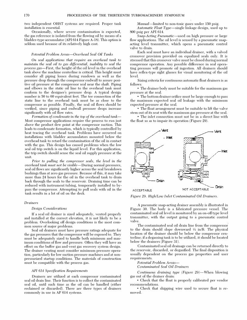
170 PROCEEDINGS OF THE THIRTEENTH TURBOMACHINERY SYMPOSIUM
two independent OHST systems are required. Proper tank installation is essential.
Occasionally, where severe contamination is expected, the gas reference is isolated from the flowing oil by means of a bladder-type accumulator (API 614 Figure A-18). This option is seldom used because of its relatively high cost.
Potential Problem Areas-Overhead Seal Oil Tanks
On seal applications that require an overhead tank to maintain the seal oil to gas differential, inability to seal the process gas-First, the height of the oil level in the overhead tank above the machine centerline is critical. This height must consider all piping losses during rundown as well as the pressure drop through the compressor endwall to assure positive oil pressure at the compressor seal near the shaft. Piping and elbows in the static oil line to the overhead tank must conform to the designer's pressure drop. A typical design number is 50 to 60 equivalent feet. The tee connection of the static line to the overhead tank must be as close to the compressor as possible. Finally, the seal oil flows should be verified, since piping and endwall pressure drops increase significantly with oil flow rates.
Formation of condensate in the top of the overhead tankMost compressor applications require the process to run just above the product dew point at the compressor suction. This leads to condensate formation, which is typically controlled by heat tracing the overhead tank. Problems have occurred on installations with bladder accumulators mounted below the overhead tank to retard the contamination of the oil in contact with the gas. This design has caused problems when the low seal oil trip switch is on the liquid level. For this application, the trip switch should sense the seal oil supply pressure at the unit.
Prior to pulling the compressor seals, the level in the overhead tank must not be visible-During normal pressures, seal oil flows are significantly higher across the seal breakdown bushings than at zero gas pressure. Because of this, it may take more than 24 hours for the oil in the overhead tank to drain back through the seals to the reservoir. Draining time can be reduced with instrument tubing, temporarily installed to bypass the compressor. Attempting to pull seals with oil in the tank results in a lot of oil on the deck.
Drainers
Design Considerations
If a seal oil drainer is sized adequately, vented properly and installed at the correct elevation, it is not likely to be a problem. Overlooking off design conditions is the most common source of major problems.
Seal oil drainers must have pressure ratings adequate for the gas pressures that the compressor will be exposed to. They must be adequately sized to handle both minimum and maximum conditions of flow and pressure. Often they will have an effect on the buffer gas and vent gas recovery system design. The drainer venting must consider minimum pressure operation, particularly for low suction pressure machines and at nonpressurized startup conditions. The materials of construction must be compatible with the process gas.
API 614 Specification Requirements
Drainers are utilized at each compressor contaminated seal oil drain line. Their function is to collect the contaminated seal oil, until such time as the oil can be handled (either reclaimed or discarded). There are three types of drainers commonly in use in AP 614 systems.
Manual-limited to non-toxic gases under 150 psig. Automatic Float Type-single linkage design, used up to
800 psig per API 614. Snap-Acting Pneumatic-used on high pressure or large
flow applications. The oil level is sensed by a pneumatic snapacting level transmitter, which opens a pneumatic control valve to drain.
Each seal must have an individual drainer, with a valved crossover provision provided on equalized seals only. It is stressed that this crossover valve must be closed during normal compressor operation. Any possible difference in seal operating pressure will promote oil ingestion. All drainers should have reflex-type sight glasses for visual monitoring of the oil level.
Sizing criteria for continuous automatic float drainers is as follows:
• The drainer body must be suitable for the maximum gas pressure at the seal.
• The bottom drainer orifice must be large enough to pass the maximum expected seal oil leakage with the minimum expected pressure at the seal.
• The float arrangement must be suitable to lift the valve stem out of its seat with the maximum gas pressure at the seal.
• The inlet connection must not be in a direct line with the float so as to impair its operation (Figure 29).
O �il ��� ""'"' tl ..• ....,?�
�
Vent
lriet
� Drain ACCEPTABLE NOT ACCEPT ABLE
Figure 29 . High/Low Inlet Contaminated Oil Drainers .
A pneumatic snap-acting drainer assembly is illustrated in Figure 30. The body is a fabricated pressure vessel. The contaminated seal oil level is monitored by an on-off type level transmitter, with the output going to a pneumatic control valve.
The contaminated seal oil drain line from the compressor to the drain should slope downward Y2 in/ft. The physical location of the drainer should be below the compressor centerline; if a degassing tank is to be utilized, it should be located below the drainers (Figure 31).
Contaminated seal oil drainage can be returned directly to the reservoir, discarded, or degasified. The final disposition is usually dependent on the process gas properties and user requirements.
Potential Problem A reasContaminated Seal Oil Drainers
Continuous draining type (Figure 29)-When blowing gas out of the drainer drain:
• Check that the float is properly calibrated per vendor recommendations.
• Check that shipping wire used to secure float is removed.

TUTORIAL SESS ION ON LUBE AND SEAL O I L SYSTEMS 171
LEVEL rB CONTROLlER
� '
� INLET !"
'\.
Figure 30 . Pneumatic Valve Drainers .
Compressor
ORIFlCE
J :�
V8'JT
Lube Oil Reservoir
Figure 31 . Contaminated Drainer Installation .
• Check for valve set erosion. • Where drainers are used in applications with minimum
contaminated seal oil leakage rates , prefilling may be required. When blowing oil out of the drainer vent: • Check that the float is properly calibrated per vendor
recommendations. • Check for a damaged float or loose linkage. Pneumatic snap-acting drainers (Figure 30)-When
blowing gas out of the pneumatic valve: • Check the level control set point and proportional band. • In the case of high pressure applications , the valve
closing speed may have to be increased. Increasing the size of the valve actuator atmospheric vents has worked satisfactorily.
• Check for valve set erosion. • Check that a snap-acting controller is installed.
Proportional type controllers should not be used. No level in sightglass-To verify the actual level in any
sightglass , the handwheel must be cycled to unseat the ball check used to protect the installation in case of a sightglass failure.
Full sightglass level-Check for proper drainer calibration. For occurrance of this phenomenon during zero gas operation:
• Check for proper equipment installation (Figure 31) . • Check that the drainer valve design will pass the pre
dicted contaminated leakage rate at zero gas differential. Flow will be a function of the oil head developed.
Degassing Tanks
Design Considerations
Seal oil contamination is a sophisticated issue, and while atmospheric degass ing is not a universal answer in many applications , it is an effective technique in reclaiming contaminated (inner) seal oil. Degassing tanks are:
• Atmospheric vessels and must not be pressurized as they are part of a gravity drain system,
• Should be protected against overpressurization due to failures of the drainer, and
• Should not be vented into flare system indiscriminately. The most recent designs have eliminated the gas tight
baffie and breather connection in favor of a single larger vent. Where the vent and breather are provided, both must be piped to a safe venting area, since the vapor space above the oil is process gas laden.
Degassing tanks provide a means of reclaiming contaminated seal oil by releasing entrained process gases prior to returning the oil to the reservoir. For light hydrocarbons and gases that are readily separable for the hydrocarbon mixture of the oil , atmospheric degassing can maintain the oil properties satisfactorily. For heavier hydrocarbons and gases such as hydrogen sulfide, the atmospheric tank provides only partial degassing.
API 614 Specification Requirements
The API 614 requirements for a degassing tank are: • A gas tight baffie dividing the tank into two sections. • Heaters , either electric or steam, should be supplied.
Electric heaters should have a maximum watt density of 1 5 watts per square inch.
• The tank should be sized for the maximum expected seal oil leakage for all machines.
• A sight glass and vent should be provided (2 in min). A typical degassing tank is illustrated in Figure 32. The
theory of operation is that any reduction in the gas partial pressure is accompanied by an immediate release of some of the dissolved gas. The contaminated oil is drained from the contaminated seal oil drainers to the degass ing tank, where it is distributed across a sloped, perforated sparging tray. Droplets form , with a release of gas , and fall into the bottom of the tank. The oil in the tank should be heated to 180°F to 200°F. The gas released from the pressure breakdown from the seal oil drainers , that is separated by the sparging tray and is given off from the heated oil in the tank, are vented to atmosphere through a stand pipe.
The venting of the degassing tank is a frequent problem area. Oil from the degassing tank flows to the oil reservoir by gravity, and back pressure on the tank from the vent system must be avoided.
Where the tank is vented to a header that may be pressurized, it must not only be provided with proper overpressurization protection, but the impact on the contaminated seal oil drain and return system must be reviewed carefully.
Breather \
Outlet ""'11 _ _
, , _-:::. .I
- , r , , ,
Vent
/
:F·:::::. -:.= = =------ - - -
, , , , I I , , ' I Ll
Figure 32 . Degassing Tank .
Purge
---- Heater
---- Drain

172 PROCEEDINGS OF THE THIRTEENTH TURBOMACHINERY SYMPOSIUM
A degassing tank size of 15 gallons per compressor body has proven satisfactory for many compressor trains.
Prior to start-up of the compressors, it is recommended that the degassing tank be filled with oil. This may prevent an electric immersion heater failure. A level switch interlocked with the electric heater is a common option.
Potential Problem Areas - Degassing Tanks
Electric heater failure-Be sure to manually fill the tank before energizing the heater.
Blowing gas out rtjservoir vent-Check that the degassing tank is not vented to a flare system that becomes pressurized during upset conditions.
Tank pressurization-This is not a pressure vessel and should be properly vented.
btl Purifiers
Design Considerations
Coalescers and centrifuges are effective in removing free water from lube oil systems, arid seal systems where the gas contamination can be controlled by atmospheric degassing (limited to lighter hydrocarbons without H2S) . Where atmospheric degassing is ineffective, (heavier HCs and/or Hss) vacuum degassing can be applied. If significant water is preSent, the dehydrator option with the vacuum degasifier is appropriate (turbine drive or excessive condensation) .
For a lube system with free water contamination only, either a coalescer or centrifuge will perform well. The centrifuge will break oil emulsions that the coalescer can not. Only the vacuum system is effective as a reconditiorier where there is severe gas contamination (reduction in flash point and viscosity).
Integrating the vacuum system into the oil console design will significantly reduce its cost. The pay back period in most cases is less than two years.
API 614 Specification Requirements
There are three commonly used methods of recondition-ing oil :
• Coalescing filtration (coalescer) • Centrifugal purification (centrifuge) • Vacuum degasification/dehydration Basic Description of Oil Conditioning Methods-The
coalescer operates as a fine filter. It mechanically separates free water from the oil stream allowing it to collect in the vessel sump for manual draining. The coalescer can produce effiuents with a water content equal to that of dehydrating or centrifuging at moderate water loadings. However, the coalescer can be susceptible to fouling by surface emulsions. The coalescer is ineffective for dissolved water and gases. It is the simplest and least expensive.
The centrifuge operates by centrifugal force, mechanically separating immiscible liquids and solids of differing densities. As applied to lubricating oil conditioning, the centrifuge is used as a "purifier, " separating solid particles and free water from the oil. Water and clean oil are continuously discharged, while the sludge must be removed from the bowl by hand. Upon occasion, a "clarifier" may be specified by users rather than a purifier. The clarifier removes solid particles and a very small amount of water, but continuously discharges only clean oil. The centrifuge effectively separates free water from the oil and sludge. It is ineffective for dissolved water and gases. The centrifuge is much more expensive than a coalescer and requires more maintenance.
The vacuum degasser vaporizes free and dissolved water, air, and gases (hydrocarbon and H2S) in a vacuum vessel. The
resultant vapors are drawn off and expelled by a vacuum pump. Where significant amounts of waste and other condensibles are present, a dehydrator option consisting of a condensor and condensate tanks are added, (degasser/dehydrator) to avoid contamination of the vacuum pump oil. Vacuum degasification is the most effective oil conditioning method and the only effective treatment for severe contamination . A vacuum degassing system is more expensive than a centrifuge, and perhaps a little more difficult to maintain.
Instrumentation
Design Considerations
The importance of the system instrumentation for monitoring operation, alarming abnormal conditions, and for emergency shutdowns is obvious. The controls must enable the oil system to respond to dynamic conditions both internal and external to the system. OEMs have accumulated a great deal of experience in the unique aspects of oil system instrumentation and system reSponse. Proper coordination and meaningful discussions between user, contractor, and OEM will assure a functional system.
API 614 Specification Requirements
A complete array of instrumentation is J1.ecessary to provide reliable operation of an oil system, abnormal operation alarms, and automatic shutdo\vns . Pressm:e and temperature inidicators, liquid level gauges, and sight flow indicators provide visual confirmation of console performance.
Switches-'-provide an electric signal to activate art alarm light, start an oil pump, or shut down a rotating string. Certain fundamental functions must be monitored on an oil system.
The reservoir should have a liquid level switch which triggers an alarm at minimum oil level. This indicates that oil must be added to the system, and that an oil leak may exist.
With electric heaters, it is prudent to interlock heater controls and level switches. The auxiliary oil pump may have a pressure switch which indicates that the pump is operating. A typical set point would be 25 percent of the relief valve set pressure, or 25 percent of the centrifugal pump shutoff head. The switch should activate on rising pressure.
As previously discussed, oil filters should be changed when the differential pressure has risen 15 psid above clean. Typical factory alarm settings are as follows:
20 psid across filter only 25 psid across filter/transfer valve 35 psid across filter/cooler/transfer valve However, a more accurate field setting can be made by
observing the clean element pressure drop at design oil flow and temperature, and then adjusting the switch to alarm at 1 5 psid above that value.
In the controlled header arrangement, the start auxiliary oil pump pressure switch should be located downstream of the filters, but upstream of any accumulators. A typical set point is 15 psi below the controlled header pressure, but may be as high as five to seven percent of header pressure on high pressure oil systems. Switch actuation is on falling oil pressure. It should be noted that a locking relay is required in the start AOP circuitry, such that when the auxiliary oil pump renews the system header pressure, the switch actuation, when returning to normal, does not shut down the oil pump drive. The system design should be such that start AOP is to occur, due to a fault. The manual reset is to ensure operator· attention and prevent cycling.
Lubrication lines must have pressure switches which alarm and trip on falling lube oil pressure. Typical settings, assuming a lube oil delivery of 18 psig, would be a 13 psig

TUTORIAL SESSION ON LUBE AND SEAL OIL SYSTEMS 173
alarm and an 1 1 psig trip. Time delays are user options. They should be limited to a few seconds.
Likewise, seal oil delivery lines must have differential pressure switches which alarm and trip on falling seal oil differential pressure. Seal oil is the high reference, process gas is the low reference. Typical settings, assuming a design differential pressure of 50 psid, would be 30 psid to alarm, and 20 psid to trip. Again, time delays are a user option and they should be limited to a few seconds.
A temperature switch may be included downstream of the oil coolers to alarm on rising oil temperature. Typical set points would be l5°F to 20°F above design oil delivery temperature.
As with all electrical devices, switches must be suitable for the National Electric Code (NEC) area classification and weather conditions.
Pressure Gauges-are necessary to accurately determine console performance, to aid in setting switches and controls, or troubleshoot any abnormalities. Typically, a pressure gauge should be installed upstream of the coolers to monitor oil pump discharge press�,�re. Likewise, a gauge should be instalkd downs.tream of the filters to monitor the header pressure, and provide a reference for start AOP switch test The above two instruments also act as a check on the differential pressure gauge installed across the oil filters.
Lube oil pressure gauges should be provided, as well as a seal oil pressure gauge, and a seal oiUgas differential pressure gauge. .
Thermometers-are utilized to monitor an oil system.'s cooling efficiency or inefficiency, and to diagnose possible equipment problems. Thremometers should be mounted in the oil reservoir, upstream and downstream of the oil coolers, and at each of the oil throwoff lines of the machinery bearings and/or seals. Stainless steel thermowells are recommended in an effort to ease maintenance and replacement.
Sight Flow Indicators'-should be installed at every oil drain line of the machinery, and in the overhead rundown tank bleed return line .
Liquid Level Indicators-'-Should be installed on the oil reservoir, direct contact accumulators, seal oil drainers, over· head seal oil tanks, and degassing tanks.
This is the typical instrumentation. In addition, there are the basic instrumentation needed to control the systems operation. Users will require whatever additional instrumentation that is necessary to provide operators with every means of . maintaining reliable oil system operation . This list is only meant to provide a guide to nominal instrumentation requirements.
Potential Problem Area - Switches
Motor Driven Auxiliary Oil Pump Cycling On-Off-OnCheck that a locking relay was installed in the auxiliary oil pump start circuit. This circuit should operate in such a manner that once the pump is energized, it must be manually reset.
"Hand-Off-Auto" Switches-for motor driven auxiliary oil pumps left in the "off' position.
Unit Trips Before Alarm-The alarm test orifice required by API should be checked for integrity.
Switch Failures- Specifying an explosion proof switch may permit the design not to be waterproof. Additionally, numerous failures have been traced to improper conduit sealing.
FACTORY INSPECTION AND TESTING
In order to provide a quality oil system on site, it is logical that specific inspection and testing procedures be followed by
the manufacturer. API 614 lists specifications which must be adhered to by the supplier, but factory quality control is usually much more comprehensive.
During assembly of the console and its components, numerous checks are made on weld quality, cleanliness, customer connection locations, wiring, and piping stress.
Piping should be removed and chemically cleaned after being fit and welded. Chemical cleaning should include an alkaline bath for degassing, an acid bath to remove corrosion and in ill scale, · and finally a rust inhibiting treatment, chemical cleaning and preservation for stainless steel.
· The piping should then be totally reassembled for hydrostatic testing. If possible, the whole console should be hydrostatically tested as a unit; using oil. The test pressure should be 1 V2 times the oil pump relief valve set presure, or 1% times the centrifugal .oil pump shutoff head. If loose piping must be hydrostatically tested separately, the test pressure should be that which is specified for the lowest rated flange on the piece . Any non-pressurized piping, such as pump suctions or drain lines, should be tested at approximately 10 psig. A successful hydrostatic test should maintain the test pressure for a minimum of 30 minutes.
After a successful hydrostatic test, the console should now be readied for flushing and cleanliness inspection. API specifies minimum cleanliness standards based dn piping size. During the oil flush, filter elements should be changed as necessary, piping should be vibrated, and the oil system should be thermally cycled (l60dF maximum) to assure complete cleanliness. Flushing screens (usually 100 mesh stainless steel) are to be placed at all delivery lines.
Manufacturers typically offer three grades of mechanical testing. The type of test desired is a decision of the customer, since performance testing usually involves a cost addition.
Mechanical Run
1 . The motor driven pump is operated . 2. Console is flushed to API cleanliness standard. 3, After console meets cleanliness standards it will run for
four hours during which period, • Both relief valves will be set using motor driven
pump discharge. • Entire unit will be visually checked for leaks. • Correct physical arrangement of all components is
visually verified. 4. Clean filter cartridges are installed after test. Generally, no other components (auxiliary pump, control
valves, switches, gauges, or other instruments) will be cali" brated, tested, or demonstrated.
Console Performance Test
The console performance test option demonstrates the mechanical integrity of the entire console. In addition to all items in the Standard Mechanical Run, a single successful demonstration of each of the following functions is made during the four-hour run after the console has been flushed .
The second pump is operated and a proper automatic switchover from main to auxiliary pump is demonstrated. For this test, the AOP start device and the accumulator(s), if used, are set to predicted pressure. Console header pressure is properly measured.
The ability of each regulator to fully stroke will be demonstrated manually by manipulation of by-pass valves, isolating valves, or transmitter signal as necessary .
The ability of each switch to function will be demonstrated either manually or by pressure variation. Since most settings must be finally made under field conditions, no attempt will be

174 PROCEEDINGS OF THE THIRTEENTH TURBOMACHINERY SYMPOSIUM
made to calibrate or set instruments or switches other than those necessary to conduct the above test.
A filter/cooler switchover will be demonstrated. Associated switches or instruments will not be calibrated or set.
Oil flow and pressure at each outlet is metered and measured to show proper control at expected field operating conditions.
Differential regulation, through signals from system differential pressure transmitters, will be demonstrated using controlled nitrogen pressure to simulate compressor gas pressure. However, in no case will overhead seal tanks be erected to provide differential control. Those regulators controlled by overhead seal tank levels will be manually regulated to required flows and pressures.
This test is strictly a console test and is run separate from the rotating string. It will fully meet the requirements of API. A noise survey is included.
Performance Test With Rotating String
This test is quite similar to the separate console performance test, including all operations and functions in both the standard mechanical run and the console performance test. Demonstrations or functions automatically performed by running with the rotating machinery are not manually performed as in the other test options.
Unless the string is operated at actual conditions, and even then, field installation piping and service conditions cannot be duplicated. There is little advantage in a string test.
The console will be used to serve the rotating string during the mechanical or performance test of the string. All possible functions will be demonstrated within the limits of the rotating string test. It must be noted that it may not be possible to demonstrate full seal oil pressure unless a gas loop test at design pressure is purchased on the compressor(s).
Pressure will be monitored at each oil delivery point, but the flow through the various circuits will not be metered.
As in the separate console performance test, overhead seal tanks will not be erected and associated regulators will be manually controlled or bypassed to obtain proper differentials. It must be recognized that the relative location and elevation of the console and the rotating string in the field will probably not be reproduced on the test floor. This will require field regulator adjustment and switch setting to actual final values.
After all testing has been completed, and the console has been accepted, shipping preparation begins. The following checklist can be used as a guideline:
• Remove, inspect, clean and coat with rust preventative the turbine pump driver bearings.
• Discard used filter cartridges, replace with new. Tag filter housings stating that new filter elements were installed.
• Manual or pneumatic control valves should be positioned so as to reduce the overall console dimensions for shipping purposes, and to reduce the likelihood of damage. These should be relocated prior to commissioning.
• All customer gauges (other than rack mounted) should be removed and shipped separately.
• All liquid level transmitters and controllers should be removed and shipped separately.
• All exposed machined surfaces, tank openings, and exposed flange faces should be protected with a rust preventative.
• All unprotected threaded openings should be fitted with pipe plugs or caps.
• Loose piping should be tagged to aid in field assembly. • Oil pump drive couplings should have the spacer re-
moved and bound to the respective pump or driver. • All gauge glass and nameplates should be protected. • All carbon steel piping and fittings should be painted. • Filters, coolers, large valves, gauge panels, lengthy
stretches of pipe, and flexible joints should be rigidly held with temporary bracing, which is to be removed upon installation.
In general, quality control must be monitored from initial console assembly to the time the unit ships. The user should ensure that the OEM has the policies, procedures, and instructions for implementing the quality requirements of the contract, maintains the necessary measurement tools and laboratory facilities and has the people to support this plan.
A quality plan for oil consoles is extensive, sometimes in excess of 200 pages, and has many inspection points for the typical lubrication and seal oil system.
CONCLUSION
The days of referring to a lube and seal oil console of nothing more than a "necessary evil, " have passed. The lube and seal oil console is an integral part of the equipment package, as well as the overall end user process, and must be engineered as such.
Even with the most advanced process rotating equipment, many plant shutdowns have traced back to simple console problems such as improperly calibrated seal oil controllers, differential pressure switches and relief valves.
A guideline intended to serve as an aid in designing, specifying, and troubleshooting typical oil systems has been presented. Specific console installations or applications should be addressed on an individual basis.

PROCEEDINGS OF THE THIRTEENTH TURBOMACHINERY SYMPOSIUM 1 75
] ack N . Essinger is an Engineering C onsultant with S hell Oil Company, Houston, Texas, and is assigned to the Machinery Group of Shell's Engineering Services Department . In this assignment, he is involved in the specification, evaluation , installation and startup of new rotating equipment, and in troubleshooting of existing systems . Mr . Essinger has been employed in this line of work since graduating from A rizona
State University with a B . S . degree in i\!fechanical Engineering in 1 960 .
He is a member of ASME and ASM, and he is a registered professional engineer in the S tate of Texas . He is a member of the Advisory Committee of the Turbomachinery Symposium .
Peter] . Beaty graduated from Villanova Unicersity in 1 966 with a B .S . degree in Mechanical Engineering . He joined the Engineering Department of E . I . du Pont de Nemours & Company and has held a number of assignments incolving mechanical equipment and development . He spent six years as Senior Engineer in du Pont's regional consulting f�{fice located near Nashville dealing with rotating machines, mechanical �lesign,
vibration analysis, and turhomachinery prohlems . .
Mr . Beaty was assigned in 1 977 to the Design Division of the Engineering Department where he is a Project Enginee1-involved with the application of turbomachinery, including specification , procurement, design audit, installation, and startuJJ . He is a member (if' Tau Beta Pi, Pi Tau S igma, ASME, API, and i s a registered professional engineer in the State of Tennessee . He has served on API task forces for centrifugal compressors , gears, and lube, seal, and control oil systems .
Michael D 'Innocenzio is a Senior Engineering Associate with Exxon Research and E ngineering C ompany, Florham Park, New .Jersey . He is responsible for the application, specification and selection of mechanical equipment for Exxon's worldwide facilities . During his 26 years with the company, he has also been involved with machinery field startup and troubleshooting assignments .
Mr . D'Irmocenzio holds B . S . and M . S . degrees in Mechanical Engineering from Purdue University and New Jersey Institute of Technology, respectively . Prior to joining Exxon , he was engaged in jet engine research and development activities at Curtiss Wright Corporation . He has heen a member of the API Subcommittee on Mechanical Equipment .

176 PROCEEDINGS OF THE THIRTEENTH TURBOMACHINERY SYMPOSIUM