rover shield - robotshop | robot store | robots | robot ... · the dfrobotshop rover shield is the...
TRANSCRIPT

ROVER ShiELD
User Guide v1.0 v1.0 Oct 1, 2014
This guide is only available in English Ce manuel est seulement disponible en Anglais
RobotShop Inc. www.RobotShop.com

Description The DFRobotShop Rover Shield is the ideal “all in one” shield for small, Arduinobased mobile robot development. The shield allows you to power your Arduino using a 3.7V LiPo battery and even has a 3.7V LiPo charger onboard, allowing you to charge the battery via USB. The onboard L298P Hbridge (dual brushed DC motor controller) is perfect for controlling two small, low voltage gear motors such as those offered by Tamiya, and allows for full control over speed and direction. Additional features include a universal IR receiver, XBee headers and analog pins broken out (for easy connection to sensors). The shield is designed to be used with a shieldcompatible microcontroller such as the Arduino Duemilanove / Uno (sold separately). We do not suggest using the shield with a breadboard or with other shieldcompatible microcontrollers which may not have the same pinout or voltage as a standard Arduino. When stacking multiple shields, or when using the shield with an Arduinobased board which has additional builtin features, be sure to check the pins which are used, as some may interfere with one another. Key Features
Dual DC motor controller (3.5 to 9V and up to 2A per channel) Onboard voltage regulator 3.7V LiPo battery charger (via micro USB connector) XBee headers 38Khz Universal IR receiver (~10m unobstructed range) On/Off switch Analog headers
Package Contents
One DFRobotShop Rover Shield (fully assembled with stacking headers) Additional Items Needed (sold separately)
Arduino shieldcompatible microcontroller (Arduino Uno for example) Optional Items (sold separately)
3.7V LiPo battery (suggested up to 2000mAh) Micro USB cable for charging LiPo battery IR remote control Wireless device w/ XBee footprint Motors and associated wiring
RobotShop Inc. www.RobotShop.com

Pinout The following pins are permanently connected. If you wish to stack other boards, be sure to check that the same pins are not used for each shield. If you choose not to use specific features, such as the onboard motor controller, then you can still send signals via the I/O pins to the other shields.
Digital pin 0: Connected to XBee Tx pin (serial communication)* Digital pin 1: Connected to XBee Rx pin (serial communication)* Digital pin 5: E2 speed control Digital pin 6: E1 speed control Digital pin 7: M2 direction control Digital pin 8: M1 direction control Digital pin 9: IR receiver pin (not the sensor is a receiver only, it cannot transmit)
* When uploading code to the Arduino board, it is important that the Xbee or other related module is not connected, freeing up the serial lines (digital pins 0 and 1 on the Arduino).
Arduino “Arduino is an opensource electronics prototyping platform based on flexible, easytouse hardware and software. It's intended for artists, designers, hobbyists, and anyone interested in creating interactive objects or environments.”
www.arduino.cc There are many ways to learn how to code in Arduino. We suggest one or more of the following:
www.arduino.cc > “Learning” and “Reference” categories Arduinorelated books http://www.robotshop.com/books.html
Software Installation / Setup
1. Install Arduino software: www.Arduino.cc 2. Download IR Library: http://www.robotshop.com/content/ZIP/arduinolibrarydfr0107.zip 3. Unzip / extract IRemote folder to Arduino > Libraries 4. Open Arduino software & import IR Library as follows: 5. Sketch > Import Library > Add Library (search for IRemote folder)
You are not restricted to using the IR library, though it is the only “official” code supported at this time by DFRobot and RobotShop.
RobotShop Inc. www.RobotShop.com

Features Dual DC Motor Controller / Hbridge
These two pairs of screw terminals are for connecting two small DC motors. M1 and M2 are silkscreened on the shield. The chip used, the L298P, is intended to be used with brushed DC motors and can provide at most 2A per channel. When running DC brushed motors, be sure to leave them time to cool down as the duty cycle (time in operation vs time cooling off) is around 25%. IR Receiver
This is the infrared receiver. The sample code below works with many (though not all) infrared remote controls. We suggest a few IR remotes (such as a universal TV remote) to see if you can read the signal with the code provided below. Note that the IR receiver will get interference from normal lights, the sun and other sources of infrared light. These sources will create signals on their own, and may interfere with signals from IR devices. Infrared works best when an IR remote is pointed directly at the rounded (receiving) surface of the IR receiver, though it will detect reflected IR signals from other surfaces. When using it to control a mobile robot, we strongly suggest doing so in a room with as few other IR sources as possible.
RobotShop Inc. www.RobotShop.com
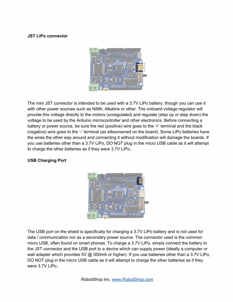
JST LiPo connector
The mini JST connector is intended to be used with a 3.7V LiPo battery, though you can use it with other power sources such as NiMh, Alkaline or other. The onboard voltage regulator will provide this voltage directly to the motors (unregulated) and regulate (step up or step down) the voltage to be used by the Arduino microcontroller and other electronics. Before connecting a battery or power source, be sure the red (positive) wire goes to the ‘+’ terminal and the black (negative) wire goes to the ‘’ terminal (as silkscreened on the board). Some LiPo batteries have the wires the other way around and connecting it without modification will damage the boards. If you use batteries other than a 3.7V LiPo, DO NOT plug in the micro USB cable as it will attempt to charge the other batteries as if they were 3.7V LiPo.. USB Charging Port
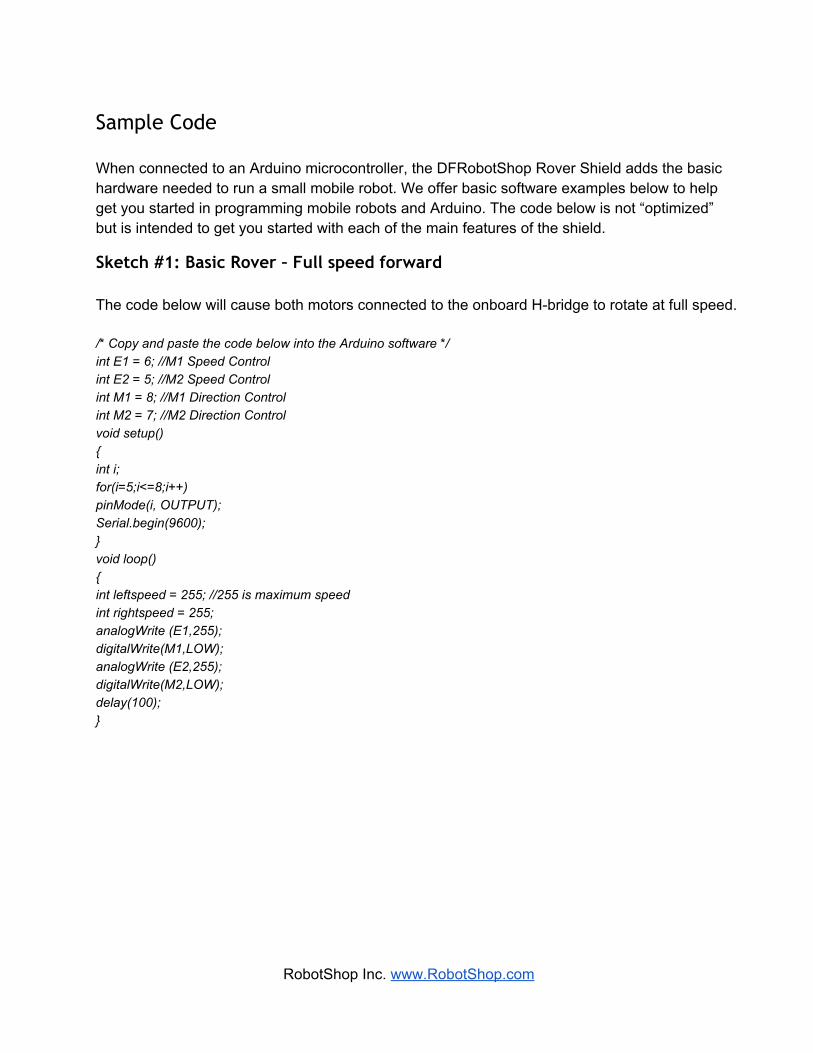
The USB port on the shield is specifically for charging a 3.7V LiPo battery and is not used for data / communication nor as a secondary power source. The connector used is the common micro USB, often found on smart phones. To charge a 3.7V LiPo, simply connect the battery to the JST connector and the USB port to a device which can supply power (ideally a computer or wall adapter which provides 5V @ 500mA or higher). If you use batteries other than a 3.7V LiPo, DO NOT plug in the micro USB cable as it will attempt to charge the other batteries as if they were 3.7V LiPo..
RobotShop Inc. www.RobotShop.com

XBee Headers
The XBee headers included on the board are ideally used for wireless communication. They are compatible with normal series 1 and series 2 XBee modules, as well as many Bluetooth and WiFi modules which have an XBee footprint. Be sure to install the module in the same orientation as the silkscreen on the board. When uploading code to the microcontroller, either the wireless XBee module needs to be removed, or the shield itself needs to be removed.
The On/Off switch essentially connects the battery to the rest of the board. Rather than disconnecting the battery to power the robot, you now only need to flip a switch.
RobotShop Inc. www.RobotShop.com

Power Pins
In addition to the JST connector, there are two unpopulated connections which allow you to solder your own connector or cable. Reset
The reset button provides the same functionality as the reset button found on the Arduino microcontroller, but saves you the trouble of having to remove the shield to access the one on the Arduino. Turning the board Off and then On again has the same effect.
RobotShop Inc. www.RobotShop.com
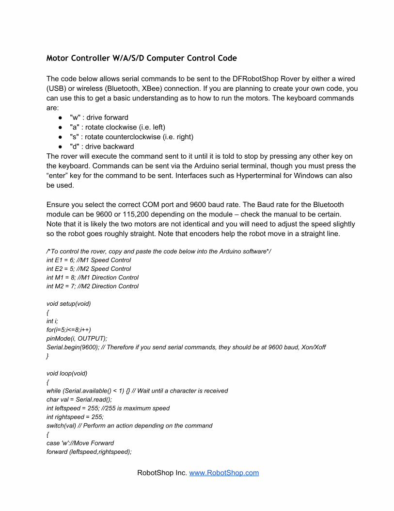
Sample Code When connected to an Arduino microcontroller, the DFRobotShop Rover Shield adds the basic hardware needed to run a small mobile robot. We offer basic software examples below to help get you started in programming mobile robots and Arduino. The code below is not “optimized” but is intended to get you started with each of the main features of the shield.
Sketch #1: Basic Rover – Full speed forward The code below will cause both motors connected to the onboard Hbridge to rotate at full speed. /* Copy and paste the code below into the Arduino software */ int E1 = 6; //M1 Speed Control int E2 = 5; //M2 Speed Control int M1 = 8; //M1 Direction Control int M2 = 7; //M2 Direction Control void setup() int i; for(i=5;i<=8;i++) pinMode(i, OUTPUT); Serial.begin(9600); void loop() int leftspeed = 255; //255 is maximum speed int rightspeed = 255; analogWrite (E1,255); digitalWrite(M1,LOW); analogWrite (E2,255); digitalWrite(M2,LOW); delay(100);
RobotShop Inc. www.RobotShop.com
Motor Controller W/A/S/D Computer Control Code The code below allows serial commands to be sent to the DFRobotShop Rover by either a wired (USB) or wireless (Bluetooth, XBee) connection. If you are planning to create your own code, you can use this to get a basic understanding as to how to run the motors. The keyboard commands are:
"w" : drive forward "a" : rotate clockwise (i.e. left) "s" : rotate counterclockwise (i.e. right) "d" : drive backward
The rover will execute the command sent to it until it is told to stop by pressing any other key on the keyboard. Commands can be sent via the Arduino serial terminal, though you must press the “enter” key for the command to be sent. Interfaces such as Hyperterminal for Windows can also be used. Ensure you select the correct COM port and 9600 baud rate. The Baud rate for the Bluetooth module can be 9600 or 115,200 depending on the module – check the manual to be certain. Note that it is likely the two motors are not identical and you will need to adjust the speed slightly so the robot goes roughly straight. Note that encoders help the robot move in a straight line. /*To control the rover, copy and paste the code below into the Arduino software*/ int E1 = 6; //M1 Speed Control int E2 = 5; //M2 Speed Control int M1 = 8; //M1 Direction Control int M2 = 7; //M2 Direction Control void setup(void) int i; for(i=5;i<=8;i++) pinMode(i, OUTPUT); Serial.begin(9600); // Therefore if you send serial commands, they should be at 9600 baud, Xon/Xoff void loop(void) while (Serial.available() < 1) // Wait until a character is received char val = Serial.read(); int leftspeed = 255; //255 is maximum speed int rightspeed = 255; switch(val) // Perform an action depending on the command case 'w'://Move Forward forward (leftspeed,rightspeed);
RobotShop Inc. www.RobotShop.com
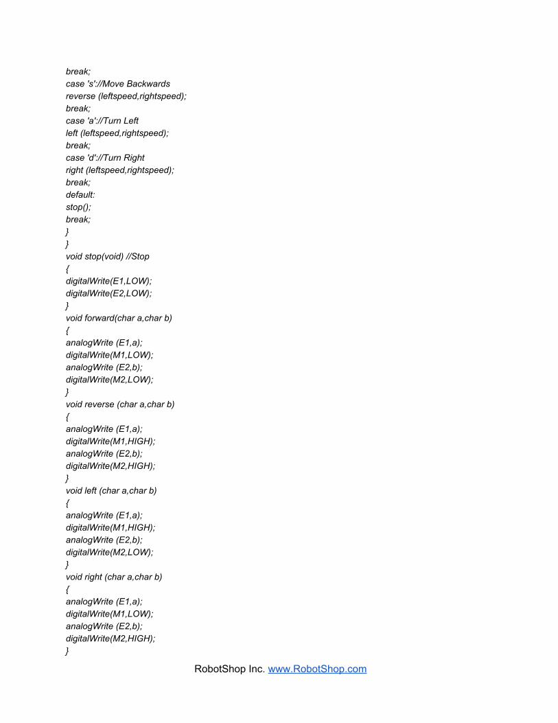
break; case 's'://Move Backwards reverse (leftspeed,rightspeed); break; case 'a'://Turn Left left (leftspeed,rightspeed); break; case 'd'://Turn Right right (leftspeed,rightspeed); break; default: stop(); break; void stop(void) //Stop digitalWrite(E1,LOW); digitalWrite(E2,LOW); void forward(char a,char b) analogWrite (E1,a); digitalWrite(M1,LOW); analogWrite (E2,b); digitalWrite(M2,LOW); void reverse (char a,char b) analogWrite (E1,a); digitalWrite(M1,HIGH); analogWrite (E2,b); digitalWrite(M2,HIGH); void left (char a,char b) analogWrite (E1,a); digitalWrite(M1,HIGH); analogWrite (E2,b); digitalWrite(M2,LOW); void right (char a,char b) analogWrite (E1,a); digitalWrite(M1,LOW); analogWrite (E2,b); digitalWrite(M2,HIGH);
RobotShop Inc. www.RobotShop.com

Encoders - Counting The code below simply counts the number of changes as viewed by a single channel analog encoder. The suggested encoder (Tamiya Encoder Kit) uses a disc with 8x white sections and 8x cutouts. This will provide a count of 16 per 360 degree rotation. It is up to you to optimize and integrate it with your code. The code also sends commands to the motors to have them rotate. int rawsensorValue = 0; // variable to store the value coming from the sensor int sensorcount0 = 0; int sensorcount1 = 0; long count = 0; void setup() int i; for(i=5;i<=8;i++) pinMode(i, OUTPUT); Serial.begin(9600); int leftspeed = 255; //255 is maximum speed int rightspeed = 255; void loop() analogWrite (10,255); digitalWrite(12,LOW); analogWrite (11,255); digitalWrite(13,LOW); delay(20); rawsensorValue = analogRead(0); if (rawsensorValue < 600) //Min value is 400 and max value is 800, so state chance can be done at 600. sensorcount1 = 1; else sensorcount1 = 0; if (sensorcount1 != sensorcount0) count ++; sensorcount0 = sensorcount1; Serial.println(count);
RobotShop Inc. www.RobotShop.com

Determining IR Codes The code below will help you determine the values for the signals being sent from an IR remote control. Note that the code does not work for all IR remotes and may need to be customized. Copy and paste all of the code (in italics) below into the Arduino window (as a new “sketch”). Note that this code will only work if you have the IRemote library successfully installed (see instructions above). #include <IRremote.h> #include <IRremoteInt.h> IRrecv irrecv(9); // digital pin 9 on the shield is permanently connected to the IR receiver decode_results results; void setup() Serial.begin(9600); // This determines the baud rate irrecv.enableIRIn(); // Enable the receiver void loop() if (irrecv.decode(&results))
Serial.println(results.value, DEC); // alternatively use HEX rather than DEC irrecv.resume(); // Receive the next value
Once you have verified and uploaded the code, open the serial terminal within the Arduino IDE, keeping the Arduino connected to the computer. Cover the IR receiver with your hand from all sides except the one with the round part which faces outwards (to limit IR interference from lights, sun and other sources). Aim your IR remote at the receiver and press one button. You should see a value appear in the serial terminal window only when you press a button. Press the button a few times to ensure it’s the correct value, and take note of it in a file (the button, and the corresponding code).
RobotShop Inc. www.RobotShop.com
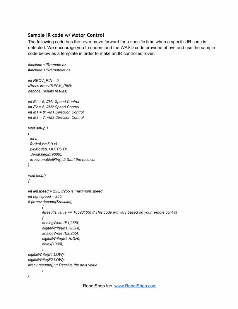
Sample IR code w/ Motor Control The following code has the rover move forward for a specific time when a specific IR code is detected. We encourage you to understand the WASD code provided above and use the sample code below as a template in order to make an IR controlled rover. #include <IRremote.h> #include <IRremoteInt.h> int RECV_PIN = 9; IRrecv irrecv(RECV_PIN); decode_results results; int E1 = 6; //M1 Speed Control int E2 = 5; //M2 Speed Control int M1 = 8; //M1 Direction Control int M2 = 7; //M2 Direction Control void setup() int i; for(i=5;i<=8;i++) pinMode(i, OUTPUT); Serial.begin(9600); irrecv.enableIRIn(); // Start the receiver void loop() int leftspeed = 255; //255 is maximum speed int rightspeed = 255; if (irrecv.decode(&results))
if(results.value == 16593103) // This code will vary based on your remote control analogWrite (E1,255); digitalWrite(M1,HIGH); analogWrite (E2,255); digitalWrite(M2,HIGH);
delay(1000); digitalWrite(E1,LOW); digitalWrite(E2,LOW); irrecv.resume(); // Receive the next value
RobotShop Inc. www.RobotShop.com

HyperTerminal Control To access Hyperterminal in Windows XP / 2000: Start > All Programs > Accessories > Communications > HyperTerminal Windows 7 does not come with Hyperterminal as a standard feature, so you must find an alternative. Note that hypertrm.exe is available online and emulates Hyperterminal.
RobotShop Inc. www.RobotShop.com

The name “DFRobotShop Rover is not necessary; you can name it whatever you want. Specify the COM port (USB) that is connected to the DFRobotShop Rover. If you are using XBee, Bluetooth or RF, select the COM port connected to the Bluetooth dongle / XBee breakout / RF Transmitter (USB). No configuration is needed for the DFRobot Bluetooth Module – simply connect to it in your Bluetooth application and the module installed on the DFRobotShop Rover will be picked up (assuming it is powered). To use the XBee modules, install one on the USB to XBee breakout board in the same orientation as indicated on the board, and connect the board via USB to your computer. The board should be picked up as a standard COM port. Install the other XBee module on the XBee shield and install the shield on the board ensuring the Tx/Rx pins of the shield line up with Rx/Tx pins on the DFRobotShop PCB. More information about the XBee shield can be found on www.arduino.cc.
RobotShop Inc. www.RobotShop.com
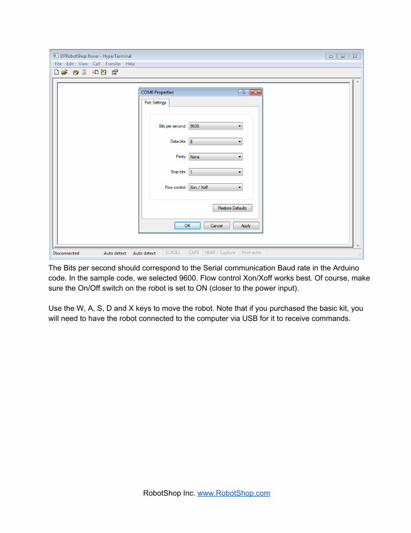
The Bits per second should correspond to the Serial communication Baud rate in the Arduino code. In the sample code, we selected 9600. Flow control Xon/Xoff works best. Of course, make sure the On/Off switch on the robot is set to ON (closer to the power input). Use the W, A, S, D and X keys to move the robot. Note that if you purchased the basic kit, you will need to have the robot connected to the computer via USB for it to receive commands.
RobotShop Inc. www.RobotShop.com