rough terrain crane boom lengths: 35 to 110 ft terrain crane 50 tons link-belt hsp-8050 boom...
TRANSCRIPT
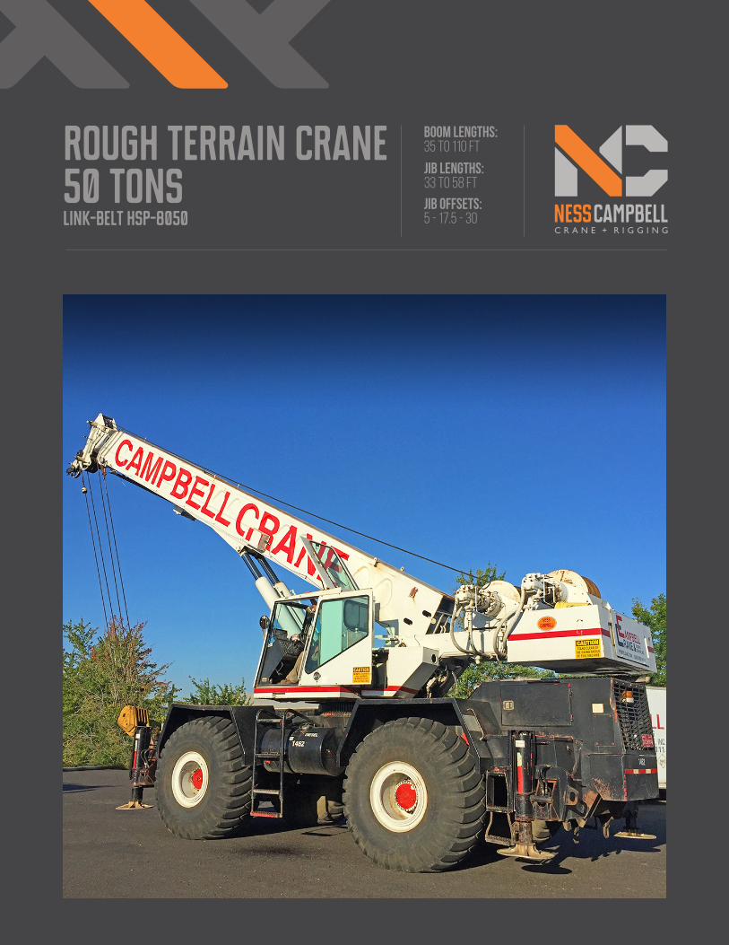
rough Terrain crane50 tonslink-belt hsp-8050
BOOM LENGTHS:35 to 110 ft
JIB LENGTHS:33 to 58 ft
JIB OFFSETS:5 - 17.5 - 30

NOTES:
portland office: 503.283.3111seattle office: 206.784.1054
www.nesscampbell.com
This information is for reference use only. operators manuals should be consulted and adhered to. please contact ness campbell at [email protected] for further information.
portland office: 503.283.3111seattle office: 206.784.1054
www.nesscampbell.com
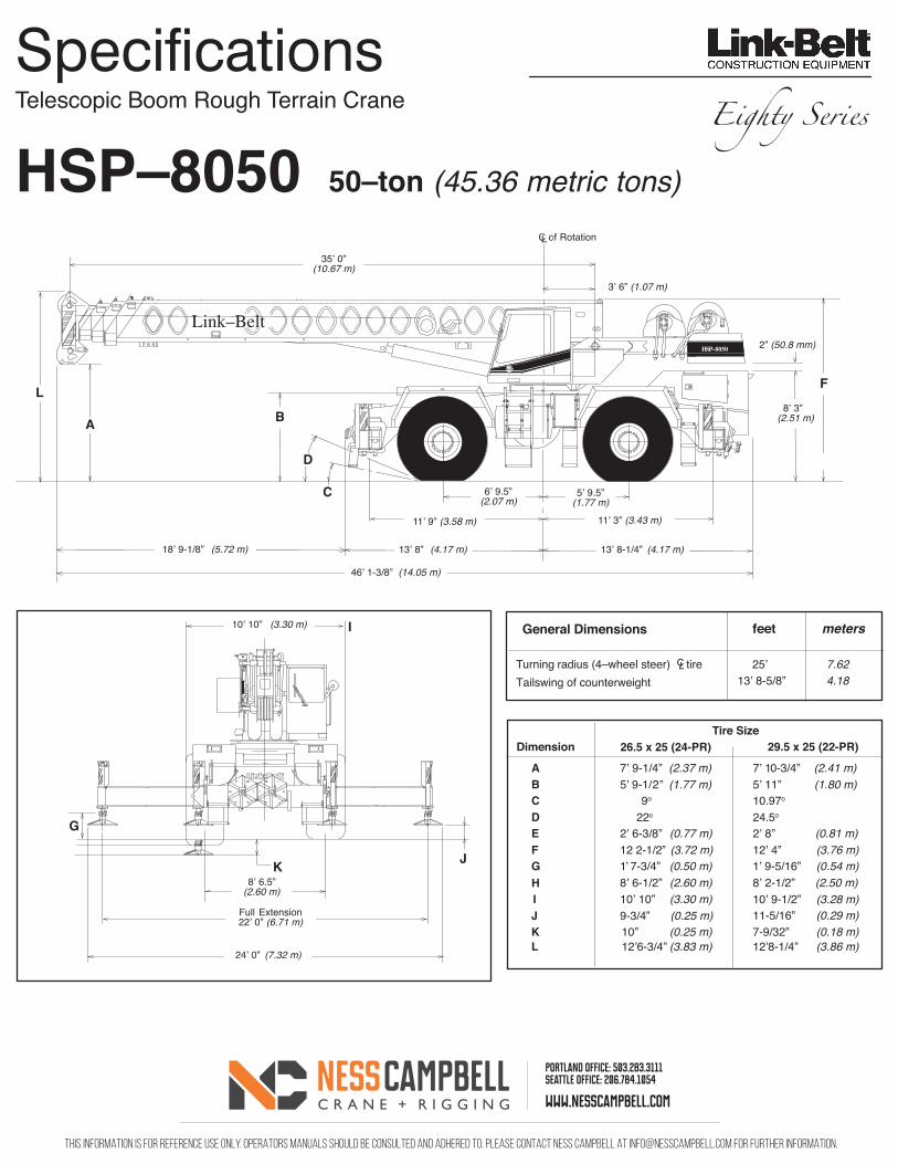
Telescopic Boom Rough Terrain Crane
HSP–8050 50–ton (45.36 metric tons)
G
K
Turning radius (4–wheel steer) tire 25’ 7.62Tailswing of counterweight
General Dimensions feet meters
46ʼ 1-3/8” (14.05 m)
35ʼ 0”(10.67 m)
3ʼ 6” (1.07 m)
C 6ʼ 9.5”(2.07 m)
11ʼ 9” (3.58 m) 11ʼ 3” (3.43 m)
13ʼ 8” (4.17 m)
8ʼ 6.5”(2.60 m)
D
C of RotationL
2” (50.8 mm)
L
A B
F
10ʼ 10” (3.30 m)
J
Tire SizeDimension 29.5 x 25 (22-PR)
A 7ʼ 9-1/4” (2.37 m) 7ʼ 10-3/4” (2.41 m)B 5ʼ 9-1/ 2” (1.77 m) 5ʼ 11” (1.80 m)C 9o 10.97o D 22o 24.5o E 2’ 6-3/8” (0.77 m) 2’ 8” (0.81 m)F 12 2-1/2” (3.72 m) 12’ 4” (3.76 m)G 1’ 7-3/4” (0.50 m) 1’ 9-5/16” (0.54 m)
8ʼ 3”(2.51 m)
5ʼ 9.5”(1.77 m)
Full Extension22ʼ 0” (6.71 m)
HSP–8050
Link–Belt
18ʼ 9-1/8” (5.72 m) 13ʼ 8-1/4” (4.17 m)
I
24ʼ 0” (7.32 m)
HIJK
10’ 10” (3.30 m)9-3/4” (0.25 m)10 ” (0.25 m)
8’ 6-1/2” (2.60 m)
13’ 8-5/8” 4.18
8’ 2-1/2” (2.50 m)10’ 9-1/2” (3.28 m)11-5/16” (0.29 m)7-9/32” (0.18 m)
26.5 x 25 (24-PR)
CL
Eighty Series
L 12’6-3/4” (3.83 m) 12’8-1/4” (3.86 m)

This information is for reference use only. operators manuals should be consulted and adhered to. please contact ness campbell at [email protected] for further information.
portland office: 503.283.3111seattle office: 206.784.1054
www.nesscampbell.com
UPPERSTRUCTURE LINK-BELT HSP-8050BOOM -Patent design. Boom side plates have diamond shaped impressions for superior strength to weight ratio and 100,000 psi (689.5 MPa) steel angle chord for lateral stiffness. Boom sections are supported by wear shoes both vertically and horizontally. Anti-two block, electronic boom length / angle indicator and function kickout.
Load Moment Indicator. Audio-visual warning system with anti-two block and function kickouts. Constant display of boom length and angle, tip height, radius of load, machine configuration, allowed load, actual load and % of allowed load. Presettable alarms for maximum and minimum boom angles, maximum tip height and maximum boom length.
Standard Boom. 35' 0" - 85' 0" (10.67m - 25.91m) 3-section full power boom.
Optional Boom. 35' 0" - 110' 0" (10.67m - 33.53m) 4-section boom includes base section, two power sections, and manual fourth section. Fourth section is power pinned by mannualy activating a cylinder locking system.
Boom Head - Standard. Four 16-3/8" (0.42m) root diameter head sheaves with five 16-3/8" (0.42m) available to handle up to 10 parts of wire rope. Two easily removable wire rope guards; rope dead end lugs provided on each side of boom head.
Auxiliary Lifting Sheave. Optional; single 16-3/8" (0.42m) root diameter head sheave with removable wire rope guard, mounted to boom, for use with one or two parts of line off the optional auxiliary winch. Does not affect erection of fly or jib, or use of main head sheave for multiple reeving.
Boom Elevation. Two hydraulic cylinders with holding valves. Self aligning steel bushings. Hand and optional foot controls for controlling the boom elevation from -3° to 78°.
FLY -Optional - 33' 0" (10.06m) stowable one-piece lattice type.
JIB -Optional - 25' 0" (7.62m) stowable A-frame which can be offset 5°, 17.5°, and 30°. Attaches to fly only.
CAB AND CONTROLS -Environmental cab; isolated from sound and vibration by a neoprene seal. All windows are tinted and tempered safety glass. Sliding rear and right side windows and swing up roof window for maximum visibility and ventilation. Slide-by-door opens to 3' 0" (0.91m) width. 6-way adjustable operator's seat. 4-way adjustable tilt/telescoping steering wheel. Control levers for swing, boom telescope, winch and boom hoist with foot control swing brake. Outrigger controls, sight level bubble. Optional foot control for boom hoist.
Cab Instrumentation. Dash mounted gauges for hydraulic oil temperature, converter temperature, oil pressure, water pressure, fuel and volt-meter.
SWING -Bi-directional hydraulic swing motor mounted to a planetary reducer for 360° continuous smooth swing at 2.45 r.p.m.
Swing Brake - Standard. Foot operated; spring released disc brake mountd on the speed reducer.
Swing Lock - Standard. 360° position pin type and two position travel lock operated from the operator's cab.
Counterweight. Pinned to upperstructure frame.
HYDRAULIC SYSTEM -Main Pump. Triple gear-type pump. Combined pump capacity 161 gpm (609.4 lpm). Powered by torque converter through a pump disconnect. Pump disconnect is a jaw-type clutch engaged/disengagged from carrier. Maximum system pressure at 2900 p.s.i. (199.94 bars).
Steering/Outrigger Pump. Single gear-type pump, 28 gpm (106 lpm) maximum. Powered by torque converter through a straight mechanical drive. Pump operates at 2700 p.s.i. (186.25 bars).
Reservoir. 140 gallon (530.0 L) capacity. Diffusers for deareation.
Filtration. One six-micron filter located inside the hydraulic reservoir. Accessible for easy replacement.
Control Valves. Six separate control valves allow simultaneous operation of all crane functions.
LOAD HOIST SYSTEM -Standard. Model 2M main winch with two-speed motor and automatic brake; power up/power down mode of operation. Bi-directional gear type hydraulic motor.
Optional. Model 2M auxiliary winch with two-speed motor and automatic brake, power up/power down mode of operation. Bi-directional, gear-type hydraulic motor.
Optional. Model 3M winch with power up/power down, two-speed motor and exclusive controlled true gravity free fall. Available on main winch only.
Line Pulls and Speeds. Maximum line pull 15,870 lbs. (7,199 kg) and maximum line speed 548 f.p.m. (167.03 m/min.) on 17" (0.43 m) root diameter smooth drum.
ADDITIONAL EQUIPMENT -Standard. Rear view mirrors, seatbelt, fire extinguisher, backup alarm, travel lights and sound suppressed cab.
ADDITIONAL UPPERSTRUCTURE EQUIPMENT -Optional. Propane heater, diesel heater, air conditioning, drum rotation indicators, 60-ton (54.43 metric ton) hook block, 8-1/2 ton (7.71 metric ton) hook ball and swivel, rear steer indicator, boom mounted working light, engine monitoring system, top hatch wiper, windshield washer, hand throttle, lifting lugs, tachometer, amber rotating beacon, cab spotlight and boomhoist foot control.
This information is for reference use only. operators manuals should be consulted and adhered to. please contact ness campbell at [email protected] for further information.
portland office: 503.283.3111seattle office: 206.784.1054
www.nesscampbell.com
CARRIER LINK-BELT HSP-8050TYPE -10' 10" (3.30 m) wide, 151" (3.84 m) wheelbase.
4x4x4 (4-wheel steer, 4-wheel drive) Standard; for rough terrain with limited turning area.
4x4x4 (4-wheel steer, 4-wheel drive) Optional; no spin differential on front axle; for rough terrain with limited turning area.
Frame. 100,000 p.s.i. (689.5 MPa) steel, double walled construction with integral 100,000 p.s.i. (689.5 MPa) steel outrigger boxes.
AXLES -Front Standard. Heavy duty planetary drive/steer type.
Rear Standard. Heavy duty planetary drive/steer type.
Front Optional. Heavy duty no-spin high traction differential, planetary drive/steer type.
SUSPENSION -Front Axle. Rigid mounted to frame.
Rear Axle. Pin-mounted on bronze bushings, automatic hydraulic rear axle oscillation lock-out cylinders engage when upperstructure rotates past 2-1/2° of centerline.
TIRES -Front and Rear Standard. 26.5 x 25 (24-PR Earthmover type).
Optional. 29.5 x 25 (22-PR Earthmover type).
BRAKES -Service. Air over hydraulic, drum-type brakes at each wheel end. Drum diameter 20-1/4" (0.51 m). Shoe width 4" (101.6 mm).
Parking/Emergency. Disc caliper type spring applied, air released, fade resistant; cab controlled, mounted on front axle.
STEERING -Hydraulic two wheel, four wheel and "crab" steering.
TRANSMISSION -3-speed, 2-range power shift transmission. Six speeds available forward and 2 reverse. Front axle disconnect for two or four-wheel drive.
OUTRIGGERS -Four hydraulic, beam and jack outriggers. Vertical jack cylinders equipped with integral holding valve. Beams extend to 22'0" (6.71 m) centerline-to-centerline and retract wo within 10' 10" (3.30 m) overall width with floats stored. Equipped with stowable, lightweight 24" (0.61 m) diameter floats. Controls and sight level bubble located in upperstructure cab.
ADDITIONAL EQUIPMENT -Standard. Cab steps, 2 front carrier steps, skid resistant finish on carrier deck, storage compartment and fenders.
Optional. Towing shackles, ether injection, no-spin differential on front axle, spare tires and rims, pintle hook, jack cylinder hose covers, propane fired engine block heater, air dryer and emergency steering system.
This information is for reference use only. operators manuals should be consulted and adhered to. please contact ness campbell at [email protected] for further information.
portland office: 503.283.3111seattle office: 206.784.1054
www.nesscampbell.com
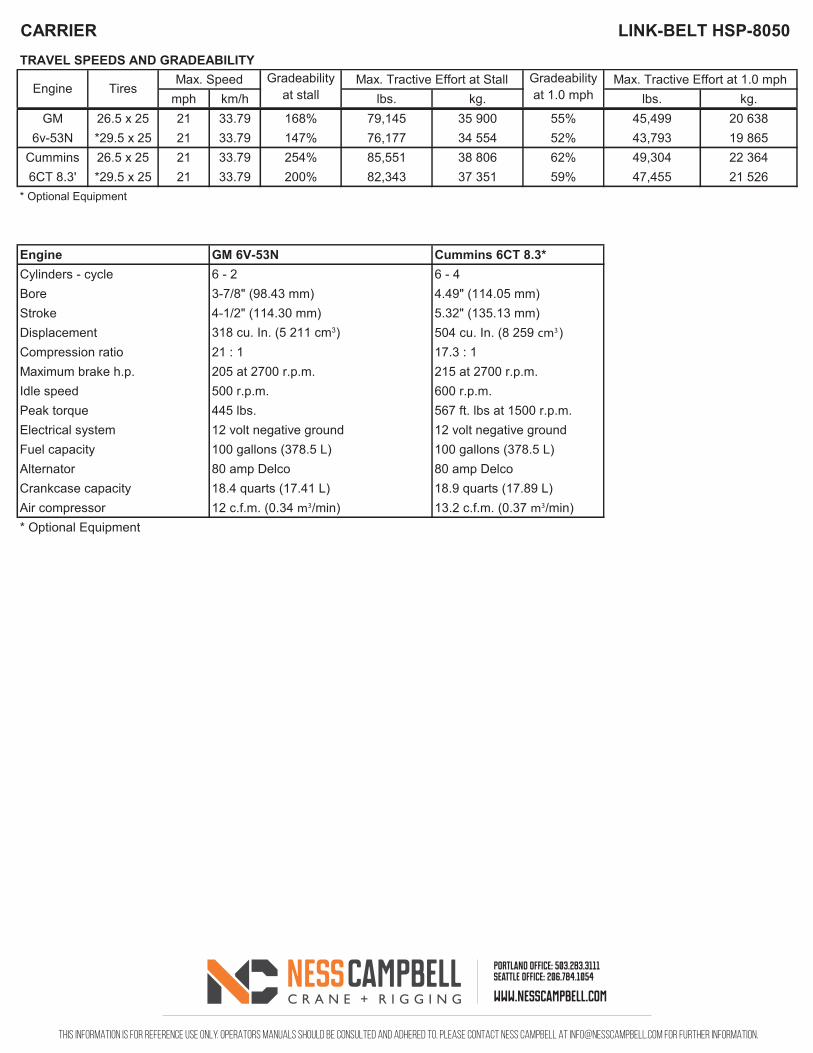
Gradeability Gradeabilitymph km/h at stall lbs. kg. at 1.0 mph lbs. kg.
GM 26.5 x 25 21 33.79 168% 79,145 35 900 55% 45,499 20 6386v-53N *29.5 x 25 21 33.79 147% 76,177 34 554 52% 43,793 19 865
Cummins 26.5 x 25 21 33.79 254% 85,551 38 806 62% 49,304 22 3646CT 8.3' *29.5 x 25 21 33.79 200% 82,343 37 351 59% 47,455 21 526
* Optional Equipment
Engine GM 6V-53N Cummins 6CT 8.3*Cylinders - cycle 6 - 2 6 - 4Bore 3-7/8" (98.43 mm) 4.49" (114.05 mm)Stroke 4-1/2" (114.30 mm) 5.32" (135.13 mm)Displacement 318 cu. In. (5 211 cm3) 504 cu. In. (8 259 cm3)Compression ratio 21 : 1 17.3 : 1Maximum brake h.p. 205 at 2700 r.p.m. 215 at 2700 r.p.m.Idle speed 500 r.p.m. 600 r.p.m.Peak torque 445 lbs. 567 ft. lbs at 1500 r.p.m.Electrical system 12 volt negative ground 12 volt negative groundFuel capacity 100 gallons (378.5 L) 100 gallons (378.5 L)Alternator 80 amp Delco 80 amp DelcoCrankcase capacity 18.4 quarts (17.41 L) 18.9 quarts (17.89 L)Air compressor 12 c.f.m. (0.34 m3/min) 13.2 c.f.m. (0.37 m3/min)* Optional Equipment
Max. Tractive Effort at 1.0 mphTRAVEL SPEEDS AND GRADEABILITY
CARRIER LINK-BELT HSP-8050
Max. Speed Max. Tractive Effort at StallEngine Tires
This information is for reference use only. operators manuals should be consulted and adhered to. please contact ness campbell at [email protected] for further information.
portland office: 503.283.3111seattle office: 206.784.1054
www.nesscampbell.com
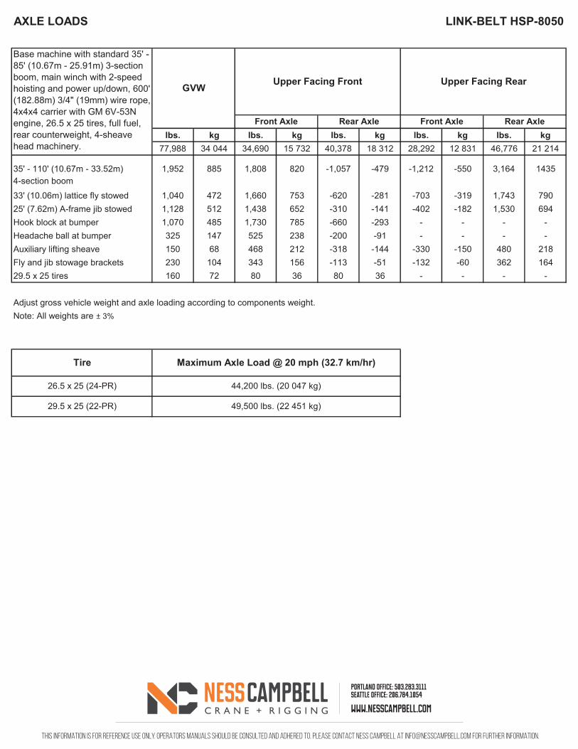
lbs. kg lbs. kg lbs. kg lbs. kg lbs. kg77,988 34 044 34,690 15 732 40,378 18 312 28,292 12 831 46,776 21 214
35' - 110' (10.67m - 33.52m) 1,952 885 1,808 820 -1,057 -479 -1,212 -550 3,164 14354-section boom
33' (10.06m) lattice fly stowed 1,040 472 1,660 753 -620 -281 -703 -319 1,743 79025' (7.62m) A-frame jib stowed 1,128 512 1,438 652 -310 -141 -402 -182 1,530 694Hook block at bumper 1,070 485 1,730 785 -660 -293 - - - -Headache ball at bumper 325 147 525 238 -200 -91 - - - -Auxiliary lifting sheave 150 68 468 212 -318 -144 -330 -150 480 218Fly and jib stowage brackets 230 104 343 156 -113 -51 -132 -60 362 16429.5 x 25 tires 160 72 80 36 80 36 - - - -
Adjust gross vehicle weight and axle loading according to components weight.Note: All weights are ± 3%
Tire Maximum Axle Load @ 20 mph (32.7 km/hr)
26.5 x 25 (24-PR)
29.5 x 25 (22-PR)
44,200 lbs. (20 047 kg)
49,500 lbs. (22 451 kg)
Base machine with standard 35' - 85' (10.67m - 25.91m) 3-section boom, main winch with 2-speed hoisting and power up/down, 600' (182.88m) 3/4" (19mm) wire rope, 4x4x4 carrier with GM 6V-53N engine, 26.5 x 25 tires, full fuel, rear counterweight, 4-sheave head machinery.
GVW
Front Axle Rear Axle Front Axle Rear Axle
Upper Facing Front Upper Facing Rear
LINK-BELT HSP-8050AXLE LOADS
This information is for reference use only. operators manuals should be consulted and adhered to. please contact ness campbell at [email protected] for further information.
portland office: 503.283.3111seattle office: 206.784.1054
www.nesscampbell.com
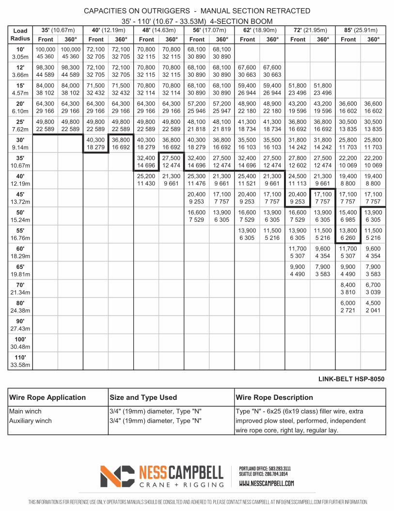
Front 360° Front 360° Front 360° Front 360° Front 360° Front 360° Front 360°10'
3.05m100,00045 360
100,00045 360
72,10032 705
72,10032 705
70,80032 115
70,80032 115
68,10030 890
68,10030 890
12'3.66m
98,30044 589
98,30044 589
72,10032 705
72,10032 705
70,80032 115
70,80032 115
68,10030 890
68,10030 890
67,60030 663
67,60030 663
15'4.57m
84,00038 102
84,00038 102
71,50032 432
71,50032 432
70,80032 114
70,80032 114
68,10030 890
68,10030 890
59,40026 944
59,40026 944
51,80023 496
51,80023 496
20'6.10m
64,30029 166
64,30029 166
64,30029 166
64,30029 166
64,30029 166
64,30029 166
57,20025 946
57,20025 947
48,90022 180
48,90022 180
43,20019 596
43,20019 596
36,60016 602
36,60016 602
25'7.62m
49,80022 589
49,80022 589
49,80022 589
49,80022 589
49,80022 589
49,80022 589
48,10021 818
48,10021 819
41,30018 734
41,30018 734
36,80016 692
36,80016 692
30,50013 835
30,50013 835
30'9.14m
40,30018 279
36,80016 692
40,30018 279
36,80016 692
40,30018 279
36,80016 692
35,50016 103
35,50016 103
31,80014 242
31,80014 242
25,80011 703
25,80011 703
35'10.67m
32,40014 696
27,50012 474
32,40014 696
27,50012 474
32,40014 696
27,50012 474
27,80012 602
27,50012 474
22,20010 069
22,20010 069
40'12.19m
25,20011 430
21,3009 661
25,30011 476
21,3009 661
25,40011 521
21,3009 661
24,50011 113
21,3009 661
19,4008 800
19,4008 800
45'13.72m
20,4009 253
17,1007 757
20,4009 253
17,1007 757
20,4009 253
17,1007 757
17,1007 757
17,1007 757
50'15.24m
16,6007 529
13,9006 305
16,6007 529
13,9006 305
16,6007 529
13,9006 305
15,4006 985
13,9006 305
55'16.76m
13,9006 305
11,5005 216
13,9006 305
11,5005 216
13,8006 260
11,5005 216
60'18.29m
11,7005 307
9,6004 354
11,7005 307
9,6004 354
65'19.81m
9,9004 490
7,9003 583
9,9004 490
7,9003 583
70'21.34m
8,4003 810
6,7003 039
80'24.38m
6,0002 721
4,5002 041
90'27.43m
100'30.48m
110'33.58m
Wire Rope Application Size and Type Used Wire Rope Description
Main winch 3/4" (19mm) diameter, Type "N" Type "N" - 6x25 (6x19 class) filler wire, extraAuxiliary winch 3/4" (19mm) diameter, Type "N" improved plow steel, performed, independent
wire rope core, right lay, regular lay.
72' (21.95m) 85' (25.91m)
CAPACITIES ON OUTRIGGERS - MANUAL SECTION RETRACTED35' - 110' (10.67 - 33.53M) 4-SECTION BOOM
Load Radius
35' (10.67m) 40' (12.19m) 48' (14.63m) 56' (17.07m) 62' (18.90m)
LINK-BELT HSP-8050
This information is for reference use only. operators manuals should be consulted and adhered to. please contact ness campbell at [email protected] for further information.
portland office: 503.283.3111seattle office: 206.784.1054
www.nesscampbell.com
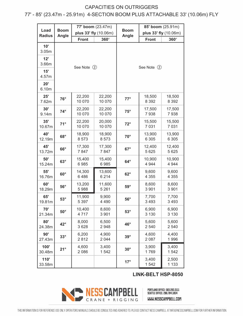
Front 360° Front 360°10'
3.05m
12'3.66m
15'4.57m
20'6.10m
25'7.62m 76° 22,200
10 07022,20010 070 77° 18,500
8 39218,5008 392
30'9.14m 74° 22,200
10 07022,20010 070 75° 17,500
7 93817,5007 938
35'10.67m 71° 22,200
10 07020,00010 070 72° 15,500
7 03115,5007 031
40'12.19m 68° 18,900
8 57318,9008 573 70° 13,900
6 30513,9006 305
45'13.72m 66° 17,300
7 84717,3007 847 67° 12,400
5 62512,4005 625
50'15.24m 63° 15,400
6 98515,4006 985 64° 10,900
4 94410,9004 944
55'16.76m 60° 14,300
6 48613,6006 214 62° 9,600
4 3559,6004 355
60'18.29m 56° 13,200
5 98811,6005 261 59° 8,600
3 9018,6003 901
65'19.81m 53° 11,900
5 3979,9004 490 56° 7,700
3 4937,7003 493
70'21.34m 50° 10,400
4 7178,6003 901 53° 6,900
3 1306,9003 130
80'24.38m 42° 8,000
3 6286,5002 948 46° 5,600
2 5405,6002 540
90'27.43m 33° 6,200
2 8124,9002 044 39° 4,600
2 0874,4001 996
100'30.48m 21° 4,600
2 0863,4001 542 30° 3,900
1 7693,4001 542
110'33.58m 17° 3,400
1 5422,5001 133
LINK-BELT HSP-8050
CAPACITIES ON OUTRIGGERS77' - 85' (23.47m - 25.91m) 4-SECTION BOOM PLUS ATTACHABLE 33' (10.06m) FLY
77' boom (23.47m) 85' boom (25.91m)Boom Angle
Boom Angle
See Note ② See Note ②
Load Radius plus 33' fly (10.06m) plus 33' fly (10.06m)
This information is for reference use only. operators manuals should be consulted and adhered to. please contact ness campbell at [email protected] for further information.
portland office: 503.283.3111seattle office: 206.784.1054
www.nesscampbell.com
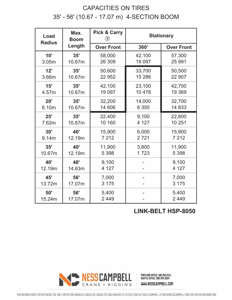
Over Front 360° Over Front10'
3.05m35'
10.67m58,00026 309
42,10019 097
57,30025 991
12'3.66m
35'10.67m
50,60022 952
33,70015 286
50,50022 907
15'4.57m
35'10.67m
42,10019 097
23,10010 478
42,70019 369
20'6.10m
35'10.67m
32,20014 606
14,0006 350
32,70014 833
25'7.62m
35'10.67m
22,40010 160
9,1004 127
22,60010 251
30'9.14m
40'12.19m
15,9007 212
6,0002 721
15,9007 212
35'10.67m
40'12.19m
11,9005 398
3,8001 723
11,9005 398
40'12.19m
48'14.63m
9,1004 127
--
9,1004 127
45'13.72m
56'17.07m
7,0003 175
--
7,0003 175
50'15.24m
56'17.07m
5,4002 449
--
5,4002 449
LINK-BELT HSP-8050
Load Radius
Pick & Carry ③ StationaryMax.
Boom Length
CAPACITIES ON TIRES35' - 56' (10.67 - 17.07 m) 4-SECTION BOOM