rotordynamic performance of a flexure pivot pad …
TRANSCRIPT
ROTORDYNAMIC PERFORMANCE OF A FLEXURE PIVOT PAD BEARING
WITH ACTIVE AND LOCKED INTEGRAL SQUEEZE FILM DAMPER
INCLUDING PREDICTIONS
A Thesis
by
JEFFREY SCOTT AGNEW
Submitted to the Office of Graduate Studies of
Texas A&M University
in partial fulfillment of the requirements for the degree of
MASTER OF SCIENCE
December 2011
Major Subject: Mechanical Engineering
Rotordynamic Performance of a Flexure Pivot Pad Bearing with Active and Locked
Integral Squeeze Film Damper Including Predictions
Copyright 2011 Jeffrey Scott Agnew
ROTORDYNAMIC PERFORMANCE OF A FLEXURE PIVOT PAD BEARING
WITH ACTIVE AND LOCKED INTEGRAL SQUEEZE FILM DAMPER
INCLUDING PREDICTIONS
A Thesis
by
JEFFREY SCOTT AGNEW
Submitted to the Office of Graduate Studies of
Texas A&M University
in partial fulfillment of the requirements for the degree of
MASTER OF SCIENCE
Approved by:
Chair of Committee, Dara W. Childs
Committee Members, William H. Marlow
Luis A. San Andrés
Head of Department, Jerry Caton
December 2011
Major Subject: Mechanical Engineering

iii
ABSTRACT
Rotordynamic Performance of a Flexure Pivot Pad Bearing with Active and Locked
Integral Squeeze Film Damper Including Predictions. (December 2011)
Jeffrey Scott Agnew, B.S., Arkansas State University
Chair of Advisory Committee: Dr. Dara W. Childs
Tests are performed on a flexure-pivot-pad tilting-pad bearing with a series
integral squeeze film damper in load-between-pads configuration, with both active and
locked damper. The damper effects are negated when locked, resulting in a flexure-
pivot-pad bearing only. Experimental tests provide static performance data and dynamic
stiffnesses from which rotordynamic coefficients are extracted. The following two
excitation schemes are implemented: (1) multi-frequency, single direction excitation and
(2) single-frequency, rotating load excitation (or “circular excitation”). The XLTRC2
Rotordynamics Software Suite© provides stiffness and damping coefficient, eccentricity,
and power loss predictions for the locked damper bearing. Test conditions include the
rotor-speed range of 4000-12000 rpm and the unit-load range of 0-862 kPa (0-125 psi).
Dynamic tests utilizing the multi-frequency excitation for the locked and active
damper bearing configurations both show that the real portion of the dynamic stiffness is
well modeled by a quadratic curve fit, and the imaginary portion representing the
damping is a linear function of excitation frequency. This means that frequency
independent coefficients can be obtained when an added mass term is included. While

iv
stiffness coefficients are lower for the active damper bearing, damping coefficients
remain almost constant between the locked and active damper configurations. A
simulation shows that, although the damping coefficients do not change significantly, the
reduced stiffness provided by the damper results in greater effective damping.
Static performance tests for the locked and active damper bearing indicate low
cross-coupling, as shown by the eccentricity and low attitude angle measurements. Pad
metal temperature measurements show a smaller temperature differential along the pad
arcs for the active damper bearing, than observed for the locked damper case. Frictional
power loss is estimated based on lubricant temperature rise and does not differ
significantly for the two bearing configurations.

v
ACKNOWLEDGEMENTS
My sincere gratitude goes to all of the members on my thesis committee,
including Dara Childs, Luis San Andrès, and William Marlow. Since Dr. Childs offered
me a research position at the Texas A&M Turbomachinery Lab, he has been a persistent,
but patient, advocate of this thesis and without his guidance and support this thesis
would not have been possible. Dr. San Andrès provided practical advice and a helping
hand on numerous occasions. All of my professors during both my undergraduate and
graduate educations helped to further my interests and skills in engineering and science,
to all of whom I am appreciative.
Bearings Plus, Incorporated (BPI) graciously supplied the test bearing, and
thanks to Dr. Fouad Zeidan and Dr. Jongsoo Kim of BPI for their support of this project.
Also, thanks to the Turbomachinery Research Consortium (TRC) for their funding.
Additional gratitude goes to my coworkers at the Turbomachinery Lab, namely
Robert Sheets and Andy Schaible, who both helped tremendously in the testing phase
and who traded many of their days and late nights for lending me a hand. Jason Wilkes
was also invaluable and provided consultation relating to the rotating load section of this
thesis. Steve Phillips provided technical assistance on various aspects of the project.
Finally, my wife Erin provided continual support and understanding throughout
my career as a graduate student. I thank and love her for this.
vi
TABLE OF CONTENTS
Page
ABSTRACT ...................................................................................................................... iii
ACKNOWLEDGEMENTS ............................................................................................... v
TABLE OF CONTENTS .................................................................................................. vi
LIST OF FIGURES........................................................................................................... ix
LIST OF TABLES ........................................................................................................... xii
NOMENCLATURE ....................................................................................................... xvii
1. INTRODUCTION.......................................................................................................... 1
Bearing concepts and background ................................................................................. 4
Test Bearing: Flexure-Pivot-Pad Bearing with Integral Squeeze Film Damper .......... 11
Objectives ..................................................................................................................... 12
2. TEST RIG DESCRIPTION ......................................................................................... 14
Main Test Rig ............................................................................................................... 14
Static and Dynamic Loading ........................................................................................ 16
Instrumentation ............................................................................................................ 19
3. PRELIMINARY TESTING AND RESULTS ............................................................. 20
Bearing Pad Rotational Stiffness and Damping ........................................................... 20
Beam Theory Pad Stiffness ...................................................................................... 20
Experimental Pad Stiffness and Damping ................................................................ 22
Squeeze Film Damper Structural Stiffness .................................................................. 25
Measured of Damper Stiffness ................................................................................. 25
Predicted Damper Stiffness ...................................................................................... 27
4. EXPERIMENTAL PROCEDURES AND PARAMETER IDENTIFICATION ........ 30
Centering the Bearing .................................................................................................. 31
Static Load Test Procedure .......................................................................................... 32
Static Load Parameter Identification ............................................................................ 34
Eccentricity Ratio and Attitude Angle ..................................................................... 34
Temperature Dependent Lubricant Properties ......................................................... 35
vii
Page
Power Loss ............................................................................................................... 35
Sommerfeld Number ................................................................................................ 36
Dynamic Load Test Procedure ..................................................................................... 37
Rotordynamic Parameter Identification ....................................................................... 38
Curve Fitting and Uncertainty Analysis ................................................................... 39
Non-Dimensionalization of Rotordynamic Coefficients .......................................... 42
Whirl Frequency Ratio ............................................................................................. 43
5. ANALYTICAL PROCEDURE ................................................................................... 45
XLTRC2-XLTFPBrg Rotordynamics Suite© .............................................................. 45
XLTRC2-XLTFPBrg Modeling Options ..................................................................... 46
Pad Inertia, Rotational Stiffness, and Damping ....................................................... 46
Fluid Inertia .............................................................................................................. 46
Thermal Analysis ..................................................................................................... 47
Oil-Mixing Parameter ............................................................................................... 47
XLTFPBrg Chosen Input Parameters .......................................................................... 47
Prediction Post Processing ........................................................................................... 50
6. STATIC RESULTS: MEASURED AND PREDICTED ............................................. 52
Eccentricity and Attitude Angle ................................................................................... 52
Pad Metal and Squeeze Film Land Metal Temperatures ............................................. 58
Estimated Power Loss .................................................................................................. 64
7. MEASURED AND PREDICTED MULTI-FREQUENCY RESULTS ...................... 66
Baseline Data ............................................................................................................... 66
Dynamic Stiffnesses ..................................................................................................... 69
Rotordynamic Coefficients .......................................................................................... 73
Measurements and Predictions ................................................................................. 73
Effect of Integral Squeeze Film Damper on Rotordynamic Coefficients ................ 78
Similar FPJB Non-Dimensionalized Results Comparison ........................................... 82
Whirl Frequency Ratio (WFR) .................................................................................... 84
8. ROTATING LOAD TEST RESULTS ........................................................................ 87
9. CONCLUSIONS .......................................................................................................... 96
REFERENCES ............................................................................................................... 100
APPENDIX .................................................................................................................... 103

viii
Page
VITA .............................................................................................................................. 178
ix
LIST OF FIGURES
Page
Figure 1. Rocker pivot and spherical pivot pad bearings ................................................... 2
Figure 2. Flexure-pivot-pad bearing ................................................................................... 2
Figure 3. Conventional squeeze film damper with centering spring .................................. 3
Figure 4. Flexure pivot pad bearing with integral squeeze film damper
with seal removed for clarity and with seal installed ....................................... 3
Figure 5. Simplified squeeze film damper ......................................................................... 7
Figure 6. Bearing test rig main sectional .......................................................................... 15
Figure 7. Static loader as viewed from the NDE .............................................................. 17
Figure 8. Stator-shaker arrangement viewed from the non-drive end .............................. 18
Figure 9. Cantilever beam model of pad web .................................................................. 21
Figure 10. Accelerometer location on bearing pad .......................................................... 23
Figure 11. Typical dry bearing pad response to an impact .............................................. 23
Figure 12. Loaded pads shimmed for damper stiffness measurements ............................ 25
Figure 13. Experimental load versus displacement for squeeze film damper .................. 26
Figure 14. Restraint and load locations for FEA damper analysis ................................... 28
Figure 15. Exaggerated scale damper deformation for 0.4 kN load ................................ 28
Figure 16. Predicted damper stiffness results using FEA ................................................ 29
Figure 17. Damper is locked using pins ........................................................................... 30
Figure 18. Process for finding bearing center .................................................................. 31
Figure 19. Eccentricity and attitude angle ........................................................................ 34
Figure 20. Coefficients extraction from dynamic stiffness .............................................. 41
Figure 21. Input parameters for XLTFPBrg used to model FPJB ................................... 49
x
Page
Figure 22. Output screen for FPJB using XLTFPBrg ...................................................... 50
Figure 23. Experimental and analytical coordinate systems ............................................ 51
Figure 24. Experimental and predicted loci plots for all test conditions .......................... 55
Figure 25. Experimental and predicted eccentricity ratio and attitude angle
versus load at a shaft speed of 12000 rpm ..................................................... 56
Figure 26. Experimental and predicted eccentricity ratio and attitude angle
versus shaft speed at a sample load of 689 kPa .............................................. 57
Figure 27. Bearing and squeeze film land thermocouple locations ................................. 59
Figure 28. Squeeze film land thermocouple DE and NDE locations ............................... 59
Figure 29. Measured pad metal temperatures and corresponding oil supply
temperatures for both bearing configurations at 4000 rpm ............................ 61
Figure 30. Measured pad metal temperatures and corresponding oil supply
temperatures for both bearing configurations at 517 kPa............................... 62
Figure 31. Damper bearing squeeze film land temperatures at 4000 rpm
and 517 kPa .................................................................................................... 63
Figure 32. Experimental and predicted power loss for different shaft
speeds and static loads .................................................................................... 65
Figure 33. Baseline real dynamic stiffnesses for FPJB and damper-bearing ................... 68
Figure 34. Baseline imaginary dynamic stiffnesses for FPJB and
damper-bearing ............................................................................................... 69
Figure 35. Real direct and cross-coupled dynamic stiffnesses at 4000 rpm
and 172 kPa .................................................................................................... 71
Figure 36. Imaginary direct and cross-coupled dynamic stiffnesses at
4000 rpm and 172 kPa .................................................................................... 72
Figure 37. Stiffness, Damping, and added mass coefficients for a sample
shaft speed of 8000 rpm for FPJB and damper-bearing ................................. 75
Figure 38. Stiffness, damping, and added mass coefficients for a sample
load of 517 kPa for FPJB and damper-bearing .............................................. 77

xi
Page
Figure 39. Effect of squeeze film damper on bearing coefficients at a static
load of 345 kPa ............................................................................................... 78
Figure 40. XLTRC2 rotor model ...................................................................................... 79
Figure 41. Mode shape for a shaft speed of 10000 rpm ................................................... 80
Figure 42. Simulated peak-to-peak response for FPJB and damper-bearing ................... 81
Figure 43. Non-dimensional rotordynamic coefficients versus Sommerfeld
number ............................................................................................................ 83
Figure 44. WFR at different static loads and shaft speeds ............................................... 85
Figure 45. Ideal rotating excitation force at sample amplitudes ...................................... 88
Figure 46. Raw and filtered signals at a sample excitation of 100 Hz
and 890 N ....................................................................................................... 90
Figure 47. Force frequency spectrum for x- and y-directions for 100 Hz
and 890 N sample excitation .......................................................................... 91
Figure 48. Filtered displacement orbits for multiple excitation forces at
100 Hz ............................................................................................................ 91
Figure 49. Stiffness, damping, and added mass coefficients at different
excitation amplitudes ...................................................................................... 95
xii
LIST OF TABLES
Page
Table 1. Test bearing parameters ..................................................................................... 12
Table 2. Test conditions for both locked and active damper configurations ................... 33
Table 3. FPJB measured loci data .................................................................................. 103
Table 4. Damper-bearing measured loci data ................................................................. 104
Table 5. FPJB temperature and power loss data ............................................................ 105
Table 6. Damper-bearing measured temperature and power loss data........................... 106
Table 7. FPJB measured pad metal temperatures .......................................................... 107
Table 8. Damper-bearing measured pad metal temperatures ......................................... 108
Table 9. Damper-bearing squeeze film land metal temperatures ................................... 109
Table 10. FPJB measured stiffness coefficients summary ............................................. 110
Table 11. FPJB measured damping coefficients summary ............................................ 111
Table 12. FPJB measured added mass coefficients summary ........................................ 112
Table 13. FPJB predicted static and dynamic data ......................................................... 113
Table 14. Damper-bearing measured stiffness coefficients summary ........................... 114
Table 15. Damper-bearing measured damping coefficients summary ........................... 115
Table 16. Damper-bearing measured added mass coefficients summary ...................... 116
Table 17. FPJB measured baseline dynamic stiffnesses for 0 rpm and 0 kPa ............... 117
Table 18. FPJB measured dynamic stiffnesses for 4000 rpm and 0 kPa ....................... 118
Table 19. FPJB measured dynamic stiffnesses for 4000 rpm and 172 kPa ................... 119
Table 20. FPJB measured dynamic stiffnesses for 4000 rpm and 345 kPa ................... 120
Table 21. FPJB measured dynamic stiffnesses for 4000 rpm and 517 kPa ................... 121
xiii
Page
Table 22. FPJB measured dynamic stiffnesses for 4000 rpm and 689 kPa ................... 122
Table 23. FPJB measured dynamic stiffnesses for 6000 rpm and 0 kPa ....................... 123
Table 24. FPJB measured dynamic stiffnesses for 6000 rpm and 172 kPa ................... 124
Table 25. FPJB measured dynamic stiffnesses for 6000 rpm and 345 kPa ................... 125
Table 26. FPJB measured dynamic stiffnesses for 6000 rpm and 517 kPa ................... 126
Table 27. FPJB measured dynamic stiffnesses for 6000 rpm and 689 kPa ................... 127
Table 28. FPJB measured dynamic stiffnesses for 6000 rpm and 862 kPa ................... 128
Table 29. FPJB measured dynamic stiffnesses for 8000 rpm and 0 kPa ....................... 129
Table 30. FPJB measured dynamic stiffnesses for 8000 rpm and 172 kPa ................... 130
Table 31. FPJB measured dynamic stiffnesses for 8000 rpm and 345 kPa ................... 131
Table 32. FPJB measured dynamic stiffnesses for 8000 rpm and 689 kPa ................... 132
Table 33. FPJB measured dynamic stiffnesses for 8000 rpm and 862 kPa ................... 133
Table 34. FPJB measured dynamic stiffnesses for 10000 rpm and 0 kPa ..................... 134
Table 35. FPJB measured dynamic stiffnesses for 10000 rpm and 172 kPa ................. 135
Table 36. FPJB measured dynamic stiffnesses for 10000 rpm and 345 kPa ................. 136
Table 37. FPJB measured dynamic stiffnesses for 10000 rpm and 517 kPa ................. 137
Table 38. FPJB measured dynamic stiffnesses for 10000 rpm and 689 kPa ................. 138
Table 39. FPJB measured dynamic stiffnesses for 10000 rpm and 862 kPa ................. 139
Table 40. FPJB measured dynamic stiffnesses for 12000 rpm and 0 kPa ..................... 140
Table 41. FPJB measured dynamic stiffnesses for 12000 rpm and 172 kPa ................. 141
Table 42. FPKB measured dynamic stiffnesses for 12000 rpm and 345 kPa ................ 142
Table 43. FPJB measured dynamic stiffnesses for 12000 rpm and 517 kPa ................. 143
Table 44. FPJB measured dynamic stiffnesses for 12000 rpm and 689 kPa ................. 144
xiv
Page
Table 45. FPJB measured dynamic stiffnesses for 12000 rpm and 862 kPa ................. 145
Table 46. Damper-bearing measured baseline dynamic stiffnesses for 0 rpm
and 0 kPa ........................................................................................................ 146
Table 47. Damper-bearing measured dynamic stiffnesses for 4000 rpm and
0 kPa .............................................................................................................. 147
Table 48. Damper-bearing measured dynamic stiffnesses for 4000 rpm and
172 kPa .......................................................................................................... 148
Table 49. Damper-bearing measured dynamic stiffnesses for 4000 rpm and
345 kPa .......................................................................................................... 149
Table 50. Damper-bearing measured dynamic stiffnesses for 4000 rpm and
517 kPa .......................................................................................................... 150
Table 51. Damper-bearing measured dynamic stiffnesses for 4000 rpm and
689 kPa .......................................................................................................... 151
Table 52. Damper-bearing measured dynamic stiffnesses for 6000 rpm and
0 kPa .............................................................................................................. 152
Table 53. Damper-bearing measured dynamic stiffnesses for 6000 rpm and
172 kPa .......................................................................................................... 153
Table 54. Damper-bearing measured dynamic stiffnesses for 6000 rpm and
345 kPa .......................................................................................................... 154
Table 55. Damper-bearing measured dynamic stiffnesses for 6000 rpm and
517 kPa .......................................................................................................... 155
Table 56. Damper-bearing measured dynamic stiffnesses for 6000 rpm and
689 kPa .......................................................................................................... 156
Table 57. Damper-bearing measured dynamic stiffnesses for 6000 rpm and
862 kPa .......................................................................................................... 157
Table 58. Damper-bearing measured dynamic stiffnesses for 8000 rpm and
0 kPa .............................................................................................................. 158
Table 59. Damper-bearing measured dynamic stiffnesses for 8000 rpm and
172 kPa .......................................................................................................... 159

xv
Page
Table 60. Damper-bearing measured dynamic stiffnesses for 8000 rpm and
345 kPa .......................................................................................................... 160
Table 61. Damper-bearing measured dynamic stiffnesses for 8000 rpm and
517 kPa .......................................................................................................... 161
Table 62. Damper-bearing measured dynamic stiffnesses for 8000 rpm and
689 kPa .......................................................................................................... 162
Table 63. Damper-bearing measured dynamic stiffnesses for 8000 rpm and
862 kPa .......................................................................................................... 163
Table 64. Damper-bearing measured dynamic stiffnesses for 10000 rpm and
0 kPa .............................................................................................................. 164
Table 65. Damper-bearing measured dynamic stiffnesses for 10000 rpm and
172 kPa .......................................................................................................... 165
Table 66. Damper-bearing measured dynamic stiffnesses for 10000 rpm and
345 kPa .......................................................................................................... 166
Table 67. Damper-bearing measured dynamic stiffnesses for 10000 rpm and
517 kPa .......................................................................................................... 167
Table 68. Damper-bearing measured dynamic stiffnesses for 10000 rpm and
689 kPa .......................................................................................................... 168
Table 69. Damper-bearing measured dynamic stiffnesses for 10000 rpm and
862 kPa .......................................................................................................... 169
Table 70. Damper-bearing measured dynamic stiffnesses for 12000 rpm and
0 kPa .............................................................................................................. 170
Table 71. Damper-bearing measured dynamic stiffnesses for 12000 rpm and
172 kPa .......................................................................................................... 171
Table 72. Damper-bearing measured dynamic stiffnesses for 12000 rpm and
345 kPa .......................................................................................................... 172
Table 73. Damper-bearing measured dynamic stiffnesses for 12000 rpm and
517 kPa .......................................................................................................... 173
Table 74. Damper-bearing measured dynamic stiffnesses for 12000 rpm and
689 kPa .......................................................................................................... 174
xvi
Page
Table 75. Damper-bearing measured dynamic stiffnesses for 12000 rpm and
862 kPa .......................................................................................................... 175
Table 76. Damper-bearing rotating load measured stiffness coefficients ...................... 176
Table 77. Damper-bearing rotating load measured damping coefficients ..................... 176
Table 78. Damper-bearing rotating load measured added mass coefficients ................. 177
xvii
NOMENCLATURE
CB Radial bearing clearance [L]
CP Radial pad clearance [L]
Cij Damping coefficients [F.t/L]
∆Cij Uncertainty in the Cij coefficient [F.t/L]
ijC Non-dimensionalized damping coefficient [-]
ex,o,ey,o Eccentricities [L]
Hij Dynamic stiffness [F/L]
j 1−
kISFD Integral squeeze film damper structural stiffness [F/L]
kθ,pad Pad rotational stiffness [F.L/rad]
eqK Equivalent stiffness [F/L]
Kij Stiffness coefficients [F/L]
∆Kij Uncertainty in the Kij coefficient [F/L]
ijK Non-dimensionalized stiffness coefficient [-]
eqM Equivalent added mass [F.t2/L]
Mij Added mass coefficients [F.t2/L]
∆Mij Uncertainty in the Mij coefficient [F.t2/L]
ijM Non-dimensionalized added mass coefficient [-]
Nrpm Rotor speed [rev/t]
OSI Onset speed of instability [1/t]
xviii
Ploss Power loss [F.L/t]
PStatic Unit loading [F/L2]
Re Reynolds number [-]
S Sommerfeld number [-]
Tin Inlet temperature [T]
Tout Outlet temperature [T]
W Static load or rotor weight [F]
WFR Whirl frequency ration [-]
xi,yi Data pairs: xi [1/t], yi [F/L]
∆x,∆y Relative rotor-bearing displacements [L]
yx && ∆∆ , Relative rotor-bearing velocities [L/t]
yx &&&& ∆∆ , Relative rotor-bearing accelerations [L/t2]
Subscripts
ij Coefficient direction indicator: xx, xy, yx, yy
xx,yy Indicates direct coefficients in the x- and y-directions, respectively
xy,yx Indicates cross-coupled coefficients
Greek Symbols
β0 Intercept of linearized curve fit of dynamic stiffness [F/L]
β1 Slope of linearized curve fit of dynamic stiffness [F.t2/L]
δ Logarithmic decrement (log dec) [-]

xix
εo,x,εo,y Normalized eccentricities [-]
εo Eccentricity ratio [-]
κ Bearing preload [-]
µ Viscosity [F.t/L2]
ρ Density [F.t2/L
4]
φ Attitude angle [degrees]
fφ Phase angle [degrees]
ωn,pad Pad natural frequency [1/t]
ωn,rotor Rotor natural frequency [1/t]
Ω Excitation frequency [1/t]
γ Specific heat at constant pressure [L2/t/T]
ζ Damping ratio [-]
Abbreviations
DE Drive End
FPJB Flexure Pivot Journal Bearing
Im( ) Imaginary portion ( )
LBP Load Between Pads
LOP Load On Pad
NDE Non-Drive End
OSI Onset Speed of Instability
Re( ) Real portion ( )

xx
SFD Squeeze Film Damper
WFR Whirl Frequency Ratio
1
1. INTRODUCTION
Modern turbomachines, or machines that exchange the enthalpy of a fluid for
shaft power, require rotordynamic stability to operate efficiently and reliably. Examples
of common turbomachines include gas and steam turbines, turbo pumps and
compressors, turbochargers, and even dental drills. A primary consideration affecting
the stability of these machines is the proper design and selection of their bearings.
Tilting pad (TP) journal bearings are often used in commercial machinery for their high
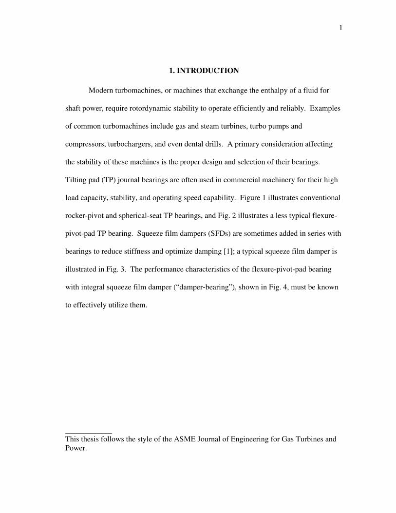
load capacity, stability, and operating speed capability. Figure 1 illustrates conventional
rocker-pivot and spherical-seat TP bearings, and Fig. 2 illustrates a less typical flexure-
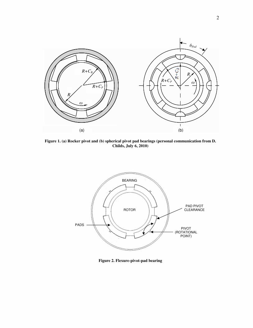
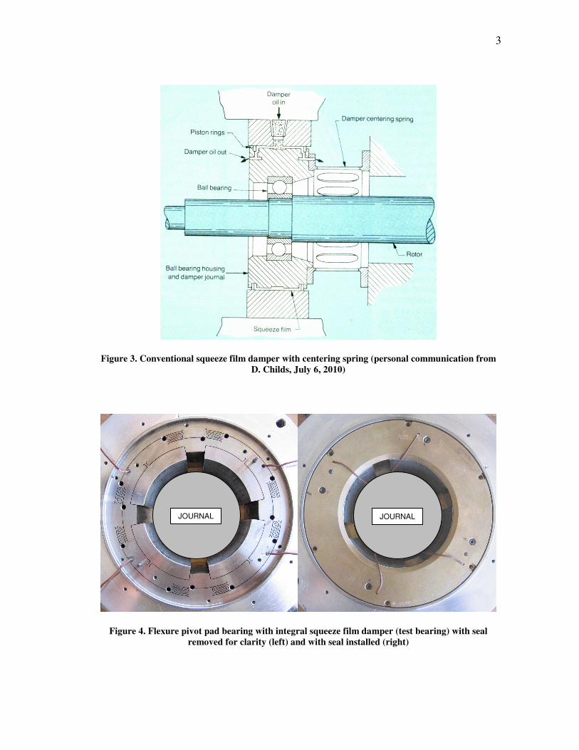
pivot-pad TP bearing. Squeeze film dampers (SFDs) are sometimes added in series with
bearings to reduce stiffness and optimize damping [1]; a typical squeeze film damper is
illustrated in Fig. 3. The performance characteristics of the flexure-pivot-pad bearing
with integral squeeze film damper (“damper-bearing”), shown in Fig. 4, must be known
to effectively utilize them.
____________
This thesis follows the style of the ASME Journal of Engineering for Gas Turbines and
Power.
2
Figure 1. (a) Rocker pivot and (b) spherical pivot pad bearings (personal communication from D.
Childs, July 6, 2010)
Figure 2. Flexure-pivot-pad bearing
ROTOR
BEARING
PIVOT (ROTATIONAL
POINT)
PADS
PAD PIVOT CLEARANCE
(a) (b)
R+CB
R
ω
ω
R
R+CP
R+CP
θPad
3
Figure 3. Conventional squeeze film damper with centering spring (personal communication from
D. Childs, July 6, 2010)
Figure 4. Flexure pivot pad bearing with integral squeeze film damper (test bearing) with seal
removed for clarity (left) and with seal installed (right)
JOURNAL JOURNAL
4
Bearing concepts and background
Unlike the conventional TP bearings shown in Fig. 1 above, flexure-pivot-pad
journal bearings (FPJBs) are of a single-piece wire EDM (Electric Discharge Machine)
construction as shown in Fig. 4. The advantage of FPJBs over conventional TP journal
bearings is that their pivot is not a frictional interface of two moving parts that can wear,
but instead is a simple beam element that flexes within its elastic region. Similarly,
while standard TP bearings must be machined of multiple pieces and assembled, FPJBs
practically eliminate the possibility for tolerance stackup which could lead to clearances
that are not per design.
Several geometrical parameters of tilting pad journal bearings are introduced in
Fig. 1, where R is the rotor radius, CB is the radial bearing (minimum) clearance, CP is
the radial pad clearance (or the difference in the pad and rotor radii), θPad is the pivot
offset, and ω is rotor speed. Tilting pad bearing pads can be machined to a different
radius than the bearing bore, resulting in the dimensionless preload κ defined below.
Positive bearing preload is a common industry practice and ensures an always
converging lubricant film and hydrodynamic pressure generation, thus encouraging
rotor-bearing stability [2].
κ = 1 – CP/CB (1)
The pivot offset, θPad, is the circumferential location of the pad pivot as measured
from the pad leading edge, and is often expressed as a percentage of the circumferential
pad length. While a 50% offset (shown) is typical, offset pivots are sometimes used to
5
reduce operating temperatures or increase stiffness without reducing damping and
increasing bearing temperature [3].
Assuming the weight of the rotor is acting downward, Fig. 1 also shows the two
different loading arrangements possible with tilting pad bearings: (a) load between pads
(LBP) and (b) load on pad (LOP). Load between pads is the generally preferred loading
arrangement for heavy rotors spinning at relatively low speeds because of higher load
capacity, decreased temperature rise due to a more uniformly distributed load, and
greater lateral stiffness and damping [4].
The reaction-force model for a journal bearing is given by Eq. (2), where fbi are
the bearing reaction force components, Kij are the stiffness coefficients, Cij are the
damping coefficients, Mij are the apparent mass (also called “added mass”) coefficients,
and ∆x,∆y are the relative motion (displacement) components between the rotor and
bearing, with each dot representing the successive time derivatives of velocity and
acceleration, respectively. The subscripts indicate the respective directions, where xx
and yy are the direct coefficients and act in the x- and y-directions, and xy and yx are the
cross-coupled coefficients and represent terms that cause a reaction force in a direction
perpendicular to the displacement, velocity, or acceleration direction. Cross-coupled
stiffnesses are undesirable because they promote self-excited vibrations and instabilities
in rotating machinery. Tilting pad journal bearings are characterized by no, or low,
cross-coupled stiffness due to the pads’ ability to freely rotate in response to changes in
load. Flexure pivot pad bearings will have some (low) cross-coupling due to the
rotational stiffness of the pads [3].
6
∆
∆
+
∆
∆
+
∆
∆
=
−
y
x
MM
MM
y
x
CC
CC
y
x
KK
KK
f
f
yyyx
xyxx
yyyx
xyxx
yyyx
xyxx
by
bx
&&
&&
&
& (2)
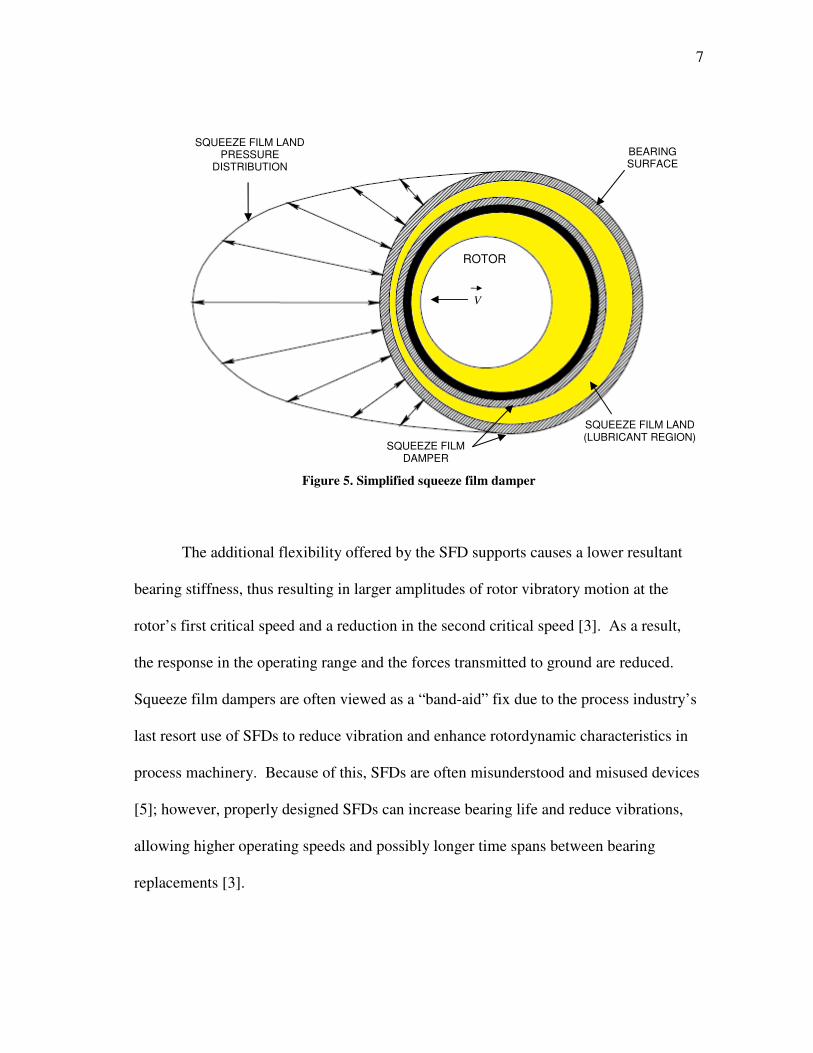
For machines requiring stability enhancement, or with existing vibration
problems, squeeze film dampers (SFDs) are often employed to provide additional
damping and support flexibility to reduce vibration amplitudes, reduce forces transmitted
to ground, and to shift the locations of critical speeds away from the operating range [4].
Squeeze film dampers consist of a stationary outer element, or housing, and (normally) a
flexibly supported inner bearing housing. Oil is fed into the annulus between these
elements, known as the squeeze film land, and perturbations to this land caused by the
radial velocity of the rotor, V, result in the pressure distributions causing damping forces
shown in Fig. 5. Unlike hydrodynamic bearings that rely on the converging-diverging
wedge for pressure generation, the pure squeezing action that takes place between the
inner and outer housings of the SFD provide damping while a support structure, such as
springs, normally provides the stiffness of the SFD.
7
Figure 5. Simplified squeeze film damper
The additional flexibility offered by the SFD supports causes a lower resultant
bearing stiffness, thus resulting in larger amplitudes of rotor vibratory motion at the
rotor’s first critical speed and a reduction in the second critical speed [3]. As a result,
the response in the operating range and the forces transmitted to ground are reduced.
Squeeze film dampers are often viewed as a “band-aid” fix due to the process industry’s
last resort use of SFDs to reduce vibration and enhance rotordynamic characteristics in
process machinery. Because of this, SFDs are often misunderstood and misused devices
[5]; however, properly designed SFDs can increase bearing life and reduce vibrations,
allowing higher operating speeds and possibly longer time spans between bearing
replacements [3].
SQUEEZE FILM DAMPER
ROTOR
V
SQUEEZE FILM LAND (LUBRICANT REGION)
BEARING SURFACE
SQUEEZE FILM LAND PRESSURE
DISTRIBUTION
8
A good amount of research has been performed on flexure-pivot-pad bearings
(FPJBs). Al-Ghasem and Childs [6] provides perhaps the most relevant data, testing a
FPJB in the same LBP loading configuration and with the same preload as the current
test bearing. Al-Ghasem’s curve fits for the experimental dynamic stiffnesses generally
indicated good quadratic curve fits for the real portion of the dynamic stiffnesses and
good linear curve fits for the imaginary portions of the dynamic stiffnesses (indicating
that damping remains constant with changing excitation frequency). XLTRC2-
XLTFBrg©, a Texas A&M University rotordynamics software, was used for predicting
performance, and in most cases provided good matches to experimental rotordynamic
coefficients for direct coefficients, but generally poorly matched experimental cross-
coupled coefficients. The code also under predicts the eccentricity and attitude angle.
Power loss predictions are good, increasing with accuracy as the static load increases.
Rodriguez [7] provides test results for the same FPJB as Al-Ghasem [6], but in
load-on-pad (LOP) configuration. Similar results to [6] were observed with the dynamic
stiffness curve fits. The software provided good stiffness predictions, but often under-
predicts damping and added mass coefficients by around 30%. Rodriguez concludes that
the use of the 2x2 added mass matrix of Eq. (2) provides an improved model, and that
the direct added mass terms may significantly affect rotordynamic calculations,
particularly for light rotors.
San Andrès and De Santiago [8-13] supply the majority of the available literature
for the damper-bearing. In one study [8], they provide test results for a rotor mounted on
two identical damper bearings, for both a locked and active damper, and excited
9
identical imbalances. Results show higher peak amplitudes of vibration for the damper-
bearing than for the FPJB (due to the extra clearance provided by the damper); however,
operation with the damper (damper-bearing) resulted in increased tolerance to
imbalance. In fact, the damper allowed safe operation of the rotor with imbalances twice
as large as with the FPJB alone. Reductions in critical speed of up to 10% were
recognized for the highest imbalance condition. Low cross-coupled stiffness was
evidenced by the shaft centerline moving along a nearly vertical path during coast down
tests.
San Andrés and De Santiago [10] also used imbalance masses in two planes to
provide synchronous excitation to the same rotor, this time supported by a damper-
bearing on one end and a plain journal bearing with a conventional SFD on the other
end. Predictions made for the system estimated that coefficients change more as a
function of rotor speed than of excitation frequency. At low rotor speeds, the direct
stiffnesses were found to correspond to the structural support stiffnesses of the squeeze
film dampers. Equivalent synchronous damping coefficients were found to decrease
steadily with increased rotor speed, for most of the speed range tested.
De Santiago et al. [11] design and construct a damper-bearing and predict the
imbalance response for it to show the effect on the location of critical speeds and
effective damping of the series combination. Optimum selection of stiffness and
damping for minimization of rotor response is described, as well as a 38-station transfer-
matrix model that predicts the imbalance response of the rotor-bearing system. In a
follow up paper [12], these predictions are compared to measured imbalance response
10
results. Results show a marked decrease in the first critical speed of the rotor-bearing
system, with small variations between the experiments and predictions. The predicted
peak-to-peak responses are generally close to the experimental results in the horizontal
direction, but a resonance in the support is not well accounted for in the vertical
direction. Results of no-imbalance coast down experiments are also shown compared to
ball bearings with ISFDs and evidence very low viscous drag – taking more than 10
minutes for the decelerating rotor to come a full stop. A linear relationship between
peak vibration amplitude at the critical speed and imbalance displacement is observed.
Using calibrated impact hammer strikes to provide excitation at null running speed, the
system damping coefficient is shown to increase by an average of 11% and 18% over the
ISFD alone (mounted on ball bearings) in the horizontal and vertical directions,
respectively. FPJB results are also presented and show the tilting pad bearing can
tolerate imbalances less than the bearing clearances; however, the damper-bearing can
handle much greater imbalances with reduced force transmissibility.
Only one paper detailing an industrial application of flexure-pivot-pad bearings
with integral squeeze film dampers is presently known to the author. In this case, Locke
and Faller [14] implement the bearing into the design of a high-reliability process
recycle gas compressor. Suction contaminants of an abrasive and corrosive sticky
material capable of severely eroding (nearly consuming) the radial compressor impeller
in less than ten days required a machine with high stability and tolerance to imbalance,
able to continue processing after significant deterioration of the impeller vanes. The
damping provided by a FPJB alone was insufficient for the application, so additional
11
damping was provided using an ISFD. During normal operation at 10000 rpm, buildups
of material from the sticky process stream routinely occur on the impeller, and the
damper-bearing design tolerated the imbalance due to buildups better than a similar
machine on another process line. Although buildups occasionally caused the vibration
amplitude to exceed 25.4 µm (1 mil), the damper-bearing configuration sufficiently
absorbs the energy to keep bearing temperatures in line with requirement and allow
operation until scheduled outages. During shop testing, an imbalance corresponding to
deterioration by a factor of more than ten with respect to normal balance quality was
applied to the rotor. Also, the location of the critical speed was found to be at 60 percent
of operating speed, while being predicted at around 40 percent, which questioned the
current ability to accurately predict characteristics of the damper-bearing assembly. In
the end, however, the actual test results were satisfactory with maximum vibrations
being only about 10 percent above the predictions, making for a stable compressor
tolerant to high imbalance.
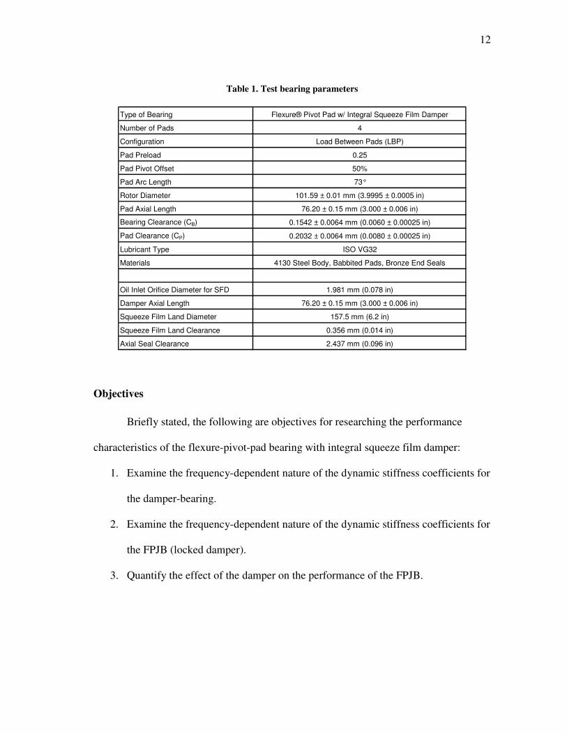
Test Bearing: Flexure-Pivot-Pad Bearing with Integral Squeeze Film Damper
The test bearing (shown previously in Fig. 4) is a one piece, wire EDM, flexure-
pivot-pad bearing with integral squeeze film damper manufactured by Bearings Plus,
Inc. (BPI). Oil is fed to the bearing by two supply hoses stationed 180-degrees apart and
enters a supply groove located circumferentially around the bearing. Eight ports are
located in the supply groove – four supply oil to the bearing (one between each set of
pads) and the other four have orifices which supply oil to the SFD. A list of the bearing
parameters is provided in Table 1.
12
Table 1. Test bearing parameters
Type of Bearing Flexure® Pivot Pad w/ Integral Squeeze Film Damper
Number of Pads 4
Configuration Load Between Pads (LBP)
Pad Preload 0.25
Pad Pivot Offset 50%
Pad Arc Length 73°
Rotor Diameter 101.59 ± 0.01 mm (3.9995 ± 0.0005 in)
Pad Axial Length 76.20 ± 0.15 mm (3.000 ± 0.006 in)
Bearing Clearance (CB) 0.1542 ± 0.0064 mm (0.0060 ± 0.00025 in)
Pad Clearance (CP) 0.2032 ± 0.0064 mm (0.0080 ± 0.00025 in)
Lubricant Type ISO VG32
Materials 4130 Steel Body, Babbited Pads, Bronze End Seals
Oil Inlet Orifice Diameter for SFD 1.981 mm (0.078 in)
Damper Axial Length 76.20 ± 0.15 mm (3.000 ± 0.006 in)
Squeeze Film Land Diameter 157.5 mm (6.2 in)
Squeeze Film Land Clearance 0.356 mm (0.014 in)
Axial Seal Clearance 2.437 mm (0.096 in)
Objectives
Briefly stated, the following are objectives for researching the performance
characteristics of the flexure-pivot-pad bearing with integral squeeze film damper:
1. Examine the frequency-dependent nature of the dynamic stiffness coefficients for
the damper-bearing.
2. Examine the frequency-dependent nature of the dynamic stiffness coefficients for
the FPJB (locked damper).
3. Quantify the effect of the damper on the performance of the FPJB.

13
4. Evaluate the accuracy of available predictive rotordynamic software, namely the
XLTRC2-XLTFBrg© Rotordynamics Suite to predict static and dynamic bearing
parameters for the FPJB.
14
2. TEST RIG DESCRIPTION
Bearing performance is measured using an existing hydrodynamic bearing test
rig located at the Texas A&M University Turbomachinery Laboratory. Kaul [15]
provides a detailed description of the test rig, originally designed for testing oil seals and
extracting rotordynamic coefficients.
Main Test Rig
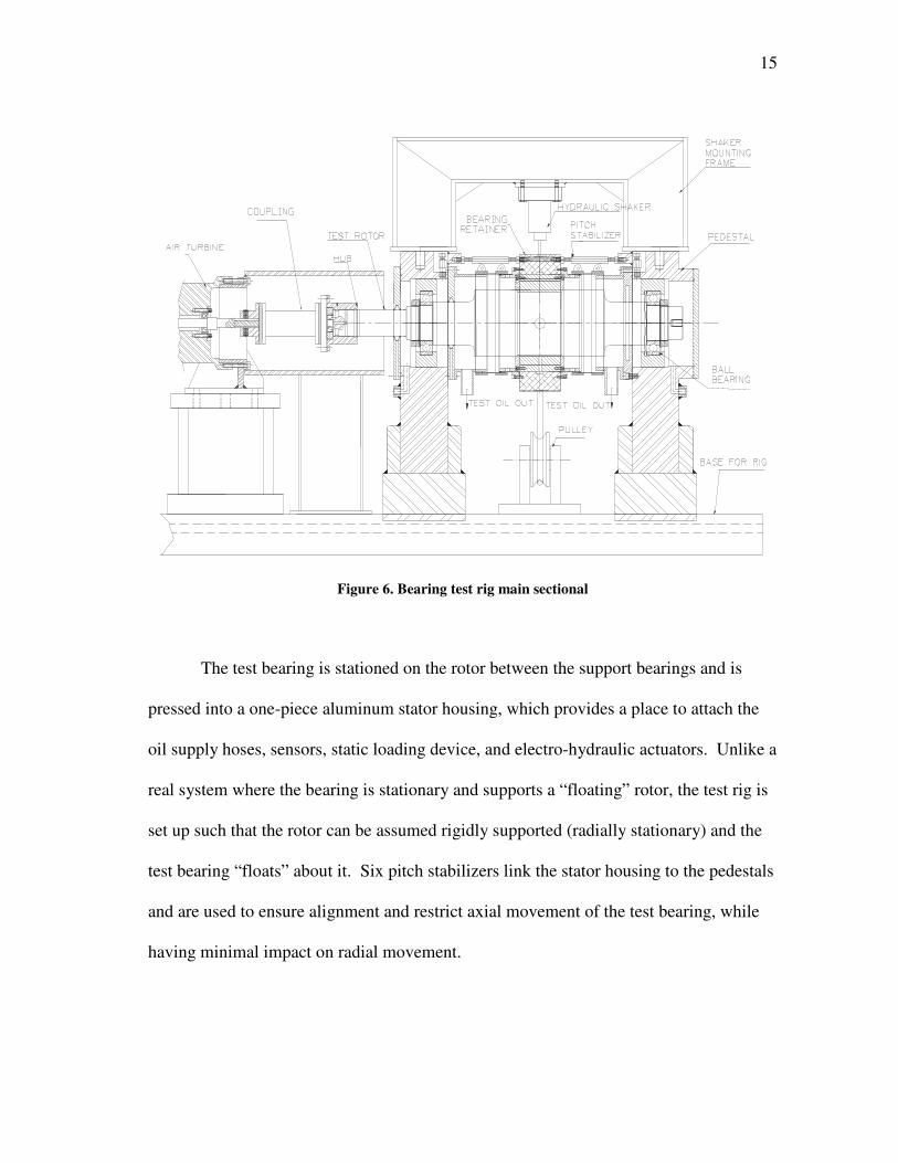
The main sectional of the test rig is shown in Fig. 6. A mild steel plate box
supports a 76.2 mm (3 in) T-slot top, forming the foundation for the main section and
prime mover. The stainless steel test rotor is precision machined to a diameter of 101.59
mm (3.9995 in) and was dynamically balanced immediately prior to the testing described
hereafter. The rotor is supported by high-speed ball bearings pressed onto each end.
Two steel pedestals, spaced approximately 381 mm (15 in) apart and fixed to the base,
cradle the shaft at the support bearing locations. A framework attached to the pedestals
encases and secures the support bearings, provides a mounting place for electro-
hydraulic actuators, and ties the main test rig together. An oil mist generator provides
lubrication to the support bearings, and two air buffer seals between the pedestals
prevent the oil mist from leaking into the test bearing lubricant discharge chambers. A
vacuum seal on the drive end (DE) and draining rotor end cap on the non-drive end
(NDE) are used to evacuate the support bearing lubricant oil.
15
Figure 6. Bearing test rig main sectional
The test bearing is stationed on the rotor between the support bearings and is
pressed into a one-piece aluminum stator housing, which provides a place to attach the
oil supply hoses, sensors, static loading device, and electro-hydraulic actuators. Unlike a
real system where the bearing is stationary and supports a “floating” rotor, the test rig is
set up such that the rotor can be assumed rigidly supported (radially stationary) and the
test bearing “floats” about it. Six pitch stabilizers link the stator housing to the pedestals
and are used to ensure alignment and restrict axial movement of the test bearing, while
having minimal impact on radial movement.
16
The oil supply system feeds temperature controlled ISO VG32 turbine oil to the
test bearing via two hoses attached to the bearing housing, located horizontally opposite
each other. Lubricant flow rate is adjusted by means of a user-controlled pneumatic
valve, and lubricant temperature is controlled by a forced air heat exchanger. A
maximum practical oil flow rate of 61 l/min (16 gpm) is achievable. Supply oil exits the
test bearing axially and is contained in the test rig by rubber sleeves connecting the test
bearing to the pedestals. The oil exits the test rig through the discharge chambers
located against the pedestals on either side of the test bearing.
A high-speed flexible disc coupling attaches the rotor to a direct-drive air turbine,
which runs on externally supplied compressed air. The turbine can run to 17000 rpm
and deliver 67 kW (90 hp) of power. Shaft speed is adjustable via a user-controlled
electro-pneumatic valve that regulates the air flow to the turbine.
Static and Dynamic Loading
Static loading is applied to the bearing stator housing by a pneumatic cylinder,
with a spring and cable system linking the cylinder’s piston to the stator housing via a
pulley, as shown in Fig. 7. The spring ensures a constant load by isolating the motion of
the bearing from that of the piston, and the pulley guarantees that the load is purely
radial and in one direction. A user-controlled electro-pneumatic valve adjusts the static
load produced by the cylinder from zero to 20 kN (4500 lbf), using the 827 kPa (120 psi)
air supply pressure.
17
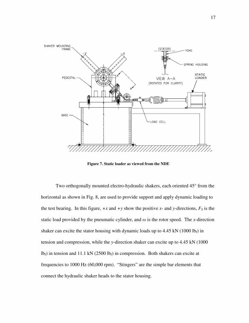
Figure 7. Static loader as viewed from the NDE
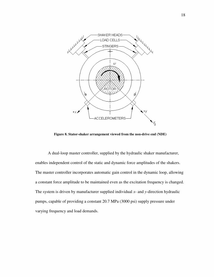
Two orthogonally mounted electro-hydraulic shakers, each oriented 45° from the
horizontal as shown in Fig. 8, are used to provide support and apply dynamic loading to
the test bearing. In this figure, +x and +y show the positive x- and y-directions, FS is the
static load provided by the pneumatic cylinder, and ω is the rotor speed. The x-direction
shaker can excite the stator housing with dynamic loads up to 4.45 kN (1000 lbf) in
tension and compression, while the y-direction shaker can excite up to 4.45 kN (1000
lbf) in tension and 11.1 kN (2500 lbf) in compression. Both shakers can excite at
frequencies to 1000 Hz (60,000 rpm). “Stingers” are the simple bar elements that
connect the hydraulic shaker heads to the stator housing.
STATIC LOADER
18
Figure 8. Stator-shaker arrangement viewed from the non-drive end (NDE)
A dual-loop master controller, supplied by the hydraulic shaker manufacturer,
enables independent control of the static and dynamic force amplitudes of the shakers.
The master controller incorporates automatic gain control in the dynamic loop, allowing
a constant force amplitude to be maintained even as the excitation frequency is changed.
The system is driven by manufacturer supplied individual x- and y-direction hydraulic
pumps, capable of providing a constant 20.7 MPa (3000 psi) supply pressure under
varying frequency and load demands.
19
Instrumentation
Several measurements of the oil conditions and relative rotor-bearing movements
are required to determine bearing performance. The ISO VG32 supply oil flow rate is
measured via a flow meter. Inlet oil supply temperature is measured using a K-type
thermocouple in the bearing oil supply groove, and outlet temperature is measured by
two similar thermocouples, located in the end caps immediately on either side of the
stator housing. Static pressure transducers measure the inlet oil pressure in the bearing
oil supply groove (around 165 kPa, or 24 psi) and the outlet oil pressure in the bearing
end caps (close to ambient). A series of fourteen thermocouples located within the
bearing pads and eight thermocouples along the squeeze film land record the metal
temperatures at these locations.
Four non-contacting eddy current proximity probes measure the relative rotor-
bearing position in two orthogonal directions (x- and y-directions) and in two parallel
planes (in each of the two bearing end caps). Position measurements in two planes allow
for assessment of bearing pitch and yaw, while orthogonal directions provides
measurements in both dimensions of travel. A strain gauge attached between the spring
and cable on the static loader measures the static load applied to the bearing. Rotor
speed is measured using a keyphasor arrangement.
Dynamic loading of the hydraulic shakers is measured by load cells located
between the stinger-shaker assemblies, shown in Fig. 8. Accelerometers mounted to the
stator housing measure the absolute acceleration of the bearing-stator in the x- and y-
directions.

20
3. PRELIMINARY TESTING AND RESULTS
Preliminary testing was required to determine the bearing pad rotational
(structural) stiffness and damping values, and the squeeze film damper spring stiffness,
for later use as inputs in the rotordynamic predictive software. Prior to this testing,
compressed air was blown through all of the bearing and squeeze film damper grooves
to ensure a clean and dry bearing.
Bearing Pad Rotational Stiffness and Damping
Beam Theory Pad Stiffness
The rotational stiffness and damping of the bearing pads are not directly
measured, but rather are calculated using measured values. Two methods are presented
for determining rotational stiffness, and one is further refined to determine pad damping.
First, the beam theory for a cantilever beam is used to calculate rotational stiffness; then,
a pad mounted accelerometer is used to measure the vibratory response of the pad to an
impact, from which the rotational stiffness and damping can be calculated.
The calculation of the pad rotational stiffness using beam theory assumes the
pad’s web behaves like a cantilever beam, fixed at one end and with a moment applied at
the free end, as shown in Fig. 9. Note that h is the height of the web and w is the width
of the web.
21
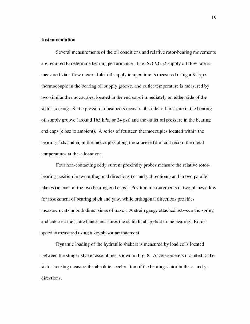
Figure 9. Cantilever beam model of pad web (modified from [7])
The equation for the rotational stiffness of a cantilever beam can be found in
most texts on mechanics of materials, such as Hibbeler [16], and is given in Eq. (3)
where kθ,pad is the rotational stiffness, E is the material modulus of elasticity, Ia is the
area moment of inertia of the web cross-section defined in Eq. (4), and L is the web
length (in this case equal to the pad length). The fillets shown at the top and bottom of
the web are assumed to add some flexibility, so h is presented as the centerline distance
between the top and bottom fillets. Using measured pad dimensions, application of these
equations yields a pad rotational stiffness of 1758 N.m/rad.
h
EIk a
pad =,θ (3)
3
12
1LwI a = (4)
Moment
h
w
L
FIXED
22
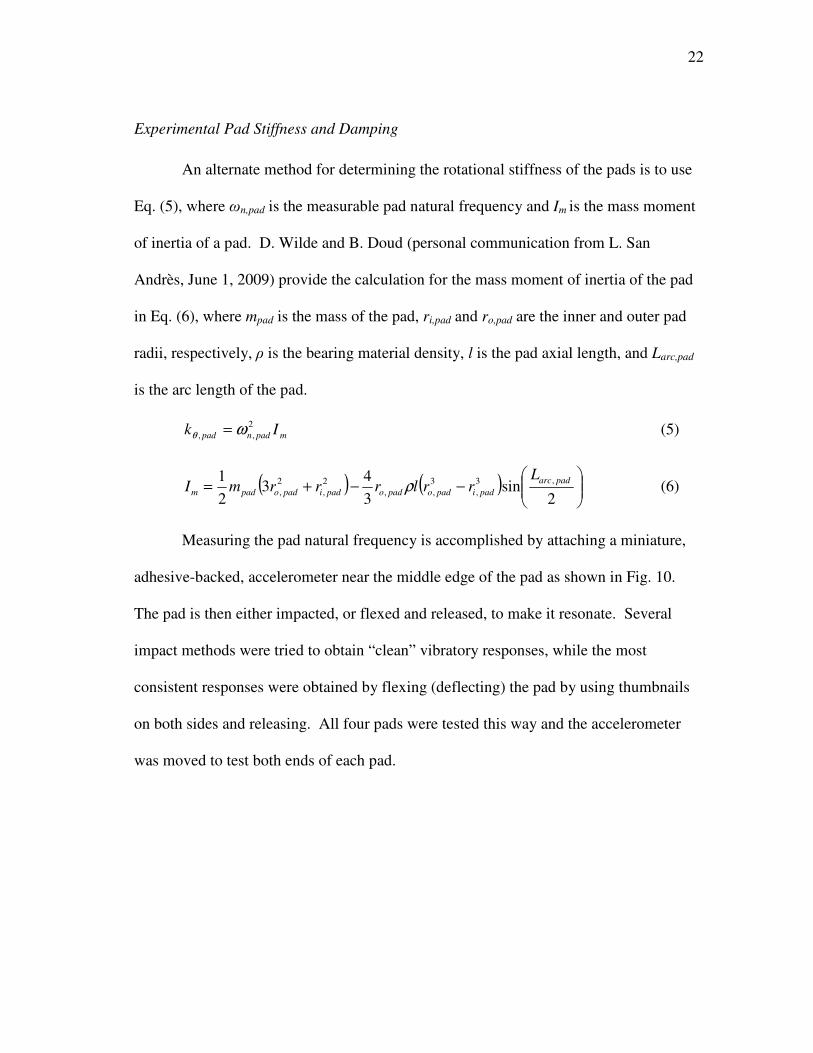
Experimental Pad Stiffness and Damping
An alternate method for determining the rotational stiffness of the pads is to use
Eq. (5), where ωn,pad is the measurable pad natural frequency and Im is the mass moment
of inertia of a pad. D. Wilde and B. Doud (personal communication from L. San
Andrès, June 1, 2009) provide the calculation for the mass moment of inertia of the pad
in Eq. (6), where mpad is the mass of the pad, ri,pad and ro,pad are the inner and outer pad
radii, respectively, ρ is the bearing material density, l is the pad axial length, and Larc,pad
is the arc length of the pad.
mpadnpad Ik2
,, ωθ = (5)
( ) ( )
−−+=
2sin
3
43
2
1 ,3
,
3
,,
2
,
2
,
padarc
padipadopadopadipadopadm
LrrlrrrmI ρ (6)
Measuring the pad natural frequency is accomplished by attaching a miniature,
adhesive-backed, accelerometer near the middle edge of the pad as shown in Fig. 10.
The pad is then either impacted, or flexed and released, to make it resonate. Several
impact methods were tried to obtain “clean” vibratory responses, while the most
consistent responses were obtained by flexing (deflecting) the pad by using thumbnails
on both sides and releasing. All four pads were tested this way and the accelerometer
was moved to test both ends of each pad.
23
Figure 10. Accelerometer location on bearing pad (modified from [7])
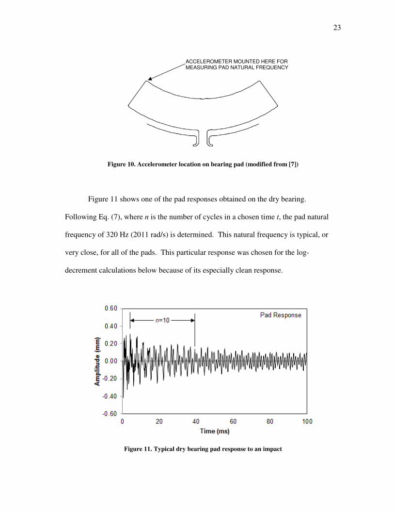
Figure 11 shows one of the pad responses obtained on the dry bearing.
Following Eq. (7), where n is the number of cycles in a chosen time t, the pad natural
frequency of 320 Hz (2011 rad/s) is determined. This natural frequency is typical, or
very close, for all of the pads. This particular response was chosen for the log-
decrement calculations below because of its especially clean response.
Figure 11. Typical dry bearing pad response to an impact
ACCELEROMETER MOUNTED HERE FOR MEASURING PAD NATURAL FREQUENCY
24
=
t
npadn πω 2, (7)
Following Eq. (6), the pad mass moment of inertia is calculated to be 295(10-6
)
kg-m2. Combining this with the natural frequency just found, Eq. (5) results in a pad
stiffness of 1194 N.m/rad. Although this stiffness is considerably (32%) lower than the
1758 N.m/rad calculated previously using beam theory, it is used as the rotational
stiffness in the predictive software since it is the most accurate (experimental), and the
method also provides pad damping (described next). To satisfy scientific curiosity,
beam theory and experimental rotational stiffnesses were compared by predicting
rotordynamic coefficients using the prediction software, and the experimental rotational
stiffness provided the best (closest to experimental) overall results.
Pad damping is determined using Fig. 11, and Eqs. (8) and (9), where δ is the
logarithmic decrement, N is the number of peaks in the desired response period (N = n –
2, using Fig. 11), y1 and yN are are the beginning and ending response amplitudes,
respectively, ζ is the damping ratio, Cpad is pad damping, and the other symbols are
previously defined. Using the range and corresponding values in Fig. 11, the mass
moment of inertia calculated using Eq. (6), and either of the previously determined
rotational stiffnesses results in practically zero pad damping (approximately 0.01 N.s/m).
2
1
1
2ln
1
1
ζ
πζδ
−=
−=
Ny
y
N (8)
padmpadpad IkC ,,2 θζ= (9)
25
Squeeze Film Damper Structural Stiffness
The squeeze film damper structural stiffness is an input used in the rotordynamic
prediction software. The stiffness was experimentally measured, and verified using
finite element analysis (FEA) software.
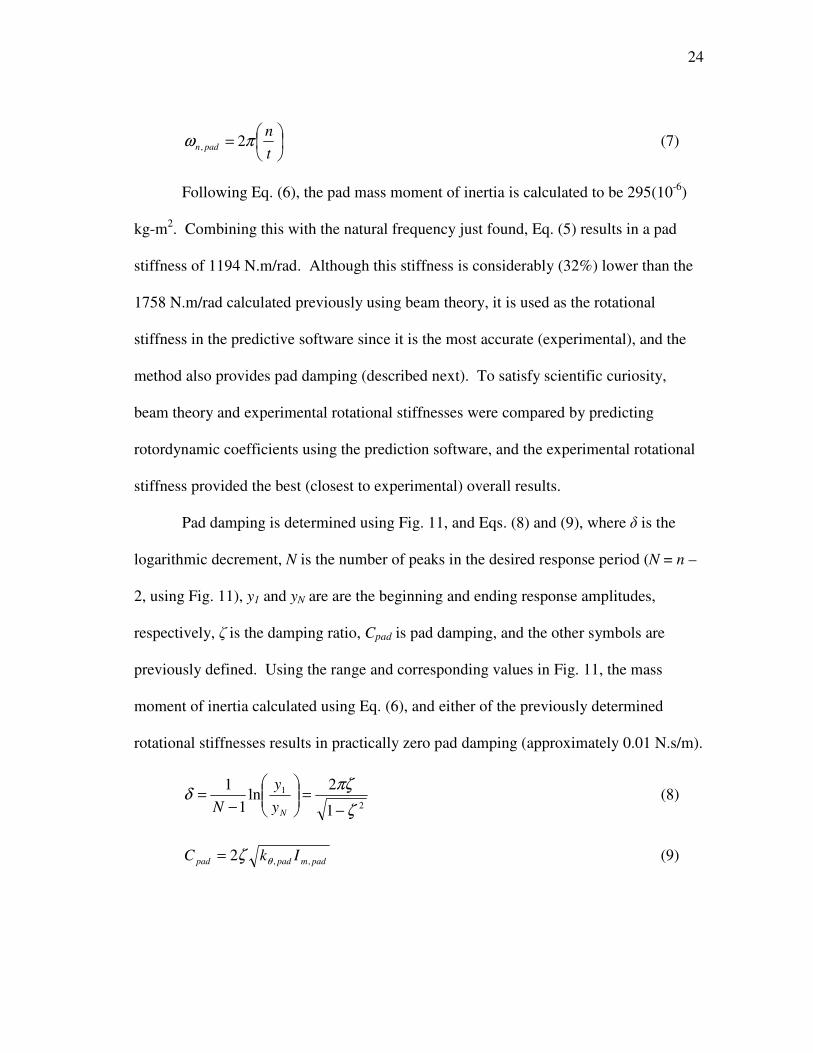
Measured of Damper Stiffness
The subject bearing is tested in a load-between-pads (LBP) configuration,
meaning that two pads are loaded. For measuring the SFD stiffness, the loaded pads
were shimmed using strips of brass sheet to negate their deflection, as shown in Fig. 12.
The end seals are left off the bearing and the test rig is normally assembled, except that
all unnecessary items are left unattached. Two displacement probes are used (DE and
NDE), both measuring in the y-direction (direction of load) but in separate planes, and
are averaged for each reading.
Figure 12. Loaded pads shimmed for damper stiffness measurements
SHIMS INDICATED BY ARROWS
26
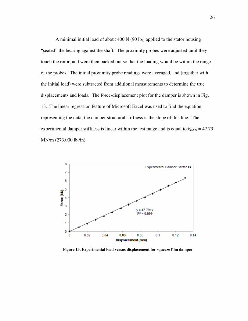
A minimal initial load of about 400 N (90 lbf) applied to the stator housing
“seated” the bearing against the shaft. The proximity probes were adjusted until they
touch the rotor, and were then backed out so that the loading would be within the range
of the probes. The initial proximity probe readings were averaged, and (together with
the initial load) were subtracted from additional measurements to determine the true
displacements and loads. The force-displacement plot for the damper is shown in Fig.
13. The linear regression feature of Microsoft Excel was used to find the equation
representing the data; the damper structural stiffness is the slope of this line. The
experimental damper stiffness is linear within the test range and is equal to kISFD = 47.79
MN/m (273,000 lbf/in).
Figure 13. Experimental load versus displacement for squeeze film damper
27
Predicted Damper Stiffness
As an exercise in confirming the measured results, finite element analysis (FEA)
was used to predict the damper structural stiffness. Key dimensions of the test bearing
were measured and used to create a solid model in SolidWorks and the COSMOSXpress
package was used for the analysis. In the analysis, four different loads were applied to
the damper, and the displacements were estimated at the squeeze film land near the load
location, from which the damper stiffness was determined. For analysis efficiency, some
damper-bearing features were not included or were modified in the model. For example,
the cuts forming the bearing pads are filled in, and the axial length is reduced from 76.2
mm to 25.4 mm (3 in to 1 in). The bearing pad outline cuts have no effect on the damper
stiffness, and the change in axial length is easily accounted for by multiplying the
resulting stiffness by the ratio of the reduction in axial length (3). These modifications
result in a model that is both smaller and less complex, meaning that a greater number of
smaller elements can be used, resulting in a more accurate and equally (or more) time
efficient analysis.
Figure 14 shows the bearing model and how it is (a) restrained and (b) loaded in
the analyses. Individual loads of 0.4, 0.8, 1.2, and 1.6 kN were used in the analyses.
Each analysis generates an exaggerated deformation plot that uses a color scale to
determine the deformation, as shown in Fig. 15; the predicted deflection is estimated
from this deformation plot.

28
Figure 14. (a) Restraint and (b) load locations for FEA damper analysis
Figure 15. Exaggerated scale damper deformation for 0.4 kN load
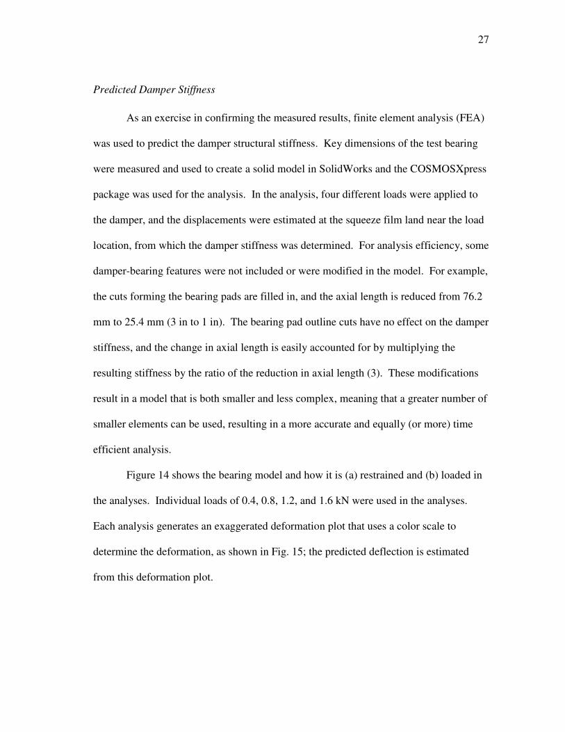
The applied loads and displacements predicted by COSMOS are plotted in Fig.
16. As with the measured results, the predicted damper stiffness is the slope of this
graph, or 43.29 MN/m (247,216 lbf/in). This value differs from the measured damper
(a) (b)
DEFLECTION POINT OF INTEREST
RESTRAINT
LOAD
29
stiffness by about 9.5%, thereby confirming the previously measured results and
suggesting that FEA can provide good results for the complex design of integral squeeze
film dampers.
Figure 16. Predicted damper stiffness results using FEA

30
4. EXPERIMENTAL PROCEDURES AND PARAMETER IDENTIFICATION
As stated previously, two different bearing configurations are tested – locked and
active squeeze film damper. For the first case, the damper was locked by inserting pins
into all of the holes along the squeeze film land, as shown in Fig. 17. Care was taken to
fit individual pins to each hole to avoid adversely affecting bearing dimensions. Pins
were used rather than shims because they are easily removable (can be removed), yet
still allow the end seals to be installed (shims would have to be folded at the end to be
removable, which would prevent the seal from fully seating).
Figure 17. Damper is locked using pins
The test procedures for both bearing configurations are the same, except for
minor differences concerning the bearing centering process and squeeze film land
temperature measurements are taken for the active damper case, as discussed below.
PINS INSERTED IN ALL SIMILAR
HOLES
END SEAL ALIGNMENT PINS
SQUEEZE FILM LAND
31
Data reduction and parameter identification processes are identical for both bearing
configurations.
Centering the Bearing
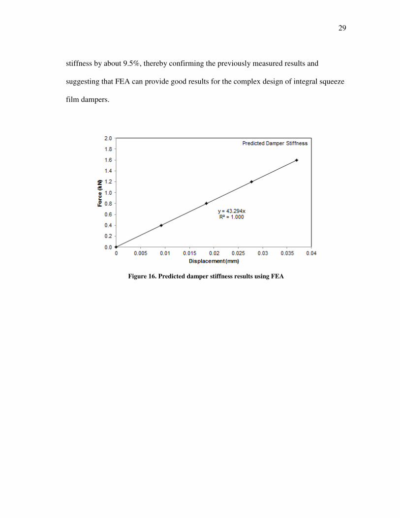
Prior to initiating the static and dynamic testing, the bearing center must be
found. This process consists of moving the bearing to its extremes about two
perpendicular axes and marking these points on an oscilloscope readout. The bearing
center is then the center of the extremes. The centering process is depicted in Fig. 18
and a summary follows.
Figure 18. Process for finding bearing center
y
x
45°
INITIAL POSITION
STEP 1
STEP 2
x’
y’

32
Step 1: The bearing is moved from an initial position along an axis at a 45° angle
relative to the x-axis until contact is made with the rotor. The bearing is
then moved along the same axis in the opposite direction until contact is
made. Note that determining contact FPJB (locked damper) is relatively
easy using the oscilloscope; however, the additional flexibility of the
active damper (damper-bearing) makes this difficult. For the damper-
bearing, contact between the bearing and rotor is determined by touch –
the shaft is rotated by hand and the bearing is pulled just to the point
where it can no longer be easily turned.
Step 2: The middle of the two extremes found in step 1 is determined, and the
bearing is moved to the perpendicular extremes of the middle of that axis.
The middle of this axis should be the same as the bearing center.
Step 3: The center of the bearing is verified by checking that the bearing
clearance is equal along orthogonal axes oriented 45° relative to the x-
axis (this is the distance from the rotor to the circumferential pad center).
Step 4: If the clearances are not equal in step 3, steps 1-3 are repeated.
Static Load Test Procedure
After completing the bearing centering procedure, pitch and yaw are adjusted
using the pitch stabilizers until the DE and NDE displacement probes have equivalent
readings to ensure the bearing is properly aligned with the rotor. The oil flow rate is set
to a constant 45.4 l/min (12 gpm) for all tests to ensure a flooded bearing. After other
initial test rig startup procedures, the air turbine is ramped up to test speed, and the
33
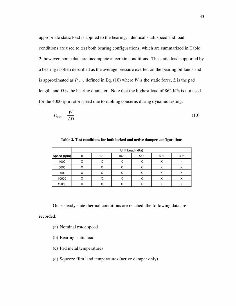
appropriate static load is applied to the bearing. Identical shaft speed and load
conditions are used to test both bearing configurations, which are summarized in Table
2; however, some data are incomplete at certain conditions. The static load supported by
a bearing is often described as the average pressure exerted on the bearing oil lands and
is approximated as PStatic defined in Eq. (10) where W is the static force, L is the pad
length, and D is the bearing diameter. Note that the highest load of 862 kPa is not used
for the 4000 rpm rotor speed due to rubbing concerns during dynamic testing.
LD
WPStatic = (10)
Table 2. Test conditions for both locked and active damper configurations
0 172 345 517 689 862
4000 X X X X X -
6000 X X X X X X
8000 X X X X X X
10000 X X X X X X
12000 X X X X X X
Unit Load (kPa)
Speed (rpm)
Once steady state thermal conditions are reached, the following data are
recorded:
(a) Nominal rotor speed
(b) Bearing static load
(c) Pad metal temperatures
(d) Squeeze film land temperatures (active damper only)
34
(e) Oil supply and exit temperatures
(f) Oil supply pressure
(g) x- and y-direction DE and NDE displacement probe readings
Static Load Parameter Identification
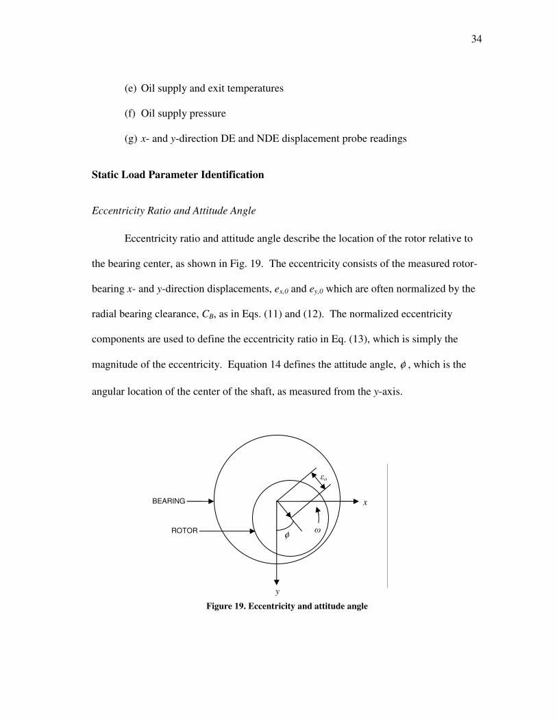
Eccentricity Ratio and Attitude Angle
Eccentricity ratio and attitude angle describe the location of the rotor relative to
the bearing center, as shown in Fig. 19. The eccentricity consists of the measured rotor-
bearing x- and y-direction displacements, ex,0 and ey,0 which are often normalized by the
radial bearing clearance, CB, as in Eqs. (11) and (12). The normalized eccentricity
components are used to define the eccentricity ratio in Eq. (13), which is simply the
magnitude of the eccentricity. Equation 14 defines the attitude angle, φ , which is the
angular location of the center of the shaft, as measured from the y-axis.
Figure 19. Eccentricity and attitude angle
εo
φ
y
ω
x BEARING
ROTOR
35
B
ox
oxC
e ,
, =ε (11)
B
oy
oyC
e ,
, =ε (12)
2
,
2
, oyoxo εεε += (13)
= −
oy
ox
e
e
,
,1tanφ (14)
Temperature Dependent Lubricant Properties
Some calculations require temperature dependent lubricant properties for the
supply oil (ISO VG32). The XLTRC2© help menu contains the temperature dependent
relationships for viscosity (µ), density (ρ), and specific heat (cP) in Eqs. (15), (16), and
(17) where T is the temperature in Kelvin that the property is evaluated at.
( )2611.294030069.0045336.0 −−= Teµ [Pa.s] (15)
10646616.0 +−= Tρ [kg/m3] (16)
75.8116273.3 += Tγ [kJ/kg.K] (17)
Power Loss
Frictional power loss in fluid film bearings occurs primarily due to the no slip
condition on the rotor and bearing surfaces, resulting in shearing action between the
lubricant film layers. The shear stresses that develop produce a resistive (drag) torque
on the shaft and dissipate this energy as heat. Since the test rig cannot measure drag

36
torque, a thermal approach is instead used to estimate the bearing power loss. This
approach is considered an estimate because it assumes that all of the frictional energy
goes directly and only into heating the oil, and therefore assumes no heat is lost through
any other part of the test rig. The estimated frictional power loss, Ploss, is found using
Eq. (18) where Q& is the volumetric flow rate of the lubricant, Tin and Tout are the
lubricant supply and exit temperatures, and the other terms are defined above. Since the
test rig allows oil to exit on both the drive end and non-drive end, temperatures are
measured at both locations and averaged to obtain Tout.
[ ]inToutTloss TTQPinout
)()( ργργ −= & (18)
Sommerfeld Number
The Sommerfeld number is a useful parameter for comparing similar bearings
and is defined in Eq. (19), where µ is the lubricant viscosity at the average inlet-exit
temperature, D is the bearing diameter, L is the bearing pad length, Nrpm is the rotor
speed in rpm, W is the static load on the bearing, and CP is the radial pad clearance. The
equation is not all-encompassing and does not include effects for preload or support
stiffness, but enables similar bearings to be compared at the same Sommerfeld number.
Non-dimensionalized rotordynamic coefficients are later compared to coefficients for a
similar bearing to the locked damper case tested by Al-Ghasem [6] at similar
Sommerfeld numbers.
2
260
=
P
rpm
C
DN
W
DLS
µ (19)
37
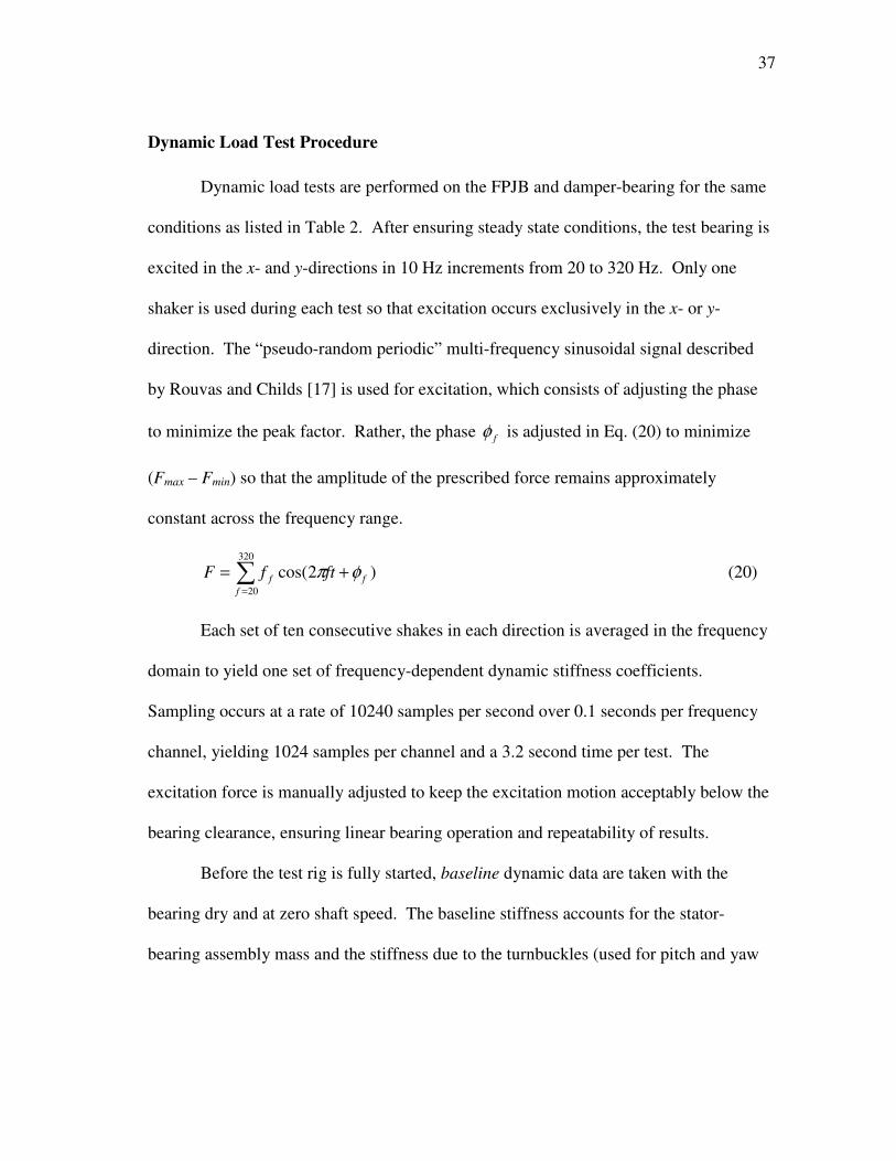
Dynamic Load Test Procedure
Dynamic load tests are performed on the FPJB and damper-bearing for the same
conditions as listed in Table 2. After ensuring steady state conditions, the test bearing is
excited in the x- and y-directions in 10 Hz increments from 20 to 320 Hz. Only one
shaker is used during each test so that excitation occurs exclusively in the x- or y-
direction. The “pseudo-random periodic” multi-frequency sinusoidal signal described
by Rouvas and Childs [17] is used for excitation, which consists of adjusting the phase
to minimize the peak factor. Rather, the phase fφ is adjusted in Eq. (20) to minimize
(Fmax – Fmin) so that the amplitude of the prescribed force remains approximately
constant across the frequency range.
)2cos(320
20
∑=
+=f
ff ftfF φπ (20)
Each set of ten consecutive shakes in each direction is averaged in the frequency
domain to yield one set of frequency-dependent dynamic stiffness coefficients.
Sampling occurs at a rate of 10240 samples per second over 0.1 seconds per frequency
channel, yielding 1024 samples per channel and a 3.2 second time per test. The
excitation force is manually adjusted to keep the excitation motion acceptably below the
bearing clearance, ensuring linear bearing operation and repeatability of results.
Before the test rig is fully started, baseline dynamic data are taken with the
bearing dry and at zero shaft speed. The baseline stiffness accounts for the stator-
bearing assembly mass and the stiffness due to the turnbuckles (used for pitch and yaw
38
adjustment), unused shaker, hoses, ect. and is subtracted from subsequent tests so that
stiffness and damping results are for the bearing only.
Rotordynamic Parameter Identification
A parameter identification model originally developed by Rouvas and Childs
[17] for hydrostatic bearings is used to determine the direct and cross-coupled stiffness,
damping, and added mass coefficients. The testing scheme utilizes multi-frequency
excitation and noise reduction techniques, and power cross-spectral densities are applied
to the data to effectively eliminate the effects of fluid flow induced vibration on the
results. A brief description of the dynamic data reduction model follows.
The equation of motion for the bearing stator is given in Eq. (21), where Ms is the
bearing-stator mass, ax and ay are stator acceleration components measured by stator-
mounted accelerometers, fx and fy are the dynamic forces measured by load cells on each
hydraulic shaker, fb,x and fb,y are the bearing reaction forces, and the x and y subscripts
refer to the x- and y-directions of Fig. 8. Combining and rearranging the terms in the
force-reaction model of Eq. (2) and the equation of motion for the stator housing given
in Eq. (21), yields Eq. (22). The stiffness, damping, and added mass terms are given by
Kij, Cij, and Mij, respectively, while the subscripts (xx, yy) and (xy, yx) refer to the direct
and cross-coupled terms.
−
=
yb
xb
y
x
y
x
s f
f
f
f
a
aM
,
, (21)
∆
∆
−
∆
∆
−
∆
∆
−=
−
−
y
x
MM
MM
y
x
CC
CC
y
x
KK
KK
aMf
aMf
yyyx
xyxx
yyyx
xyxx
yyyx
xyxx
ysy
xsx
&&
&&
&
& (22)

39
The terms making up the left side vector of Eq. (22) are entirely known,
measured functions of time, as is the relative motion of the stator given by ∆x(t) and
∆y(t) on the right side. The Fast Fourier Transform, F, converts Eq. (22) to the
frequency domain version of Eq. (23), where Fk = F(fk), Ak = F(ak), and Dk = F(∆k) is the
k-direction displacement.
−=
−
−
y
x
ysy
xsx
D
D
AMF
AMF
yyyx
xyxx
HH
HH (23)
The frequency dependent terms for the complex stiffness function H are related
to the coefficients in Eq. (22) by:
)()Im(,)Re(
)()(
ijijij
ijijij
CMK
CMK
Ω=Ω−=
Ω+Ω−=
jHH
jH
ijij
ij
2
2
(24)
where Ω is the excitation frequency and j is the complex number 1− . Equation (23)
provides only two equations for four unknowns – Hxx, Hxy, Hyx, and Hyy. Therefore, two
additional independent equations are needed to solve the system; so, alternate shakes are
made about orthogonal directions (x and y) to give Eq. (25).
−=
−−
−−
yyyx
xyxx
yysyyyxsyx
xysxyxxsxx
DD
DD
AMFAMF
AMFAMF
yyyx
xyxx
HH
HH (25)
Curve Fitting and Uncertainty Analysis
Assuming that the real part of the dynamic stiffness of Eq. (24) is a quadratic
function of Ω, while the imaginary part is a linear function, by setting Λ = Ω2, the
Re(Hij) relationship in Eq. (24) is curve fitted to the linearized form:
xy 10ˆ ββ += (26)
40
where y is the predicted value, 0β is the y-intercept, and 1β is the slope. Other values
used to compile Eq. (26) are found in Eqs. (27), (28), and (29), where (xi,yi) are data
pairs, x and y are those mean values, and ND is the number of data pairs.
∑
∑
=
=
=
=
N
i
i
D
N
i
i
D
yN
y
xN
x
1
1
1
1
(27)
2
1
2
11
xNx
xyNxy
D
N
i
i
D
N
i
ii
−
−
=
∑
∑
=
=β (28)
xy 10 ββ −= (29)
Referring to the previous equations, Kij is estimated as the y-intercept, β0, of the
real portion of the regression given by Eq. (26), the added-mass Mij is estimated as the
slope, β1, of the real portion of the regression, and the damping coefficient Cij is
estimated as the slope, β1, of the imaginary portion of the regression. The y-intercept of
the imaginary portion regression has no physical meaning. These values are referred to
as “estimates” because they are extracted from sets of data that contain sampling errors
and do not present perfect parabolas. Examples showing the graphical representations of
the coefficients are shown in Fig. 20.
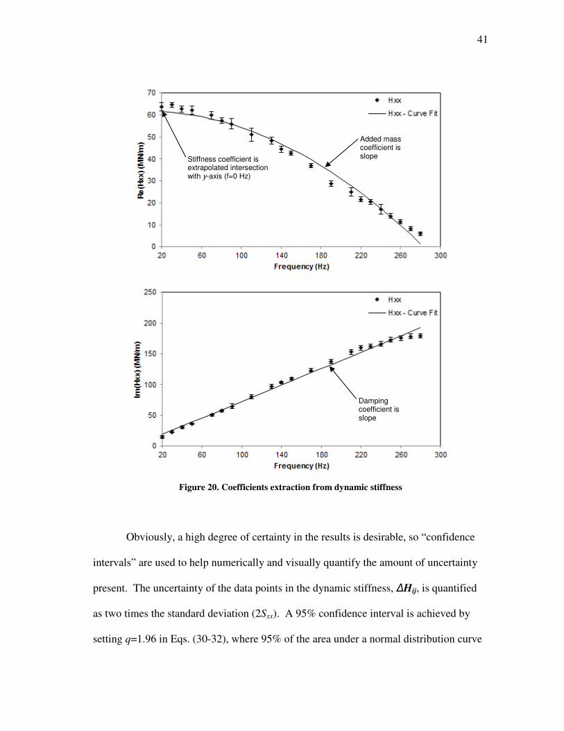
41
Figure 20. Coefficients extraction from dynamic stiffness
Obviously, a high degree of certainty in the results is desirable, so “confidence
intervals” are used to help numerically and visually quantify the amount of uncertainty
present. The uncertainty of the data points in the dynamic stiffness, ∆Hij, is quantified
as two times the standard deviation (2Sxx). A 95% confidence interval is achieved by
setting q=1.96 in Eqs. (30-32), where 95% of the area under a normal distribution curve
Damping coefficient is slope
Added mass coefficient is slope Stiffness coefficient is
extrapolated intersection with y-axis (f=0 Hz)
42
lies within approximately 1.96 standard deviations of the mean. The equations used to
calculate the uncertainties in the rotordynamic coefficients are:
+×=∆
xxD
ijS
x
NqK
22 1
σ (30)
xx
ijS
qC2σ
×=∆ (31)
xx
ijS
qM2σ
×=∆ (32)
( )
2ˆ 1
2
2
−
−
=∑
=
D
N
i
ii
N
yy
σ (33)
2
1
2 xNxS D
N
i
ixx −=∑=
(34)
Note that the values of the excitation frequency points and average, ix and x
respectively, in the above equations depend on what coefficient is being determined.
Rather, ix and x refer to Ω2 for the stiffness and added mass coefficients, and to Ω for
the damping coefficients.
Non-Dimensionalization of Rotordynamic Coefficients
Non-dimensionalization of rotordynamic coefficients is sometimes useful for
comparing similar bearings. The following non-dimensional stiffness ( ijK ), damping
( ijC ), and added mass ( ijM ) terms are defined, where CP is the radial pad clearance, ω is
43
the running speed, W is the static load, and Kij, Cij, and Mij are the dimensional stiffness,
damping, and added mass coefficients, respectively.
ij
P
ij KW
CK = (35)
ij
P
ij CW
CC
ω= (36)
ij
P
ij MW
CM
2ω= (37)
Whirl Frequency Ratio
Whirl frequency ratio (WFR) is a stability indicator originally introduced by
Lund [18]. WFR relates the natural frequency of a flexible rotor, supported at its ends
by identical bearings, to the onset speed of instability (OSI), or the limiting upper
operating speed of a bearing, as shown in Eq. (38). The equation shows that a low WFR
is indicative of a high OSI; in other words, the lower the WFR the higher the maximum
stable rotor running speed. For example, a bearing with a WFR of 0.25 would have an
OSI of four times the rotor natural frequency. Permanent stability is indicated by a WFR
of zero, meaning that the bearing imposes no upper operating limit for the rotor.
WFR
OSIOSI
WFRrotornrotorn ,,
or ,Ω
=Ω
= (38)
Lund’s equation does not account for added-mass terms; however, San Andrés
[19] updated this equation. After some lengthy manipulations, San Andrés’ equation
reduces to the polynomial given in Eq. (39), where WFRa , WFRb , and WFRc are the terms
defined below and ijK , ijC , and ijM are the non-dimensionalized bearing coefficients
44
defined previously. Note that removing the cross-coupled added mass terms reduces the
polynomial to that of Lund’s equation.
024 =++ WFRWFRWFR cWFRbWFRa (39)
( ) ( )eqyyxxyxxyyyxxeqWFR MMMMMMMMa +−−+= 2 (40)
( ) ( )yxxyxyyxyxxyyyxxxxyyyyxx
eqeqeqyyxxeqyyxxWFR
CCMKMKCCMKMK
MKKMMMKKb
+++−−−
+−+++=
2 (41)
( ) eqyyxxeqyxyxyyxxWFR KKKKKKKKc +−+−=2
(42)
yyxx
xyyxyxxyxxyyyyxxeq
CC
MCMCMCMCM
+
−−+= (43)
yyxx
xyyxyxxyxxyyyyxxeq
CC
KCKCKCKCK
+
−−+= (44)
Realizing that San Andrés’ equation is a fourth order polynomial, two types of
solutions are possible – real positive values and their negatives, and purely imaginary
values and their complex conjugates. If a real positive root is found, that number is the
WFR; however, if all roots are purely imaginary or equal to zero, the WFR for that
condition is zero.
45
5. ANALYTICAL PROCEDURE
Rotordynamics software is available to provide predictions for some of the
parameters obtained through testing for the flexure-pivot-pad bearing. Developed at the
Texas A&M Turbomachinery Laboratory, the XLTRC2-XLTFPBrg Rotordynamics
Suite© is used to predict rotordynamic coefficients, power loss, and eccentricity for the
FPJB. A brief description of the program and its modeling options follows.
XLTRC2-XLTFPBrg Rotordynamics Suite©
The XLTRC2-XLTFPBrg© software predicts rotordynamic coefficients, power
loss, and eccentricity for the FPJB at all shaft speed and static load conditions tested.
The code is based on San Andrès [20] and uses a bulk flow model that includes axial and
circumferential momentum, mass, and energy conservation. Both laminar and turbulent
flows are modeled in the thin film region between the bearing pads and rotor. Temporal
and convective acceleration terms can be included. Temperature dependent functions
are used for the bulk lubricant density and viscosity. The model includes the effects of
pad rotational stiffness, damping, and inertia.
A perturbation analysis is used, in which small journal displacements are
imposed about the bearing center, to solve the momentum and continuity equations for
the flow fields including pressure and temperature. The fluid film forces and moments
on each pad are found by integration of the pressure field, which are used to determine
the stiffness and damping coefficients for the bearing. An iterative approach is needed
to find the journal static equilibrium coordinates and pad rotation angles which satisfy
the load and moment constraints, and a Newton-Raphson algorithm is used for quick
46
convergence. Perturbations and pad motions are assumed to occur at the same
frequency, as chosen by the user and selected as synchronous or non-synchronous in the
menu. A discussion of the primary modeling options in the software follows.
XLTRC2-XLTFPBrg Modeling Options
Pad Inertia, Rotational Stiffness, and Damping
The pad inertia, rotational stiffness, and damping values determined earlier in the
Preliminary Testing and Results section are used as inputs for the XLTFPBrg software.
Because two different rotational stiffness (1194, 1758 N.m/rad) values varying by 47%,
and a corresponding damping value of approximately 0.01 N.s.m/rad for both rotational
stiffnesses were found, both stiffnesses were modeled in the software. After testing, the
predicted coefficients using each pair of pad stiffness and damping values were
compared to the experimental results, which showed that the majority of results were
better predicted using the lower (experimentally obtained) pad rotational stiffness of
1194 N.m/rad. Therefore, all of the results presented later were obtained using the
experimental values as inputs in the prediction software.
Fluid Inertia
Fluid inertia is usually included when the operating speed is high. As an
exercise, the code was run both including and excluding fluid inertia. An error analysis
between the predicted and measured rotordynamic coefficients showed that 66% of the
direct coefficients (stiffness, damping, and added mass) were better predicted by
including the fluid inertia. In instances where the exclusion of fluid inertia provided
47
better results, usually only small differences existed between the predictions with and
without including fluid inertia. Hence, the effects of fluid inertia were included.
Thermal Analysis
The software has several thermal-analysis options. Based on the data measured
during testing and the required inputs for the software, the adiabatic journal and
adiabatic bearing option was chosen. This assumes that no heat is transferred to or from
the journal or bearing and that all heat is carried away from the bearing by the oil.
Although the bearing and shaft were observed to warm up during testing, based on their
estimated temperatures and the temperature rise of the oil the rate of heat transfer was
assumed negligible.
Oil-Mixing Parameter
The thermal mixing coefficient λ is defined in Eq. (45) and represents the amount
of hot oil carry over between adjacent pads, where upQ& and downQ& are the upstream and
downstream flows, and Tup and Tdown are the upstream and downstream temperatures,
respectively. The value of the mixing coefficient normally ranges from 0.6 to 0.9 [21];
λ=0.65 was used in all software predictions.
upupplyplyinletdown TQTQTQ &&& λ+= supsup (45)
XLTFPBrg Chosen Input Parameters
Figures 21 and 22 show the XLTFPBrg software input and output screens,
respectively. All of the entries (gray highlighted cells) in both figures remain unchanged
48
except for those accounting for rotor speed and static load, which are changed to match
the nominal experimental test conditions. Note that the loading in Fig. 22 is described as
a force (N) rather than a unit loading (kPa) as used later in the results sections. The
excitation frequencies are essentially the same frequencies (20-320 Hz) used in testing,
but converted to cpm.
The theoretical stiffness and added mass coefficients are reduced in a similar
manner as those shown in the experimental dynamic data reduction procedures. Because
of the relative linearity of the stiffness curves, choosing the stiffness coefficient to be the
y-intercept of the second order curve fit of the stiffness values yields stiffness
coefficients that are less than those actually predicted by the software. Therefore, the
stiffness coefficients are taken as the stiffnesses predicted at 60 rpm, or 1 Hz. Added
mass coefficients are still determined as the second-order curve fit, as outlined in the
dynamic data reduction procedures.
The software produces damping coefficients at various frequencies, rather than
the coefficient as the slope of the imaginary portion of the dynamic stiffness versus
excitation frequency, as in the experiments. Experiments indicated frequency
independent damping, and as a reasonable approximation, the predicted damping
coefficients are evaluated at running speed (synchronous).
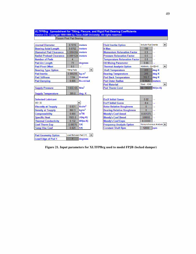
49
Figure 21. Input parameters for XLTFPBrg used to model FPJB (locked damper)
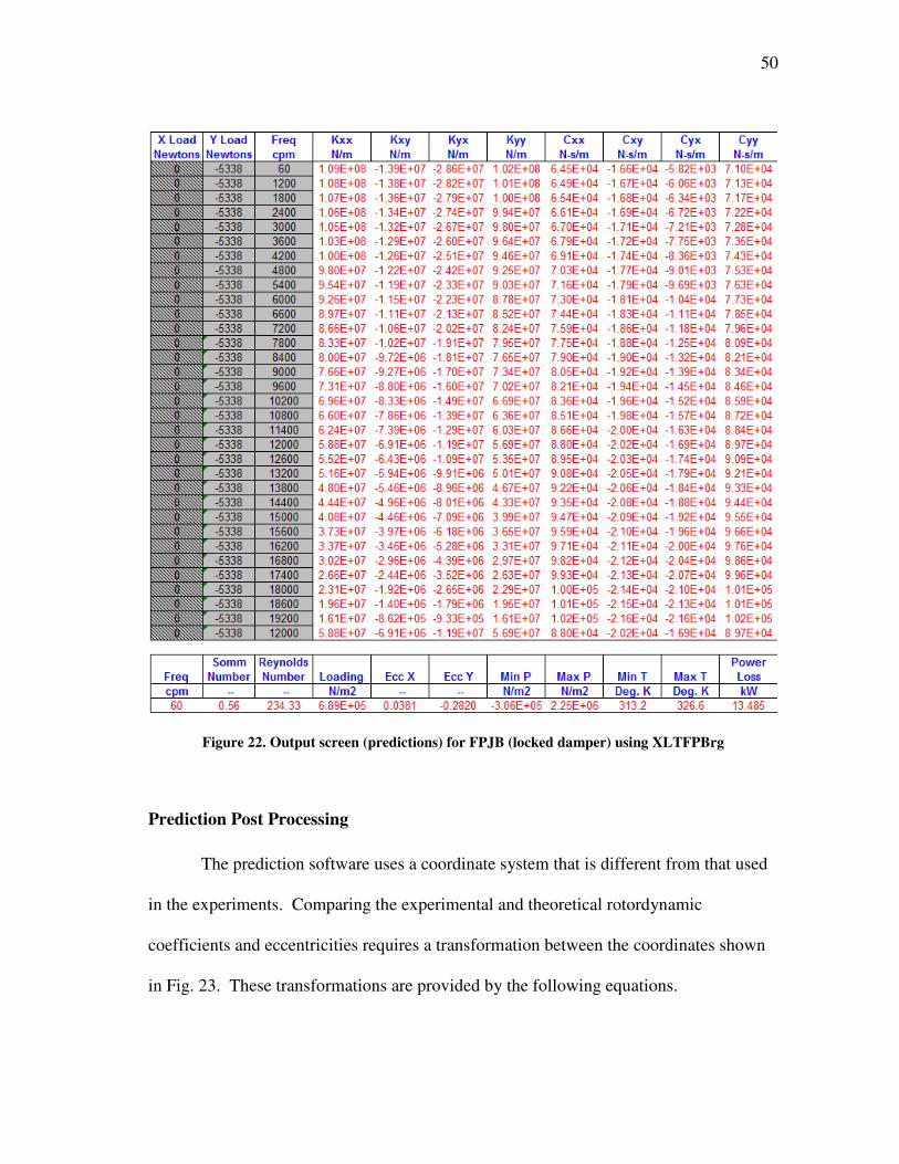
50
Figure 22. Output screen (predictions) for FPJB (locked damper) using XLTFPBrg
Prediction Post Processing
The prediction software uses a coordinate system that is different from that used
in the experiments. Comparing the experimental and theoretical rotordynamic
coefficients and eccentricities requires a transformation between the coordinates shown
in Fig. 23. These transformations are provided by the following equations.
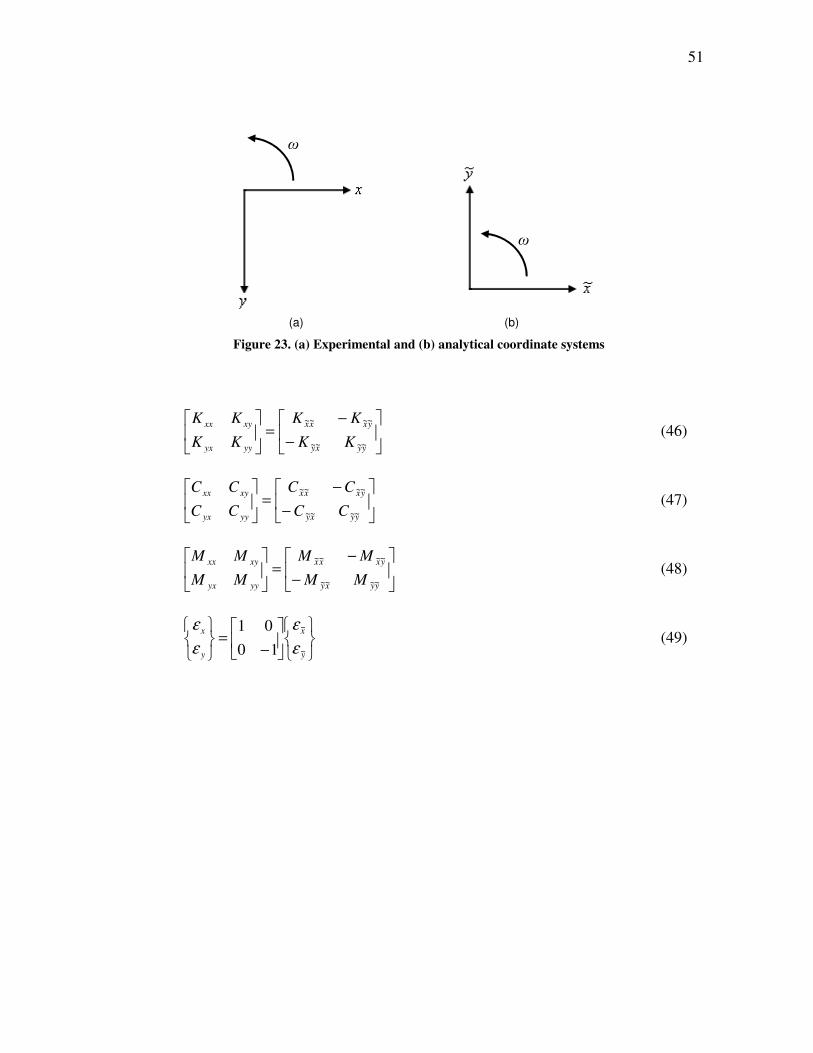
51
Figure 23. (a) Experimental and (b) analytical coordinate systems
−
−=
yyxy
yxxx
yyyx
xyxx
KK
KK
KK
KK
~~~~
~~~~
(46)
−
−=
yyxy
yxxx
yyyx
xyxx
CC
CC
CC
CC
~~~~
~~~~
(47)
−
−=
yyxy
yxxx
yyyx
xyxx
MM
MM
MM
MM
~~~~
~~~~
(48)
−=
y
x
y
x
~
~
10
01
ε
ε
ε
ε (49)
ω
ω
(a) (b)
52
6. STATIC RESULTS: MEASURED AND PREDICTED
Static performance characteristics are those occurring with the rotor at its
stationary equilibrium position and at steady state conditions. This section presents
representative measured static results for both bearing configurations, and predictions for
the FPJB (locked damper) obtained using the XLTRC2-XLTFPBrg© software described
in the previous section. Parameters discussed include eccentricity, attitude angle, pad
metal temperatures, squeeze film land metal temperatures, and power loss. All tests are
conducted using ISO VG32 turbine oil and occur at an oil flow rate of 45 L/min (12
gpm).
Eccentricity and Attitude Angle
Journal loci plots show measured and predicted eccentricity results for the FPJB
and damper-bearing in Fig. 24; the damper-bearing predictions use the FPJB predictions
with an added y-direction deflection calculated using the known static load and damper
structural stiffness. As expected, increasing the static load on the bearing causes a
displacement in the direction of the load, εy, except for the FPJB in (c) and (d), where εy
remains approximately constant or actually decreases slightly between certain loads.
Similarly, while some displacement in the x-direction εx is expected due to cross-coupled
forces, some of the conditions appear excessive. Alternating static and dynamic tests at
each condition (with the possibility of some static lag in the shaker heads), rather than
performing all the static tests for a given running speed and then all of the dynamic tests,
53
is the suspected cause of this. At higher loads, however, the eccentricities typically
move closer to the loaded axis as expected.
Experiments were conducted for shaft speeds from 4000-12000 rpm and to a
maximum static load of 862 kPa, except for 4000 rpm where rubbing was suspected due
to an audible “tapping” during dynamic testing. Extrapolation of the eccentricity in Fig.
24(a) after the incident indicates that rubbing is clearly a concern at 862 kPa, as the rotor
would be very close to the limit of the bearing clearance, CB = 152.4 µm (0.006 in), and
likely at or beyond the clearance during dynamic testing. This is an important lesson of
how bearing eccentricity must be considered for anticipated loading. No significant
damage to the bearing was noted after testing.
The software under predicts the eccentricity of the FPJB. The software also
predicts that, under no load, the bearing is concentric with the rotor, while all
measurements show there to be some eccentricity in the x-direction possibly due to an
imperfect bearing centering, residual displacement in the shakers left over from previous
tests, or slightly different pad preloads due to machining tolerances. The predicted
results better follow the expected trend of the bearing center moving closer to the loaded
axis with increasing load. This might also be explained by an imperfect bearing
centering process or a small static lag in the x-direction hydraulic shaker imparting a
slight load in that direction.
The eccentricities in Fig. 24 for the damper-bearing confirm that this
configuration is much softer than the FPJB alone. While the FPJB displacements tend to
get closer together with increasing load (indicating the fluid film is stiffening), the
54
damper-bearing displacement increments are almost equal regardless of load. This is a
result of the nearly constant stiffness due to the series bearing-damper stiffness. The
significantly lower series stiffness of the damper-bearing is evident in eccentricities that
are on the order of two times the locked damper case. Note that the added flexibility of
the damper allows the journal eccentricity for the damper-bearing to extend beyond the
bearing clearance; the clearance of the damper is not shown for clarity.
Eccentricity predictions for the damper-bearing are provided using the
predictions for the FPJB and adding a y-direction deflection equal to the static load
divided by the damper structural stiffness. While the measurements show a significant
x-direction eccentricity component and an initial y-direction component, this is not
predicted. There are several possible reasons for this, such as an imperfectly centered
bearing, unequal pad preloads due to tolerances, ect. If the damper-bearing eccentricity
measurements were moved so that the zero load data points matched with the
predictions, the predicted eccentricities at higher loads match very well.
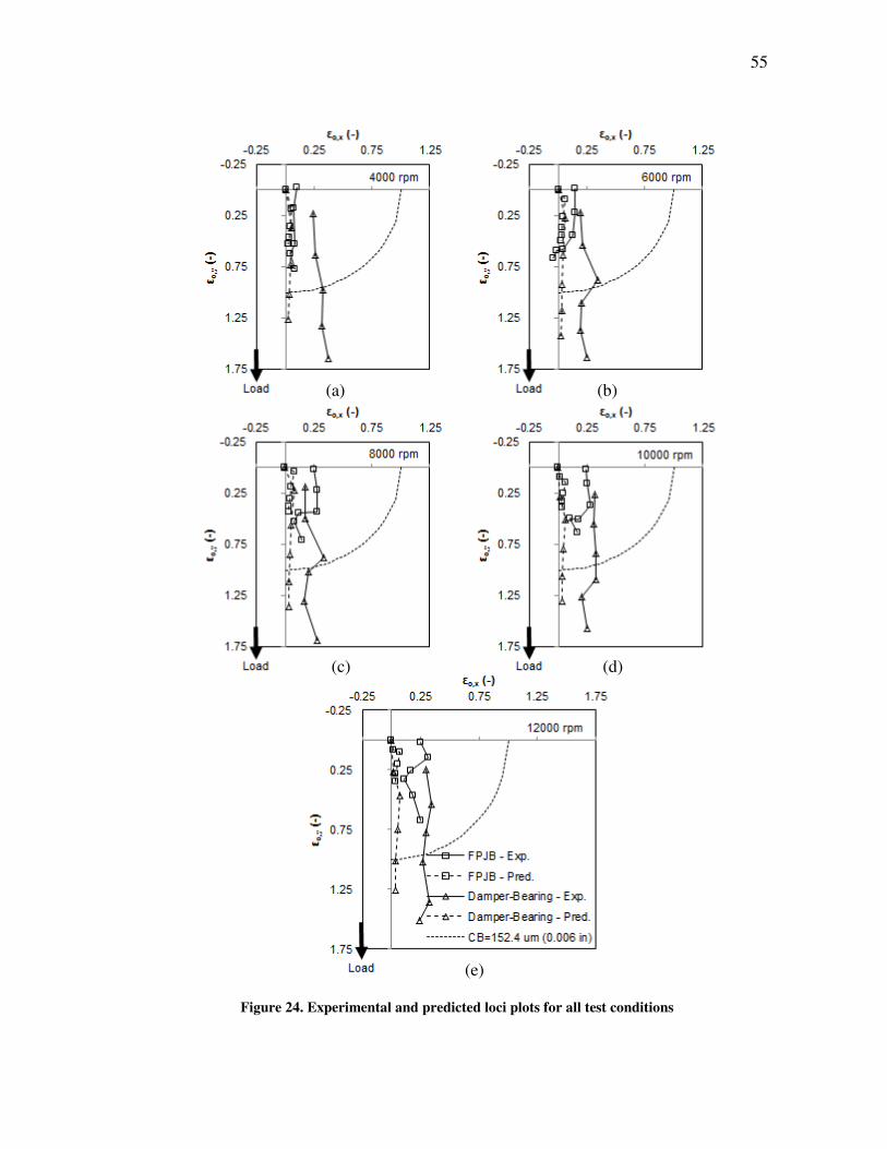
55
Figure 24. Experimental and predicted loci plots for all test conditions
(a) (b)
(c) (d)
(e)
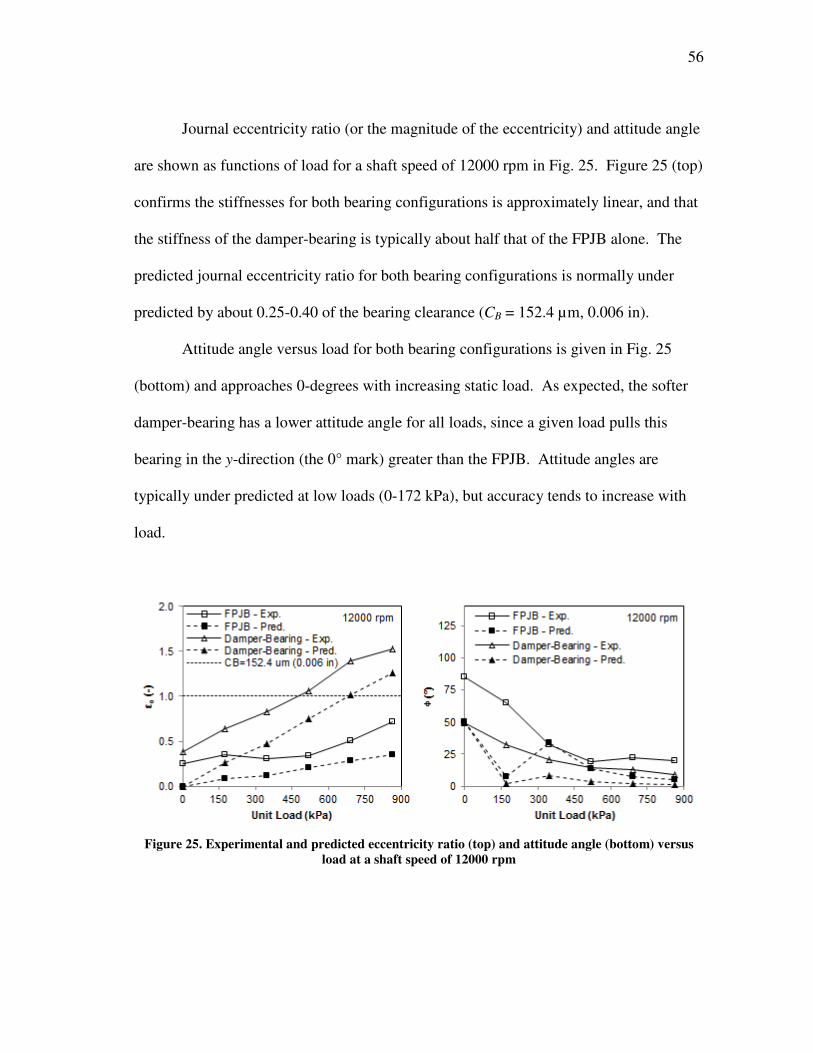
56
Journal eccentricity ratio (or the magnitude of the eccentricity) and attitude angle
are shown as functions of load for a shaft speed of 12000 rpm in Fig. 25. Figure 25 (top)
confirms the stiffnesses for both bearing configurations is approximately linear, and that
the stiffness of the damper-bearing is typically about half that of the FPJB alone. The
predicted journal eccentricity ratio for both bearing configurations is normally under
predicted by about 0.25-0.40 of the bearing clearance (CB = 152.4 µm, 0.006 in).
Attitude angle versus load for both bearing configurations is given in Fig. 25
(bottom) and approaches 0-degrees with increasing static load. As expected, the softer
damper-bearing has a lower attitude angle for all loads, since a given load pulls this
bearing in the y-direction (the 0° mark) greater than the FPJB. Attitude angles are
typically under predicted at low loads (0-172 kPa), but accuracy tends to increase with
load.
Figure 25. Experimental and predicted eccentricity ratio (top) and attitude angle (bottom) versus
load at a shaft speed of 12000 rpm
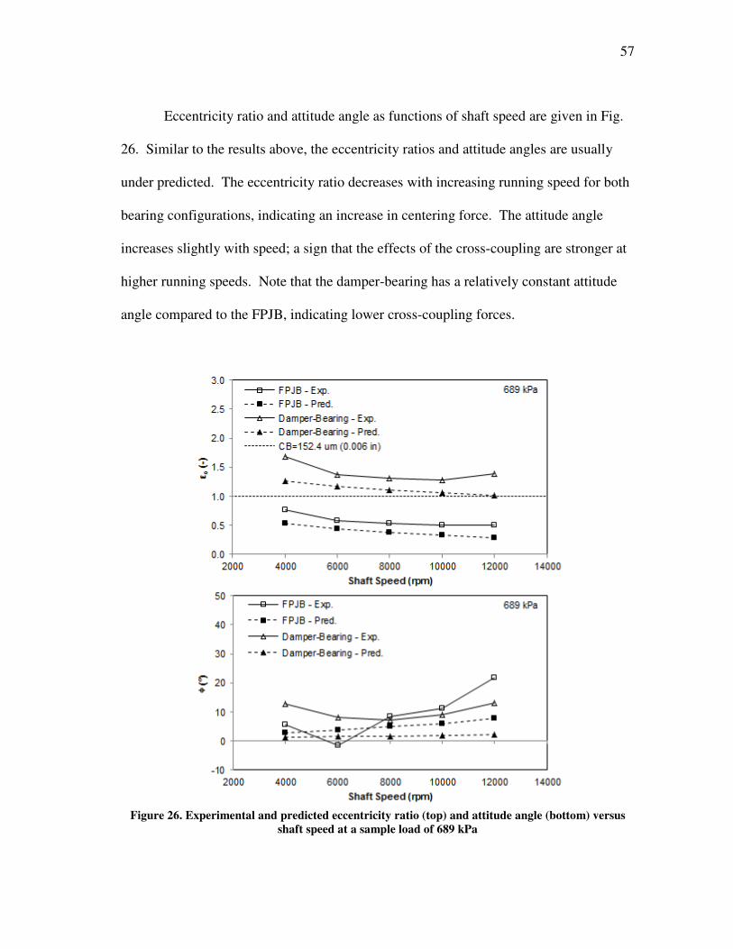
57
Eccentricity ratio and attitude angle as functions of shaft speed are given in Fig.
26. Similar to the results above, the eccentricity ratios and attitude angles are usually
under predicted. The eccentricity ratio decreases with increasing running speed for both
bearing configurations, indicating an increase in centering force. The attitude angle
increases slightly with speed; a sign that the effects of the cross-coupling are stronger at
higher running speeds. Note that the damper-bearing has a relatively constant attitude
angle compared to the FPJB, indicating lower cross-coupling forces.
Figure 26. Experimental and predicted eccentricity ratio (top) and attitude angle (bottom) versus
shaft speed at a sample load of 689 kPa

58
Pad Metal and Squeeze Film Land Metal Temperatures
The temperature distribution in a bearing is analogous to the pressure
distribution, which is useful for understanding the behavior of a bearing. This pressure
distribution is dependent on lubricant properties, which are temperature dependent and
therefore vary throughout the bearing film lands. The temperature distribution is key to
understanding the pressure distribution without directly measuring pressures, since the
high pressures in lubricant film increase the temperatures. Thermocouples located near
the inside surface of the pads are used for measuring the pad metal temperatures and
give an indication of the lubricant temperature distribution within the bearing lands.
Similarly, knowledge of the squeeze film land temperatures can help better understand
of heat transfer in the bearing, and temperatures at two different axial positions can help
identify misalignment.
Figure 27 shows the fourteen thermocouple locations used for measuring the pad
metal temperatures, located approximately 3.175 mm (0.125 in) from the pad surface. A
similar arrangement of eight thermocouples is used to measure temperatures along the
squeeze film land, except that the devices are paired at four different circumferential
locations with one each on the drive end (DE) and non-drive end (NDE), as shown in
Fig. 27 and 28.

59
Figure 27. Bearing and squeeze film land thermocouple locations
Figure 28. Squeeze film land thermocouple DE and NDE locations
Measured pad metal temperatures for both bearing configurations and their
corresponding oil supply temperatures are given at different loads in Fig. 29 for a sample
shaft speed of 4000 rpm. The static load is applied between pads 1 and 2, so the peak
pad metal temperatures occurring on these pads is expected. Supply oil injected between
the pads is shown to have a significant cooling effect on the downstream pads and a
DRIVE END NON-DRIVE END
NON-DRIVE END
DRIVE END 40.64 TYP
21.59 TYP
PAD BACK PAD
END SEAL BOTH SIDES
SQUEEZE FILM LAND
60
slight effect on the upstream pads, as evidenced by the temperature drops at these
locations. Note that the leading edge temperatures are all greater than the oil supply
temperatures, indicating hot oil carry over and mixing from the previous pad.
Observation of the pad metal temperatures for both bearing configurations
suggests a linear temperature increase with load, although this is not as obvious with the
damper-bearing due to the more variable oil supply temperatures shown in Fig. 29.
Although attempts were made to keep the supply oil temperature constant, warm
ambient conditions around the oil coolers resulted in sometimes varying temperatures.
The temperature distributions across the pads of the damper-bearing tend to be “flatter”
than those of the FPJB; rather, the temperature changes along the pad circumference are
less for the damper-bearing. Note the dashed line in Fig. 29, which is the oil supply
temperature used for the prediction software and is shown to be a reasonable
representation of average test conditions.
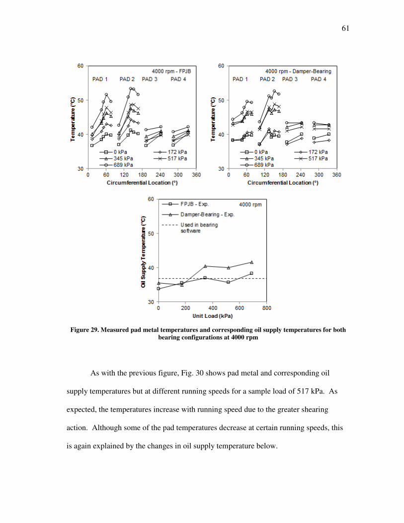
61
Figure 29. Measured pad metal temperatures and corresponding oil supply temperatures for both
bearing configurations at 4000 rpm
As with the previous figure, Fig. 30 shows pad metal and corresponding oil
supply temperatures but at different running speeds for a sample load of 517 kPa. As
expected, the temperatures increase with running speed due to the greater shearing
action. Although some of the pad temperatures decrease at certain running speeds, this
is again explained by the changes in oil supply temperature below.
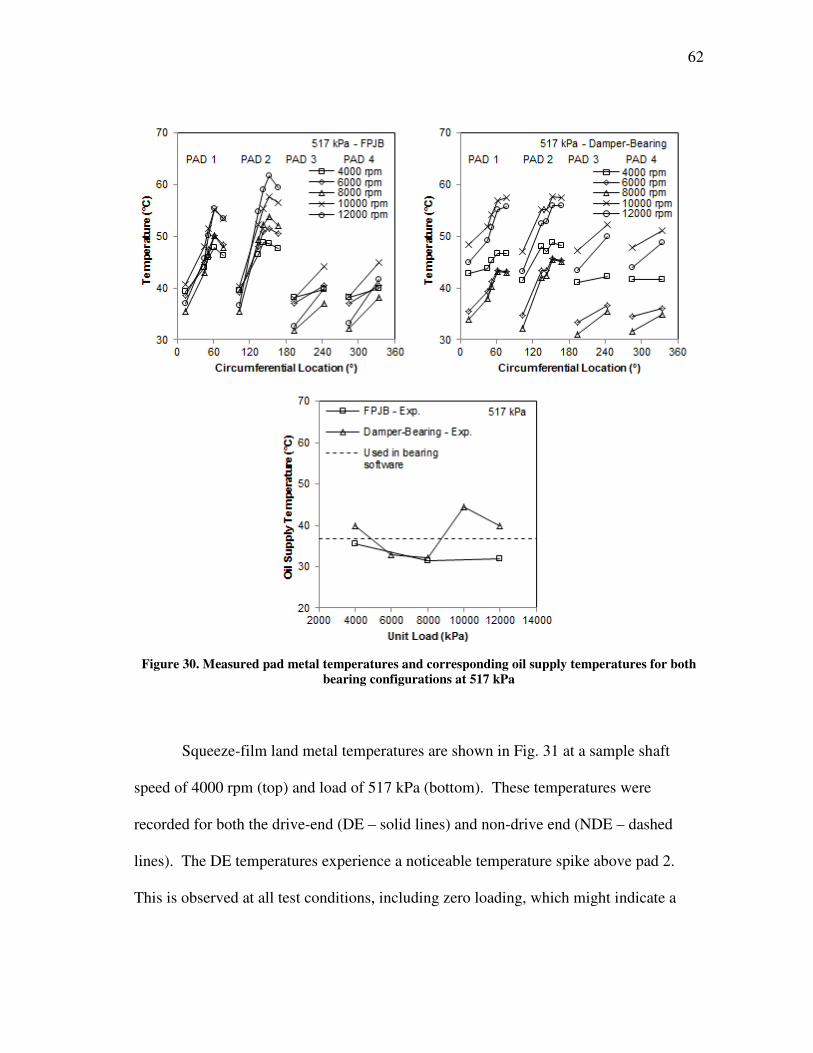
62
Figure 30. Measured pad metal temperatures and corresponding oil supply temperatures for both
bearing configurations at 517 kPa
Squeeze-film land metal temperatures are shown in Fig. 31 at a sample shaft
speed of 4000 rpm (top) and load of 517 kPa (bottom). These temperatures were
recorded for both the drive-end (DE – solid lines) and non-drive end (NDE – dashed
lines). The DE temperatures experience a noticeable temperature spike above pad 2.
This is observed at all test conditions, including zero loading, which might indicate a
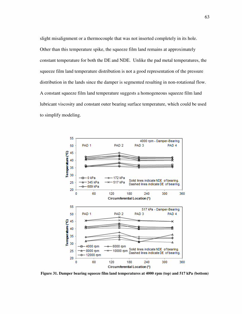
63
slight misalignment or a thermocouple that was not inserted completely in its hole.
Other than this temperature spike, the squeeze film land remains at approximately
constant temperature for both the DE and NDE. Unlike the pad metal temperatures, the
squeeze film land temperature distribution is not a good representation of the pressure
distribution in the lands since the damper is segmented resulting in non-rotational flow.
A constant squeeze film land temperature suggests a homogeneous squeeze film land
lubricant viscosity and constant outer bearing surface temperature, which could be used
to simplify modeling.
Figure 31. Damper bearing squeeze film land temperatures at 4000 rpm (top) and 517 kPa (bottom)
64
Estimated Power Loss
Power loss in bearings is important because it affects machine efficiency and
operating cost. Since the test rig is not setup to measure the drag torque, the power loss
is instead estimated using the temperature dependent specific heat capacity of the oil and
the measured inlet and average outlet oil temperatures, described earlier in Section 4.
The estimated power loss for both bearing configurations is shown in Fig. 32 at
different loads and shaft speeds on the left and the corresponding temperature rise on the
right. At lower shaft speeds, the damper-bearing appears to yield lower power losses
than with the FPJB alone. However, at higher running speeds the results for both
configurations seem to converge. A similar trend is apparent viewing the power loss
versus shaft speed for the two sample loads shown. Power loss for the FPJB is typically
under predicted by about 2 kW, resulting in errors of up to 62% at 4000 rpm and
decreasing with increased shaft speed to less than 16% at 12000 rpm. Where the
experimental trends are apparent (i.e. smooth curves), the predictions do a good job of
following those trends. While the measured temperature rises are often erratic, when
used with the temperature dependent densities and specific heats they produce almost
constant power loss values.
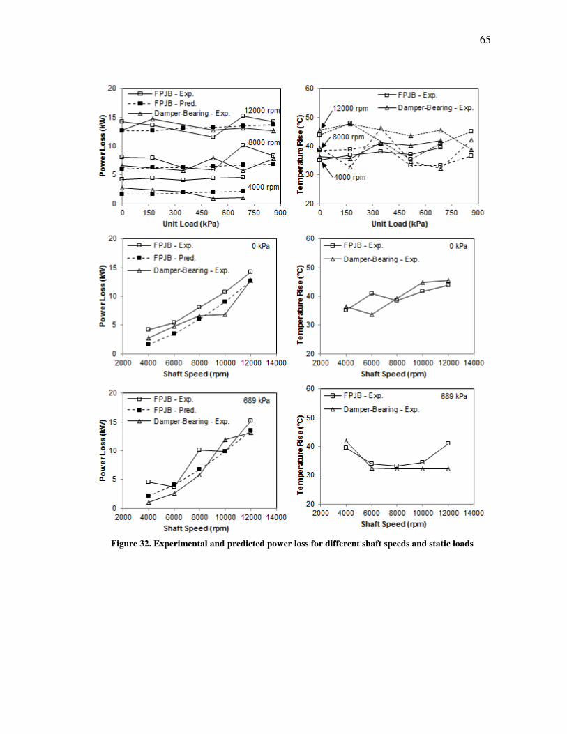
65
Figure 32. Experimental and predicted power loss for different shaft speeds and static loads

66
7. MEASURED AND PREDICTED MULTI-FREQUENCY RESULTS
This section details the dynamic stiffness coefficients and the derived
rotordynamic coefficients for the test bearing. Measured and predicted data are provided
for the FPJB, and measured data only are provided for the damper-bearing. Whirl
frequency ratio (WFR) as a stability indicator is also presented. Results for both bearing
configurations are presented together to gauge the effect of the squeeze film damper.
Finally, non-dimensionalized rotordynamic coefficients for the locked damper bearing
are compared to those obtained by Al-Ghasem [6] on a similar bearing to verify results
and to see how effective non-dimensionalization using the Sommerfeld number is.
Baseline Data
Dynamic tests are used to measure rotordynamic coefficients for the FPJB and
damper bearing. Due to the design of the test rig, before the dynamic tests are
performed, “baseline” tests are conducted for each bearing configuration at zero rotor
speed, zero load, and no oil (dry bearing). The baseline tests account for external
factors, such as the stiffness of the pitch stabilizers, stiffness of the unused hydraulic
shaker, and the mass of the bearing and bearing housing. These baseline dynamic
stiffnesses are subtracted from each subsequent dynamic test, so that only effects of the
fluid film bearing are determined.
Figures 33 and 34 show the baseline Re(Hij) and Im(Hij) coefficients,
respectively, for the FPJB (left) and damper bearing (right); the direct stiffnesses are
shown at the top and cross-coupled are on the bottom of each figure. Data points
occurring at frequencies of multiples of 60 Hz and beyond 300 Hz are removed for
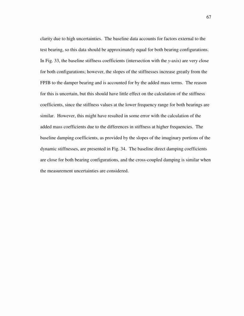
67
clarity due to high uncertainties. The baseline data accounts for factors external to the
test bearing, so this data should be approximately equal for both bearing configurations.
In Fig. 33, the baseline stiffness coefficients (intersection with the y-axis) are very close
for both configurations; however, the slopes of the stiffnesses increase greatly from the
FPJB to the damper bearing and is accounted for by the added mass terms. The reason
for this is uncertain, but this should have little effect on the calculation of the stiffness
coefficients, since the stiffness values at the lower frequency range for both bearings are
similar. However, this might have resulted in some error with the calculation of the
added mass coefficients due to the differences in stiffness at higher frequencies. The
baseline damping coefficients, as provided by the slopes of the imaginary portions of the
dynamic stiffnesses, are presented in Fig. 34. The baseline direct damping coefficients
are close for both bearing configurations, and the cross-coupled damping is similar when
the measurement uncertainties are considered.
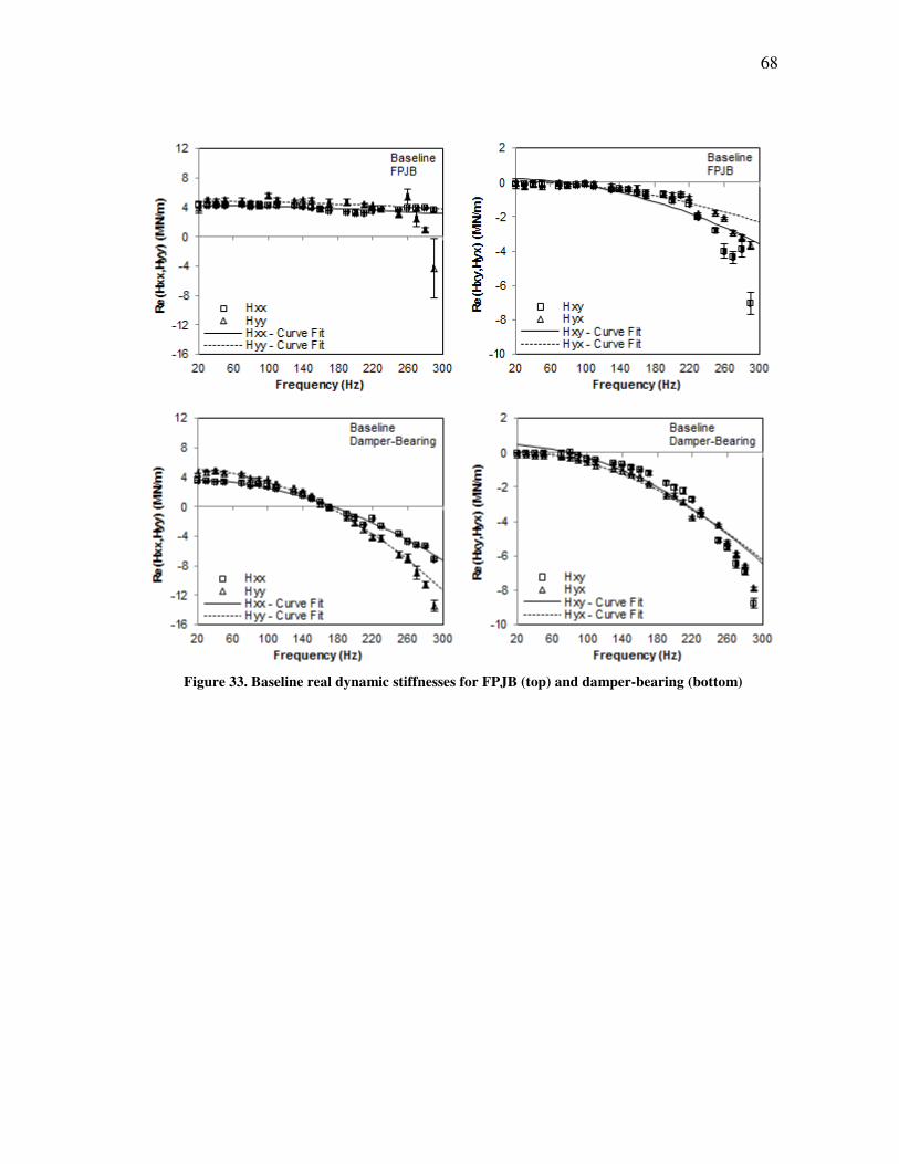
68
Figure 33. Baseline real dynamic stiffnesses for FPJB (top) and damper-bearing (bottom)
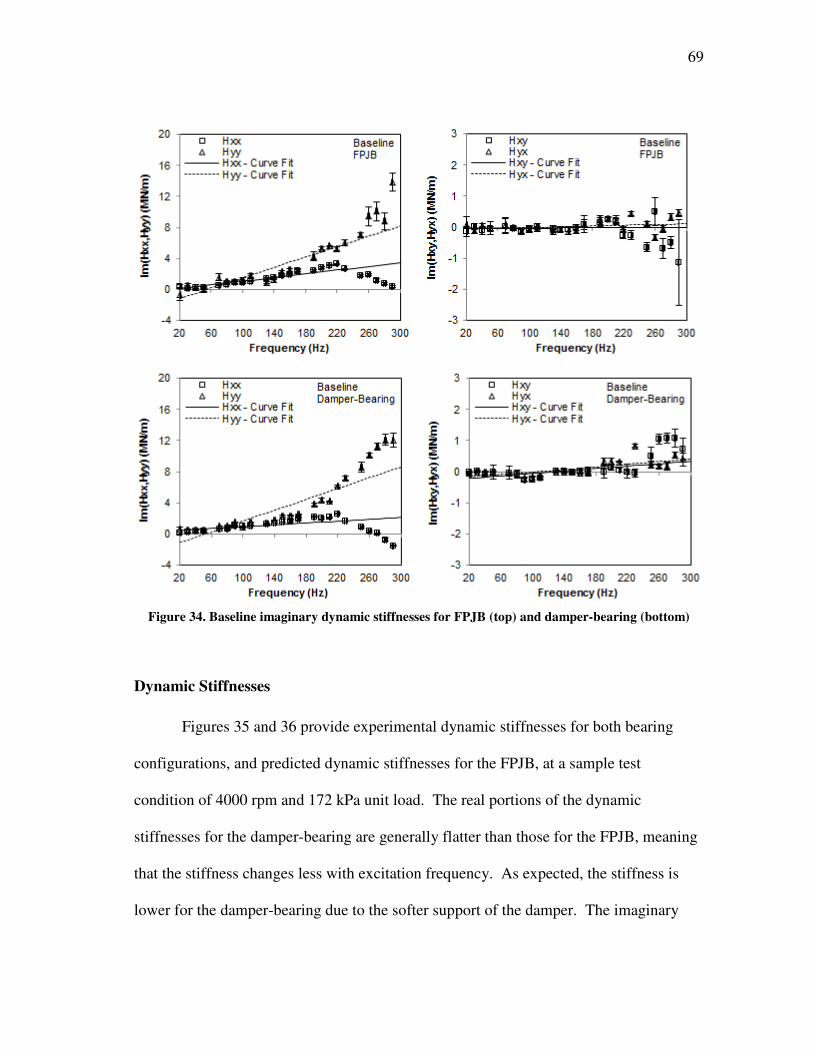
69
Figure 34. Baseline imaginary dynamic stiffnesses for FPJB (top) and damper-bearing (bottom)
Dynamic Stiffnesses
Figures 35 and 36 provide experimental dynamic stiffnesses for both bearing
configurations, and predicted dynamic stiffnesses for the FPJB, at a sample test
condition of 4000 rpm and 172 kPa unit load. The real portions of the dynamic
stiffnesses for the damper-bearing are generally flatter than those for the FPJB, meaning
that the stiffness changes less with excitation frequency. As expected, the stiffness is
lower for the damper-bearing due to the softer support of the damper. The imaginary
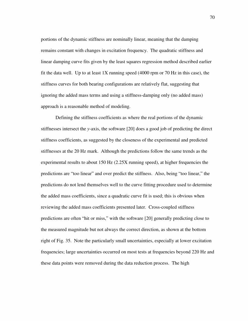
70
portions of the dynamic stiffness are nominally linear, meaning that the damping
remains constant with changes in excitation frequency. The quadratic stiffness and
linear damping curve fits given by the least squares regression method described earlier
fit the data well. Up to at least 1X running speed (4000 rpm or 70 Hz in this case), the
stiffness curves for both bearing configurations are relatively flat, suggesting that
ignoring the added mass terms and using a stiffness-damping only (no added mass)
approach is a reasonable method of modeling.
Defining the stiffness coefficients as where the real portions of the dynamic
stiffnesses intersect the y-axis, the software [20] does a good job of predicting the direct
stiffness coefficients, as suggested by the closeness of the experimental and predicted
stiffnesses at the 20 Hz mark. Although the predictions follow the same trends as the
experimental results to about 150 Hz (2.25X running speed), at higher frequencies the
predictions are “too linear” and over predict the stiffness. Also, being “too linear,” the
predictions do not lend themselves well to the curve fitting procedure used to determine
the added mass coefficients, since a quadratic curve fit is used; this is obvious when
reviewing the added mass coefficients presented later. Cross-coupled stiffness
predictions are often “hit or miss,” with the software [20] generally predicting close to
the measured magnitude but not always the correct direction, as shown at the bottom
right of Fig. 35. Note the particularly small uncertainties, especially at lower excitation
frequencies; large uncertainties occurred on most tests at frequencies beyond 220 Hz and
these data points were removed during the data reduction process. The high
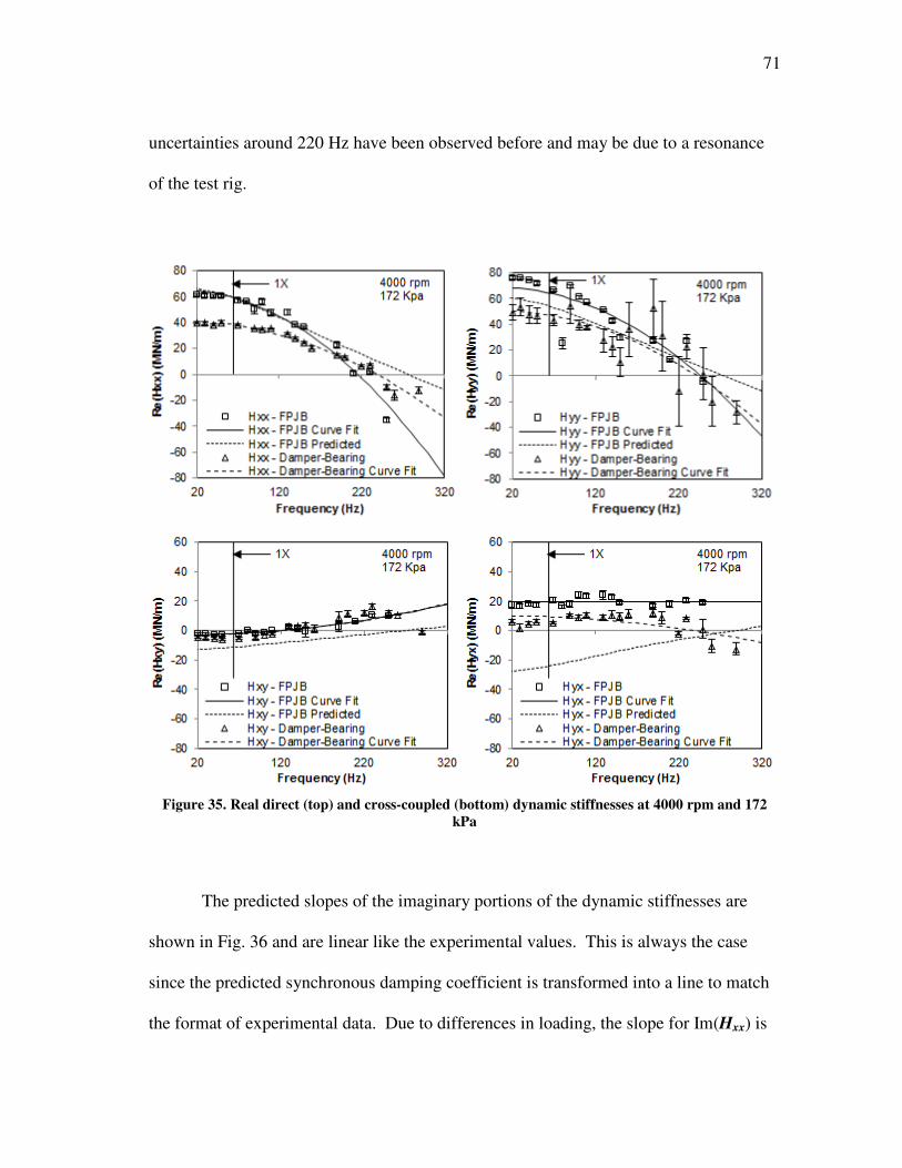
71
uncertainties around 220 Hz have been observed before and may be due to a resonance
of the test rig.
Figure 35. Real direct (top) and cross-coupled (bottom) dynamic stiffnesses at 4000 rpm and 172
kPa
The predicted slopes of the imaginary portions of the dynamic stiffnesses are
shown in Fig. 36 and are linear like the experimental values. This is always the case
since the predicted synchronous damping coefficient is transformed into a line to match
the format of experimental data. Due to differences in loading, the slope for Im(Hxx) is
72
normally over-predicted and the slope for Im(Hyy) is normally under-predicted. The
slopes of the cross-coupled terms Im(Hxy) and Im(Hyx) are often over-predicted in
magnitude and of opposite direction from the experimental values. This is more clearly
shown with the rotordynamic coefficients derived from this data presented in the next
section.
Figure 36. Imaginary direct (top) and cross-coupled (bottom) dynamic stiffnesses at 4000 rpm and
172 kPa
73
Rotordynamic Coefficients
This section presents the measured rotordynamic coefficients for both bearing
configurations, and predictions for the FPJB. The results for each bearing configuration
are shown on top of each other for comparison, and are then compared at the end of the
section to show the effect of the damper on the rotordynamic coefficients. Also, as an
exercise to increase confidence in the data obtained, non-dimensionalized data for the
FPJB (locked damper case) is compared to previous tests on a similar bearing. For
brevity, only representative data are presented, however, complete data can be found in
the appendix.
Measurements and Predictions
Figure 37 presents rotordynamic coefficients for the FPJB (left) and damper-
bearing (right), as well as predicted coefficients for the FPJB, at a sample shaft speed of
8000 rpm. For the FPJB, the direct stiffness and damping coefficients increase with
load, while the cross-coupled coefficients remain approximately constant. The added
mass coefficients remain constant with increasing load. The software [20] does a good
job of predicting the stiffness and damping coefficients, and a fair job of predicting
direct damping coefficients, but poorly predicts added mass coefficients, which is
expected since the dynamic stiffnesses predicted by the software are almost linear rather
than quadratic like those measured. Added mass coefficients are often under predicted,
and the wrong sign (+/-) is usually predicted for one or both of the cross-coupled terms.
For the damper-bearing, the stiffness, damping, and added mass coefficients
remain almost constant with increasing static load (except for the apparent damping
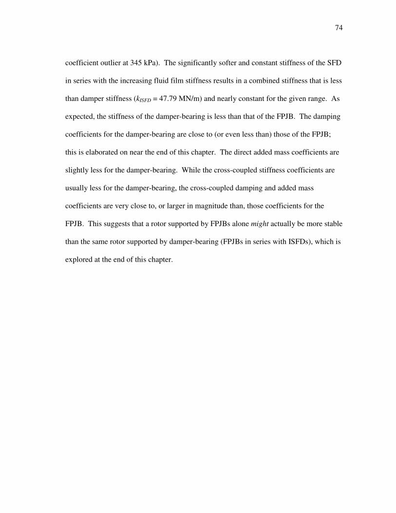
74
coefficient outlier at 345 kPa). The significantly softer and constant stiffness of the SFD
in series with the increasing fluid film stiffness results in a combined stiffness that is less
than damper stiffness (kISFD = 47.79 MN/m) and nearly constant for the given range. As
expected, the stiffness of the damper-bearing is less than that of the FPJB. The damping
coefficients for the damper-bearing are close to (or even less than) those of the FPJB;
this is elaborated on near the end of this chapter. The direct added mass coefficients are
slightly less for the damper-bearing. While the cross-coupled stiffness coefficients are
usually less for the damper-bearing, the cross-coupled damping and added mass
coefficients are very close to, or larger in magnitude than, those coefficients for the
FPJB. This suggests that a rotor supported by FPJBs alone might actually be more stable
than the same rotor supported by damper-bearing (FPJBs in series with ISFDs), which is
explored at the end of this chapter.
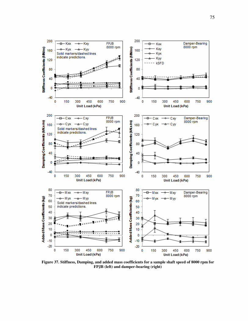
75
Figure 37. Stiffness, Damping, and added mass coefficients for a sample shaft speed of 8000 rpm for
FPJB (left) and damper-bearing (right)
76
Measured and predicted rotordynamic coefficients are presented as a function of
shaft speed in Fig. 38 at a sample load of 517 kPa for the FPJB (left), and measured
coefficients are presented for the damper-bearing (right). For the FPJB, the measured
direct stiffness coefficients increase with shaft speed, while the predictions for these
remain approximately constant. The cross-coupled stiffnesses are predicted well,
particularly at lower shaft speeds. The overall downward trend of the direct damping
coefficients and the flat trend of the cross-coupled damping coefficients are predicted,
and the magnitudes are predicted reasonably well. The added mass coefficients are
generally poorly predicted.
For the damper-bearing, the measured direct stiffness coefficients increase with
speed, but at a lesser rate than the FPJB due to the softer support of the SFD. Cross-
coupled stiffnesses remain relatively constant with speed, and are lower than those
measured for the FPJB. Damper-bearing test results show almost constant added mass
coefficients, regardless of shaft speed.
The quality of this experimental data might be described by both the uncertainty
(repeatability of the results) and the data curve fits. The multi-frequency test data for
both bearing configurations generally exhibits low uncertainty. Both bearing
configurations also yield similar quality curve fits, although those for the damper-
bearing are slightly better overall. Curve fits for direct coefficients are good, with R2
values typically greater than 0.9, while curve fits for cross-coupled coefficients vary but
often yield R2 values of 0.5 or more.
77
Figure 38. Stiffness, damping, and added mass coefficients for a sample load of 517 kPa for FPJB
(left) and damper-bearing (right)
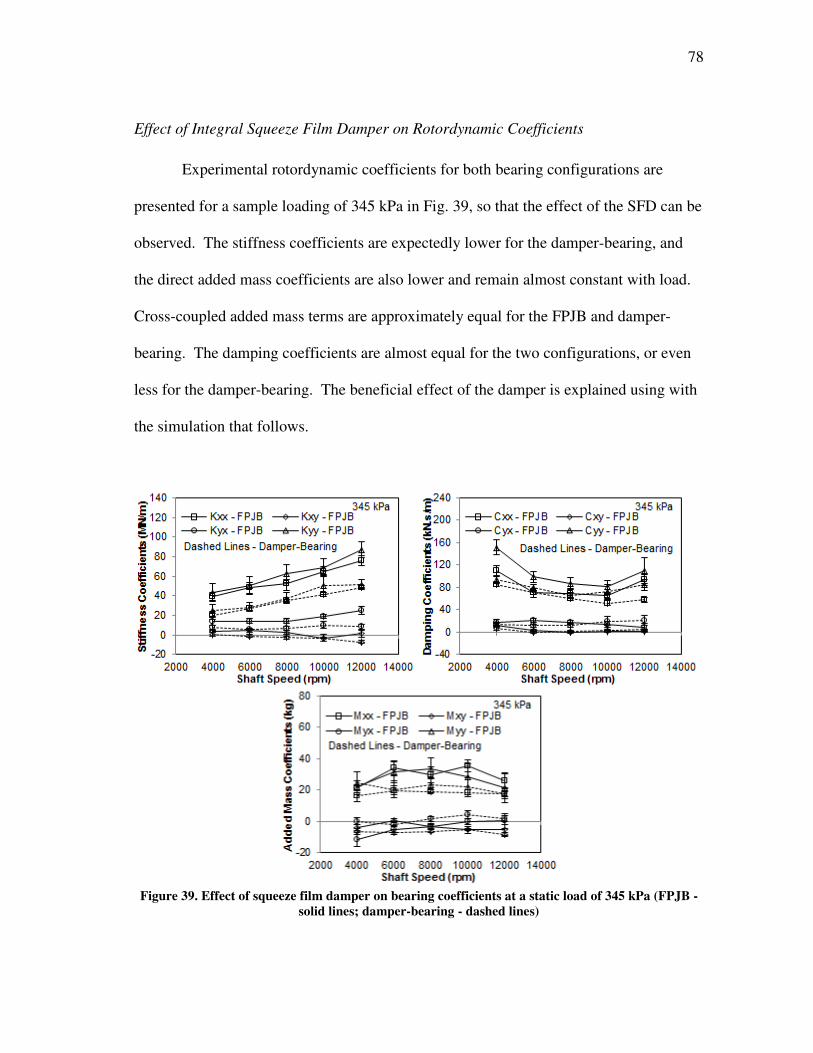
78
Effect of Integral Squeeze Film Damper on Rotordynamic Coefficients
Experimental rotordynamic coefficients for both bearing configurations are
presented for a sample loading of 345 kPa in Fig. 39, so that the effect of the SFD can be
observed. The stiffness coefficients are expectedly lower for the damper-bearing, and
the direct added mass coefficients are also lower and remain almost constant with load.
Cross-coupled added mass terms are approximately equal for the FPJB and damper-
bearing. The damping coefficients are almost equal for the two configurations, or even
less for the damper-bearing. The beneficial effect of the damper is explained using with
the simulation that follows.
Figure 39. Effect of squeeze film damper on bearing coefficients at a static load of 345 kPa (FPJB -
solid lines; damper-bearing - dashed lines)
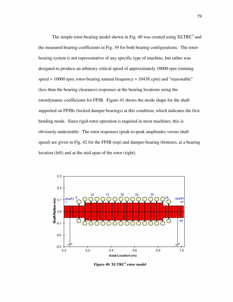
79
The simple rotor-bearing model shown in Fig. 40 was created using XLTRC2 and
the measured bearing coefficients in Fig. 39 for both bearing configurations. The rotor-
bearing system is not representative of any specific type of machine, but rather was
designed to produce an arbitrary critical speed of approximately 10000 rpm (running
speed = 10000 rpm; rotor-bearing natural frequency = 10438 cpm) and “reasonable”
(less than the bearing clearance) responses at the bearing locations using the
rotordynamic coefficients for FPJB. Figure 41 shows the mode shape for the shaft
supported on FPJBs (locked damper bearings) at this condition, which indicates the first
bending mode. Since rigid-rotor operation is required in most machines, this is
obviously undesirable. The rotor responses (peak-to-peak amplitudes versus shaft
speed) are given in Fig. 42 for the FPJB (top) and damper-bearing (bottom), at a bearing
location (left) and at the mid-span of the rotor (right).
Figure 40. XLTRC
2 rotor model
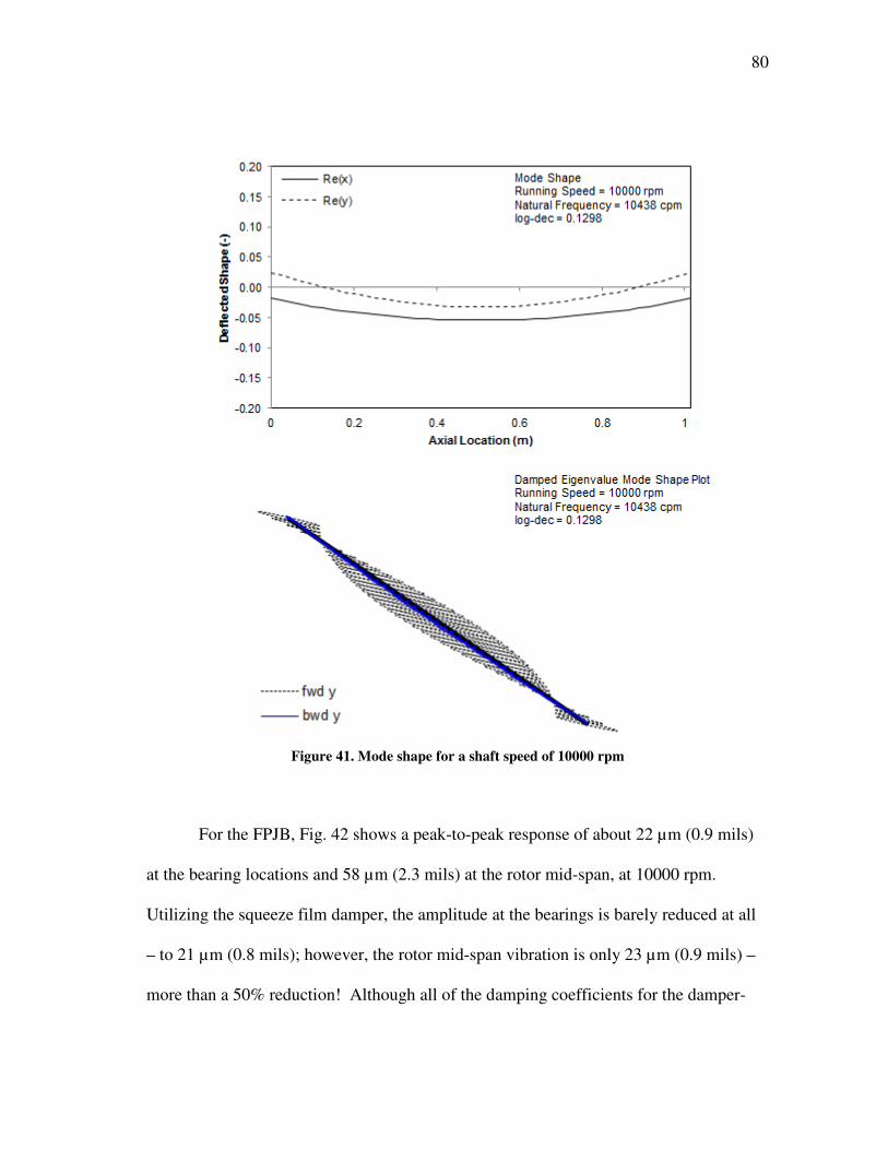
80
Figure 41. Mode shape for a shaft speed of 10000 rpm
For the FPJB, Fig. 42 shows a peak-to-peak response of about 22 µm (0.9 mils)
at the bearing locations and 58 µm (2.3 mils) at the rotor mid-span, at 10000 rpm.
Utilizing the squeeze film damper, the amplitude at the bearings is barely reduced at all
– to 21 µm (0.8 mils); however, the rotor mid-span vibration is only 23 µm (0.9 mils) –
more than a 50% reduction! Although all of the damping coefficients for the damper-
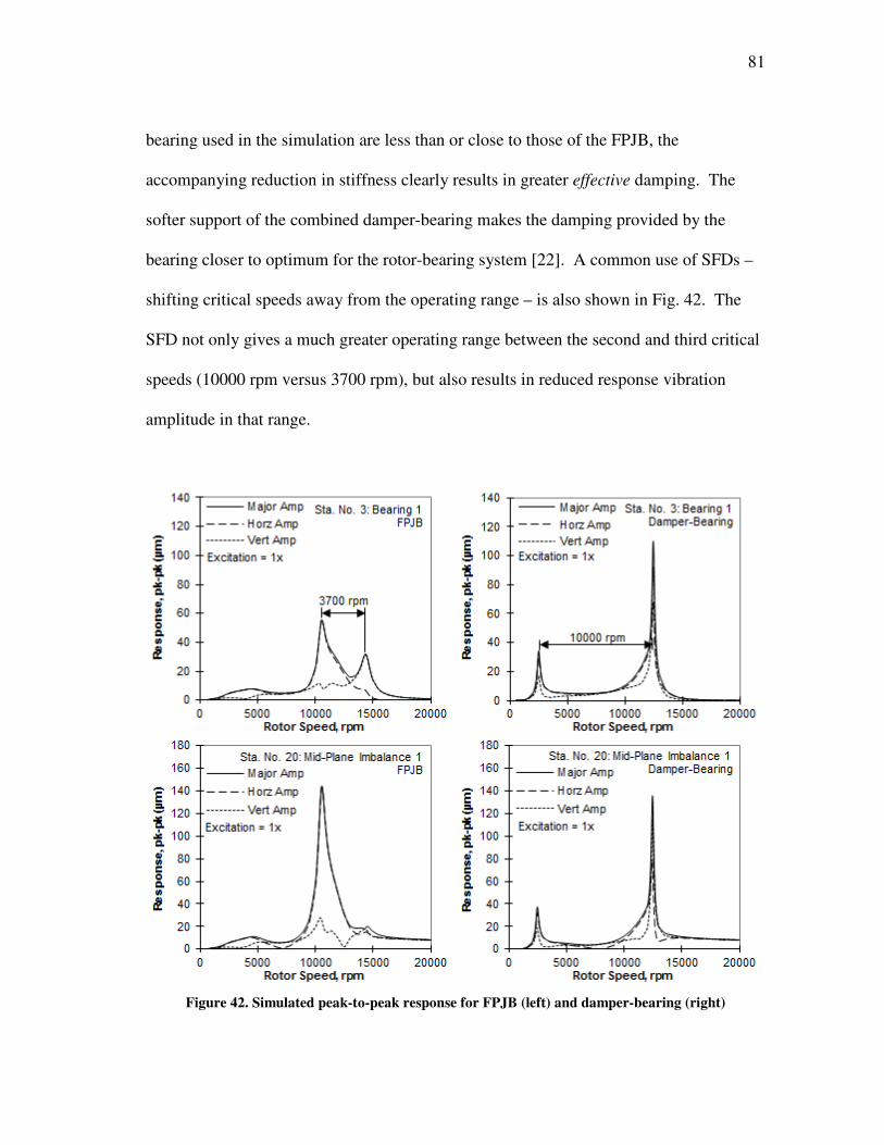
81
bearing used in the simulation are less than or close to those of the FPJB, the
accompanying reduction in stiffness clearly results in greater effective damping. The
softer support of the combined damper-bearing makes the damping provided by the
bearing closer to optimum for the rotor-bearing system [22]. A common use of SFDs –
shifting critical speeds away from the operating range – is also shown in Fig. 42. The
SFD not only gives a much greater operating range between the second and third critical
speeds (10000 rpm versus 3700 rpm), but also results in reduced response vibration
amplitude in that range.
Figure 42. Simulated peak-to-peak response for FPJB (left) and damper-bearing (right)
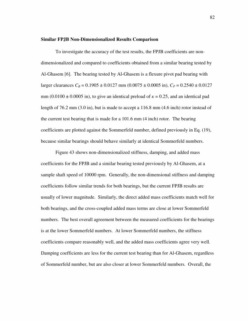
82
Similar FPJB Non-Dimensionalized Results Comparison
To investigate the accuracy of the test results, the FPJB coefficients are non-
dimensionalized and compared to coefficients obtained from a similar bearing tested by
Al-Ghasem [6]. The bearing tested by Al-Ghasem is a flexure pivot pad bearing with
larger clearances CB = 0.1905 ± 0.0127 mm (0.0075 ± 0.0005 in), CP = 0.2540 ± 0.0127
mm (0.0100 ± 0.0005 in), to give an identical preload of κ = 0.25, and an identical pad
length of 76.2 mm (3.0 in), but is made to accept a 116.8 mm (4.6 inch) rotor instead of
the current test bearing that is made for a 101.6 mm (4 inch) rotor. The bearing
coefficients are plotted against the Sommerfeld number, defined previously in Eq. (19),
because similar bearings should behave similarly at identical Sommerfeld numbers.
Figure 43 shows non-dimensionalized stiffness, damping, and added mass
coefficients for the FPJB and a similar bearing tested previously by Al-Ghasem, at a
sample shaft speed of 10000 rpm. Generally, the non-dimensional stiffness and damping
coefficients follow similar trends for both bearings, but the current FPJB results are
usually of lower magnitude. Similarly, the direct added mass coefficients match well for
both bearings, and the cross-coupled added mass terms are close at lower Sommerfeld
numbers. The best overall agreement between the measured coefficients for the bearings
is at the lower Sommerfeld numbers. At lower Sommerfeld numbers, the stiffness
coefficients compare reasonably well, and the added mass coefficients agree very well.
Damping coefficients are less for the current test bearing than for Al-Ghasem, regardless
of Sommerfeld number, but are also closer at lower Sommerfeld numbers. Overall, the
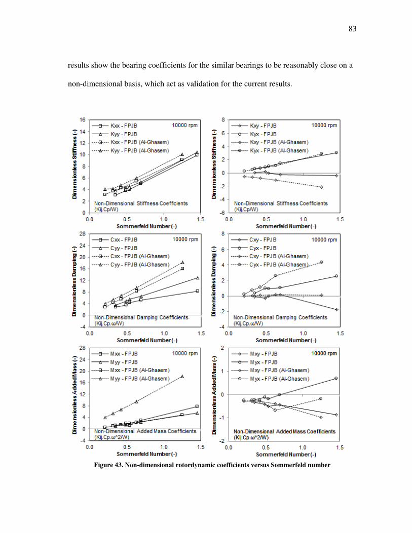
83
results show the bearing coefficients for the similar bearings to be reasonably close on a
non-dimensional basis, which act as validation for the current results.
Figure 43. Non-dimensional rotordynamic coefficients versus Sommerfeld number

84
Whirl Frequency Ratio (WFR)
The whirl frequency ratio (WFR) was calculated from the rotordynamic
coefficients to quantify the stability at the various test conditions. The WFRs indicate
infinite stability for both bearing configurations at many test conditions, including all
loads at 4000 rpm and 6000 rpm for FPJB and all but one load for the damper-bearing at
the same shaft speeds. Experimental and predicted WFRs, as well as corresponding
WFRs for the similar bearing tested by Al-Ghasem [6], are shown at sample shaft speeds
of 8000 rpm and 10000 rpm in Fig. 44. Using the rotordynamic coefficients predicted
following [20] for the FPJB, stability is normally over-predicted with WFRs equal to
zero, except at lower loads where the predictions normally over-predict the WFR
slightly. Unlike Al-Ghasem’s data which exhibits almost linear trends until the highest
loading, there is no obvious WFR trend in the current results for either bearing
configuration. However, the WFRs for both current bearing configurations are almost
always lower than those found by Al-Ghasem.
Whirl frequency ratio versus shaft speed is also shown in Fig. 44, for sample unit
loads of 172 kPa and 689 kPa. Increases in WFR typically accompany increases in shaft
speed for a given load, although it has zero magnitude at lower speeds in the given
examples. In cases where the predicted WFRs for the FPJB are non-zero, such as 0 kPa
at all shaft speeds and 172 kPa at 10000 rpm, the WFR is almost always over-predicted,
as illustrated below. As stated above, the WFRs for Al-Ghasem’s data are normally
much higher than those measured in the current experiments, but still do not exceed 0.2
for the data presented.
85
Figure 44. WFR at different static loads and shaft speeds
The maximum experimental WFR under the test conditions occurred at 12000
rpm and was 0.13 and 0.11 for the FPJB and damper-bearing, respectively, while the
maximum prediction for the FPJB was 0.25 and occurred at 4000 rpm. While the FPJB
has a higher maximum WFR, interestingly, the damper-bearing experiences a
significantly greater number of instances of non-zero WFRs from 8000-12000 rpm (six
non-zero WFRs for the FPJB; fifteen non-zero WFRs for the damper-bearing).
Regardless, the WFR remained low for both bearing configurations throughout all tests.
86
For example, the maximum WFR of 0.13 corresponds to an onset speed of instability
(OSI) of 7.7X the rotor natural frequency. Note that while conventional tilting pad
bearings have WFRs = 0 due to very low or non-existent cross-coupling, flexure-pivot-
pad journal bearings normally have a low WFR due to the cross-coupling present
because of the pivot stiffness.
As a side note, while WFR calculations were performed both excluding and
included the added mass term (Lund [18] and San Andrès [19] models, respectively),
only the San Andrès version is presented in this section. Identical values were found
using both models in all but one test condition for each bearing configuration, and even
these WFRs varied by only 0.01.
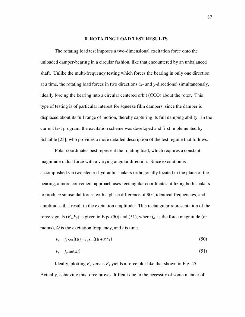
87
8. ROTATING LOAD TEST RESULTS
The rotating load test imposes a two-dimensional excitation force onto the
unloaded damper-bearing in a circular fashion, like that encountered by an unbalanced
shaft. Unlike the multi-frequency testing which forces the bearing in only one direction
at a time, the rotating load forces in two directions (x- and y-directions) simultaneously,
ideally forcing the bearing into a circular centered orbit (CCO) about the rotor. This
type of testing is of particular interest for squeeze film dampers, since the damper is
displaced about its full range of motion, thereby capturing its full damping ability. In the
current test program, the excitation scheme was developed and first implemented by
Schaible [23], who provides a more detailed description of the test regime that follows.
Polar coordinates best represent the rotating load, which requires a constant
magnitude radial force with a varying angular direction. Since excitation is
accomplished via two electro-hydraulic shakers orthogonally located in the plane of the
bearing, a more convenient approach uses rectangular coordinates utilizing both shakers
to produce sinusoidal forces with a phase difference of 90°, identical frequencies, and
amplitudes that result in the excitation amplitude. This rectangular representation of the
force signals (Fx,Fy) is given in Eqs. (50) and (51), where fo is the force magnitude (or
radius), Ω is the excitation frequency, and t is time.
( ) ( )2/sincos π+Ω=Ω= tftfF oox (50)
( )tfF oy Ω= sin (51)
Ideally, plotting Fy versus Fx yields a force plot like that shown in Fig. 45.
Actually, achieving this force proves difficult due to the necessity of some manner of
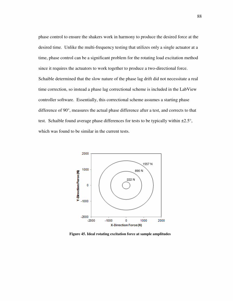
88
phase control to ensure the shakers work in harmony to produce the desired force at the
desired time. Unlike the multi-frequency testing that utilizes only a single actuator at a
time, phase control can be a significant problem for the rotating load excitation method
since it requires the actuators to work together to produce a two-directional force.
Schaible determined that the slow nature of the phase lag drift did not necessitate a real
time correction, so instead a phase lag correctional scheme is included in the LabView
controller software. Essentially, this correctional scheme assumes a starting phase
difference of 90°, measures the actual phase difference after a test, and corrects to that
test. Schaible found average phase differences for tests to be typically within ±2.5°,
which was found to be similar in the current tests.
Figure 45. Ideal rotating excitation force at sample amplitudes
890 N
1557 N
222 N
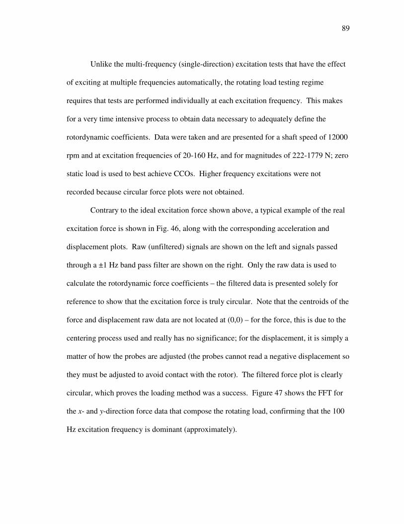
89
Unlike the multi-frequency (single-direction) excitation tests that have the effect
of exciting at multiple frequencies automatically, the rotating load testing regime
requires that tests are performed individually at each excitation frequency. This makes
for a very time intensive process to obtain data necessary to adequately define the
rotordynamic coefficients. Data were taken and are presented for a shaft speed of 12000
rpm and at excitation frequencies of 20-160 Hz, and for magnitudes of 222-1779 N; zero
static load is used to best achieve CCOs. Higher frequency excitations were not
recorded because circular force plots were not obtained.
Contrary to the ideal excitation force shown above, a typical example of the real
excitation force is shown in Fig. 46, along with the corresponding acceleration and
displacement plots. Raw (unfiltered) signals are shown on the left and signals passed
through a ±1 Hz band pass filter are shown on the right. Only the raw data is used to
calculate the rotordynamic force coefficients – the filtered data is presented solely for
reference to show that the excitation force is truly circular. Note that the centroids of the
force and displacement raw data are not located at (0,0) – for the force, this is due to the
centering process used and really has no significance; for the displacement, it is simply a
matter of how the probes are adjusted (the probes cannot read a negative displacement so
they must be adjusted to avoid contact with the rotor). The filtered force plot is clearly
circular, which proves the loading method was a success. Figure 47 shows the FFT for
the x- and y-direction force data that compose the rotating load, confirming that the 100
Hz excitation frequency is dominant (approximately).
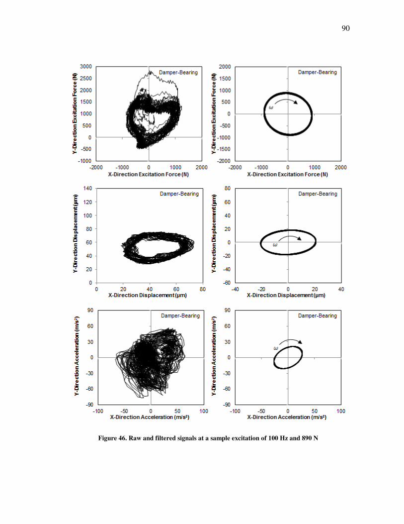
90
Figure 46. Raw and filtered signals at a sample excitation of 100 Hz and 890 N
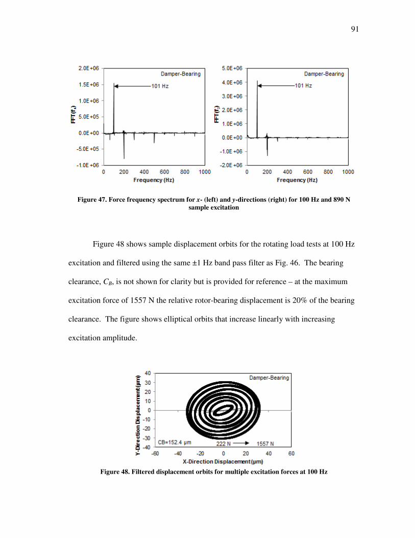
91
Figure 47. Force frequency spectrum for x- (left) and y-directions (right) for 100 Hz and 890 N
sample excitation
Figure 48 shows sample displacement orbits for the rotating load tests at 100 Hz
excitation and filtered using the same ±1 Hz band pass filter as Fig. 46. The bearing
clearance, CB, is not shown for clarity but is provided for reference – at the maximum
excitation force of 1557 N the relative rotor-bearing displacement is 20% of the bearing
clearance. The figure shows elliptical orbits that increase linearly with increasing
excitation amplitude.
Figure 48. Filtered displacement orbits for multiple excitation forces at 100 Hz
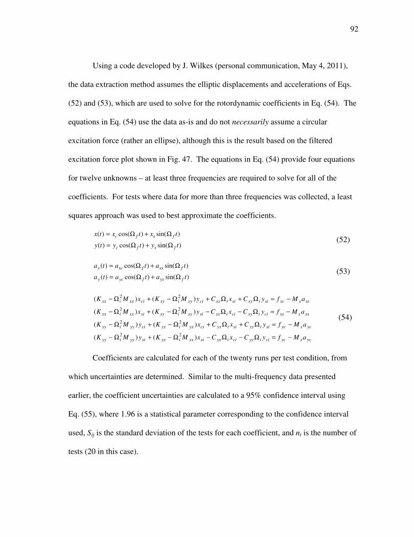
92
Using a code developed by J. Wilkes (personal communication, May 4, 2011),
the data extraction method assumes the elliptic displacements and accelerations of Eqs.
(52) and (53), which are used to solve for the rotordynamic coefficients in Eq. (54). The
equations in Eq. (54) use the data as-is and do not necessarily assume a circular
excitation force (rather an ellipse), although this is the result based on the filtered
excitation force plot shown in Fig. 47. The equations in Eq. (54) provide four equations
for twelve unknowns – at least three frequencies are required to solve for all of the
coefficients. For tests where data for more than three frequencies was collected, a least
squares approach was used to best approximate the coefficients.
)sin()cos()(
)sin()cos()(
tytyty
txtxtx
fsfc
fsfc
Ω+Ω=
Ω+Ω= (52)
)sin()cos()(
)sin()cos()(
tatata
tatata
fysfycy
fxsfxcx
Ω+Ω=
Ω+Ω= (53)
ycsycciiyyciiyxsiyxiyxsiyyiyy
ycsycsiiyysiiyxciyxiyxciyyiyy
xssxsciixyciixxsixyixysixxixx
xcsxcsiixysiixxcixyixycixxixx
aMfyCxCxMKyMK
aMfyCxCxMKyMK
aMfyCxCyMKxMK
aMfyCxCyMKxMK
−=Ω−Ω−Ω−+Ω−
−=Ω+Ω+Ω−+Ω−
−=Ω−Ω−Ω−+Ω−
−=Ω+Ω+Ω−+Ω−
)()(
)()(
)()(
)()(
22
22
22
22
(54)
Coefficients are calculated for each of the twenty runs per test condition, from
which uncertainties are determined. Similar to the multi-frequency data presented
earlier, the coefficient uncertainties are calculated to a 95% confidence interval using
Eq. (55), where 1.96 is a statistical parameter corresponding to the confidence interval
used, Sij is the standard deviation of the tests for each coefficient, and nt is the number of
tests (20 in this case).
93
t
ijij
t
ijij
t
ijij
n
SM
n
SC
n
SK
96.1
96.1
96.1
=∆
=∆
=∆
(55)
Figure 48 shows all of the rotordynamic coefficients measured using the rotating
load excitation and the corresponding multi-frequency excitation results measured
previously at 12000 rpm and zero static load. The direct stiffness results for the x- and
y-directions show low orthotropy for the rotating load. These stiffnesses decrease with
increasing excitation force and seem to converge to about 30 MN/m. At similar
excitation forces, the direct stiffness coefficients are about 30% less for the rotating load
method than for the multi-frequency tests. Cross-coupled stiffness coefficients range
from low to relatively high (compared with the direct terms) and there is no clear trend
with excitation force. Cross-coupled stiffness coefficients vary, but fall within the same
range as with the multi-frequency tests. At the highest excitation force, there is a hint
that the cross-coupled stiffnesses are converging toward zero, but additional testing at
higher excitation forces would be required to confirm this.
Direct damping coefficients do not follow an obvious trend relative to excitation
force. At similar excitation forces, the rotating load direct damping coefficients are
higher than those found with the rotating load tests – Cxx is about 40% higher and Cyy is
close to 65% higher. Cross-coupled damping coefficients are generally very high
relative to the direct terms (in excess of 50% at some excitation amplitudes). While these
coefficients initially diverge with increasing excitation force, it is unclear whether this
94
continues at higher excitation forces or if they have converged to some value. Cross-
coupled damping coefficients are three to four times larger for the rotating load than for
the multi-frequency results at similar excitation forces.
Direct added mass coefficients increase with excitation force and at similar
excitation forces are significantly larger than the multi-frequency results (two to six
times larger). This means that at higher frequencies the stiffness is lower for the rotating
load method. Cross-coupled added mass coefficients are erratic and do not correspond
well with the multi-frequency values at similar excitation amplitude.
As stated above, the direct stiffness and damping coefficients found with the
rotating load method are practically equivalent for each direction (low orthotropy) and
excitation amplitude. This is in contrast to the coefficients obtained using the multi-
frequency excitation which often differ somewhat in each direction. The coefficients of
determination for the rotating load stiffness, damping, and added mass coefficients is
excellent for all cases and ranges from R2 = 0.98 to 1.00. Three to six excitation
frequencies were used to calculate the rotordynamic coefficients (six at the lower
excitation amplitudes, decreasing to three at the higher amplitudes).
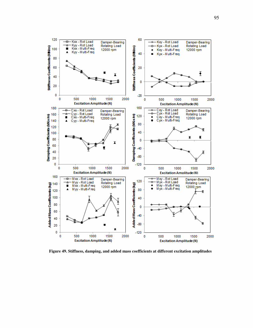
95
Figure 49. Stiffness, damping, and added mass coefficients at different excitation amplitudes
96
9. CONCLUSIONS
A four pad flexure-pivot-pad journal bearing in series with both a locked and
active ISFD was tested in load-between-pads (LBP) configuration to determine
performance characteristics of the bearing, and particularly, the effect of the ISFD on
these characteristics. Multiple test conditions (running speed and static load
combinations) and two excitation schemes are used to produce data, and compared to
predictions from appropriate models. For the FPJB (locked damper configuration),
rotordynamic coefficients from a similar bearing measured by another tester are
compared on a non-dimensional basis and increase the confidence in the results.
Static tests on both bearing configurations show low cross-coupling, as
evidenced by eccentricities that follow the loaded axis relatively well. Eccentricities
increase and attitude angles decrease with increasing load, as expected. The added
flexibility provided by the ISFD results in a lower stiffness for the damper-bearin (active
damper configuration), resulting in larger eccentricities on the order of 2-3 times those
measured for the FPJB alone. In fact, the addition of the damper allows eccentricities in
excess of the bearing clearance, CB. Attitude angles are not significantly different
between the FPJB and damper-bearing. For the FPJB, the commercial software under-
predicted the eccentricity but did an OK job of predicting the attitude angle.
Pad metal temperatures increase linearly with increasing load and running speed.
The pad metal temperatures are “flatter” for the damper-bearing than for the FPJB alone,
in that the temperatures change less along the circumference of the pads. Squeeze film
land metal temperatures recorded for the active damper tests increase linearly with load

97
and shaft speed, and the temperatures are nearly constant about the circumference of the
land. Power consumption for both bearing configurations remain approximately
constant with load, and increase almost linearly with increasing running speed. Both
bearing configurations consume the same amount of power, except at the lowest running
speed of 4000 rpm where the damper-bearing has a reduced power consumption of 1 to 2
kW. The power loss of the FPJB is under-predicted by about 1 to 2 kW, resulting in
relatively high errors at low shaft speeds; however, the accuracy increases to produce
good predictions at higher shaft speeds.
Although not realized during testing, a different order of testing the different
loads and shaft speeds might have provided slightly better results (i.e. eccentricities and
rotordynamic coefficients that follow the apparent trends better). Normally, both static
and dynamic data were collected at each test condition before changing test conditions;
however, after dynamic loading, the bearing did not always return to its precise location
about the rotor center, probably due to some residual loads on the shakers (as observed
at test rig shut down). Performing all static tests at a given shaft speed and then
performing all dynamic tests would likely have proven a better method, and at least
should have resulted in better eccentricity trends.
Both the FPJB and damper-bearing configurations were excited using the multi-
frequency excitation scheme. For both bearing configurations, the frequency
dependency of the real portions of the dynamic stiffnesses were found to be quadratic
and of the imaginary portions, linear. This means that the inclusion of added mass
coefficients creates frequency independent stiffness and damping coefficients.
98
Rotordynamic coefficients for the FPJB alone (locked damper configuration)
indicate an increase in stiffness and damping with increasing static load, and an increase
in stiffness and decrease in damping with increasing shaft speed. Cross-coupled
stiffnesses remain constant with increased load and diverge slightly with increased
running speed. Cross-coupled damping terms remain constant with both increased load
and running speed. Trends vary for the added mass coefficients. For the damper-
bearing, the measured rotordynamic coefficients change little with increased static
loading, although the direct stiffness tends to increase slightly, and the direct damping
tends to decrease slightly with increasing shaft speed.
A comparison of the rotordynamic coefficients for the FPJB and damper-bearing
results shows that the damping coefficients for the damper-bearing are often close to or
even less than the damping coefficients for the FPJB alone. Synchronous-response
analysis shows that, although the damping coefficients are on par with each other, the
reduced stiffness of the series damper-bearing produces greater effective damping. This
is clear in the analysis by a significant reduction in vibration amplitude of a simple rotor
at both the bearing and rotor mid-span locations.
For the FPJB, the intersections of the real direct stiffnesses are well predicted and
the intersections of the cross-coupled stiffnesses are predicted OK. Predictions
following [20] show a more linear change in stiffness with excitation frequency than
what the experimental results indicate. Since the synchronous damping value is used
from predictions as the damping coefficient, the software always yields a linear slope for
the imaginary portions of the dynamic stiffnesses; these curve fits are fair to good

99
depending on the test condition. Although not usually significant, the inclusion of the
fluid inertia option in the software [20] provides results overall closer to those obtained
experimentally.
Rotating load (single-frequency) tests performed on the damper-bearing force the
bearing into whirl about the rotor at prescribed excitation forces and frequencies, and are
used to calculate rotordynamic coefficients for comparison with the multi-frequency
excitation method at 12000 rpm and zero static load. Rotating load stiffness coefficients
are lower, and damping coefficients are higher, than those found with the multi-
frequency tests. The rotating load direct stiffness coefficients seem to head toward
convergence, but additional data would be required to confirm this. Added mass
coefficients increase with excitation force and are much higher than those found with the
multi-frequency tests.
Unlike the multi-frequency excitation method where the magnitudes of the direct
coefficients sometimes varied slightly between the x- and y-directions, the coefficients
are practically identical with the rotating load excitation, except for the added mass
coefficients which vary. The data suggests that the stability of a rotor-bearing system
might be significantly different than implied by the multi-frequency excitation method,
as evidenced by the difference in rotordynamic coefficients.
100
REFERENCES
[1] Grey, G.G., Hess, T.D. Jr., Leader, M.E., Whalen, J.K., 1996, “The Design and
Application of a Squeeze Film Damper Bearing to a Flexible Steam Turbine
Rotor,” Proceedings of the Twenty-Fifth Turbomachinery Symposium,
Turbomachinery Laboratory, Texas A&M University, pp. 49-57.
[2] Edney, S.L., 2003, “Pad Temperature in Tilting Pad Journal Bearings Influenced
By Operation High Speed and Light Load,” TP104, Dresser-Rand, Wellsville,
NY.
[3] Zeidan, F.Y., and Paquette, D.J., 1994, “Application of High Speed and High
Performance Fluid Film Bearings in Rotating Machinery,” Proceedings of the
Twenty-Third Turbomachinery Symposium, Turbomachinery Laboratory, Texas
A&M University, pp. 209-233.
[4] Szeri, A.Z., 1998, Fluid Film Lubrication Theory & Design, Cambridge
University Press, New York, NY, Chap. 4.
[5] Zeidan, F.Y., San Andrés, L., and Vance, J.M., 1996, “Design and Application of
Squeeze Film Dampers in Rotating Machinery,” Proceedings of the Twenty-Fifth
Turbomachinery Symposium, Turbomachinery Laboratory, Texas A&M
University, pp. 169-188.
[6] Al-Ghasem, A.M., 2004, “Measurement of Rotordynamic Coefficients for a High
Speed Flexure-Pivot Tilting-Pad Bearing (Load Between Pad) Configuration,”
M.S. Thesis, Texas A&M University, College Station, TX.
[7] Rodriguez Colmenares, L.E., 2004, “Experimental Frequency-Dependent
Rotordynamic Coefficients for a Load-On-Pad, High-Speed, Flexible-Pivot
Tilting-Pad Bearing,” M.S. Thesis, Texas A&M University, College Station, TX.
[8] San Andrés, L., and De Santiago, O., 2003, “Imbalance Response of a Rotor
Supported on Flexure Pivot Tilting Pad Journal Bearings in Series With Integral
Squeeze Film Dampers,” ASME J. Engr. for Gas Turb. Power, 125, pp. 1026-
1032.
[9] De Santiago, O., and San Andrés, L., 2007, “Field Methods for Identification of
Bearing Support Parameters – Part I: Identification From Transient Rotor
Dynamic Response due to Impacts,” ASME J. Engr. for Gas Turb. Power, 129,
pp. 205-212.
[10] De Santiago, O., and San Andrés, L., 2007, “Field Methods for Identification of
Bearing Support Parameters – Part II: Identification From Rotor Dynamic
101
Response due to Imbalances,” ASME J. Engr for Gas Turb. Power, 129, pp. 213-
219.
[11] De Santiago, O., and San Andrés, L., 1999, “Design of a Series Tilting Pad
Bearing and Squeeze Film Damper for NSF-TRC Rotordynamic Test Rig and
Analysis for Optimum Damping at Bearing Supports,” Turbomachinery Research
Consortium Annual Report, Texas A&M University, TRC-SFD-1-99, May.
[12] De Santiago, O., and San Andrés, L., 2000, “Measurements of the Imbalance
Response in a Rotor Supported on Tilting Pad Bearings and Integral Squeeze
Film Dampers,” Turbomachinery Research Consortium Annual Report, Texas
A&M University, TRC-SFD-1-00, May.
[13] De Santiago, O., and San Andrés, L., 2001, “Parameter Identification of Bearing
Supports from Imbalance Response and Impact Excitations,” Turbomachinery
Research Consortium Annual Report, Texas A&M University, TRC-RD-1-01,
May.
[14] Locke, S., and Faller, W., 2003, “Recycle Gas Compressor Designed for High
Unbalance Tolerance and Stability,” Proceedings of the Thirty-Second
Turbomachinery Symposium, Turbomachinery Laboratory, Texas A&M
University, pp. 137-144.
[15] Kaul, A., 1999, “Design and Development of a Test Setup for the Experimental
Determination of the Rotordynamic and Leakage Characteristics of Annular
Bushing Oil Seals,” M.S. Thesis, Texas A&M University, College Station, TX.
[16] Hibbeler, R.C., 2003, Mechanics of Materials, Pearson Education, Inc., Upper
Saddle River, NJ.
[17] Rouvas, C., and Childs, D.W., 1993, “A Parameter Identification Method for the
Rotordynamic Coefficients of a High Reynolds Number Hydrostatic Bearing,”
ASME J. Vib. and Acou., 115, pp. 264-270.
[18] Lund, J., 1967, “A Theoretical Analysis of Whirl Instability and Pneumatic
Hammer for a Rigid Rotor in Pressurized Gas Journal Bearings,” ASME J. Lubr.
Tech., 89, pp. 154-166.
[19] San Andrés, L., 1991, “Effect of Eccentricity on the Force Response of a Hybrid
Bearing, STLE Tribology Transactions, 34, pp. 537-544.
[20] San Andrés, L., 1995, “Bulk-Flow Analysis of Flexure and Tilting Pad Fluid
Film Bearings,” Turbomachinery Research Consortium Annual Report, Texas
A&M University, TRC-B&C-3-95, May.
102
[21] Pinkus, O., 1990, Thermal Aspects of Fluid Film Tribology, ASME Press, New
York, NY.
[22] Allaire, P.E., Barrett, L.E., and Gunter, E.J., 1978, “Optimum Bearing and
Support Damping for Unbalance Response and Stability of Rotating Machinery,”
ASME J. Engr. for Power, 100, pp. 89-94.
[23] Schaible, A., 2008 (Draft), “Static and Excitation-Amplitude-Dependent
Dynamic Parameters of a Tilting Pad Journal Bearing with Ball-in-Socket Pivots
in Load-On-Pad Configuration Measured Using Two Excitation Schemes,” M.S.
Thesis Draft, Texas A&M University, College Station, TX.

103
APPENDIX
NOTE: All off the dynamic stiffnesses and corresponding rotordynamic coefficients
presented in this section already have the baseline data subtracted from them.
Table 3. FPJB measured loci data
Running
Speed
(rpm)
Unit
Load
(kPa)
XDE
(µm)
XNDE
(µm)
YDE
(µm)
YNDE
(µm)
ex,ave
(µm)
ey,ave
(µm) εo,x (-) εo,y (-) εo (-) φ (deg)
4000 0 17.0 12.5 -3.2 -3.8 14.8 -3.5 0.10 -0.02 0.10 103.3
4000 172 12.3 9.6 27.6 25.3 11.0 26.4 0.07 0.17 0.19 22.5
4000 345 14.4 10.2 84.1 75.2 12.3 79.6 0.08 0.52 0.53 8.8
4000 517 8.1 4.5 100.7 90.2 6.3 95.5 0.04 0.63 0.63 3.8
4000 689 13.3 9.7 121.8 111.8 11.5 116.8 0.08 0.77 0.77 5.6
6000 0 26.0 17.2 0.1 -3.0 21.6 -1.5 0.14 -0.01 0.14 93.9
6000 172 26.4 18.5 34.9 31.5 22.5 33.2 0.15 0.22 0.26 34.1
6000 345 26.3 13.3 71.3 62.3 19.8 66.8 0.13 0.44 0.46 16.5
6000 517 10.8 1.0 93.1 83.7 5.9 88.4 0.04 0.58 0.58 3.8
6000 689 0.8 -5.3 92.4 86.6 -2.3 89.5 -0.01 0.59 0.59 -1.5
6000 862 -6.3 -6.3 104.0 97.7 -6.3 100.9 -0.04 0.66 0.66 -3.6
8000 0 43.7 31.2 -1.4 7.2 37.4 2.9 0.25 0.02 0.25 85.6
8000 172 48.9 34.6 30.6 37.7 41.7 34.1 0.27 0.22 0.35 50.7
8000 345 49.3 34.3 62.8 69.9 41.8 66.4 0.27 0.44 0.51 32.2
8000 517 22.3 14.3 63.7 70.5 18.3 67.1 0.12 0.44 0.46 15.3
8000 689 15.3 9.2 77.3 84.8 12.2 81.0 0.08 0.53 0.54 8.6
8000 862 22.2 20.8 104.9 110.2 21.5 107.6 0.14 0.71 0.72 11.3
10000 0 40.5 33.2 -1.8 8.4 36.8 3.3 0.24 0.02 0.24 84.9
10000 172 43.0 34.3 21.7 26.7 38.6 24.2 0.25 0.16 0.30 57.9
10000 345 47.8 37.1 52.3 59.8 42.4 56.1 0.28 0.37 0.46 37.1
10000 517 30.4 23.2 73.0 79.9 26.8 76.4 0.18 0.50 0.53 19.3
10000 689 17.1 12.6 70.2 79.4 14.9 74.8 0.10 0.49 0.50 11.2
10000 862 24.4 26.5 91.0 101.1 25.4 96.0 0.17 0.63 0.65 14.8
12000 0 45.6 31.3 -1.3 7.8 38.5 3.3 0.25 0.02 0.25 85.2
12000 172 51.8 43.4 17.7 27.0 47.6 22.4 0.31 0.15 0.35 64.8
12000 345 29.4 20.0 35.7 43.0 24.7 39.3 0.16 0.26 0.30 32.1
12000 517 19.3 14.8 43.0 56.2 17.0 49.6 0.11 0.33 0.34 18.9
12000 689 29.1 27.9 66.1 75.4 28.5 70.8 0.19 0.46 0.50 21.9
12000 862 36.1 38.6 95.9 108.7 37.4 102.3 0.25 0.67 0.71 20.1
EXPERIMENT
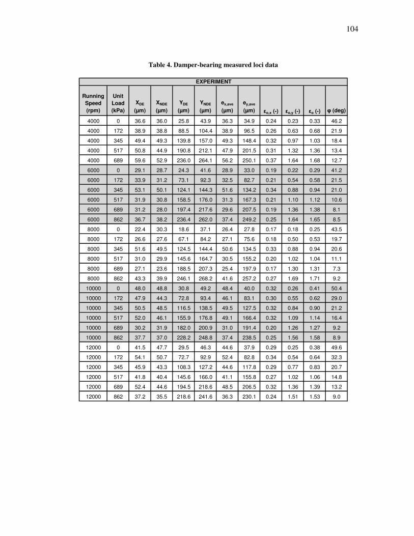
104
Table 4. Damper-bearing measured loci data
Running
Speed
(rpm)
Unit
Load
(kPa)
XDE
(µm)
XNDE
(µm)
YDE
(µm)
YNDE
(µm)
ex,ave
(µm)
ey,ave
(µm) εo,x (-) εo,y (-) εo (-) φ (deg)
4000 0 36.6 36.0 25.8 43.9 36.3 34.9 0.24 0.23 0.33 46.2
4000 172 38.9 38.8 88.5 104.4 38.9 96.5 0.26 0.63 0.68 21.9
4000 345 49.4 49.3 139.8 157.0 49.3 148.4 0.32 0.97 1.03 18.4
4000 517 50.8 44.9 190.8 212.1 47.9 201.5 0.31 1.32 1.36 13.4
4000 689 59.6 52.9 236.0 264.1 56.2 250.1 0.37 1.64 1.68 12.7
6000 0 29.1 28.7 24.3 41.6 28.9 33.0 0.19 0.22 0.29 41.2
6000 172 33.9 31.2 73.1 92.3 32.5 82.7 0.21 0.54 0.58 21.5
6000 345 53.1 50.1 124.1 144.3 51.6 134.2 0.34 0.88 0.94 21.0
6000 517 31.9 30.8 158.5 176.0 31.3 167.3 0.21 1.10 1.12 10.6
6000 689 31.2 28.0 197.4 217.6 29.6 207.5 0.19 1.36 1.38 8.1
6000 862 36.7 38.2 236.4 262.0 37.4 249.2 0.25 1.64 1.65 8.5
8000 0 22.4 30.3 18.6 37.1 26.4 27.8 0.17 0.18 0.25 43.5
8000 172 26.6 27.6 67.1 84.2 27.1 75.6 0.18 0.50 0.53 19.7
8000 345 51.6 49.5 124.5 144.4 50.6 134.5 0.33 0.88 0.94 20.6
8000 517 31.0 29.9 145.6 164.7 30.5 155.2 0.20 1.02 1.04 11.1
8000 689 27.1 23.6 188.5 207.3 25.4 197.9 0.17 1.30 1.31 7.3
8000 862 43.3 39.9 246.1 268.2 41.6 257.2 0.27 1.69 1.71 9.2
10000 0 48.0 48.8 30.8 49.2 48.4 40.0 0.32 0.26 0.41 50.4
10000 172 47.9 44.3 72.8 93.4 46.1 83.1 0.30 0.55 0.62 29.0
10000 345 50.5 48.5 116.5 138.5 49.5 127.5 0.32 0.84 0.90 21.2
10000 517 52.0 46.1 155.9 176.8 49.1 166.4 0.32 1.09 1.14 16.4
10000 689 30.2 31.9 182.0 200.9 31.0 191.4 0.20 1.26 1.27 9.2
10000 862 37.7 37.0 228.2 248.8 37.4 238.5 0.25 1.56 1.58 8.9
12000 0 41.5 47.7 29.5 46.3 44.6 37.9 0.29 0.25 0.38 49.6
12000 172 54.1 50.7 72.7 92.9 52.4 82.8 0.34 0.54 0.64 32.3
12000 345 45.9 43.3 108.3 127.2 44.6 117.8 0.29 0.77 0.83 20.7
12000 517 41.8 40.4 145.6 166.0 41.1 155.8 0.27 1.02 1.06 14.8
12000 689 52.4 44.6 194.5 218.6 48.5 206.5 0.32 1.36 1.39 13.2
12000 862 37.2 35.5 218.6 241.6 36.3 230.1 0.24 1.51 1.53 9.0
EXPERIMENT
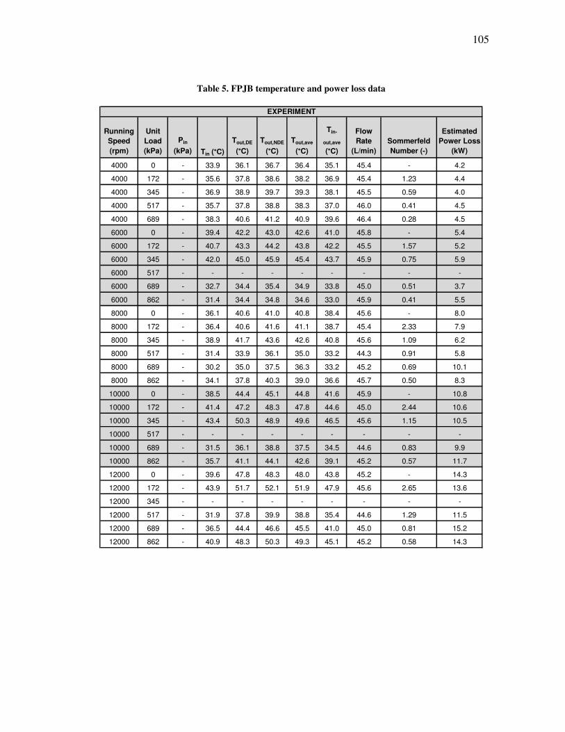
105
Table 5. FPJB temperature and power loss data
Running
Speed
(rpm)
Unit
Load
(kPa)
Pin
(kPa) Tin (°C)
Tout,DE
(°C)
Tout,NDE
(°C)
Tout,ave
(°C)
Tin-
out,ave
(°C)
Flow
Rate
(L/min)
Sommerfeld
Number (-)
Estimated
Power Loss
(kW)
4000 0 - 33.9 36.1 36.7 36.4 35.1 45.4 - 4.2
4000 172 - 35.6 37.8 38.6 38.2 36.9 45.4 1.23 4.4
4000 345 - 36.9 38.9 39.7 39.3 38.1 45.5 0.59 4.0
4000 517 - 35.7 37.8 38.8 38.3 37.0 46.0 0.41 4.5
4000 689 - 38.3 40.6 41.2 40.9 39.6 46.4 0.28 4.5
6000 0 - 39.4 42.2 43.0 42.6 41.0 45.8 - 5.4
6000 172 - 40.7 43.3 44.2 43.8 42.2 45.5 1.57 5.2
6000 345 - 42.0 45.0 45.9 45.4 43.7 45.9 0.75 5.9
6000 517 - - - - - - - - -
6000 689 - 32.7 34.4 35.4 34.9 33.8 45.0 0.51 3.7
6000 862 - 31.4 34.4 34.8 34.6 33.0 45.9 0.41 5.5
8000 0 - 36.1 40.6 41.0 40.8 38.4 45.6 - 8.0
8000 172 - 36.4 40.6 41.6 41.1 38.7 45.4 2.33 7.9
8000 345 - 38.9 41.7 43.6 42.6 40.8 45.6 1.09 6.2
8000 517 - 31.4 33.9 36.1 35.0 33.2 44.3 0.91 5.8
8000 689 - 30.2 35.0 37.5 36.3 33.2 45.2 0.69 10.1
8000 862 - 34.1 37.8 40.3 39.0 36.6 45.7 0.50 8.3
10000 0 - 38.5 44.4 45.1 44.8 41.6 45.9 - 10.8
10000 172 - 41.4 47.2 48.3 47.8 44.6 45.0 2.44 10.6
10000 345 - 43.4 50.3 48.9 49.6 46.5 45.6 1.15 10.5
10000 517 - - - - - - - - -
10000 689 - 31.5 36.1 38.8 37.5 34.5 44.6 0.83 9.9
10000 862 - 35.7 41.1 44.1 42.6 39.1 45.2 0.57 11.7
12000 0 - 39.6 47.8 48.3 48.0 43.8 45.2 - 14.3
12000 172 - 43.9 51.7 52.1 51.9 47.9 45.6 2.65 13.6
12000 345 - - - - - - - - -
12000 517 - 31.9 37.8 39.9 38.8 35.4 44.6 1.29 11.5
12000 689 - 36.5 44.4 46.6 45.5 41.0 45.0 0.81 15.2
12000 862 - 40.9 48.3 50.3 49.3 45.1 45.2 0.58 14.3
EXPERIMENT
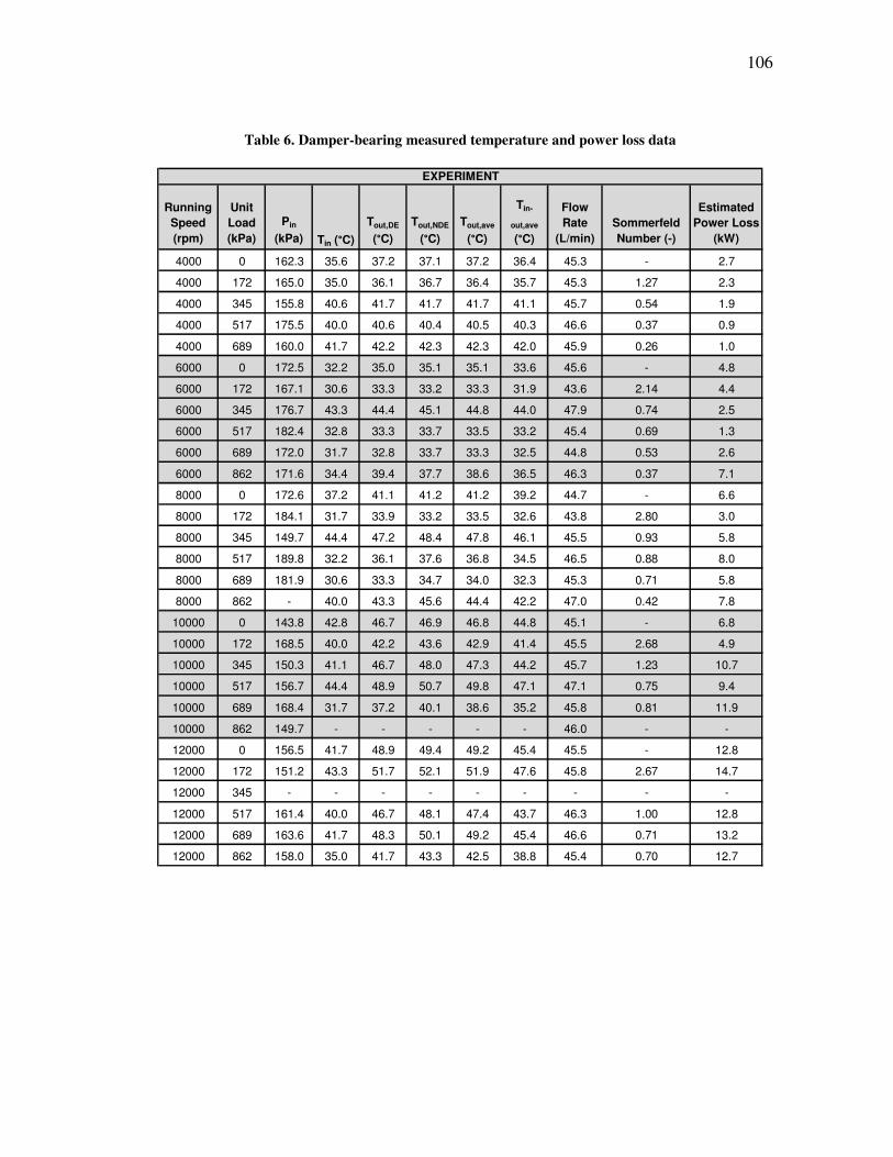
106
Table 6. Damper-bearing measured temperature and power loss data
Running
Speed
(rpm)
Unit
Load
(kPa)
Pin
(kPa) Tin (°C)
Tout,DE
(°C)
Tout,NDE
(°C)
Tout,ave
(°C)
Tin-
out,ave
(°C)
Flow
Rate
(L/min)
Sommerfeld
Number (-)
Estimated
Power Loss
(kW)
4000 0 162.3 35.6 37.2 37.1 37.2 36.4 45.3 - 2.7
4000 172 165.0 35.0 36.1 36.7 36.4 35.7 45.3 1.27 2.3
4000 345 155.8 40.6 41.7 41.7 41.7 41.1 45.7 0.54 1.9
4000 517 175.5 40.0 40.6 40.4 40.5 40.3 46.6 0.37 0.9
4000 689 160.0 41.7 42.2 42.3 42.3 42.0 45.9 0.26 1.0
6000 0 172.5 32.2 35.0 35.1 35.1 33.6 45.6 - 4.8
6000 172 167.1 30.6 33.3 33.2 33.3 31.9 43.6 2.14 4.4
6000 345 176.7 43.3 44.4 45.1 44.8 44.0 47.9 0.74 2.5
6000 517 182.4 32.8 33.3 33.7 33.5 33.2 45.4 0.69 1.3
6000 689 172.0 31.7 32.8 33.7 33.3 32.5 44.8 0.53 2.6
6000 862 171.6 34.4 39.4 37.7 38.6 36.5 46.3 0.37 7.1
8000 0 172.6 37.2 41.1 41.2 41.2 39.2 44.7 - 6.6
8000 172 184.1 31.7 33.9 33.2 33.5 32.6 43.8 2.80 3.0
8000 345 149.7 44.4 47.2 48.4 47.8 46.1 45.5 0.93 5.8
8000 517 189.8 32.2 36.1 37.6 36.8 34.5 46.5 0.88 8.0
8000 689 181.9 30.6 33.3 34.7 34.0 32.3 45.3 0.71 5.8
8000 862 - 40.0 43.3 45.6 44.4 42.2 47.0 0.42 7.8
10000 0 143.8 42.8 46.7 46.9 46.8 44.8 45.1 - 6.8
10000 172 168.5 40.0 42.2 43.6 42.9 41.4 45.5 2.68 4.9
10000 345 150.3 41.1 46.7 48.0 47.3 44.2 45.7 1.23 10.7
10000 517 156.7 44.4 48.9 50.7 49.8 47.1 47.1 0.75 9.4
10000 689 168.4 31.7 37.2 40.1 38.6 35.2 45.8 0.81 11.9
10000 862 149.7 - - - - - 46.0 - -
12000 0 156.5 41.7 48.9 49.4 49.2 45.4 45.5 - 12.8
12000 172 151.2 43.3 51.7 52.1 51.9 47.6 45.8 2.67 14.7
12000 345 - - - - - - - - -
12000 517 161.4 40.0 46.7 48.1 47.4 43.7 46.3 1.00 12.8
12000 689 163.6 41.7 48.3 50.1 49.2 45.4 46.6 0.71 13.2
12000 862 158.0 35.0 41.7 43.3 42.5 38.8 45.4 0.70 12.7
EXPERIMENT
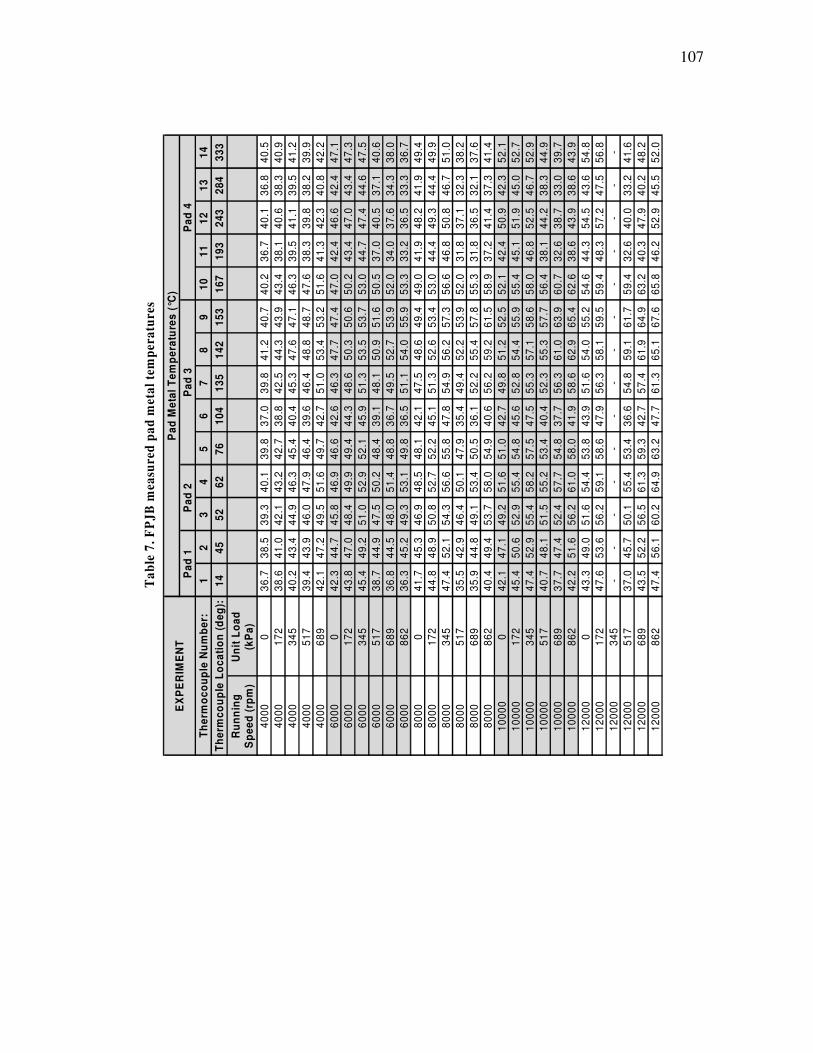
107
Table 7. FPJB measured pad metal temperatures
14
33
3
40
.5
40
.9
41
.2
39
.9
42
.2
47
.1
47
.3
47
.5
40
.6
38
.0
36
.7
49
.4
49
.9
51
.0
38
.2
37
.6
41
.4
52
.1
52
.7
52
.9
44
.9
39
.7
43
.9
54
.8
56
.8 -
41
.6
48
.2
52
.0
13
28
4
36
.8
38
.3
39
.5
38
.2
40
.8
42
.4
43
.4
44
.6
37
.1
34
.3
33
.3
41
.9
44
.4
46
.7
32
.3
32
.1
37
.3
42
.3
45
.0
46
.7
38
.3
33
.0
38
.6
43
.6
47
.5 -
33
.2
40
.2
45
.5
12
24
3
40
.1
40
.6
41
.1
39
.8
42
.3
46
.6
47
.0
47
.4
40
.5
37
.6
36
.5
48
.2
49
.3
50
.8
37
.1
36
.5
41
.4
50
.9
51
.9
52
.5
44
.2
38
.7
43
.9
54
.5
57
.2 -
40
.0
47
.9
52
.9
11
19
3
36
.7
38
.1
39
.5
38
.3
41
.3
42
.4
43
.4
44
.7
37
.0
34
.0
33
.2
41
.9
44
.4
46
.8
31
.8
31
.8
37
.2
42
.4
45
.1
46
.8
38
.1
32
.6
38
.6
44
.3
48
.3 -
32
.6
40
.3
46
.2
10
16
7
40
.2
43
.4
46
.3
47
.6
51
.6
47
.0
50
.2
53
.0
50
.5
52
.0
53
.3
49
.0
53
.0
56
.6
52
.0
55
.3
58
.9
52
.1
55
.4
58
.0
56
.4
60
.7
62
.6
54
.6
59
.4 -
59
.4
63
.2
65
.8
9
15
3
40
.7
43
.9
47
.1
48
.7
53
.2
47
.4
50
.6
53
.7
51
.6
53
.9
55
.9
49
.4
53
.4
57
.3
53
.9
57
.8
61
.5
52
.5
55
.9
58
.6
57
.7
63
.9
65
.4
55
.2
59
.5 -
61
.7
64
.9
67
.6
8
14
2
41
.2
44
.3
47
.6
48
.8
53
.4
47
.7
50
.3
53
.5
50
.9
52
.7
54
.0
48
.6
52
.6
56
.2
52
.2
55
.4
59
.2
51
.2
54
.4
57
.1
55
.3
61
.0
62
.9
54
.0
58
.1 -
59
.1
61
.9
65
.1
7
13
5
39
.8
42
.5
45
.3
46
.4
51
.0
46
.3
48
.6
51
.3
48
.1
49
.5
51
.1
47
.5
51
.3
54
.9
49
.4
52
.2
56
.2
49
.8
52
.8
55
.3
52
.3
56
.3
58
.6
51
.6
56
.3 -
54
.8
57
.4
61
.3
6
10
4
37
.0
38
.8
40
.4
39
.6
42
.7
42
.6
44
.3
45
.9
39
.1
36
.7
36
.5
42
.1
45
.1
47
.8
35
.4
36
.1
40
.6
42
.7
45
.6
47
.5
40
.4
37
.7
41
.9
43
.9
47
.9 -
36
.6
42
.7
47
.7
5 76
39
.8
42
.7
45
.4
46
.4
49
.7
46
.6
49
.4
52
.1
48
.4
48
.8
49
.8
48
.1
52
.2
55
.8
47
.9
50
.5
54
.9
51
.0
54
.8
57
.5
53
.4
54
.8
58
.0
53
.8
58
.6 -
53
.4
59
.3
63
.2
4 62
40
.1
43
.2
46
.3
47
.9
51
.6
46
.9
49
.9
52
.9
50
.2
51
.4
53
.1
48
.5
52
.7
56
.6
50
.1
53
.4
58
.0
51
.6
55
.4
58
.2
55
.2
57
.7
61
.0
54
.4
59
.1 -
55
.4
61
.3
64
.9
3 52
39
.3
42
.1
44
.9
46
.0
49
.5
45
.8
48
.4
51
.0
47
.5
48
.0
49
.3
46
.9
50
.8
54
.3
46
.4
49
.1
53
.7
49
.2
52
.9
55
.4
51
.5
52
.4
56
.2
51
.6
56
.2 -
50
.1
56
.5
60
.2
2 45
38
.5
41
.0
43
.4
43
.9
47
.2
44
.7
47
.0
49
.2
44
.9
44
.5
45
.2
45
.3
48
.9
52
.1
42
.9
44
.8
49
.4
47
.1
50
.6
52
.9
48
.1
47
.4
51
.6
49
.0
53
.6 -
45
.7
52
.2
56
.1
1 14
36
.7
38
.6
40
.2
39
.4
42
.1
42
.3
43
.8
45
.4
38
.7
36
.8
36
.3
41
.7
44
.8
47
.4
35
.5
35
.9
40
.4
42
.1
45
.4
47
.4
40
.7
37
.7
42
.2
43
.3
47
.6 -
37
.0
43
.5
47
.4
Un
it L
oa
d
(kP
a)
0
17
2
34
5
51
7
68
9
0
17
2
34
5
51
7
68
9
86
2
0
17
2
34
5
51
7
68
9
86
2
0
17
2
34
5
51
7
68
9
86
2
0
17
2
34
5
51
7
68
9
86
2
Ru
nn
ing
S
pe
ed
(rp
m)
40
00
40
00
40
00
40
00
40
00
60
00
60
00
60
00
60
00
60
00
60
00
80
00
80
00
80
00
80
00
80
00
80
00
10
00
0
10
00
0
10
00
0
10
00
0
10
00
0
10
00
0
12
00
0
12
00
0
12
00
0
12
00
0
12
00
0
12
00
0
Th
erm
oc
ou
ple
Nu
mb
er:
Th
erm
co
up
le L
oc
ati
on
(d
eg
):
EX
PE
RIM
EN
TP
ad
1P
ad
4P
ad
3P
ad
2
Pa
d M
eta
l T
em
pe
ratu
res
(°C
)
Ta
ble
7.
FP
JB
mea
sure
d p
ad
met
al
tem
per
atu
res
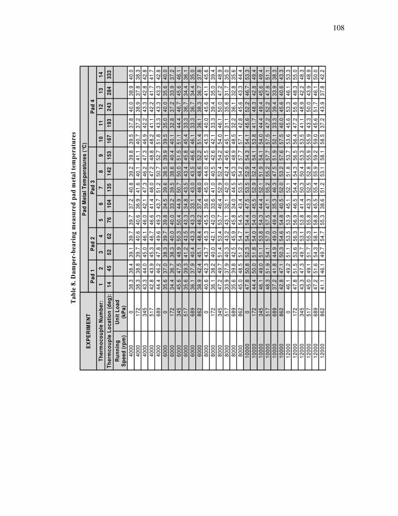
108
Table 8. Damper-bearing measured pad metal temperatures
14
33
3
40
.0
38
.3
42
.8
41
.7
42
.8
40
.0
37
.2
46
.1
36
.1
35
.0
37
.8
45
.6
39
.4
48
.9
35
.0
35
.6
44
.4
53
.3
49
.4
49
.4
51
.1
38
.3
43
.3
53
.3
55
.0
48
.3
48
.9
50
.0
42
.2
13
28
4
38
.9
37
.8
42
.8
41
.7
43
.3
35
.6
33
.9
45
.6
34
.4
34
.4
36
.7
41
.1
35
.0
47
.2
31
.7
32
.8
43
.3
46
.7
42
.8
45
.6
47
.8
33
.9
40
.6
46
.1
48
.3
42
.2
43
.9
46
.1
37
.8
12
24
3
40
.0
38
.9
43
.3
42
.2
43
.3
40
.0
37
.2
46
.7
36
.7
36
.7
38
.3
45
.6
39
.4
50
.0
35
.6
36
.1
45
.6
52
.2
48
.3
49
.4
52
.2
39
.4
45
.6
53
.3
55
.6
48
.9
50
.0
51
.7
43
.9
11
19
3
37
.8
37
.2
42
.2
41
.1
43
.3
35
.0
32
.8
44
.4
33
.3
33
.3
36
.1
40
.0
33
.3
46
.1
31
.1
32
.2
42
.8
45
.6
41
.7
44
.4
47
.2
33
.3
40
.0
45
.6
47
.2
41
.1
43
.3
45
.6
37
.2
10
16
7
39
.5
40
.7
46
.9
48
.2
51
.8
39
.5
40
.1
51
.1
45
.4
46
.1
51
.4
45
.3
42
.1
54
.0
45
.1
48
.5
57
.1
54
.1
53
.8
54
.0
57
.5
52
.1
57
.5
53
.6
56
.4
53
.5
55
.9
59
.0
58
.5
9
15
3
39
.8
41
.1
47
.3
48
.8
52
.7
39
.9
40
.4
51
.5
45
.8
46
.6
52
.2
45
.5
42
.6
54
.2
45
.6
48
.9
57
.7
54
.3
54
.1
54
.1
57
.7
51
.9
57
.6
53
.7
56
.5
53
.3
55
.9
59
.2
58
.1
8
14
2
39
.2
40
.1
46
.2
47
.2
50
.7
38
.5
38
.6
50
.0
43
.4
43
.5
48
.6
44
.0
40
.5
52
.4
42
.4
45
.3
54
.2
52
.9
52
.4
51
.9
55
.2
47
.5
53
.2
51
.8
54
.3
50
.4
52
.8
55
.9
53
.1
7
13
5
40
.8
41
.6
47
.3
48
.0
51
.2
39
.6
39
.5
50
.7
43
.5
43
.0
48
.0
45
.0
41
.0
52
.9
42
.0
44
.5
53
.5
53
.5
52
.9
52
.1
55
.2
46
.3
52
.0
52
.1
54
.4
50
.3
52
.5
55
.4
51
.2
6
10
4
37
.2
36
.9
42
.1
41
.4
43
.7
34
.5
33
.2
44
.9
34
.8
33
.1
37
.4
39
.6
33
.6
46
.4
32
.1
34
.0
43
.4
47
.5
45
.5
44
.4
47
.1
35
.3
40
.5
45
.1
46
.5
41
.4
43
.3
45
.5
38
.6
5 76
39
.7
40
.6
46
.0
46
.6
49
.3
39
.8
40
.0
50
.4
43
.3
43
.3
48
.2
45
.5
42
.0
53
.7
43
.1
45
.8
54
.5
54
.4
54
.0
54
.3
57
.5
49
.4
54
.8
53
.9
56
.9
53
.8
55
.8
58
.8
55
.3
4 62
39
.7
40
.6
46
.1
46
.7
49
.6
39
.7
40
.0
50
.3
43
.5
43
.3
48
.4
45
.3
42
.1
53
.4
43
.2
45
.9
54
.7
54
.1
54
.0
53
.8
57
.0
49
.0
54
.6
53
.5
56
.3
53
.1
55
.3
58
.1
54
.7
3 52
39
.1
39
.7
45
.0
45
.3
47
.8
38
.3
38
.3
48
.9
41
.2
40
.4
45
.1
43
.7
40
.0
51
.4
40
.3
42
.5
51
.2
52
.3
51
.8
51
.1
54
.1
44
.9
50
.3
51
.1
53
.6
49
.7
51
.7
54
.3
49
.7
2 45
38
.4
38
.8
44
.0
43
.9
46
.2
37
.0
36
.7
47
.5
39
.3
37
.9
42
.4
42
.3
38
.2
49
.7
37
.9
39
.8
48
.5
50
.8
50
.0
49
.0
51
.9
41
.8
47
.1
49
.2
51
.5
47
.3
49
.1
51
.6
46
.1
1 14
38
.3
38
.3
43
.3
42
.8
44
.4
35
.6
34
.4
45
.6
35
.6
36
.1
38
.9
40
.6
36
.1
47
.2
33
.9
35
.6
45
.0
47
.8
44
.4
46
.1
48
.3
37
.2
42
.8
46
.1
47
.8
43
.3
45
.0
47
.2
41
.1
Un
it L
oa
d
(kP
a)
0
17
2
34
5
51
7
68
9
0
17
2
34
5
51
7
68
9
86
2
0
17
2
34
5
51
7
68
9
86
2
0
17
2
34
5
51
7
68
9
86
2
0
17
2
34
5
51
7
68
9
86
2
Ru
nn
ing
S
pe
ed
(rp
m)
40
00
40
00
40
00
40
00
40
00
60
00
60
00
60
00
60
00
60
00
60
00
80
00
80
00
80
00
80
00
80
00
80
00
10
00
0
10
00
0
10
00
0
10
00
0
10
00
0
10
00
0
12
00
0
12
00
0
12
00
0
12
00
0
12
00
0
12
00
0
Pa
d M
eta
l T
em
pe
ratu
res
(°C
)
Pa
d 4
Pa
d 3
Pa
d 2
Pa
d 1
EX
PE
RIM
EN
T
Ta
ble
8.
Da
mp
er-b
eari
ng
mea
sure
d p
ad
met
al
tem
per
atu
res
Th
erm
oc
ou
ple
Nu
mb
er:
Th
erm
co
up
le L
oc
ati
on
(d
eg
):
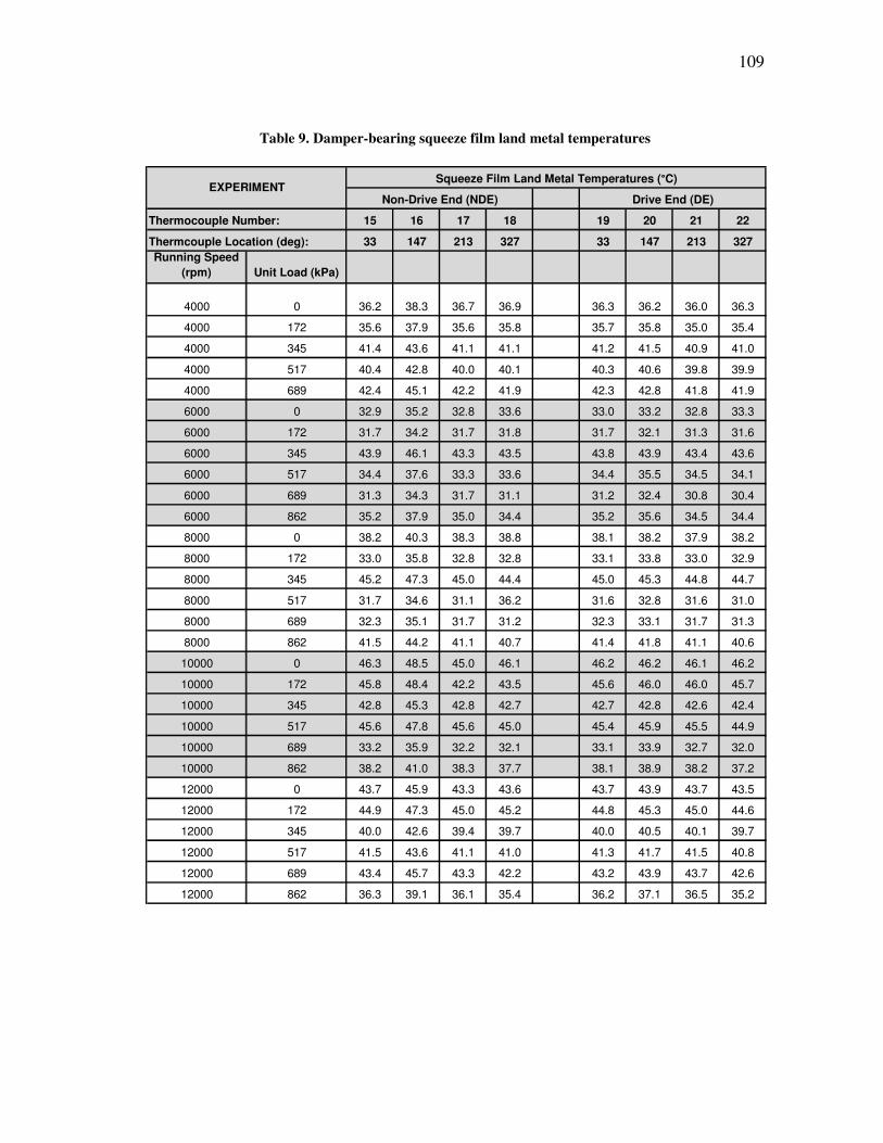
109
Table 9. Damper-bearing squeeze film land metal temperatures
Thermocouple Number: 15 16 17 18 19 20 21 22
Thermcouple Location (deg): 33 147 213 327 33 147 213 327
Running Speed
(rpm) Unit Load (kPa)
4000 0 36.2 38.3 36.7 36.9 36.3 36.2 36.0 36.3
4000 172 35.6 37.9 35.6 35.8 35.7 35.8 35.0 35.4
4000 345 41.4 43.6 41.1 41.1 41.2 41.5 40.9 41.0
4000 517 40.4 42.8 40.0 40.1 40.3 40.6 39.8 39.9
4000 689 42.4 45.1 42.2 41.9 42.3 42.8 41.8 41.9
6000 0 32.9 35.2 32.8 33.6 33.0 33.2 32.8 33.3
6000 172 31.7 34.2 31.7 31.8 31.7 32.1 31.3 31.6
6000 345 43.9 46.1 43.3 43.5 43.8 43.9 43.4 43.6
6000 517 34.4 37.6 33.3 33.6 34.4 35.5 34.5 34.1
6000 689 31.3 34.3 31.7 31.1 31.2 32.4 30.8 30.4
6000 862 35.2 37.9 35.0 34.4 35.2 35.6 34.5 34.4
8000 0 38.2 40.3 38.3 38.8 38.1 38.2 37.9 38.2
8000 172 33.0 35.8 32.8 32.8 33.1 33.8 33.0 32.9
8000 345 45.2 47.3 45.0 44.4 45.0 45.3 44.8 44.7
8000 517 31.7 34.6 31.1 36.2 31.6 32.8 31.6 31.0
8000 689 32.3 35.1 31.7 31.2 32.3 33.1 31.7 31.3
8000 862 41.5 44.2 41.1 40.7 41.4 41.8 41.1 40.6
10000 0 46.3 48.5 45.0 46.1 46.2 46.2 46.1 46.2
10000 172 45.8 48.4 42.2 43.5 45.6 46.0 46.0 45.7
10000 345 42.8 45.3 42.8 42.7 42.7 42.8 42.6 42.4
10000 517 45.6 47.8 45.6 45.0 45.4 45.9 45.5 44.9
10000 689 33.2 35.9 32.2 32.1 33.1 33.9 32.7 32.0
10000 862 38.2 41.0 38.3 37.7 38.1 38.9 38.2 37.2
12000 0 43.7 45.9 43.3 43.6 43.7 43.9 43.7 43.5
12000 172 44.9 47.3 45.0 45.2 44.8 45.3 45.0 44.6
12000 345 40.0 42.6 39.4 39.7 40.0 40.5 40.1 39.7
12000 517 41.5 43.6 41.1 41.0 41.3 41.7 41.5 40.8
12000 689 43.4 45.7 43.3 42.2 43.2 43.9 43.7 42.6
12000 862 36.3 39.1 36.1 35.4 36.2 37.1 36.5 35.2
Drive End (DE)Non-Drive End (NDE)
Squeeze Film Land Metal Temperatures (°C)EXPERIMENT
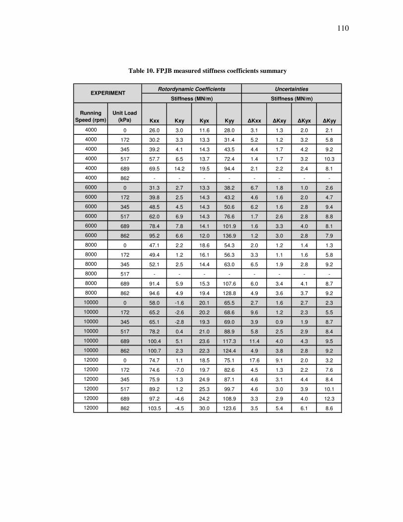
110
Table 10. FPJB measured stiffness coefficients summary
Running
Speed (rpm)
Unit Load
(kPa) Kxx Kxy Kyx Kyy ∆Kxx ∆Kxy ∆Kyx ∆Kyy
4000 0 26.0 3.0 11.6 28.0 3.1 1.3 2.0 2.1
4000 172 30.2 3.3 13.3 31.4 5.2 1.2 3.2 5.8
4000 345 39.2 4.1 14.3 43.5 4.4 1.7 4.2 9.2
4000 517 57.7 6.5 13.7 72.4 1.4 1.7 3.2 10.3
4000 689 69.5 14.2 19.5 94.4 2.1 2.2 2.4 8.1
4000 862 - - - - - - - -
6000 0 31.3 2.7 13.3 38.2 6.7 1.8 1.0 2.6
6000 172 39.8 2.5 14.3 43.2 4.6 1.6 2.0 4.7
6000 345 48.5 4.5 14.3 50.6 6.2 1.6 2.8 9.4
6000 517 62.0 6.9 14.3 76.6 1.7 2.6 2.8 8.8
6000 689 78.4 7.8 14.1 101.9 1.6 3.3 4.0 8.1
6000 862 95.2 6.6 12.0 136.9 1.2 3.0 2.8 7.9
8000 0 47.1 2.2 18.6 54.3 2.0 1.2 1.4 1.3
8000 172 49.4 1.2 16.1 56.3 3.3 1.1 1.6 5.8
8000 345 52.1 2.5 14.4 63.0 6.5 1.9 2.8 9.2
8000 517 - - - - - - - -
8000 689 91.4 5.9 15.3 107.6 6.0 3.4 4.1 8.7
8000 862 94.6 4.9 19.4 128.8 4.9 3.6 3.7 9.2
10000 0 58.0 -1.6 20.1 65.5 2.7 1.6 2.7 2.3
10000 172 65.2 -2.6 20.2 68.6 9.6 1.2 2.3 5.5
10000 345 65.1 -2.8 19.3 69.0 3.9 0.9 1.9 8.7
10000 517 78.2 0.4 21.0 88.9 5.8 2.5 2.9 8.4
10000 689 100.4 5.1 23.6 117.3 11.4 4.0 4.3 9.5
10000 862 100.7 2.3 22.3 124.4 4.9 3.8 2.8 9.2
12000 0 74.7 1.1 18.5 75.1 17.6 9.1 2.0 3.2
12000 172 74.6 -7.0 19.7 82.6 4.5 1.3 2.2 7.6
12000 345 75.9 1.3 24.9 87.1 4.6 3.1 4.4 8.4
12000 517 89.2 1.2 25.3 99.7 4.6 3.0 3.9 10.1
12000 689 97.2 -4.6 24.2 108.9 3.3 2.9 4.0 12.3
12000 862 103.5 -4.5 30.0 123.6 3.5 5.4 6.1 8.6
Rotordynamic Coefficients UncertaintiesEXPERIMENT
Stiffness (MN/m) Stiffness (MN/m)
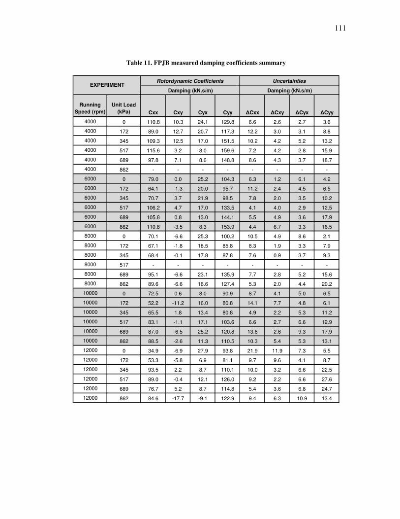
111
Table 11. FPJB measured damping coefficients summary
Running
Speed (rpm)
Unit Load
(kPa) Cxx Cxy Cyx Cyy ∆Cxx ∆Cxy ∆Cyx ∆Cyy
4000 0 110.8 10.3 24.1 129.8 6.6 2.6 2.7 3.6
4000 172 89.0 12.7 20.7 117.3 12.2 3.0 3.1 8.8
4000 345 109.3 12.5 17.0 151.5 10.2 4.2 5.2 13.2
4000 517 115.6 3.2 8.0 159.6 7.2 4.2 2.8 15.9
4000 689 97.8 7.1 8.6 148.8 8.6 4.3 3.7 18.7
4000 862 - - - - - - - -
6000 0 79.0 0.0 25.2 104.3 6.3 1.2 6.1 4.2
6000 172 64.1 -1.3 20.0 95.7 11.2 2.4 4.5 6.5
6000 345 70.7 3.7 21.9 98.5 7.8 2.0 3.5 10.2
6000 517 106.2 4.7 17.0 133.5 4.1 4.0 2.9 12.5
6000 689 105.8 0.8 13.0 144.1 5.5 4.9 3.6 17.9
6000 862 110.8 -3.5 8.3 153.9 4.4 6.7 3.3 16.5
8000 0 70.1 -6.6 25.3 100.2 10.5 4.9 8.6 2.1
8000 172 67.1 -1.8 18.5 85.8 8.3 1.9 3.3 7.9
8000 345 68.4 -0.1 17.8 87.8 7.6 0.9 3.7 9.3
8000 517 - - - - - - - -
8000 689 95.1 -6.6 23.1 135.9 7.7 2.8 5.2 15.6
8000 862 89.6 -6.6 16.6 127.4 5.3 2.0 4.4 20.2
10000 0 72.5 0.6 8.0 90.9 8.7 4.1 5.0 6.5
10000 172 52.2 -11.2 16.0 80.8 14.1 7.7 4.8 6.1
10000 345 65.5 1.8 13.4 80.8 4.9 2.2 5.3 11.2
10000 517 83.1 -1.1 17.1 103.6 6.6 2.7 6.6 12.9
10000 689 87.0 -6.5 25.2 120.8 13.6 2.6 9.3 17.9
10000 862 88.5 -2.6 11.3 110.5 10.3 5.4 5.3 13.1
12000 0 34.9 -6.9 27.9 93.8 21.9 11.9 7.3 5.5
12000 172 53.3 -5.8 6.9 81.1 9.7 9.6 4.1 8.7
12000 345 93.5 2.2 8.7 110.1 10.0 3.2 6.6 22.5
12000 517 89.0 -0.4 12.1 126.0 9.2 2.2 6.6 27.6
12000 689 76.7 5.2 8.7 114.8 5.4 3.6 6.8 24.7
12000 862 84.6 -17.7 -9.1 122.9 9.4 6.3 10.9 13.4
Rotordynamic CoefficientsEXPERIMENT
Uncertainties
Damping (kN.s/m) Damping (kN.s/m)
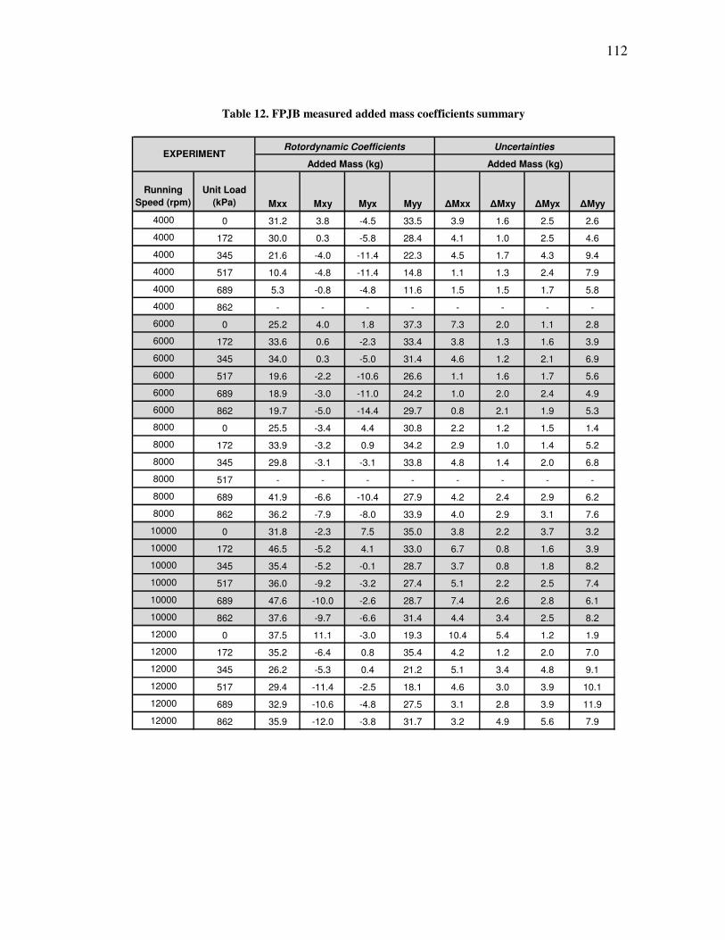
112
Table 12. FPJB measured added mass coefficients summary
Running
Speed (rpm)
Unit Load
(kPa) Mxx Mxy Myx Myy ∆Mxx ∆Mxy ∆Myx ∆Myy
4000 0 31.2 3.8 -4.5 33.5 3.9 1.6 2.5 2.6
4000 172 30.0 0.3 -5.8 28.4 4.1 1.0 2.5 4.6
4000 345 21.6 -4.0 -11.4 22.3 4.5 1.7 4.3 9.4
4000 517 10.4 -4.8 -11.4 14.8 1.1 1.3 2.4 7.9
4000 689 5.3 -0.8 -4.8 11.6 1.5 1.5 1.7 5.8
4000 862 - - - - - - - -
6000 0 25.2 4.0 1.8 37.3 7.3 2.0 1.1 2.8
6000 172 33.6 0.6 -2.3 33.4 3.8 1.3 1.6 3.9
6000 345 34.0 0.3 -5.0 31.4 4.6 1.2 2.1 6.9
6000 517 19.6 -2.2 -10.6 26.6 1.1 1.6 1.7 5.6
6000 689 18.9 -3.0 -11.0 24.2 1.0 2.0 2.4 4.9
6000 862 19.7 -5.0 -14.4 29.7 0.8 2.1 1.9 5.3
8000 0 25.5 -3.4 4.4 30.8 2.2 1.2 1.5 1.4
8000 172 33.9 -3.2 0.9 34.2 2.9 1.0 1.4 5.2
8000 345 29.8 -3.1 -3.1 33.8 4.8 1.4 2.0 6.8
8000 517 - - - - - - - -
8000 689 41.9 -6.6 -10.4 27.9 4.2 2.4 2.9 6.2
8000 862 36.2 -7.9 -8.0 33.9 4.0 2.9 3.1 7.6
10000 0 31.8 -2.3 7.5 35.0 3.8 2.2 3.7 3.2
10000 172 46.5 -5.2 4.1 33.0 6.7 0.8 1.6 3.9
10000 345 35.4 -5.2 -0.1 28.7 3.7 0.8 1.8 8.2
10000 517 36.0 -9.2 -3.2 27.4 5.1 2.2 2.5 7.4
10000 689 47.6 -10.0 -2.6 28.7 7.4 2.6 2.8 6.1
10000 862 37.6 -9.7 -6.6 31.4 4.4 3.4 2.5 8.2
12000 0 37.5 11.1 -3.0 19.3 10.4 5.4 1.2 1.9
12000 172 35.2 -6.4 0.8 35.4 4.2 1.2 2.0 7.0
12000 345 26.2 -5.3 0.4 21.2 5.1 3.4 4.8 9.1
12000 517 29.4 -11.4 -2.5 18.1 4.6 3.0 3.9 10.1
12000 689 32.9 -10.6 -4.8 27.5 3.1 2.8 3.9 11.9
12000 862 35.9 -12.0 -3.8 31.7 3.2 4.9 5.6 7.9
Rotordynamic CoefficientsEXPERIMENT
Added Mass (kg)
Uncertainties
Added Mass (kg)
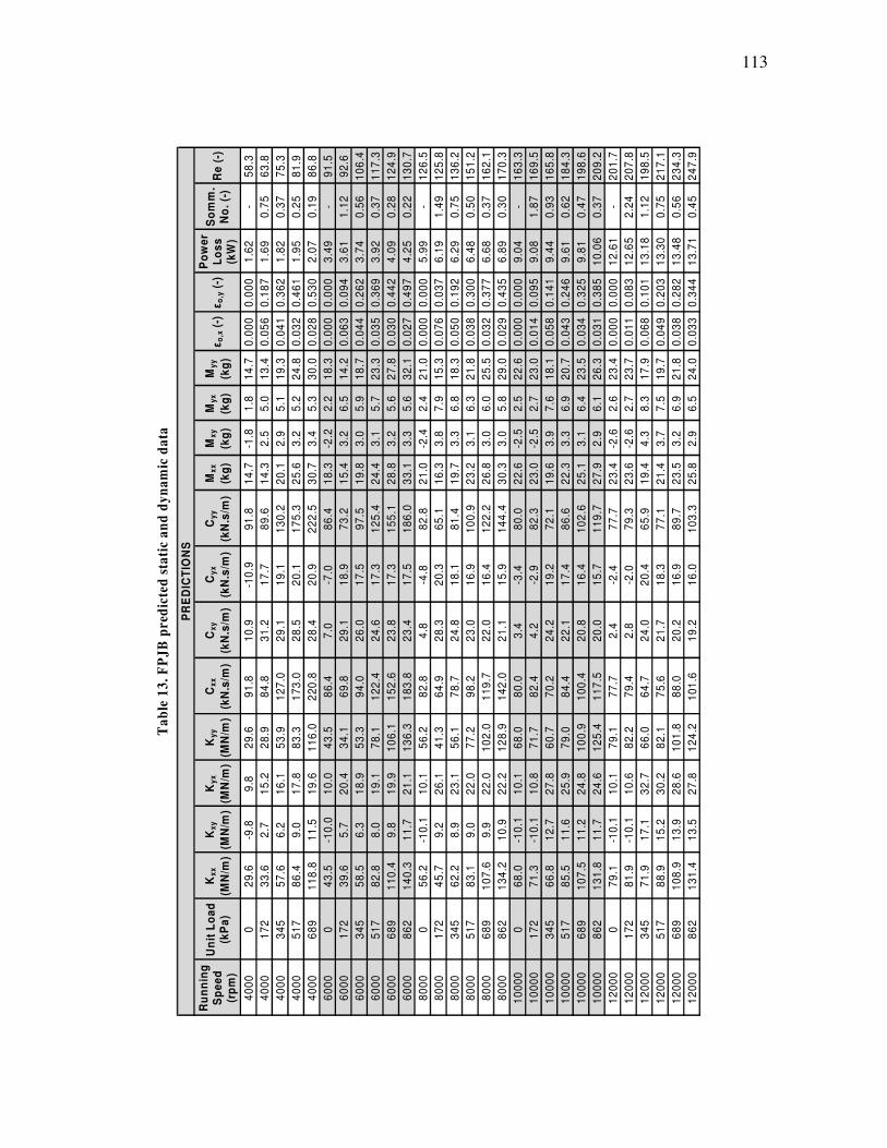
113
Table 13. FPJB predicted static and dynamic data
Re
(-)
58
.3
63
.8
75
.3
81
.9
86
.8
91
.5
92
.6
10
6.4
11
7.3
12
4.9
13
0.7
12
6.5
12
5.8
13
6.2
15
1.2
16
2.1
17
0.3
16
3.3
16
9.5
16
5.8
18
4.3
19
8.6
20
9.2
20
1.7
20
7.8
19
8.5
21
7.1
23
4.3
24
7.9
So
mm
. N
o.
(-)
-
0.7
5
0.3
7
0.2
5
0.1
9
-
1.1
2
0.5
6
0.3
7
0.2
8
0.2
2
-
1.4
9
0.7
5
0.5
0
0.3
7
0.3
0
-
1.8
7
0.9
3
0.6
2
0.4
7
0.3
7
-
2.2
4
1.1
2
0.7
5
0.5
6
0.4
5
Po
we
r L
os
s
(kW
)
1.6
2
1.6
9
1.8
2
1.9
5
2.0
7
3.4
9
3.6
1
3.7
4
3.9
2
4.0
9
4.2
5
5.9
9
6.1
9
6.2
9
6.4
8
6.6
8
6.8
9
9.0
4
9.0
8
9.4
4
9.6
1
9.8
1
10
.06
12
.61
12
.65
13
.18
13
.30
13
.48
13
.71
εo
,y (
-)
0.0
00
0.1
87
0.3
62
0.4
61
0.5
30
0.0
00
0.0
94
0.2
62
0.3
69
0.4
42
0.4
97
0.0
00
0.0
37
0.1
92
0.3
00
0.3
77
0.4
35
0.0
00
0.0
95
0.1
41
0.2
46
0.3
25
0.3
85
0.0
00
0.0
83
0.1
01
0.2
03
0.2
82
0.3
44
εo
,x (
-)
0.0
00
0.0
56
0.0
41
0.0
32
0.0
28
0.0
00
0.0
63
0.0
44
0.0
35
0.0
30
0.0
27
0.0
00
0.0
76
0.0
50
0.0
38
0.0
32
0.0
29
0.0
00
0.0
14
0.0
58
0.0
43
0.0
34
0.0
31
0.0
00
0.0
11
0.0
68
0.0
49
0.0
38
0.0
33
My
y
(kg
)
14
.7
13
.4
19
.3
24
.8
30
.0
18
.3
14
.2
18
.7
23
.3
27
.8
32
.1
21
.0
15
.3
18
.3
21
.8
25
.5
29
.0
22
.6
23
.0
18
.1
20
.7
23
.5
26
.3
23
.4
23
.7
17
.9
19
.7
21
.8
24
.0
My
x
(kg
)
1.8
5.0
5.1
5.2
5.3
2.2
6.5
5.9
5.7
5.6
5.6
2.4
7.9
6.8
6.3
6.0
5.8
2.5
2.7
7.6
6.9
6.4
6.1
2.6
2.7
8.3
7.5
6.9
6.5
Mx
y
(kg
)
-1.8
2.5
2.9
3.2
3.4
-2.2
3.2
3.0
3.1
3.2
3.3
-2.4
3.8
3.3
3.1
3.0
3.0
-2.5
-2.5
3.9
3.3
3.1
2.9
-2.6
-2.6
4.3
3.7
3.2
2.9
Mx
x
(kg
)
14
.7
14
.3
20
.1
25
.6
30
.7
18
.3
15
.4
19
.8
24
.4
28
.8
33
.1
21
.0
16
.3
19
.7
23
.2
26
.8
30
.3
22
.6
23
.0
19
.6
22
.3
25
.1
27
.9
23
.4
23
.6
19
.4
21
.4
23
.5
25
.8
Cy
y
(kN
.s/m
)
91
.8
89
.6
13
0.2
17
5.3
22
2.5
86
.4
73
.2
97
.5
12
5.4
15
5.1
18
6.0
82
.8
65
.1
81
.4
10
0.9
12
2.2
14
4.4
80
.0
82
.3
72
.1
86
.6
10
2.6
11
9.7
77
.7
79
.3
65
.9
77
.1
89
.7
10
3.3
Cy
x
(kN
.s/m
)
-10
.9
17
.7
19
.1
20
.1
20
.9
-7.0
18
.9
17
.5
17
.3
17
.3
17
.5
-4.8
20
.3
18
.1
16
.9
16
.4
15
.9
-3.4
-2.9
19
.2
17
.4
16
.4
15
.7
-2.4
-2.0
20
.4
18
.3
16
.9
16
.0
Cx
y
(kN
.s/m
)
10
.9
31
.2
29
.1
28
.5
28
.4
7.0
29
.1
26
.0
24
.6
23
.8
23
.4
4.8
28
.3
24
.8
23
.0
22
.0
21
.1
3.4
4.2
24
.2
22
.1
20
.8
20
.0
2.4
2.8
24
.0
21
.7
20
.2
19
.2
Cx
x
(kN
.s/m
)
91
.8
84
.8
12
7.0
17
3.0
22
0.8
86
.4
69
.8
94
.0
12
2.4
15
2.6
18
3.8
82
.8
64
.9
78
.7
98
.2
11
9.7
14
2.0
80
.0
82
.4
70
.2
84
.4
10
0.4
11
7.5
77
.7
79
.4
64
.7
75
.6
88
.0
10
1.6
Ky
y
(MN
/m)
29
.6
28
.9
53
.9
83
.3
11
6.0
43
.5
34
.1
53
.3
78
.1
10
6.1
13
6.3
56
.2
41
.3
56
.1
77
.2
10
2.0
12
8.9
68
.0
71
.7
60
.7
79
.0
10
0.9
12
5.4
79
.1
82
.2
66
.0
82
.1
10
1.8
12
4.2
Ky
x
(MN
/m)
9.8
15
.2
16
.1
17
.8
19
.6
10
.0
20
.4
18
.9
19
.1
19
.9
21
.1
10
.1
26
.1
23
.1
22
.0
22
.0
22
.2
10
.1
10
.8
27
.8
25
.9
24
.8
24
.6
10
.1
10
.6
32
.7
30
.2
28
.6
27
.8
Kx
y
(MN
/m)
-9.8
2.7
6.2
9.0
11
.5
-10
.0
5.7
6.3
8.0
9.8
11
.7
-10
.1
9.2
8.9
9.0
9.9
10
.9
-10
.1
-10
.1
12
.7
11
.6
11
.2
11
.7
-10
.1
-10
.1
17
.1
15
.2
13
.9
13
.5
Kx
x
(MN
/m)
29
.6
33
.6
57
.6
86
.4
11
8.8
43
.5
39
.6
58
.5
82
.8
11
0.4
14
0.3
56
.2
45
.7
62
.2
83
.1
10
7.6
13
4.2
68
.0
71
.3
66
.8
85
.5
10
7.5
13
1.8
79
.1
81
.9
71
.9
88
.9
10
8.9
13
1.4
Un
it L
oa
d
(kP
a)
0
17
2
34
5
51
7
68
9
0
17
2
34
5
51
7
68
9
86
2
0
17
2
34
5
51
7
68
9
86
2
0
17
2
34
5
51
7
68
9
86
2
0
17
2
34
5
51
7
68
9
86
2
Ru
nn
ing
S
pe
ed
(r
pm
)
40
00
40
00
40
00
40
00
40
00
60
00
60
00
60
00
60
00
60
00
60
00
80
00
80
00
80
00
80
00
80
00
80
00
10
00
0
10
00
0
10
00
0
10
00
0
10
00
0
10
00
0
12
00
0
12
00
0
12
00
0
12
00
0
12
00
0
12
00
0
PR
ED
ICT
ION
S
Ta
ble
13
. F
PJ
B p
red
icte
d s
tati
c a
nd
dy
na
mic
da
ta
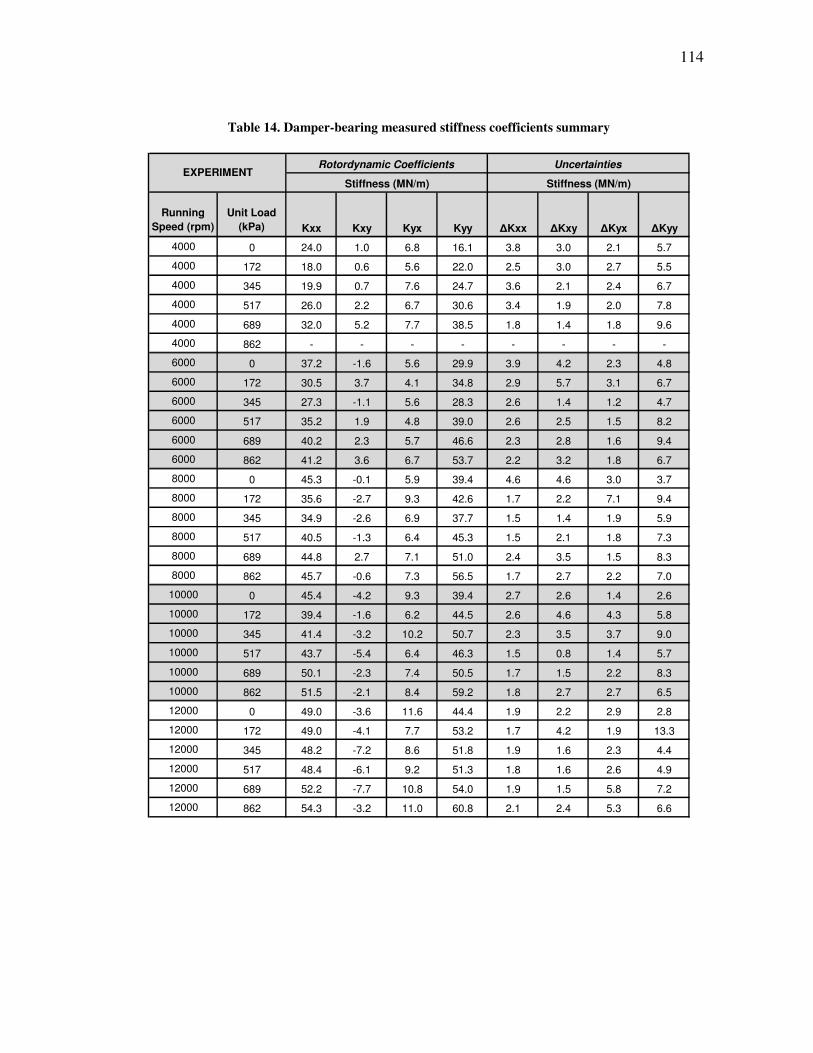
114
Table 14. Damper-bearing measured stiffness coefficients summary
Running
Speed (rpm)
Unit Load
(kPa) Kxx Kxy Kyx Kyy ∆Kxx ∆Kxy ∆Kyx ∆Kyy
4000 0 24.0 1.0 6.8 16.1 3.8 3.0 2.1 5.7
4000 172 18.0 0.6 5.6 22.0 2.5 3.0 2.7 5.5
4000 345 19.9 0.7 7.6 24.7 3.6 2.1 2.4 6.7
4000 517 26.0 2.2 6.7 30.6 3.4 1.9 2.0 7.8
4000 689 32.0 5.2 7.7 38.5 1.8 1.4 1.8 9.6
4000 862 - - - - - - - -
6000 0 37.2 -1.6 5.6 29.9 3.9 4.2 2.3 4.8
6000 172 30.5 3.7 4.1 34.8 2.9 5.7 3.1 6.7
6000 345 27.3 -1.1 5.6 28.3 2.6 1.4 1.2 4.7
6000 517 35.2 1.9 4.8 39.0 2.6 2.5 1.5 8.2
6000 689 40.2 2.3 5.7 46.6 2.3 2.8 1.6 9.4
6000 862 41.2 3.6 6.7 53.7 2.2 3.2 1.8 6.7
8000 0 45.3 -0.1 5.9 39.4 4.6 4.6 3.0 3.7
8000 172 35.6 -2.7 9.3 42.6 1.7 2.2 7.1 9.4
8000 345 34.9 -2.6 6.9 37.7 1.5 1.4 1.9 5.9
8000 517 40.5 -1.3 6.4 45.3 1.5 2.1 1.8 7.3
8000 689 44.8 2.7 7.1 51.0 2.4 3.5 1.5 8.3
8000 862 45.7 -0.6 7.3 56.5 1.7 2.7 2.2 7.0
10000 0 45.4 -4.2 9.3 39.4 2.7 2.6 1.4 2.6
10000 172 39.4 -1.6 6.2 44.5 2.6 4.6 4.3 5.8
10000 345 41.4 -3.2 10.2 50.7 2.3 3.5 3.7 9.0
10000 517 43.7 -5.4 6.4 46.3 1.5 0.8 1.4 5.7
10000 689 50.1 -2.3 7.4 50.5 1.7 1.5 2.2 8.3
10000 862 51.5 -2.1 8.4 59.2 1.8 2.7 2.7 6.5
12000 0 49.0 -3.6 11.6 44.4 1.9 2.2 2.9 2.8
12000 172 49.0 -4.1 7.7 53.2 1.7 4.2 1.9 13.3
12000 345 48.2 -7.2 8.6 51.8 1.9 1.6 2.3 4.4
12000 517 48.4 -6.1 9.2 51.3 1.8 1.6 2.6 4.9
12000 689 52.2 -7.7 10.8 54.0 1.9 1.5 5.8 7.2
12000 862 54.3 -3.2 11.0 60.8 2.1 2.4 5.3 6.6
Stiffness (MN/m) Stiffness (MN/m)
Rotordynamic Coefficients UncertaintiesEXPERIMENT
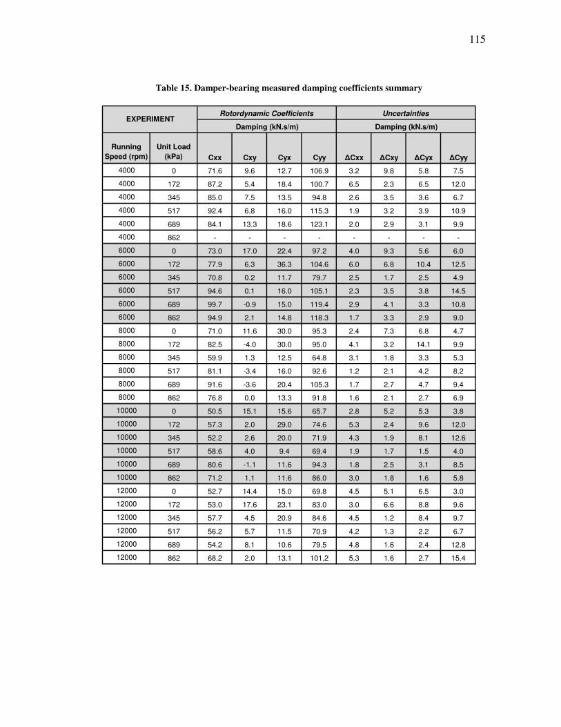
115
Table 15. Damper-bearing measured damping coefficients summary
Running
Speed (rpm)
Unit Load
(kPa) Cxx Cxy Cyx Cyy ∆Cxx ∆Cxy ∆Cyx ∆Cyy
4000 0 71.6 9.6 12.7 106.9 3.2 9.8 5.8 7.5
4000 172 87.2 5.4 18.4 100.7 6.5 2.3 6.5 12.0
4000 345 85.0 7.5 13.5 94.8 2.6 3.5 3.6 6.7
4000 517 92.4 6.8 16.0 115.3 1.9 3.2 3.9 10.9
4000 689 84.1 13.3 18.6 123.1 2.0 2.9 3.1 9.9
4000 862 - - - - - - - -
6000 0 73.0 17.0 22.4 97.2 4.0 9.3 5.6 6.0
6000 172 77.9 6.3 36.3 104.6 6.0 6.8 10.4 12.5
6000 345 70.8 0.2 11.7 79.7 2.5 1.7 2.5 4.9
6000 517 94.6 0.1 16.0 105.1 2.3 3.5 3.8 14.5
6000 689 99.7 -0.9 15.0 119.4 2.9 4.1 3.3 10.8
6000 862 94.9 2.1 14.8 118.3 1.7 3.3 2.9 9.0
8000 0 71.0 11.6 30.0 95.3 2.4 7.3 6.8 4.7
8000 172 82.5 -4.0 30.0 95.0 4.1 3.2 14.1 9.9
8000 345 59.9 1.3 12.5 64.8 3.1 1.8 3.3 5.3
8000 517 81.1 -3.4 16.0 92.6 1.2 2.1 4.2 8.2
8000 689 91.6 -3.6 20.4 105.3 1.7 2.7 4.7 9.4
8000 862 76.8 0.0 13.3 91.8 1.6 2.1 2.7 6.9
10000 0 50.5 15.1 15.6 65.7 2.8 5.2 5.3 3.8
10000 172 57.3 2.0 29.0 74.6 5.3 2.4 9.6 12.0
10000 345 52.2 2.6 20.0 71.9 4.3 1.9 8.1 12.6
10000 517 58.6 4.0 9.4 69.4 1.9 1.7 1.5 4.0
10000 689 80.6 -1.1 11.6 94.3 1.8 2.5 3.1 8.5
10000 862 71.2 1.1 11.6 86.0 3.0 1.8 1.6 5.8
12000 0 52.7 14.4 15.0 69.8 4.5 5.1 6.5 3.0
12000 172 53.0 17.6 23.1 83.0 3.0 6.6 8.8 9.6
12000 345 57.7 4.5 20.9 84.6 4.5 1.2 8.4 9.7
12000 517 56.2 5.7 11.5 70.9 4.2 1.3 2.2 6.7
12000 689 54.2 8.1 10.6 79.5 4.8 1.6 2.4 12.8
12000 862 68.2 2.0 13.1 101.2 5.3 1.6 2.7 15.4
Damping (kN.s/m)
Uncertainties
Damping (kN.s/m)
Rotordynamic CoefficientsEXPERIMENT
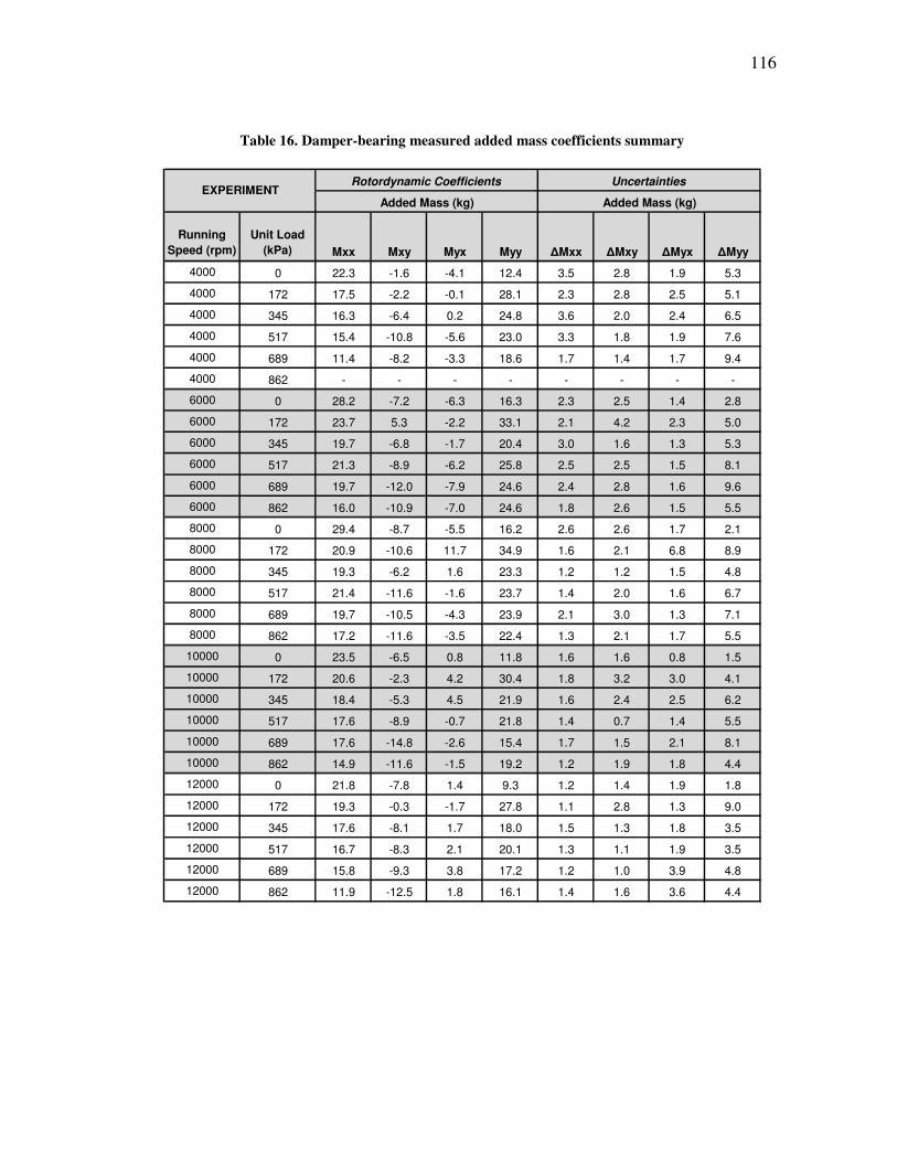
116
Table 16. Damper-bearing measured added mass coefficients summary
Running
Speed (rpm)
Unit Load
(kPa) Mxx Mxy Myx Myy ∆Mxx ∆Mxy ∆Myx ∆Myy
4000 0 22.3 -1.6 -4.1 12.4 3.5 2.8 1.9 5.3
4000 172 17.5 -2.2 -0.1 28.1 2.3 2.8 2.5 5.1
4000 345 16.3 -6.4 0.2 24.8 3.6 2.0 2.4 6.5
4000 517 15.4 -10.8 -5.6 23.0 3.3 1.8 1.9 7.6
4000 689 11.4 -8.2 -3.3 18.6 1.7 1.4 1.7 9.4
4000 862 - - - - - - - -
6000 0 28.2 -7.2 -6.3 16.3 2.3 2.5 1.4 2.8
6000 172 23.7 5.3 -2.2 33.1 2.1 4.2 2.3 5.0
6000 345 19.7 -6.8 -1.7 20.4 3.0 1.6 1.3 5.3
6000 517 21.3 -8.9 -6.2 25.8 2.5 2.5 1.5 8.1
6000 689 19.7 -12.0 -7.9 24.6 2.4 2.8 1.6 9.6
6000 862 16.0 -10.9 -7.0 24.6 1.8 2.6 1.5 5.5
8000 0 29.4 -8.7 -5.5 16.2 2.6 2.6 1.7 2.1
8000 172 20.9 -10.6 11.7 34.9 1.6 2.1 6.8 8.9
8000 345 19.3 -6.2 1.6 23.3 1.2 1.2 1.5 4.8
8000 517 21.4 -11.6 -1.6 23.7 1.4 2.0 1.6 6.7
8000 689 19.7 -10.5 -4.3 23.9 2.1 3.0 1.3 7.1
8000 862 17.2 -11.6 -3.5 22.4 1.3 2.1 1.7 5.5
10000 0 23.5 -6.5 0.8 11.8 1.6 1.6 0.8 1.5
10000 172 20.6 -2.3 4.2 30.4 1.8 3.2 3.0 4.1
10000 345 18.4 -5.3 4.5 21.9 1.6 2.4 2.5 6.2
10000 517 17.6 -8.9 -0.7 21.8 1.4 0.7 1.4 5.5
10000 689 17.6 -14.8 -2.6 15.4 1.7 1.5 2.1 8.1
10000 862 14.9 -11.6 -1.5 19.2 1.2 1.9 1.8 4.4
12000 0 21.8 -7.8 1.4 9.3 1.2 1.4 1.9 1.8
12000 172 19.3 -0.3 -1.7 27.8 1.1 2.8 1.3 9.0
12000 345 17.6 -8.1 1.7 18.0 1.5 1.3 1.8 3.5
12000 517 16.7 -8.3 2.1 20.1 1.3 1.1 1.9 3.5
12000 689 15.8 -9.3 3.8 17.2 1.2 1.0 3.9 4.8
12000 862 11.9 -12.5 1.8 16.1 1.4 1.6 3.6 4.4
Rotordynamic Coefficients Uncertainties
Added Mass (kg) Added Mass (kg)EXPERIMENT
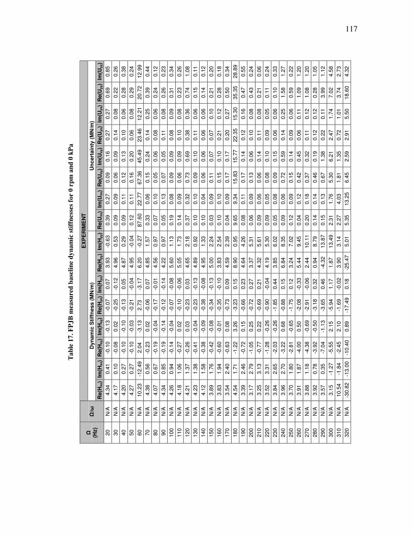
117
Ta
ble
17
. F
PJ
B m
easu
red
ba
seli
ne
dy
na
mic
sti
ffn
ess
es f
or
0 r
pm
an
d 0
kP
a
E
XP
ER
IME
NT
Un
cert
ain
ty (
MN
/m)
Im(U
yy)
0.8
5
0.2
6
0.3
8
0.2
4
12.9
9
0.4
4
0.1
2
0.2
3
0.3
4
0.2
6
1.0
8
0.1
1
0.1
2
0.2
0
0.1
8
0.3
4
28.8
9
0.5
5
0.2
4
0.0
6
0.2
4
0.3
3
1.2
7
0.2
2
1.2
0
1.2
0
1.0
5
1.1
2
4.5
8
2.7
3
4.3
2
Re(U
yy)
0.6
9
0.2
2
0.2
8
0.2
9
20.7
2
0.3
9
0.2
4
0.2
6
0.3
1
0.2
3
0.7
4
0.1
5
0.1
4
0.2
1
0.2
8
0.5
0
35.3
5
0.4
7
0.4
3
0.2
1
0.1
1
0.1
0
1.5
8
0.5
9
1.0
9
1.0
8
0.2
8
3.9
9
7.0
2
3.7
4
18.6
0
Im(U
yx)
0.2
7
0.0
8
0.0
6
0.0
8
12.2
1
0.2
5
0.0
6
0.0
8
0.0
9
0.0
8
0.3
6
0.0
6
0.0
6
0.1
0
0.1
2
0.2
7
15.3
0
0.1
6
0.0
8
0.0
8
0.0
5
0.0
6
0.2
5
0.0
6
0.1
1
0.1
2
0.1
2
0.1
1
1.7
4
1.0
1
5.5
0
Re(U
yx)
0.2
7
0.1
4
0.1
0
0.0
6
23.4
6
0.1
4
0.0
8
0.1
1
0.0
8
0.1
0
0.3
8
0.1
1
0.0
6
0.0
7
0.2
1
0.2
0
22.3
5
0.1
2
0.1
0
0.1
1
0.0
9
0.0
6
0.1
4
0.0
9
0.0
6
0.1
1
0.1
2
0.2
2
2.4
7
0.7
2
2.9
1
Im(U
xy)
0.1
6
0.0
9
0.1
3
0.2
0
45.4
9
0.2
4
0.0
6
0.0
5
0.0
9
0.0
9
0.6
9
0.1
0
0.0
6
0.0
7
0.1
0
0.1
7
15.7
7
0.1
4
0.0
6
0.1
4
0.1
0
0.1
5
0.5
9
0.1
4
0.4
5
0.3
2
0.1
9
1.3
8
6.2
1
1.3
5
2.5
9
Re(U
xy)
0.0
9
0.0
6
0.1
2
0.1
6
67.3
6
0.1
5
0.0
5
0.0
7
0.0
9
0.0
6
0.7
3
0.0
9
0.0
6
0.1
1
0.1
5
0.1
7
15.8
3
0.1
7
0.1
3
0.0
6
0.0
8
0.0
9
0.7
2
0.1
5
0.4
2
0.3
7
0.4
6
0.6
7
5.3
0
1.8
1
6.4
5
Im(U
xx)
0.2
7
0.0
9
0.1
1
0.1
1
22.7
7
0.0
6
0.1
0
0.1
3
0.0
8
0.0
9
0.3
2
0.1
0
0.0
4
0.0
9
0.1
0
0.0
9
9.3
4
0.1
1
0.0
9
0.0
6
0.0
5
0.0
8
0.0
6
0.0
9
0.1
2
0.1
8
0.1
4
0.1
3
1.7
6
4.0
3
13.2
5
Re(U
xx)
0.3
9
0.0
9
0.0
9
0.1
2
87.6
0
0.3
3
0.0
7
0.0
5
0.1
9
0.1
4
0.3
7
0.1
0
0.1
0
0.0
3
0.1
0
0.0
4
9.6
5
0.0
8
0.0
6
0.0
9
0.0
9
0.0
5
0.0
9
0.1
2
0.0
4
0.2
0
0.1
4
0.1
5
2.3
1
2.2
7
5.3
5
Dyn
am
ic S
tiff
ness (
MN
/m)
Im(H
yy)
-0.6
3
0.5
3
0.2
9
-0.0
4
-0.2
7
1.5
7
0.9
7
0.9
7
1.1
3
1.7
3
2.1
8
0.9
2
1.3
3
2.2
4
2.5
4
2.3
9
0.9
5
4.2
6
5.3
1
5.6
1
5.3
0
6.0
2
8.3
5
7.0
2
9.4
5
10.1
1
8.7
9
13.8
7
13.4
9
3.1
4
5.0
1
Re(H
yy)
3.9
3
4.9
6
4.8
7
4.9
5
6.2
0
4.8
5
4.5
6
4.2
2
5.6
0
5.0
5
4.6
5
4.8
9
4.9
5
5.0
0
3.8
3
4.5
9
8.9
0
4.6
4
3.3
7
4.3
2
4.1
9
3.8
5
6.8
4
3.2
4
5.4
4
2.4
4
0.9
4
-4.3
2
1.8
7
3.9
0
-25.4
7
Im(H
yx)
0.0
7
-0.1
2
0.0
5
-0.0
4
-3.1
7
0.0
7
-0.0
1
-0.1
4
-0.0
8
-0.0
6
0.0
3
-0.1
3
-0.0
8
-0.1
3
-0.1
0
0.0
9
0.1
5
0.2
3
0.2
7
0.2
1
-0.0
4
0.4
4
0.1
5
0.1
2
-0.3
3
-0.0
6
0.3
2
0.4
6
1.1
7
-0.0
2
0.1
8
Re(H
yx)
-0.0
7
-0.2
5
-0.1
3
-0.2
1
2.7
3
-0.0
6
-0.1
7
-0.1
2
-0.0
7
-0.1
0
-0.2
3
-0.2
3
-0.3
8
-0.3
4
-0.3
5
-0.7
3
-3.2
3
-0.6
6
-0.7
2
-0.6
9
-0.9
0
-1.8
5
-0.8
8
-1.7
5
-2.0
8
-2.9
1
-3.1
8
-3.6
5
-5.9
4
-1.6
9
-17.4
9
Im(H
xy)
-0.1
3
0.0
2
-0.1
0
-0.0
3
-3.1
3
0.0
2
-0.0
4
-0.1
4
-0.0
4
0.0
2
0.0
3
-0.0
4
-0.0
9
-0.0
8
-0.0
1
0.0
8
3.2
6
0.1
5
0.2
5
0.2
2
-0.2
6
-0.2
6
0.6
8
-0.6
5
0.5
0
-0.6
9
-0.5
0
-1.1
3
2.1
5
2.1
0
0.8
9
Re(H
xy)
-0.1
0
-0.0
8
-0.1
0
-0.1
0
2.0
4
-0.2
3
-0.1
9
-0.1
9
-0.1
4
-0.2
7
-0.2
6
-0.4
1
-0.3
8
-0.4
2
-0.6
0
-0.6
3
-1.2
2
-0.7
2
-1.0
5
-0.7
7
-1.2
8
-2.0
3
-3.2
2
-2.8
1
-4.0
0
-4.3
8
-3.9
2
-7.0
4
-5.5
5
-2.4
5
-10.4
0
Im(H
xx)
0.4
1
0.1
0
0.2
7
0.2
7
-12.4
9
0.5
6
0.6
7
0.8
5
0.9
4
1.0
6
1.3
7
1.3
8
1.5
8
1.7
6
1.9
4
2.4
0
1.7
1
2.4
6
2.7
9
3.1
3
3.3
1
2.6
5
2.7
0
1.8
0
1.8
7
1.1
8
0.7
8
0.3
5
-1.2
7
-1.8
4
-13.0
0
Re(H
xx)
4.3
4
4.1
7
4.2
0
4.2
7
10.2
3
4.3
8
4.0
7
4.3
4
4.2
6
4.1
8
4.2
1
4.2
3
4.1
2
3.8
9
3.8
3
3.5
4
4.5
4
3.3
9
3.1
7
3.2
5
3.5
2
3.8
4
3.9
6
3.7
0
3.9
1
3.8
8
3.9
2
3.5
7
3.1
5
10.5
4
-30.8
2
Ω/ω
N/A
N/A
N/A
N/A
N/A
N/A
N/A
N/A
N/A
N/A
N/A
N/A
N/A
N/A
N/A
N/A
N/A
N/A
N/A
N/A
N/A
N/A
N/A
N/A
N/A
N/A
N/A
N/A
N/A
N/A
N/A
Ω
(Hz)
20
30
40
50
60
70
80
90
100
110
120
130
140
150
160
170
180
190
200
210
220
230
240
250
260
270
280
290
300
310
320
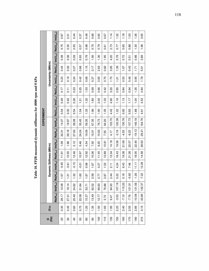
118
Ta
ble
18
. F
PJ
B m
easu
red
dy
na
mic
sti
ffn
esse
s fo
r 4
000
rp
m a
nd
0 k
Pa
EX
PE
RIM
EN
T
Un
cert
ain
ty (
MN
/m)
Im(U
yy)
0.8
7
0.3
1
0.4
4
0.3
7
0.4
8
0.6
8
0.6
5
0.6
7
1.1
4
1.3
2
1.1
8
1.0
3
1.3
6
3.6
0
Re(U
yy)
0.7
5
0.3
5
0.5
5
0.5
7
0.9
8
0.7
5
0.7
9
0.6
1
2.7
3
0.7
7
0.6
5
0.8
8
1.3
0
1.9
6
Im(U
yx)
0.3
8
0.3
8
0.2
9
0.9
3
0.7
8
1.5
6
1.3
6
1.9
5
4.2
0
0.7
8
0.7
2
0.5
1
0.9
8
3.8
9
Re(U
yx)
0.4
4
0.3
2
0.2
7
0.6
6
1.1
5
2.1
7
2.6
3
0.8
2
3.9
5
1.3
9
1.0
7
0.4
3
1.7
1
5.0
1
Im(U
xy)
0.2
3
0.1
9
0.2
4
0.4
2
0.6
8
0.3
7
0.6
5
0.7
0
1.7
0
1.2
1
0.5
3
0.4
6
0.9
5
1.7
9
Re(U
xy)
0.1
7
0.1
1
0.2
3
0.2
5
1.0
3
0.6
9
0.6
6
0.4
2
3.2
0
0.8
5
0.8
4
0.9
4
1.3
5
4.8
4
Im(U
xx)
0.4
9
0.4
2
0.2
6
1.2
1
1.3
2
1.8
0
2.0
2
1.3
3
4.9
0
1.1
6
1.1
3
1.1
7
1.0
4
4.5
3
Re(U
xx)
0.5
4
0.3
0
0.5
4
1.0
4
1.3
3
1.9
6
1.9
0
1.0
5
4.4
5
1.2
2
0.9
5
0.8
3
1.8
8
4.6
1
Dyn
am
ic S
tiff
ness (
MN
/m)
Im(H
yy)
14.0
7
19.9
7
28.0
8
35.4
5
59.3
5
67.3
5
76.7
3
84.2
0
103.7
0
120.3
8
130.7
8
137.7
3
146.1
8
164.7
6
Re(H
yy)
32.3
1
29.1
8
27.6
3
24.2
4
19.0
9
15.5
1
10.6
3
7.5
5
4.1
7
-3.1
9
-4.5
3
-8.2
2
-19.1
2
-29.2
1
Im(H
yx)
1.0
9
1.9
6
2.1
2
0.4
6
4.5
4
7.3
0
9.2
5
10.8
1
14.1
8
19.5
6
21.0
9
22.0
7
22.4
0
28.6
3
Re(H
yx)
11.9
1
12.5
5
12.4
6
10.9
7
12.9
2
10.3
6
11.4
0
12.8
9
13.3
4
18.4
3
19.3
8
21.3
8
18.0
5
14.5
8
Im(H
xy)
-0.4
5
-0.6
1
-0.1
5
-0.0
1
0.9
8
1.6
7
0.2
7
1.0
2
2.1
1
4.2
4
6.4
3
7.4
6
11.1
1
12.2
6
Re(H
xy)
1.6
7
1.2
1
1.3
2
1.6
0
1.8
7
2.5
8
2.7
7
2.8
7
2.4
4
0.2
2
0.1
8
-0.9
2
-1.2
6
-7.2
2
Im(H
xx)
12.0
8
18.1
4
24.8
2
31.8
4
53.7
1
62.0
2
69.9
3
76.8
8
94.5
0
107.1
9
115.2
5
121.9
1
131.5
6
132.3
7
Re(H
xx)
28.1
7
27.3
1
25.4
0
22.0
8
15.3
7
13.4
9
12.7
7
5.7
2
9.4
7
-3.5
3
-7.1
0
-7.7
6
-10.0
9
-33.8
0
Ω/ω
0.3
0
0.4
5
0.6
0
0.7
5
1.2
0
1.3
5
1.5
0
1.6
5
1.9
5
2.2
5
2.4
0
2.5
5
2.8
5
3.1
5
Ω
(Hz)
20
30
40
50
80
90
100
110
130
150
160
170
190
210

119
Ta
ble
19
. F
PJ
B m
easu
red
dy
na
mic
sti
ffn
esse
s fo
r 4
000
rp
m a
nd
17
2 k
Pa
EX
PE
RIM
EN
T
Un
cert
ain
ty (
MN
/m)
Im(U
yy)
0.8
6
0.4
0
0.4
5
0.3
3
10.2
2
0.6
5
0.6
9
0.6
8
1.6
7
1.4
2
0.6
4
0.7
8
0.7
3
5.8
6
1.8
8
1.2
3
3.1
8
Re(U
yy)
0.8
7
0.6
6
0.7
0
0.5
2
6.8
7
1.1
6
0.6
0
0.7
2
1.1
2
1.5
8
2.5
7
0.8
9
1.1
2
5.4
7
1.6
7
1.5
5
5.4
3
Im(U
yx)
0.5
3
0.2
7
0.2
2
0.8
8
2.6
5
1.9
1
1.5
3
1.1
8
1.6
0
0.8
8
0.9
0
0.8
2
1.0
5
8.6
2
1.1
7
4.1
2
5.5
0
Re(U
yx)
0.5
3
0.3
7
0.4
0
0.8
2
1.8
8
1.8
8
1.6
2
0.8
3
2.8
0
1.3
0
1.4
4
0.7
4
0.8
8
6.2
8
1.7
8
2.1
7
3.2
5
Im(U
xy)
0.2
1
0.1
5
0.2
0
0.3
1
1.0
7
0.4
8
0.5
6
0.4
6
2.1
2
0.7
0
0.5
8
0.5
2
0.4
1
4.5
5
0.7
9
0.6
4
2.1
2
Re(U
xy)
0.1
6
0.1
8
0.2
3
0.3
0
1.2
5
0.9
1
0.6
7
0.4
6
0.8
2
0.8
7
0.8
7
0.6
0
0.6
1
4.6
6
0.8
1
2.0
4
1.8
1
Im(U
xx)
0.3
8
0.3
3
0.2
4
0.8
0
1.2
0
1.4
3
1.7
5
1.5
4
2.1
0
1.0
5
1.4
5
0.8
0
0.9
1
5.8
9
1.8
2
3.8
6
5.7
6
Re(U
xx)
0.5
3
0.4
9
0.3
3
1.0
5
1.6
0
2.5
2
1.7
2
1.0
7
2.6
4
0.8
5
1.1
5
0.9
7
1.0
7
7.7
3
1.0
0
3.0
9
3.8
4
Dyn
am
ic S
tiff
ness (
MN
/m)
Im(H
yy)
14.2
3
20.0
0
28.8
6
35.5
6
78.7
1
70.3
7
77.9
4
83.6
9
104.8
3
111.4
1
133.7
0
142.4
8
137.9
0
152.2
5
185.7
0
184.9
1
181.0
1
Re(H
yy)
37.9
1
34.8
0
33.6
6
29.0
2
32.7
5
24.6
3
17.2
0
11.0
6
9.7
6
-15.0
6
2.9
3
-1.3
4
-12.8
1
-26.6
5
-13.0
5
-33.3
4
-45.3
8
Im(H
yx)
0.0
8
0.6
4
1.1
5
1.3
9
7.8
0
4.5
1
12.8
7
12.8
6
16.6
1
17.0
6
18.3
4
22.0
4
21.4
7
26.9
0
30.3
2
30.9
4
22.1
3
Re(H
yx)
14.0
4
13.5
1
13.6
2
12.6
7
12.1
4
9.6
5
12.5
1
13.6
1
20.7
5
19.5
2
23.3
5
24.4
5
25.0
9
29.2
4
28.6
9
28.7
6
17.0
5
Im(H
xy)
-0.1
9
-0.6
2
-0.4
2
-0.3
0
0.2
8
-0.2
1
0.3
4
0.8
0
1.7
9
5.6
3
5.4
6
7.6
5
10.5
0
18.6
7
17.6
3
14.8
4
12.4
3
Re(H
xy)
2.3
7
2.5
3
2.3
5
2.3
3
4.6
2
4.3
1
4.0
4
3.8
7
3.9
0
0.9
7
3.9
6
2.8
6
1.5
0
1.2
3
6.3
5
4.2
3
-0.7
7
Im(H
xx)
11.9
0
17.7
9
24.3
5
31.1
0
52.3
5
60.3
7
67.8
6
75.5
1
91.6
6
104.7
2
112.5
1
119.3
6
127.6
0
138.1
7
132.2
4
138.3
4
125.2
5
Re(H
xx)
31.3
9
30.6
7
28.8
7
26.7
3
19.6
9
18.3
5
17.2
2
11.0
7
12.1
3
1.8
8
-2.2
0
-2.1
5
-6.7
0
-26.5
8
-11.2
0
-43.5
7
-65.7
3
Ω/ω
0.3
0
0.4
5
0.6
0
0.7
5
1.2
0
1.3
5
1.5
0
1.6
5
1.9
5
2.2
5
2.4
0
2.5
5
2.8
5
3.1
5
3.4
5
3.7
5
3.9
0
Ω
(Hz)
20
30
40
50
80
90
100
110
130
150
160
170
190
210
230
250
260
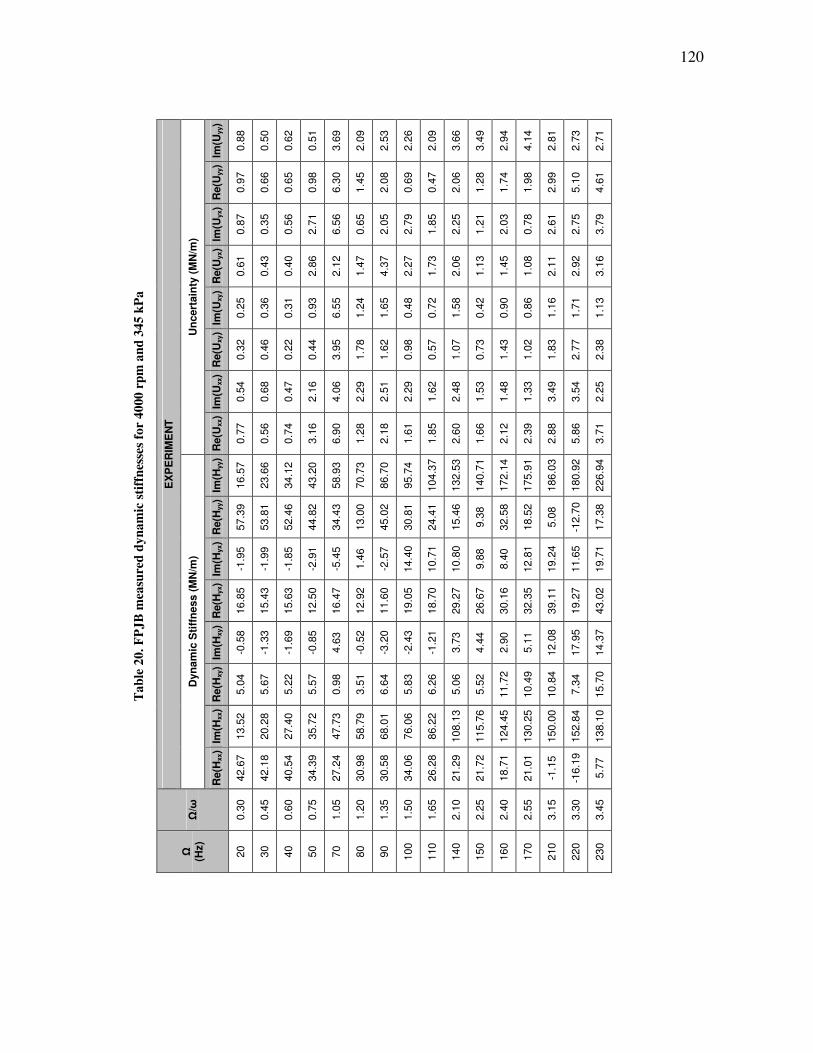
120
Ta
ble
20
. F
PJ
B m
easu
red
dy
na
mic
sti
ffn
esse
s fo
r 4
000
rp
m a
nd
34
5 k
Pa
EX
PE
RIM
EN
T
Un
cert
ain
ty (
MN
/m)
Im(U
yy)
0.8
8
0.5
0
0.6
2
0.5
1
3.6
9
2.0
9
2.5
3
2.2
6
2.0
9
3.6
6
3.4
9
2.9
4
4.1
4
2.8
1
2.7
3
2.7
1
Re(U
yy)
0.9
7
0.6
6
0.6
5
0.9
8
6.3
0
1.4
5
2.0
8
0.6
9
0.4
7
2.0
6
1.2
8
1.7
4
1.9
8
2.9
9
5.1
0
4.6
1
Im(U
yx)
0.8
7
0.3
5
0.5
6
2.7
1
6.5
6
0.6
5
2.0
5
2.7
9
1.8
5
2.2
5
1.2
1
2.0
3
0.7
8
2.6
1
2.7
5
3.7
9
Re(U
yx)
0.6
1
0.4
3
0.4
0
2.8
6
2.1
2
1.4
7
4.3
7
2.2
7
1.7
3
2.0
6
1.1
3
1.4
5
1.0
8
2.1
1
2.9
2
3.1
6
Im(U
xy)
0.2
5
0.3
6
0.3
1
0.9
3
6.5
5
1.2
4
1.6
5
0.4
8
0.7
2
1.5
8
0.4
2
0.9
0
0.8
6
1.1
6
1.7
1
1.1
3
Re(U
xy)
0.3
2
0.4
6
0.2
2
0.4
4
3.9
5
1.7
8
1.6
2
0.9
8
0.5
7
1.0
7
0.7
3
1.4
3
1.0
2
1.8
3
2.7
7
2.3
8
Im(U
xx)
0.5
4
0.6
8
0.4
7
2.1
6
4.0
6
2.2
9
2.5
1
2.2
9
1.6
2
2.4
8
1.5
3
1.4
8
1.3
3
3.4
9
3.5
4
2.2
5
Re(U
xx)
0.7
7
0.5
6
0.7
4
3.1
6
6.9
0
1.2
8
2.1
8
1.6
1
1.8
5
2.6
0
1.6
6
2.1
2
2.3
9
2.8
8
5.8
6
3.7
1
Dyn
am
ic S
tiff
ness (
MN
/m)
Im(H
yy)
16.5
7
23.6
6
34.1
2
43.2
0
58.9
3
70.7
3
86.7
0
95.7
4
104.3
7
132.5
3
140.7
1
172.1
4
175.9
1
186.0
3
180.9
2
226.9
4
Re(H
yy)
57.3
9
53.8
1
52.4
6
44.8
2
34.4
3
13.0
0
45.0
2
30.8
1
24.4
1
15.4
6
9.3
8
32.5
8
18.5
2
5.0
8
-12.7
0
17.3
8
Im(H
yx)
-1.9
5
-1.9
9
-1.8
5
-2.9
1
-5.4
5
1.4
6
-2.5
7
14.4
0
10.7
1
10.8
0
9.8
8
8.4
0
12.8
1
19.2
4
11.6
5
19.7
1
Re(H
yx)
16.8
5
15.4
3
15.6
3
12.5
0
16.4
7
12.9
2
11.6
0
19.0
5
18.7
0
29.2
7
26.6
7
30.1
6
32.3
5
39.1
1
19.2
7
43.0
2
Im(H
xy)
-0.5
8
-1.3
3
-1.6
9
-0.8
5
4.6
3
-0.5
2
-3.2
0
-2.4
3
-1.2
1
3.7
3
4.4
4
2.9
0
5.1
1
12.0
8
17.9
5
14.3
7
Re(H
xy)
5.0
4
5.6
7
5.2
2
5.5
7
0.9
8
3.5
1
6.6
4
5.8
3
6.2
6
5.0
6
5.5
2
11.7
2
10.4
9
10.8
4
7.3
4
15.7
0
Im(H
xx)
13.5
2
20.2
8
27.4
0
35.7
2
47.7
3
58.7
9
68.0
1
76.0
6
86.2
2
108.1
3
115.7
6
124.4
5
130.2
5
150.0
0
152.8
4
138.1
0
Re(H
xx)
42.6
7
42.1
8
40.5
4
34.3
9
27.2
4
30.9
8
30.5
8
34.0
6
26.2
8
21.2
9
21.7
2
18.7
1
21.0
1
-1.1
5
-16.1
9
5.7
7
Ω/ω
0.3
0
0.4
5
0.6
0
0.7
5
1.0
5
1.2
0
1.3
5
1.5
0
1.6
5
2.1
0
2.2
5
2.4
0
2.5
5
3.1
5
3.3
0
3.4
5
Ω
(Hz)
20
30
40
50
70
80
90
100
110
140
150
160
170
210
220
230
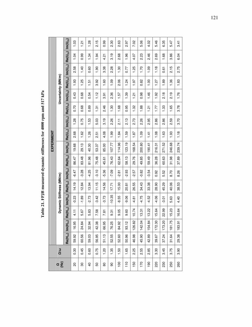
121
Ta
ble
21
. F
PJ
B m
easu
red
dy
na
mic
sti
ffn
esse
s fo
r 4
000
rp
m a
nd
51
7 k
Pa
E
XP
ER
IME
NT
Un
cert
ain
ty (
MN
/m)
Im(U
yy)
1.0
3
1.2
1
1.2
8
2.1
5
0.9
9
2.3
0
2.6
3
2.9
7
7.0
2
5.0
6
4.0
2
5.4
6
6.3
5
5.4
7
3.4
1
Re(U
yy)
1.0
4
0.9
9
1.3
4
1.9
4
4.2
1
3.1
9
2.6
8
1.9
6
4.0
7
2.2
3
2.4
6
2.6
9
1.6
8
3.8
6
6.0
4
Im(U
yx)
2.5
8
1.4
0
0.6
0
1.9
0
3.3
8
2.2
8
1.3
0
0.7
7
1.2
5
1.7
0
1.0
9
1.1
8
0.6
1
2.1
5
2.7
5
Re(U
yx)
1.9
3
1.2
5
1.5
1
3.9
2
1.6
0
1.0
9
2.0
6
1.2
4
1.9
7
0.8
2
1.0
0
1.2
7
1.8
9
1.3
6
1.8
3
Im(U
xy)
0.4
3
0.6
8
0.5
4
1.1
2
3.9
1
2.3
6
1.5
7
1.3
9
1.2
1
0.9
8
1.4
6
1.9
2
2.1
8
2.1
9
1.7
6
Re(U
xy)
0.7
0
0.6
8
0.8
9
1.3
1
2.4
6
1.3
0
1.6
8
0.9
5
1.3
2
1.8
8
1.2
1
1.7
7
1.3
3
1.6
5
3.7
8
Im(U
xx)
1.2
8
0.7
5
1.5
3
5.0
3
3.1
9
2.2
6
2.1
1
2.1
3
2.7
3
2.2
6
2.9
5
2.8
6
2.8
6
2.5
9
3.7
0
Re(U
xx)
2.6
8
1.6
2
1.2
6
2.5
1
4.0
8
1.9
9
1.8
4
1.5
9
1.8
7
1.0
9
1.4
1
1.0
8
1.6
3
1.9
3
1.1
8
Dyn
am
ic S
tiff
ness (
MN
/m)
Im(H
yy)
19.6
8
29.1
3
40.3
0
53.3
7
85.0
0
107.7
7
114.9
6
123.1
9
168.5
4
200.8
0
190.4
1
216.3
1
271.5
2
246.6
8
239.7
4
Re(H
yy)
86.4
7
83.4
8
81.9
6
75.4
8
45.6
1
76.4
3
62.6
4
58.1
3
29.7
6
49.8
5
59.4
9
36.2
8
60.6
3
31.9
8
37.8
9
Im(H
yx)
-6.4
7
-3.2
8
-4.2
5
-3.1
0
-5.3
6
-7.0
9
-2.8
1
-2.9
3
-2.5
7
-0.8
2
-3.5
4
0.9
2
5.5
2
8.7
0
8.2
6
Re(H
yx)
14.1
9
12.8
4
13.9
4
11.1
5
14.5
6
17.7
1
15.0
0
20.8
1
26.5
5
34.4
3
33.3
8
28.9
0
45.2
9
40.0
6
38.5
3
Im(H
xy)
-0.2
3
-1.8
9
-2.7
3
-3.4
2
-3.7
3
-10.3
5
-8.5
5
-9.0
6
-4.8
1
-4.7
5
-4.5
2
-4.0
6
-3.0
1
5.6
3
4.4
0
Re(H
xy)
4.1
1
5.6
7
5.8
3
7.5
8
7.8
1
9.3
1
9.0
5
9.6
0
10.7
4
13.3
1
13.2
2
15.6
4
22.9
9
15.2
3
16.6
4
Im(H
xx)
16.9
5
24.8
4
32.9
4
42.3
8
66.9
5
76.2
5
84.9
2
93.1
2
126.8
2
142.0
4
154.8
4
172.3
0
173.2
0
181.7
5
183.9
1
Re(H
xx)
59.9
2
60.5
6
59.0
3
56.9
5
51.1
3
52.5
5
52.6
0
50.9
6
46.9
8
45.9
0
42.8
9
39.6
7
37.2
4
31.6
4
29.3
8
Ω/ω
0.3
0
0.4
5
0.6
0
0.7
5
1.2
0
1.3
5
1.5
0
1.6
5
2.2
5
2.5
5
2.8
5
3.3
0
3.4
5
3.7
5
3.9
0
Ω
(Hz)
20
30
40
50
80
90
100
110
150
170
190
220
230
250
260
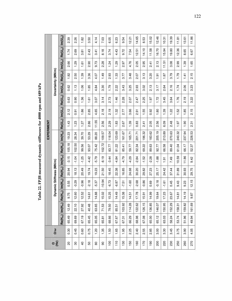
122
Ta
ble
22
. F
PJ
B m
easu
red
dy
na
mic
sti
ffn
esse
s fo
r 4
000
rp
m a
nd
68
9 k
Pa
EX
PE
RIM
EN
T
Un
cert
ain
ty (
MN
/m)
Im(U
yy)
2.3
9
2.2
6
1.8
2
3.5
0
4.1
4
7.0
3
6.0
5
6.2
3
9.5
4
12.2
1
14.6
5
8.5
3
15.0
2
12.4
6
10.3
1
19.3
9
11.8
1
13.6
1
11.8
6
Re(U
yy)
1.7
4
2.6
9
3.8
1
2.4
3
3.4
1
8.1
8
3.7
4
4.4
3
9.7
2
7.5
4
12.5
1
14.1
0
11.5
8
16.7
0
15.9
4
19.8
0
12.3
6
8.6
5
6.6
7
Im(U
yx)
2.6
6
1.2
9
1.6
1
2.9
0
9.7
3
2.2
8
1.2
4
1.2
9
2.9
7
4.7
6
2.0
5
2.9
5
2.4
1
2.1
3
11.5
1
3.0
8
2.9
9
1.3
9
1.6
5
Re(U
yx)
1.8
2
2.5
0
1.3
9
3.3
6
4.0
7
1.4
9
2.9
3
1.3
3
3.7
7
3.4
8
2.0
7
3.1
3
3.2
0
1.9
1
1.8
7
3.7
9
1.7
9
1.4
1
2.1
5
Im(U
xy)
0.6
2
1.1
3
1.0
6
1.8
5
4.8
4
3.3
0
1.7
9
2.2
2
3.4
3
3.2
5
2.9
3
3.0
2
2.1
3
3.1
7
2.6
4
2.1
6
1.7
4
2.0
6
3.2
3
Re(U
xy)
0.6
3
0.9
0
1.3
6
1.6
1
3.0
7
3.1
4
2.7
3
1.4
6
2.2
8
2.0
7
2.4
7
2.2
5
1.9
7
1.7
2
3.4
5
3.6
4
1.7
6
2.1
9
3.2
2
Im(U
xx)
2.1
2
0.9
1
1.8
6
2.8
5
4.6
5
2.1
8
2.1
9
1.3
2
2.7
7
3.6
6
2.9
1
1.5
5
0.9
2
1.8
0
1.3
9
1.2
2
1.5
2
1.8
5
2.1
5
Re(U
xx)
1.4
3
1.2
3
1.2
7
2.8
6
11.5
5
2.5
6
2.2
9
1.8
3
2.6
7
1.3
9
0.8
3
2.4
1
2.0
5
2.5
6
6.0
9
2.4
8
1.9
7
1.9
0
2.3
1
Dyn
am
ic S
tiff
ness (
MN
/m)
Im(H
yy)
19.2
3
28.3
4
39.7
0
53.2
9
88.2
0
109.5
7
118.0
4
123.6
9
161.6
7
165.7
1
201.7
1
196.3
2
183.6
2
205.1
9
213.8
9
270.6
3
240.3
2
237.9
4
228.5
3
Re(H
yy)
105.1
8
102.5
0
99.5
6
93.0
7
75.4
2
102.7
2
83.7
7
81.2
2
85.4
1
59.7
7
82.3
4
69.2
2
89.6
3
92.7
7
66.5
8
89.4
0
61.0
4
66.1
7
52.3
7
Im(H
yx)
-3.1
5
-1.0
4
-1.2
5
-4.4
2
-5.7
9
-8.1
9
-3.4
4
-4.8
4
-4.7
9
-4.2
9
-2.8
4
-1.5
2
-2.2
8
-1.8
8
1.9
1
7.4
9
10.5
9
11.8
6
9.4
2
Re(H
yx)
20.9
4
18.1
3
20.4
9
19.7
4
19.2
3
21.5
0
18.4
5
22.3
8
16.8
5
24.6
8
30.2
0
29.8
2
27.2
3
25.1
7
24.4
2
37.4
4
31.8
9
30.9
3
29.7
5
Im(H
xy)
0.5
5
-0.2
9
-0.9
6
-2.1
8
-5.3
7
-10.9
4
-6.7
3
-6.8
7
-7.5
1
-1.6
0
-2.6
8
-0.8
6
0.6
9
-0.1
8
-1.6
1
0.4
5
9.4
3
9.2
3
12.1
5
Re(H
xy)
9.7
5
12.6
0
12.5
2
14.6
1
14.8
8
15.0
2
15.2
5
14.4
9
15.3
8
14.5
1
17.7
8
15.9
1
14.9
9
19.6
4
17.2
3
23.6
7
14.8
1
14.1
9
9.8
7
Im(H
xx)
12.4
9
22.1
0
27.9
2
40.4
8
63.6
5
71.5
3
79.5
0
85.5
1
103.9
2
114.2
8
122.6
2
126.1
5
136.8
5
146.0
7
150.9
5
152.2
9
158.3
1
159.8
2
161.6
9
Re(H
xx)
65.4
9
69.6
9
67.1
9
65.4
5
65.0
5
65.8
1
68.6
6
67.6
7
67.3
1
66.2
9
68.9
8
67.0
8
65.0
0
65.1
2
63.0
3
58.2
4
53.7
4
51.9
6
49.9
4
Ω/ω
0.3
0
0.4
5
0.6
0
0.7
5
1.2
0
1.3
5
1.5
0
1.6
5
1.9
5
2.2
5
2.4
0
2.5
5
2.8
5
3.0
0
3.3
0
3.4
5
3.7
5
3.9
0
4.0
5
Ω
(Hz)
20
30
40
50
80
90
100
110
130
150
160
170
190
200
220
230
250
260
270

123
Ta
ble
23
. F
PJ
B m
easu
red
dy
na
mic
sti
ffn
esse
s fo
r 6
000
rp
m a
nd
0 k
Pa
EX
PE
RIM
EN
T
Un
cert
ain
ty (
MN
/m)
Im(U
yy)
0.8
7
0.3
1
0.4
4
0.3
7
0.4
8
0.6
8
0.6
5
0.6
7
1.1
4
1.3
2
1.1
8
1.0
3
1.3
6
3.6
0
Re(U
yy)
0.7
5
0.3
5
0.5
5
0.5
7
0.9
8
0.7
5
0.7
9
0.6
1
2.7
3
0.7
7
0.6
5
0.8
8
1.3
0
1.9
6
Im(U
yx)
0.3
8
0.3
8
0.2
9
0.9
3
0.7
8
1.5
6
1.3
6
1.9
5
4.2
0
0.7
8
0.7
2
0.5
1
0.9
8
3.8
9
Re(U
yx)
0.4
4
0.3
2
0.2
7
0.6
6
1.1
5
2.1
7
2.6
3
0.8
2
3.9
5
1.3
9
1.0
7
0.4
3
1.7
1
5.0
1
Im(U
xy)
0.2
3
0.1
9
0.2
4
0.4
2
0.6
8
0.3
7
0.6
5
0.7
0
1.7
0
1.2
1
0.5
3
0.4
6
0.9
5
1.7
9
Re(U
xy)
0.1
7
0.1
1
0.2
3
0.2
5
1.0
3
0.6
9
0.6
6
0.4
2
3.2
0
0.8
5
0.8
4
0.9
4
1.3
5
4.8
4
Im(U
xx)
0.4
9
0.4
2
0.2
6
1.2
1
1.3
2
1.8
0
2.0
2
1.3
3
4.9
0
1.1
6
1.1
3
1.1
7
1.0
4
4.5
3
Re(U
xx)
0.5
4
0.3
0
0.5
4
1.0
4
1.3
3
1.9
6
1.9
0
1.0
5
4.4
5
1.2
2
0.9
5
0.8
3
1.8
8
4.6
1
Dyn
am
ic S
tiff
ness (
MN
/m)
Im(H
yy)
14.0
7
19.9
7
28.0
8
35.4
5
59.3
5
67.3
5
76.7
3
84.2
0
103.7
0
120.3
8
130.7
8
137.7
3
146.1
8
164.7
6
Re(H
yy)
32.3
1
29.1
8
27.6
3
24.2
4
19.0
9
15.5
1
10.6
3
7.5
5
4.1
7
-3.1
9
-4.5
3
-8.2
2
-19.1
2
-29.2
1
Im(H
yx)
1.0
9
1.9
6
2.1
2
0.4
6
4.5
4
7.3
0
9.2
5
10.8
1
14.1
8
19.5
6
21.0
9
22.0
7
22.4
0
28.6
3
Re(H
yx)
11.9
1
12.5
5
12.4
6
10.9
7
12.9
2
10.3
6
11.4
0
12.8
9
13.3
4
18.4
3
19.3
8
21.3
8
18.0
5
14.5
8
Im(H
xy)
-0.4
5
-0.6
1
-0.1
5
-0.0
1
0.9
8
1.6
7
0.2
7
1.0
2
2.1
1
4.2
4
6.4
3
7.4
6
11.1
1
12.2
6
Re(H
xy)
1.6
7
1.2
1
1.3
2
1.6
0
1.8
7
2.5
8
2.7
7
2.8
7
2.4
4
0.2
2
0.1
8
-0.9
2
-1.2
6
-7.2
2
Im(H
xx)
12.0
8
18.1
4
24.8
2
31.8
4
53.7
1
62.0
2
69.9
3
76.8
8
94.5
0
107.1
9
115.2
5
121.9
1
131.5
6
132.3
7
Re(H
xx)
28.1
7
27.3
1
25.4
0
22.0
8
15.3
7
13.4
9
12.7
7
5.7
2
9.4
7
-3.5
3
-7.1
0
-7.7
6
-10.0
9
-33.8
0
Ω/ω
0.3
0
0.4
5
0.6
0
0.7
5
1.2
0
1.3
5
1.5
0
1.6
5
1.9
5
2.2
5
2.4
0
2.5
5
2.8
5
3.1
5
Ω
(Hz)
20
30
40
50
80
90
100
110
130
150
160
170
190
210
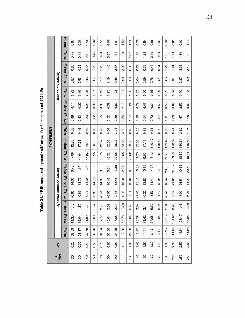
124
Ta
ble
24
. F
PJ
B m
easu
red
dy
na
mic
sti
ffn
esse
s fo
r 6
000
rp
m a
nd
17
2 k
Pa
EX
PE
RIM
EN
T
Un
cert
ain
ty (
MN
/m)
Im(U
yy)
0.8
7
0.3
6
0.4
5
0.3
2
0.5
3
4.0
9
1.0
1
1.5
9
1.1
0
0.7
6
0.8
4
0.8
8
0.9
4
0.9
2
0.9
3
0.9
3
1.7
7
Re(U
yy)
0.7
5
0.4
3
0.5
1
0.4
5
0.6
8
5.8
7
1.5
4
1.2
8
1.3
2
1.2
5
1.2
3
2.4
6
0.9
0
1.3
1
1.3
3
1.1
6
1.9
1
Im(U
yx)
0.8
6
0.3
5
0.3
7
1.2
8
1.2
3
1.4
5
2.5
7
3.0
3
2.3
9
0.7
2
0.3
6
0.4
8
0.5
1
1.2
7
1.8
1
3.3
8
3.4
2
Re(U
yx)
0.8
7
0.5
3
0.4
3
0.6
7
0.5
7
1.1
9
2.4
6
2.9
0
2.2
0
0.6
4
0.5
9
0.7
8
0.5
1
0.6
5
0.8
1
2.8
7
2.0
9
Im(U
xy)
0.2
3
0.1
9
0.2
5
0.2
7
0.4
2
0.9
5
1.2
3
1.3
1
1.3
6
0.6
3
0.5
0
0.6
5
0.5
9
0.6
9
0.6
6
0.7
0
1.9
8
Re(U
xy)
0.1
4
0.2
2
0.2
9
0.3
2
0.3
6
0.5
2
0.8
2
2.1
2
1.2
4
0.7
9
0.4
7
0.6
4
0.5
3
0.5
8
0.6
3
2.5
2
0.8
2
Im(U
xx)
0.4
8
0.5
3
0.3
3
0.8
2
0.7
5
0.3
2
2.3
9
3.5
4
1.7
7
1.2
0
0.5
4
0.7
2
0.8
7
1.1
1
2.0
0
4.6
7
4.0
5
Re(U
xx)
0.5
8
0.4
5
0.3
9
0.5
6
0.7
0
0.8
4
3.0
1
3.3
0
2.4
5
0.8
5
0.8
8
0.8
1
0.5
9
0.9
9
0.9
1
2.6
2
4.1
6
Dyn
am
ic S
tiff
ness (
MN
/m)
Im(H
yy)
12.8
0
17.3
5
24.4
0
30.1
0
42.0
2
62.3
5
58.2
7
63.8
6
83.6
2
85.0
3
87.1
9
110.1
2
108.4
7
109.4
2
150.0
8
150.6
4
150.5
2
Re(H
yy)
47.0
6
44.9
4
43.6
3
39.5
5
33.7
5
45.5
2
32.0
6
19.0
5
20.6
2
11.2
5
-0.9
0
15.1
3
6.1
8
-9.3
3
-13.7
3
-38.5
2
-49.4
1
Im(H
yx)
0.7
8
1.1
7
1.2
5
1.9
6
3.0
5
5.8
4
-2.3
8
2.2
7
6.8
9
10.0
2
10.1
6
14.0
7
17.0
6
20.3
6
31.0
9
30.5
3
20.6
4
Re(H
yx)
14.0
5
13.7
9
14.3
5
14.7
6
14.3
7
16.4
2
13.4
8
18.3
4
19.0
2
15.1
3
13.8
7
14.4
1
15.0
1
16.4
4
22.6
2
25.5
1
14.2
2
Im(H
xy)
-0.6
3
-0.8
9
-0.7
9
-0.8
9
-0.4
6
-0.6
5
2.6
8
4.9
6
0.0
1
-1.4
3
-0.2
3
-1.5
9
-1.1
7
-0.4
0
3.0
8
-1.9
0
-6.2
6
Re(H
xy)
1.4
0
1.5
7
1.3
0
1.6
7
2.4
8
2.6
9
2.3
1
-3.3
9
5.4
2
3.6
4
3.1
4
5.8
0
3.9
4
2.0
4
0.9
3
1.4
8
-2.2
0
Im(H
xx)
11.3
5
15.9
4
21.6
0
26.0
3
37.7
7
43.6
4
47.0
8
56.7
8
70.3
4
76.5
2
81.4
2
87.6
5
92.3
4
99.1
5
106.0
2
105.4
7
85.8
5
Re(H
xx)
38.6
9
38.6
7
37.6
5
36.7
0
32.5
4
30.5
6
24.2
5
17.2
6
20.6
8
13.4
5
11.0
1
6.4
2
4.1
3
-2.9
5
-13.0
3
-44.5
1
-65.9
3
Ω/ω
0.2
0
0.3
0
0.4
0
0.5
0
0.7
0
0.8
0
0.9
0
1.1
0
1.3
0
1.4
0
1.5
0
1.6
0
1.7
0
1.9
0
2.3
0
2.5
0
2.6
0
Ω
(Hz)
20
30
40
50
70
80
90
110
130
140
150
160
170
190
230
250
260
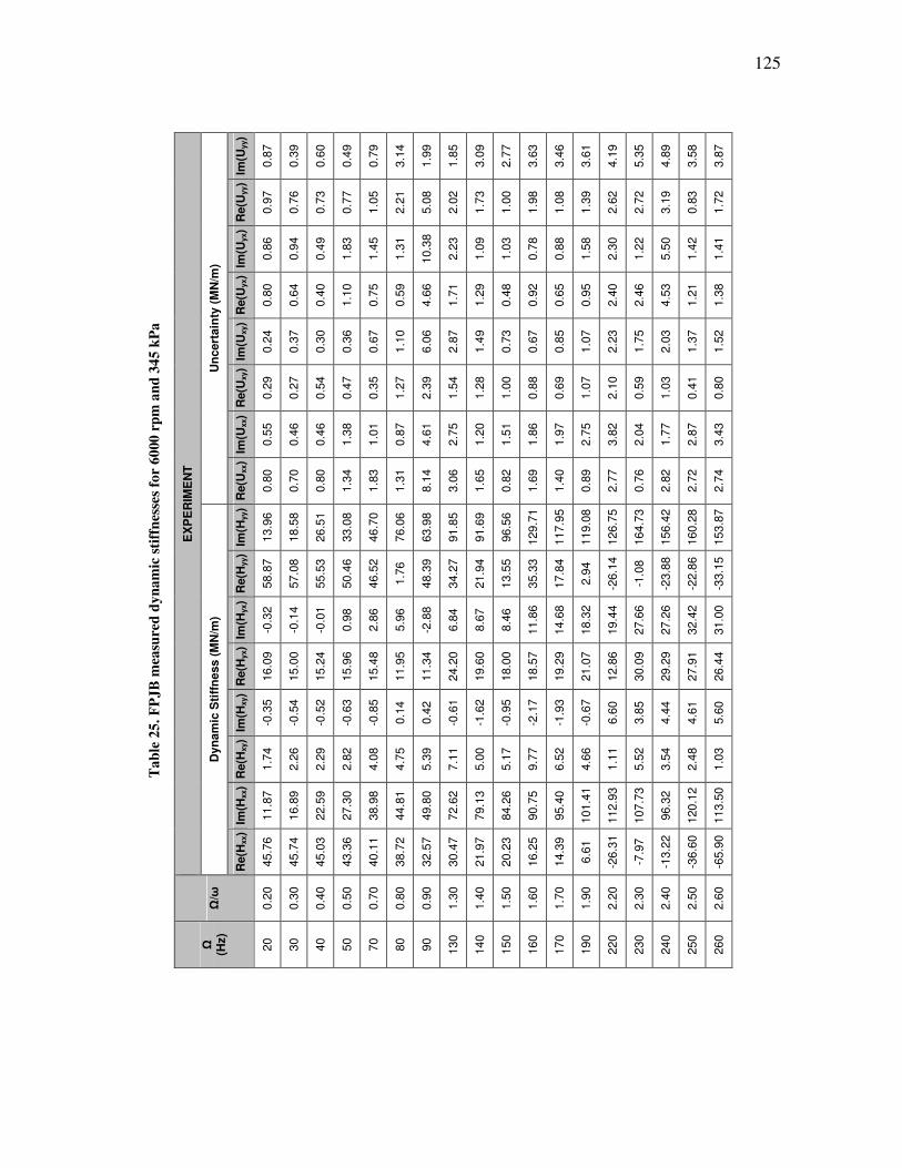
125
Ta
ble
25
. F
PJ
B m
easu
red
dy
na
mic
sti
ffn
esse
s fo
r 6
000
rp
m a
nd
34
5 k
Pa
EX
PE
RIM
EN
T
Un
cert
ain
ty (
MN
/m)
Im(U
yy)
0.8
7
0.3
9
0.6
0
0.4
9
0.7
9
3.1
4
1.9
9
1.8
5
3.0
9
2.7
7
3.6
3
3.4
6
3.6
1
4.1
9
5.3
5
4.8
9
3.5
8
3.8
7
Re(U
yy)
0.9
7
0.7
6
0.7
3
0.7
7
1.0
5
2.2
1
5.0
8
2.0
2
1.7
3
1.0
0
1.9
8
1.0
8
1.3
9
2.6
2
2.7
2
3.1
9
0.8
3
1.7
2
Im(U
yx)
0.8
6
0.9
4
0.4
9
1.8
3
1.4
5
1.3
1
10.3
8
2.2
3
1.0
9
1.0
3
0.7
8
0.8
8
1.5
8
2.3
0
1.2
2
5.5
0
1.4
2
1.4
1
Re(U
yx)
0.8
0
0.6
4
0.4
0
1.1
0
0.7
5
0.5
9
4.6
6
1.7
1
1.2
9
0.4
8
0.9
2
0.6
5
0.9
5
2.4
0
2.4
6
4.5
3
1.2
1
1.3
8
Im(U
xy)
0.2
4
0.3
7
0.3
0
0.3
6
0.6
7
1.1
0
6.0
6
2.8
7
1.4
9
0.7
3
0.6
7
0.8
5
1.0
7
2.2
3
1.7
5
2.0
3
1.3
7
1.5
2
Re(U
xy)
0.2
9
0.2
7
0.5
4
0.4
7
0.3
5
1.2
7
2.3
9
1.5
4
1.2
8
1.0
0
0.8
8
0.6
9
1.0
7
2.1
0
0.5
9
1.0
3
0.4
1
0.8
0
Im(U
xx)
0.5
5
0.4
6
0.4
6
1.3
8
1.0
1
0.8
7
4.6
1
2.7
5
1.2
0
1.5
1
1.8
6
1.9
7
2.7
5
3.8
2
2.0
4
1.7
7
2.8
7
3.4
3
Re(U
xx)
0.8
0
0.7
0
0.8
0
1.3
4
1.8
3
1.3
1
8.1
4
3.0
6
1.6
5
0.8
2
1.6
9
1.4
0
0.8
9
2.7
7
0.7
6
2.8
2
2.7
2
2.7
4
Dyn
am
ic S
tiff
ness (
MN
/m)
Im(H
yy)
13.9
6
18.5
8
26.5
1
33.0
8
46.7
0
76.0
6
63.9
8
91.8
5
91.6
9
96.5
6
129.7
1
117.9
5
119.0
8
126.7
5
164.7
3
156.4
2
160.2
8
153.8
7
Re(H
yy)
58.8
7
57.0
8
55.5
3
50.4
6
46.5
2
1.7
6
48.3
9
34.2
7
21.9
4
13.5
5
35.3
3
17.8
4
2.9
4
-26.1
4
-1.0
8
-23.8
8
-22.8
6
-33.1
5
Im(H
yx)
-0.3
2
-0.1
4
-0.0
1
0.9
8
2.8
6
5.9
6
-2.8
8
6.8
4
8.6
7
8.4
6
11.8
6
14.6
8
18.3
2
19.4
4
27.6
6
27.2
6
32.4
2
31.0
0
Re(H
yx)
16.0
9
15.0
0
15.2
4
15.9
6
15.4
8
11.9
5
11.3
4
24.2
0
19.6
0
18.0
0
18.5
7
19.2
9
21.0
7
12.8
6
30.0
9
29.2
9
27.9
1
26.4
4
Im(H
xy)
-0.3
5
-0.5
4
-0.5
2
-0.6
3
-0.8
5
0.1
4
0.4
2
-0.6
1
-1.6
2
-0.9
5
-2.1
7
-1.9
3
-0.6
7
6.6
0
3.8
5
4.4
4
4.6
1
5.6
0
Re(H
xy)
1.7
4
2.2
6
2.2
9
2.8
2
4.0
8
4.7
5
5.3
9
7.1
1
5.0
0
5.1
7
9.7
7
6.5
2
4.6
6
1.1
1
5.5
2
3.5
4
2.4
8
1.0
3
Im(H
xx)
11.8
7
16.8
9
22.5
9
27.3
0
38.9
8
44.8
1
49.8
0
72.6
2
79.1
3
84.2
6
90.7
5
95.4
0
101.4
1
112.9
3
107.7
3
96.3
2
120.1
2
113.5
0
Re(H
xx)
45.7
6
45.7
4
45.0
3
43.3
6
40.1
1
38.7
2
32.5
7
30.4
7
21.9
7
20.2
3
16.2
5
14.3
9
6.6
1
-26.3
1
-7.9
7
-13.2
2
-36.6
0
-65.9
0
Ω/ω
0.2
0
0.3
0
0.4
0
0.5
0
0.7
0
0.8
0
0.9
0
1.3
0
1.4
0
1.5
0
1.6
0
1.7
0
1.9
0
2.2
0
2.3
0
2.4
0
2.5
0
2.6
0
Ω
(Hz)
20
30
40
50
70
80
90
130
140
150
160
170
190
220
230
240
250
260

126
Ta
ble
26
. F
PJ
B m
easu
red
dy
na
mic
sti
ffn
esse
s fo
r 6
000
rp
m a
nd
51
7 k
Pa
EX
PE
RIM
EN
T
Un
cert
ain
ty (
MN
/m)
Im(U
yy)
0.9
1
1.1
4
1.3
0
1.2
2
1.7
9
1.7
1
3.0
8
3.3
9
2.6
9
3.2
4
2.4
9
3.2
0
3.9
7
5.2
6
4.1
1
4.7
4
9.0
2
4.4
2
3.8
8
3.3
7
5.9
5
Re(U
yy)
1.2
6
1.4
1
1.5
8
1.1
3
1.4
4
1.1
6
2.7
7
3.4
6
1.9
8
1.4
3
1.8
1
1.9
5
3.2
8
2.9
5
2.0
6
2.1
3
5.8
3
2.2
7
1.7
7
2.2
6
2.3
5
Im(U
yx)
2.2
4
1.2
6
1.0
0
0.7
2
1.1
6
0.8
7
2.1
8
2.6
2
1.5
0
0.6
6
0.9
1
0.8
5
1.2
8
2.2
3
1.6
0
1.1
7
2.4
8
0.9
6
0.8
5
1.0
2
0.9
9
Re(U
yx)
1.9
0
1.6
5
1.1
1
0.5
6
1.2
7
0.9
9
4.1
8
2.4
4
2.2
7
1.2
2
0.7
1
0.8
1
2.3
9
2.7
3
1.9
6
1.3
9
4.8
0
1.4
1
1.4
5
1.1
4
1.5
0
Im(U
xy)
0.4
8
0.3
9
0.3
7
0.5
6
1.0
4
0.9
2
3.4
2
3.6
1
1.0
8
1.1
0
1.0
6
1.7
9
2.5
4
3.4
6
2.1
6
1.7
8
3.1
4
1.3
1
1.3
7
0.8
6
1.0
9
Re(U
xy)
0.3
1
0.3
3
1.0
0
0.8
8
1.2
3
1.5
5
2.8
5
2.8
0
0.7
0
1.2
0
0.9
3
1.4
5
2.3
4
2.7
3
1.6
2
1.5
5
4.1
5
1.0
8
1.0
5
0.8
4
1.0
2
Im(U
xx)
2.1
3
1.5
0
1.7
4
1.3
0
1.8
2
2.1
0
3.4
9
3.2
4
3.3
5
2.0
1
2.7
0
2.7
9
3.0
6
3.4
1
3.6
5
3.3
8
3.6
7
3.6
7
3.6
8
3.7
4
3.5
2
Re(U
xx)
1.8
8
1.1
3
1.4
2
1.8
8
1.7
1
1.2
9
2.4
0
3.0
1
1.5
5
1.4
2
0.9
8
0.8
5
1.2
1
1.9
5
1.1
9
1.0
7
2.2
2
1.0
5
1.0
3
1.0
1
0.7
8
Dyn
am
ic S
tiff
ness (
MN
/m)
Im(H
yy)
17.8
0
25.4
3
35.3
1
46.2
3
66.2
3
74.5
1
91.9
6
101.8
8
124.0
0
128.0
3
137.4
9
156.9
3
157.3
1
179.4
6
180.9
3
225.6
7
206.6
3
207.9
8
208.5
9
195.6
6
280.3
8
Re(H
yy)
85.8
1
83.5
9
82.0
6
77.2
0
74.7
8
50.3
8
82.2
9
64.3
9
65.0
7
49.9
8
27.1
6
42.3
5
41.7
4
24.1
5
14.0
7
37.7
8
4.2
3
7.6
8
6.4
7
-14.4
7
25.2
6
Im(H
yx)
-5.3
9
-2.1
5
-2.5
2
-0.5
2
0.0
3
0.1
3
-2.4
0
-0.8
6
0.4
4
-1.6
8
2.0
5
10.5
7
11.2
4
17.1
3
13.5
6
20.3
8
16.3
1
20.4
4
17.7
8
15.5
1
25.8
7
Re(H
yx)
14.3
0
14.2
3
14.6
4
13.4
1
16.6
4
15.3
4
19.2
9
21.2
9
16.0
3
20.8
2
20.1
7
27.0
9
32.3
3
37.6
8
33.9
7
47.7
3
41.6
5
42.1
2
41.2
8
36.6
5
41.7
0
Im(H
xy)
-0.4
6
-1.3
6
-1.3
1
-1.8
8
-3.8
8
-3.4
9
-8.2
9
-5.8
2
-8.8
0
-8.4
8
-6.1
6
-8.9
6
-8.1
8
-3.0
3
-2.6
4
-3.4
2
0.9
2
4.8
1
5.7
2
10.8
1
5.5
1
Re(H
xy)
1.4
3
2.7
7
2.8
8
4.6
2
7.1
3
8.9
4
9.2
9
9.9
3
12.4
0
12.7
5
13.2
2
13.5
3
10.0
7
10.6
9
9.9
8
15.5
2
12.6
5
8.2
6
9.9
2
4.8
9
18.8
9
Im(H
xx)
14.9
1
23.1
4
30.6
0
36.3
7
50.6
8
57.1
7
64.9
8
79.9
7
96.9
0
103.3
6
109.5
7
123.2
1
137.7
6
152.8
1
159.7
1
162.4
4
166.2
8
172.7
9
175.3
9
178.6
3
179.2
0
Re(H
xx)
63.8
5
64.6
2
62.7
8
62.1
9
59.9
1
57.4
1
55.9
6
51.0
3
48.2
8
44.4
6
42.7
1
37.0
1
28.8
2
24.9
8
21.6
1
20.4
9
17.0
3
14.0
3
11.4
6
8.3
0
5.9
9
Ω/ω
0.2
0
0.3
0
0.4
0
0.5
0
0.7
0
0.8
0
0.9
0
1.1
0
1.3
0
1.4
0
1.5
0
1.7
0
1.9
0
2.1
0
2.2
0
2.3
0
2.4
0
2.5
0
2.6
0
2.7
0
2.8
0
Ω
(Hz)
20
30
40
50
70
80
90
110
130
140
150
170
190
210
220
230
240
250
260
270
280
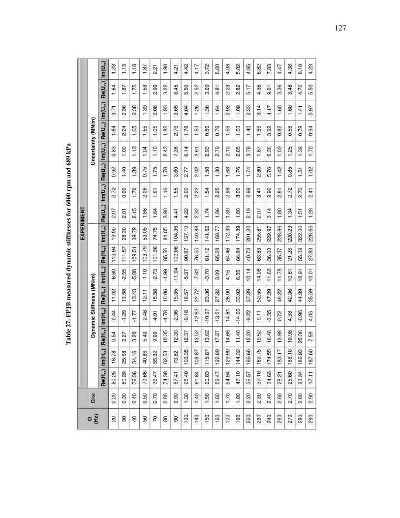
127
Ta
ble
27
. F
PJ
B m
easu
red
dy
na
mic
sti
ffn
esse
s fo
r 6
000
rp
m a
nd
68
9 k
Pa
EX
PE
RIM
EN
T
Un
cert
ain
ty (
MN
/m)
Im(U
yy)
1.2
3
1.1
3
1.1
8
1.8
7
2.2
1
1.9
8
4.2
1
4.4
2
4.1
7
3.7
2
5.6
0
4.9
8
5.8
2
4.9
5
6.8
2
7.8
3
4.4
7
4.3
8
8.1
8
4.2
3
Re(U
yy)
1.6
4
1.8
7
1.7
5
1.5
3
2.9
0
3.2
2
8.4
5
5.5
0
2.5
2
3.2
0
4.8
1
2.2
3
2.8
2
5.1
7
4.3
6
9.0
1
3.3
6
3.4
8
4.7
6
5.5
0
Im(U
yx)
3.7
1
2.3
6
2.3
8
1.3
9
2.0
8
1.9
3
3.6
5
4.0
4
1.2
6
1.3
6
1.6
4
0.9
3
1.0
9
2.3
3
3.1
4
4.1
7
1.6
0
1.6
0
1.4
1
0.9
7
Re(U
yx)
1.8
4
2.2
4
1.6
5
1.5
5
1.0
5
1.8
2
2.7
6
1.7
8
1.5
3
0.8
6
0.7
6
1.5
6
1.6
3
1.4
0
1.8
6
3.9
2
0.8
2
0.5
8
0.7
9
0.9
4
Im(U
xy)
0.8
3
1.0
0
1.1
3
1.0
4
1.1
0
2.4
3
7.3
8
6.1
4
2.6
1
2.9
3
2.7
9
2.1
0
2.8
5
3.7
8
1.6
7
6.3
6
1.0
3
1.2
5
1.3
9
1.7
0
Re(U
xy)
0.9
2
1.4
0
1.3
9
0.7
5
1.7
5
1.7
8
3.6
0
2.7
7
2.0
2
1.5
8
1.8
0
1.6
3
1.7
6
1.7
4
2.3
0
5.7
6
1.4
2
0.8
5
1.5
1
1.0
2
Im(U
xx)
2.7
2
0.9
0
1.7
0
2.0
6
1.6
1
1.1
6
1.5
5
2.0
0
2.2
2
1.5
4
2.2
5
2.9
9
3.0
0
2.9
9
3.4
1
2.9
0
2.8
1
2.7
2
2.7
0
2.4
1
Re(U
xx)
2.0
7
2.0
1
2.1
5
1.8
6
1.6
4
3.9
0
4.4
1
4.2
2
2.3
2
1.7
4
1.9
6
1.3
0
1.8
0
2.1
9
2.0
7
3.1
4
1.8
0
1.3
4
1.5
1
1.2
8
Dyn
am
ic S
tiff
ness (
MN
/m)
Im(H
yy)
19.9
0
28.3
0
39.7
9
53.0
5
74.7
5
84.0
5
104.3
6
137.1
0
140.8
8
141.6
2
169.7
7
172.3
9
174.8
9
201.2
0
255.8
1
229.9
7
228.9
6
220.2
9
322.0
6
228.6
5
Re(H
yy)
113.9
4
111.5
7
109.5
1
103.7
9
101.3
6
85.5
6
100.0
6
90.8
7
76.5
5
61.1
2
65.2
8
64.4
6
66.8
4
40.7
3
63.8
3
36.0
3
35.3
7
21.2
6
55.0
8
27.8
3
Im(H
yx)
-6.8
0
-2.5
5
-5.0
8
-1.1
0
-2.7
3
-1.9
9
-11.0
4
-5.3
7
-7.8
2
-3.7
0
3.0
9
4.1
5
6.3
5
10.1
4
14.0
8
11.6
3
11.7
8
10.6
1
18.9
1
10.0
1
Re(H
yx)
11.0
2
13.5
8
13.4
3
12.1
1
15.5
8
16.0
6
15.3
5
18.5
7
22.7
2
23.3
6
27.8
2
28.0
0
33.9
2
37.8
9
52.5
5
47.3
9
46.2
2
42.3
6
44.3
9
35.5
9
Im(H
xy)
-0.4
4
-1.2
5
-1.7
7
-2.4
8
-4.9
1
-4.7
8
-2.3
6
-9.1
8
-12.6
2
-10.9
7
-13.5
1
-14.8
1
-14.6
6
-9.2
2
-9.1
1
-3.3
5
0.7
2
4.5
8
-0.9
5
4.0
5
Re(H
xy)
0.5
4
2.2
7
3.2
0
5.4
0
9.0
0
10.3
5
12.3
0
12.3
7
13.5
2
13.6
2
17.2
7
14.6
6
11.4
0
12.2
0
19.5
2
16.4
8
13.9
8
10.9
8
25.3
6
7.5
9
Im(H
xx)
16.7
8
25.5
8
34.1
6
40.8
6
55.3
2
62.5
3
73.8
2
103.3
5
109.8
7
115.8
7
122.8
9
129.9
9
144.3
2
166.6
0
169.7
5
174.5
5
183.1
7
186.1
0
186.9
3
187.6
0
Re(H
xx)
80.2
5
80.2
9
79.3
6
79.6
6
76.4
7
74.3
8
67.4
1
65.4
0
61.8
4
60.8
3
59.4
7
54.9
4
47.1
0
39.5
7
37.1
0
34.6
3
28.2
1
25.6
0
23.3
4
17.1
1
Ω/ω
0.2
0
0.3
0
0.4
0
0.5
0
0.7
0
0.8
0
0.9
0
1.3
0
1.4
0
1.5
0
1.6
0
1.7
0
1.9
0
2.2
0
2.3
0
2.4
0
2.6
0
2.7
0
2.8
0
2.9
0
Ω
(Hz)
20
30
40
50
70
80
90
130
140
150
160
170
190
220
230
240
260
270
280
290
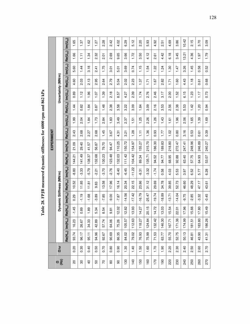
128
Ta
ble
28
. F
PJ
B m
easu
red
dy
na
mic
sti
ffn
esse
s fo
r 6
000
rp
m a
nd
86
2 k
Pa
EX
PE
RIM
EN
T
Un
cert
ain
ty (
MN
/m)
Im(U
yy)
1.6
5
1.3
7
1.6
2
1.2
7
2.2
8
2.4
2
4.0
2
6.2
9
5.1
2
2.2
0
5.9
3
4.9
2
2.5
1
4.6
9
3.8
6
10.4
2
2.1
5
3.7
0
3.0
9
Re(U
yy)
1.6
6
1.1
1
1.3
4
2.3
2
2.0
1
2.6
9
9.6
5
3.6
6
1.7
2
3.5
0
4.1
2
2.6
1
4.4
2
6.1
8
3.4
5
13.2
1
4.3
6
1.9
7
1.7
9
Im(U
yx)
5.6
0
1.4
4
3.1
8
2.4
1
1.7
5
3.0
1
5.0
1
3.6
9
0.7
4
1.1
5
1.5
4
1.2
2
1.2
4
1.3
0
1.4
7
3.2
6
1.4
5
0.5
8
0.5
2
Re(U
yx)
4.6
0
2.0
3
2.1
3
2.9
5
2.6
4
2.7
9
5.0
4
2.0
2
2.2
3
1.3
7
1.7
1
1.6
7
2.8
2
1.7
1
1.6
0
4.4
3
1.1
8
0.6
1
0.6
8
Im(U
xy)
0.8
9
1.1
2
1.9
6
1.0
7
1.3
9
2.1
8
8.5
7
4.2
7
2.3
9
1.7
4
2.7
6
2.4
6
3.1
7
2.0
0
1.5
2
6.1
5
1.2
3
1.1
7
0.7
3
Re(U
xy)
1.4
4
0.8
2
1.8
4
0.8
7
1.4
8
2.3
8
3.5
8
3.2
2
3.0
9
1.8
4
3.0
9
2.1
6
3.5
3
2.5
6
2.3
8
5.5
3
1.4
2
1.2
0
0.9
4
Im(U
xx)
1.9
9
2.0
4
1.8
4
1.7
3
2.8
4
1.8
3
3.4
9
2.3
7
1.5
1
1.2
5
2.2
6
1.2
6
1.4
3
1.6
1
1.9
6
2.0
6
1.6
5
1.3
9
1.6
9
Re(U
xx)
2.4
3
2.6
8
2.2
7
2.6
8
1.4
5
3.6
7
4.3
1
3.2
1
1.2
8
1.1
1
1.3
6
0.9
3
1.7
7
1.0
2
0.8
0
3.1
6
0.5
3
0.6
1
0.3
9
Dyn
am
ic S
tiff
ness (
MN
/m)
Im(H
yy)
21.0
9
29.4
0
41.5
7
56.8
7
79.7
0
94.4
7
110.2
5
150.7
2
154.9
7
155.2
7
215.7
0
186.3
0
189.8
3
218.8
0
272.4
7
247.4
1
248.9
6
246.8
9
240.2
7
Re(H
yy)
144.2
1
141.4
9
138.3
7
132.6
8
130.2
3
123.4
8
132.0
3
111.4
2
104.4
2
89.3
4
135.7
1
94.5
2
94.7
7
68.9
5
92.8
8
63.4
0
57.7
5
64.9
3
53.0
7
Im(H
yx)
-8.8
0
-3.3
3
-5.7
9
-2.2
1
-3.7
0
-2.7
6
-8.4
0
-6.4
5
-11.2
2
-8.3
1
-3.3
2
-1.7
4
0.5
8
4.0
3
5.5
3
3.9
7
6.5
2
5.7
7
6.2
8
Re(H
yx)
10.5
2
11.8
5
11.8
1
9.8
3
13.5
8
17.9
6
16.1
4
20.3
4
22.1
5
23.8
6
31.1
2
29.6
9
34.7
8
39.8
5
52.7
3
46.6
0
48.2
9
47.1
7
43.6
1
Im(H
xy)
0.2
9
-1.1
9
-1.6
8
-3.8
9
-7.8
5
-9.0
0
-7.8
7
-14.5
6
-17.4
2
-16.7
9
-25.4
7
-19.7
4
-18.8
9
-13.7
1
-14.0
4
-9.7
5
-2.8
5
-3.3
2
-0.4
5
Re(H
xy)
-1.4
5
0.8
9
1.8
9
5.3
4
8.5
4
9.8
1
12.0
2
12.8
2
13.9
3
14.2
7
20.1
5
14.7
2
13.0
3
15.5
4
22.0
1
17.9
6
15.6
6
17.8
0
15.4
9
Im(H
xx)
16.2
3
26.6
7
34.3
3
42.8
9
57.7
4
64.0
6
75.2
6
105.5
7
112.6
3
118.2
7
124.8
4
132.4
2
146.3
0
167.7
1
171.3
6
174.9
9
181.5
1
183.8
0
186.2
6
Re(H
xx)
93.7
4
96.1
7
95.1
1
94.9
6
92.6
7
90.6
9
86.3
5
84.0
2
79.0
2
76.9
3
75.9
9
71.5
3
63.7
7
55.7
0
52.7
5
50.1
3
46.8
1
43.9
0
41.3
1
Ω/ω
0.2
0
0.3
0
0.4
0
0.5
0
0.7
0
0.8
0
0.9
0
1.3
0
1.4
0
1.5
0
1.6
0
1.7
0
1.9
0
2.2
0
2.3
0
2.4
0
2.5
0
2.6
0
2.7
0
Ω
(Hz)
20
30
40
50
70
80
90
130
140
150
160
170
190
220
230
240
250
260
270
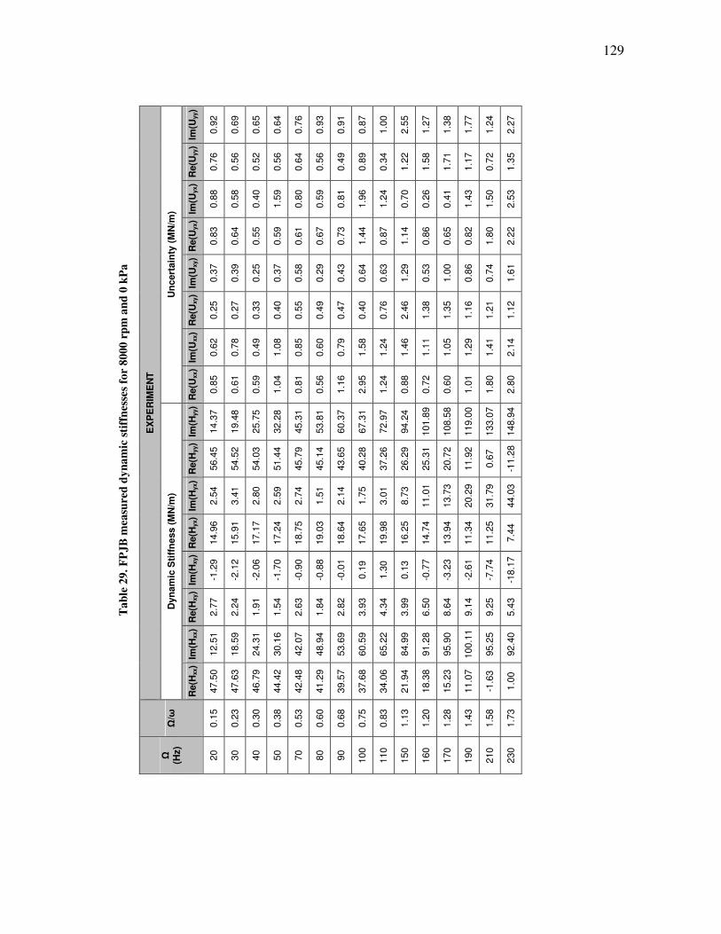
129
Ta
ble
29
. F
PJ
B m
easu
red
dy
na
mic
sti
ffn
esse
s fo
r 8
000
rp
m a
nd
0 k
Pa
EX
PE
RIM
EN
T
Un
cert
ain
ty (
MN
/m)
Im(U
yy)
0.9
2
0.6
9
0.6
5
0.6
4
0.7
6
0.9
3
0.9
1
0.8
7
1.0
0
2.5
5
1.2
7
1.3
8
1.7
7
1.2
4
2.2
7
Re(U
yy)
0.7
6
0.5
6
0.5
2
0.5
6
0.6
4
0.5
6
0.4
9
0.8
9
0.3
4
1.2
2
1.5
8
1.7
1
1.1
7
0.7
2
1.3
5
Im(U
yx)
0.8
8
0.5
8
0.4
0
1.5
9
0.8
0
0.5
9
0.8
1
1.9
6
1.2
4
0.7
0
0.2
6
0.4
1
1.4
3
1.5
0
2.5
3
Re(U
yx)
0.8
3
0.6
4
0.5
5
0.5
9
0.6
1
0.6
7
0.7
3
1.4
4
0.8
7
1.1
4
0.8
6
0.6
5
0.8
2
1.8
0
2.2
2
Im(U
xy)
0.3
7
0.3
9
0.2
5
0.3
7
0.5
8
0.2
9
0.4
3
0.6
4
0.6
3
1.2
9
0.5
3
1.0
0
0.8
6
0.7
4
1.6
1
Re(U
xy)
0.2
5
0.2
7
0.3
3
0.4
0
0.5
5
0.4
9
0.4
7
0.4
0
0.7
6
2.4
6
1.3
8
1.3
5
1.1
6
1.2
1
1.1
2
Im(U
xx)
0.6
2
0.7
8
0.4
9
1.0
8
0.8
5
0.6
0
0.7
9
1.5
8
1.2
4
1.4
6
1.1
1
1.0
5
1.2
9
1.4
1
2.1
4
Re(U
xx)
0.8
5
0.6
1
0.5
9
1.0
4
0.8
1
0.5
6
1.1
6
2.9
5
1.2
4
0.8
8
0.7
2
0.6
0
1.0
1
1.8
0
2.8
0
Dyn
am
ic S
tiff
ness (
MN
/m)
Im(H
yy)
14.3
7
19.4
8
25.7
5
32.2
8
45.3
1
53.8
1
60.3
7
67.3
1
72.9
7
94.2
4
101.8
9
108.5
8
119.0
0
133.0
7
148.9
4
Re(H
yy)
56.4
5
54.5
2
54.0
3
51.4
4
45.7
9
45.1
4
43.6
5
40.2
8
37.2
6
26.2
9
25.3
1
20.7
2
11.9
2
0.6
7
-11.2
8
Im(H
yx)
2.5
4
3.4
1
2.8
0
2.5
9
2.7
4
1.5
1
2.1
4
1.7
5
3.0
1
8.7
3
11.0
1
13.7
3
20.2
9
31.7
9
44.0
3
Re(H
yx)
14.9
6
15.9
1
17.1
7
17.2
4
18.7
5
19.0
3
18.6
4
17.6
5
19.9
8
16.2
5
14.7
4
13.9
4
11.3
4
11.2
5
7.4
4
Im(H
xy)
-1.2
9
-2.1
2
-2.0
6
-1.7
0
-0.9
0
-0.8
8
-0.0
1
0.1
9
1.3
0
0.1
3
-0.7
7
-3.2
3
-2.6
1
-7.7
4
-18.1
7
Re(H
xy)
2.7
7
2.2
4
1.9
1
1.5
4
2.6
3
1.8
4
2.8
2
3.9
3
4.3
4
3.9
9
6.5
0
8.6
4
9.1
4
9.2
5
5.4
3
Im(H
xx)
12.5
1
18.5
9
24.3
1
30.1
6
42.0
7
48.9
4
53.6
9
60.5
9
65.2
2
84.9
9
91.2
8
95.9
0
100.1
1
95.2
5
92.4
0
Re(H
xx)
47.5
0
47.6
3
46.7
9
44.4
2
42.4
8
41.2
9
39.5
7
37.6
8
34.0
6
21.9
4
18.3
8
15.2
3
11.0
7
-1.6
3
1.0
0
Ω/ω
0.1
5
0.2
3
0.3
0
0.3
8
0.5
3
0.6
0
0.6
8
0.7
5
0.8
3
1.1
3
1.2
0
1.2
8
1.4
3
1.5
8
1.7
3
Ω
(Hz)
20
30
40
50
70
80
90
100
110
150
160
170
190
210
230

130
Ta
ble
30
. F
PJ
B m
easu
red
dy
na
mic
sti
ffn
esse
s fo
r 8
000
rp
m a
nd
17
2 k
Pa
EX
PE
RIM
EN
T
Un
cert
ain
ty (
MN
/m)
Im(U
yy)
0.8
8
0.4
1
0.5
8
0.4
3
0.6
5
3.1
9
0.6
8
0.7
9
0.6
5
2.8
3
1.6
6
1.5
2
1.5
2
2.0
9
2.9
6
1.9
6
0.8
2
Re(U
yy)
0.8
8
0.8
1
0.9
0
0.7
0
0.9
9
5.0
0
0.5
7
0.5
2
0.3
4
1.3
9
2.0
0
1.0
4
1.2
7
1.7
3
3.9
5
2.0
0
2.0
2
Im(U
yx)
0.9
1
0.5
6
0.2
3
1.1
1
0.4
2
0.6
5
0.2
1
1.5
1
1.1
4
1.2
8
0.4
2
0.4
8
0.8
4
1.1
3
0.9
0
1.5
9
1.8
0
Re(U
yx)
0.8
1
0.5
0
0.2
6
1.3
8
0.3
3
0.8
7
0.8
7
0.8
5
0.9
9
0.4
7
0.8
1
0.6
0
0.9
4
1.4
4
1.1
1
0.8
4
2.2
9
Im(U
xy)
0.3
0
0.2
9
0.1
9
0.3
6
0.3
5
0.5
2
0.4
4
0.6
3
0.6
8
0.5
6
1.5
2
0.6
7
0.5
4
0.7
2
0.4
4
0.7
1
0.6
2
Re(U
xy)
0.3
2
0.2
4
0.4
8
0.3
5
0.5
5
0.6
6
0.5
3
0.6
6
1.2
4
3.5
5
1.5
8
1.3
7
0.9
6
0.8
1
0.5
2
0.8
1
1.6
9
Im(U
xx)
0.6
9
0.5
9
0.3
2
1.5
5
0.6
1
0.4
8
0.7
5
0.9
8
0.9
8
1.1
8
1.0
6
0.4
4
0.9
7
1.7
0
1.2
8
1.0
4
2.7
4
Re(U
xx)
0.8
4
0.7
2
0.5
7
0.9
6
0.6
5
0.6
6
0.7
4
1.7
2
0.9
6
0.8
6
0.8
7
0.8
5
1.0
8
2.4
2
1.0
3
0.8
7
3.5
4
Dyn
am
ic S
tiff
ness (
MN
/m)
Im(H
yy)
12.6
5
17.1
2
23.5
4
29.6
0
40.6
0
64.8
6
55.9
0
62.9
8
66.4
3
84.4
1
106.9
7
102.2
4
102.4
3
108.0
6
112.2
0
138.8
5
132.8
6
Re(H
yy)
57.2
5
55.9
5
54.1
7
50.9
4
44.5
9
60.9
1
46.0
0
41.1
9
37.1
7
10.4
4
33.5
4
19.7
4
9.1
2
0.6
7
-19.2
8
-2.4
8
-27.9
2
Im(H
yx)
0.6
5
1.5
3
1.5
4
1.2
9
2.3
6
5.1
6
1.9
3
5.1
8
5.2
7
6.1
2
11.4
1
11.9
9
16.4
5
17.5
5
22.3
1
27.1
6
26.4
1
Re(H
yx)
14.8
9
14.3
7
15.1
6
14.9
9
15.8
3
19.1
5
15.9
7
13.5
4
18.8
5
14.3
9
16.4
7
15.9
8
16.5
5
9.8
8
16.7
0
15.7
3
11.5
0
Im(H
xy)
-1.0
2
-1.4
8
-1.1
5
-1.2
7
-0.7
6
-2.1
2
-0.5
5
-0.1
0
-0.3
2
-0.5
6
-0.9
7
-1.4
7
-1.4
2
-2.9
0
0.2
5
-1.5
6
-8.3
7
Re(H
xy)
0.8
7
0.7
4
0.3
7
0.7
6
1.2
4
2.4
5
1.6
6
2.7
5
2.8
1
2.7
0
6.6
1
6.3
0
6.1
2
9.5
6
7.2
7
7.3
4
5.6
2
Im(H
xx)
11.9
3
16.4
4
21.6
8
26.7
5
36.6
7
42.3
7
46.8
1
53.7
3
59.5
8
77.5
3
82.7
6
87.2
9
88.4
7
110.4
1
92.7
4
96.7
2
96.6
9
Re(H
xx)
47.1
3
47.3
6
46.3
3
45.4
6
42.1
3
40.1
7
37.9
9
35.6
0
32.9
4
21.2
7
17.9
2
15.1
2
9.7
2
-15.1
9
-7.4
5
-16.0
1
-41.4
4
Ω/ω
0.1
5
0.2
3
0.3
0
0.3
8
0.5
3
0.6
0
0.6
8
0.7
5
0.8
3
1.1
3
1.2
0
1.2
8
1.4
3
1.5
0
1.5
8
1.7
3
1.8
8
Ω
(Hz)
20
30
40
50
70
80
90
100
110
150
160
170
190
200
210
230
250

131
Ta
ble
31
. F
PJ
B m
easu
red
dy
na
mic
sti
ffn
esse
s fo
r 8
000
rp
m a
nd
34
5 k
Pa
EX
PE
RIM
EN
T
Un
cert
ain
ty (
MN
/m)
Im(U
yy)
1.1
4
1.8
8
2.5
1
3.2
4
5.1
3
3.6
9
6.7
5
7.1
6
7.5
0
7.0
8
9.1
2
8.7
9
10.6
3
9.4
6
8.7
1
13.0
9
8.8
1
18.2
5
Re(U
yy)
1.2
3
0.9
1
1.1
3
1.0
9
1.1
6
2.1
9
1.6
7
1.9
3
2.2
2
2.5
2
2.6
1
2.0
8
1.9
2
1.1
9
1.2
7
1.2
5
4.0
3
4.0
2
Im(U
yx)
1.0
6
0.8
9
0.4
8
1.1
8
0.8
3
1.0
6
0.5
4
1.9
5
1.9
7
1.1
4
0.7
1
1.3
7
2.7
7
2.3
4
2.6
5
3.4
3
3.7
5
6.9
6
Re(U
yx)
0.7
5
0.8
9
0.4
7
0.9
3
0.6
7
0.6
7
1.4
4
1.2
7
0.8
7
1.3
5
1.0
6
1.5
6
2.1
3
1.8
1
1.4
3
2.2
1
3.1
7
3.3
2
Im(U
xy)
0.3
7
0.3
6
0.4
9
0.5
3
0.5
7
0.5
9
1.1
1
1.0
6
1.4
8
2.5
2
1.1
3
1.5
2
1.5
7
1.1
7
1.3
4
1.8
0
3.6
2
2.9
9
Re(U
xy)
0.2
5
0.3
6
0.5
3
0.6
2
0.6
1
0.9
7
1.1
5
1.5
4
2.0
3
3.6
3
2.9
8
2.0
5
2.9
1
2.2
9
1.8
2
2.3
9
1.3
8
2.0
2
Im(U
xx)
0.9
8
1.8
3
2.4
1
2.7
6
3.7
1
3.6
6
5.1
5
6.0
0
6.2
2
6.7
2
7.1
1
6.2
6
8.8
5
8.0
3
9.5
5
9.7
3
12.4
1
8.0
9
Re(U
xx)
1.1
8
1.2
2
1.1
2
1.2
6
1.1
9
1.2
4
2.1
2
2.6
0
3.2
5
1.5
9
1.6
0
1.4
8
2.1
2
2.2
5
1.6
8
0.9
7
2.4
9
2.4
5
Dyn
am
ic S
tiff
ness (
MN
/m)
Im(H
yy)
14.6
6
19.0
7
25.5
1
32.9
8
45.6
7
70.4
9
60.5
2
69.6
6
72.3
5
123.1
6
109.3
4
108.2
9
115.6
0
121.1
6
119.8
6
150.3
3
139.8
8
153.2
4
Re(H
yy)
65.3
0
64.6
3
62.3
5
59.2
7
53.2
9
19.3
7
58.6
7
49.8
8
45.6
4
53.8
7
27.0
2
22.4
1
17.2
2
1.4
6
-16.0
7
12.1
0
-27.4
1
-46.3
8
Im(H
yx)
-1.4
2
0.4
8
0.4
2
1.1
5
2.3
6
4.8
0
0.7
2
8.3
6
5.6
1
11.7
2
12.0
3
15.5
9
18.1
2
23.5
3
15.3
2
25.6
5
32.2
1
17.3
0
Re(H
yx)
16.1
2
14.9
5
15.7
0
15.2
2
16.2
7
13.6
4
14.5
5
10.2
9
20.7
4
20.8
7
18.5
2
19.9
6
12.6
4
20.4
3
10.2
2
23.7
7
25.2
4
27.0
9
Im(H
xy)
-0.5
8
-0.9
8
-0.7
4
-0.4
3
-0.2
3
0.2
2
-1.0
0
-0.2
4
-0.6
9
-2.0
4
-1.5
9
-2.4
4
-2.9
4
0.0
5
0.0
2
-1.7
1
0.7
6
0.0
2
Re(H
xy)
0.1
9
0.7
0
0.2
8
0.9
0
2.3
6
4.2
1
3.6
3
4.1
5
4.4
5
9.8
1
8.6
2
8.2
8
12.3
4
8.4
2
7.2
4
11.5
5
7.9
2
5.8
0
Im(H
xx)
12.7
5
17.8
4
22.9
0
28.2
7
38.7
9
44.1
4
49.1
4
57.5
5
61.2
8
85.3
0
90.2
5
89.6
1
119.0
6
96.4
5
105.5
1
103.5
1
111.4
6
110.2
4
Re(H
xx)
51.4
8
51.9
5
51.0
7
49.9
3
47.2
7
45.5
0
42.8
5
41.9
7
38.2
3
24.8
8
21.6
5
15.4
6
-6.1
2
-3.5
2
-12.8
7
-13.9
2
-40.9
7
-6.0
2
Ω/ω
0.1
5
0.2
3
0.3
0
0.3
8
0.5
3
0.6
0
0.6
8
0.7
5
0.8
3
1.2
0
1.2
8
1.4
3
1.5
0
1.5
8
1.6
5
1.7
3
1.8
8
2.0
3
Ω
(Hz)
20
30
40
50
70
80
90
100
110
160
170
190
200
210
220
230
250
270
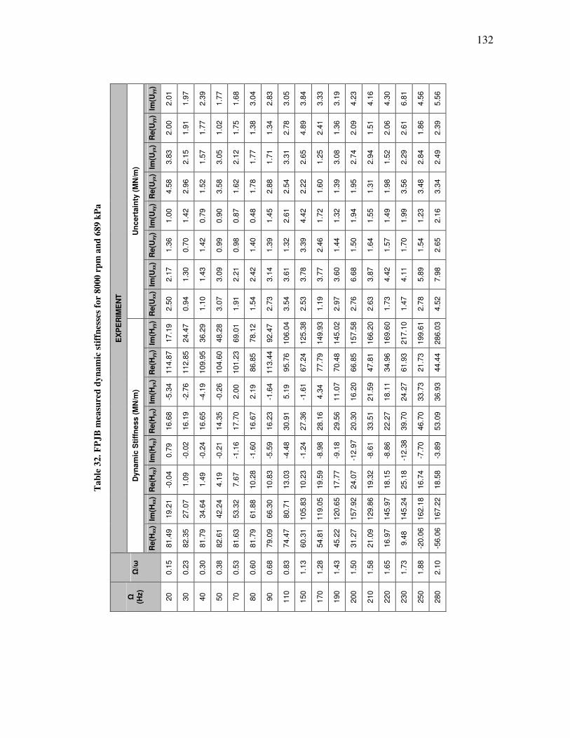
132
Ta
ble
32
. F
PJ
B m
easu
red
dy
na
mic
sti
ffn
esse
s fo
r 8
000
rp
m a
nd
68
9 k
Pa
EX
PE
RIM
EN
T
Un
cert
ain
ty (
MN
/m)
Im(U
yy)
2.0
1
1.9
7
2.3
9
1.7
7
1.6
8
3.0
4
2.8
3
3.0
5
3.8
4
3.3
3
3.1
9
4.2
3
4.1
6
4.3
0
6.8
1
4.5
6
5.5
6
Re(U
yy)
2.0
0
1.9
1
1.7
7
1.0
2
1.7
5
1.3
8
1.3
4
2.7
8
4.8
9
2.4
1
1.3
6
2.0
9
1.5
1
2.0
6
2.6
1
1.8
6
2.3
9
Im(U
yx)
3.8
3
2.1
5
1.5
7
3.0
5
2.1
2
1.7
7
1.7
1
3.3
1
2.6
5
1.2
5
3.0
8
2.7
4
2.9
4
1.5
2
2.2
9
2.8
4
2.4
9
Re(U
yx)
4.5
8
2.9
6
1.5
2
3.5
8
1.6
2
1.7
8
2.8
8
2.5
4
2.2
2
1.6
0
1.3
9
1.9
5
1.3
1
1.9
8
3.5
6
3.4
8
3.3
4
Im(U
xy)
1.0
0
1.4
2
0.7
9
0.9
0
0.8
7
0.4
8
1.4
5
2.6
1
4.4
2
1.7
2
1.3
2
1.9
4
1.5
5
1.4
9
1.9
9
1.2
3
2.1
6
Re(U
xy)
1.3
6
0.7
0
1.4
2
0.9
9
0.9
8
1.4
0
1.3
9
1.3
2
3.3
9
2.4
6
1.4
4
1.5
0
1.6
4
1.5
7
1.7
0
1.5
4
2.6
5
Im(U
xx)
2.1
7
1.3
0
1.4
3
3.0
9
2.2
1
2.4
2
3.1
4
3.6
1
3.7
8
3.7
7
3.6
0
6.6
8
3.8
7
4.4
2
4.1
1
5.8
9
7.9
8
Re(U
xx)
2.5
0
0.9
4
1.1
0
3.0
7
1.9
1
1.5
4
2.7
3
3.5
4
2.5
3
1.1
9
2.9
7
2.7
6
2.6
3
1.7
3
1.4
7
2.7
8
4.5
2
Dyn
am
ic S
tiff
ness (
MN
/m)
Im(H
yy)
17.1
9
24.4
7
36.2
9
48.2
8
69.0
1
78.1
2
92.4
7
106.0
4
125.3
8
149.9
3
145.0
2
157.5
8
166.2
0
169.6
0
217.1
0
199.6
1
286.0
3
Re(H
yy)
114.8
7
112.8
5
109.9
5
104.6
0
101.2
3
86.8
5
113.4
4
95.7
6
67.2
4
77.7
9
70.4
8
66.8
5
47.8
1
34.9
6
61.9
3
21.7
3
44.4
4
Im(H
yx)
-5.3
4
-2.7
6
-4.1
9
-0.2
6
2.0
0
2.1
9
-1.6
4
5.1
9
-1.6
1
4.3
4
11.0
7
16.2
0
21.5
9
18.1
1
24.2
7
33.7
3
36.9
3
Re(H
yx)
16.6
8
16.1
9
16.6
5
14.3
5
17.7
0
16.6
7
16.2
3
30.9
1
27.3
6
28.1
6
29.5
6
20.3
0
33.5
1
22.2
7
39.7
0
46.7
0
53.0
9
Im(H
xy)
0.7
9
-0.0
2
-0.2
4
-0.2
1
-1.1
6
-1.6
0
-5.5
9
-4.4
8
-1.2
4
-8.9
8
-9.1
8
-12.9
7
-8.6
1
-8.8
6
-12.3
8
-7.7
0
-3.8
9
Re(H
xy)
-0.0
4
1.0
9
1.4
9
4.1
9
7.6
7
10.2
8
10.8
3
13.0
3
10.2
3
19.5
9
17.7
7
24.0
7
19.3
2
18.1
5
25.1
8
16.7
4
18.5
8
Im(H
xx)
19.2
1
27.0
7
34.6
4
42.2
4
53.3
2
61.8
8
66.3
0
80.7
1
105.8
3
119.0
5
120.6
5
157.9
2
129.8
6
145.9
7
145.2
4
162.1
8
167.2
2
Re(H
xx)
81.4
9
82.3
5
81.7
9
82.6
1
81.6
3
81.7
9
79.0
9
74.4
7
60.3
1
54.8
1
45.2
2
31.2
7
21.0
9
16.9
7
9.4
8
-20.0
6
-56.0
6
Ω/ω
0.1
5
0.2
3
0.3
0
0.3
8
0.5
3
0.6
0
0.6
8
0.8
3
1.1
3
1.2
8
1.4
3
1.5
0
1.5
8
1.6
5
1.7
3
1.8
8
2.1
0
Ω
(Hz)
20
30
40
50
70
80
90
110
150
170
190
200
210
220
230
250
280
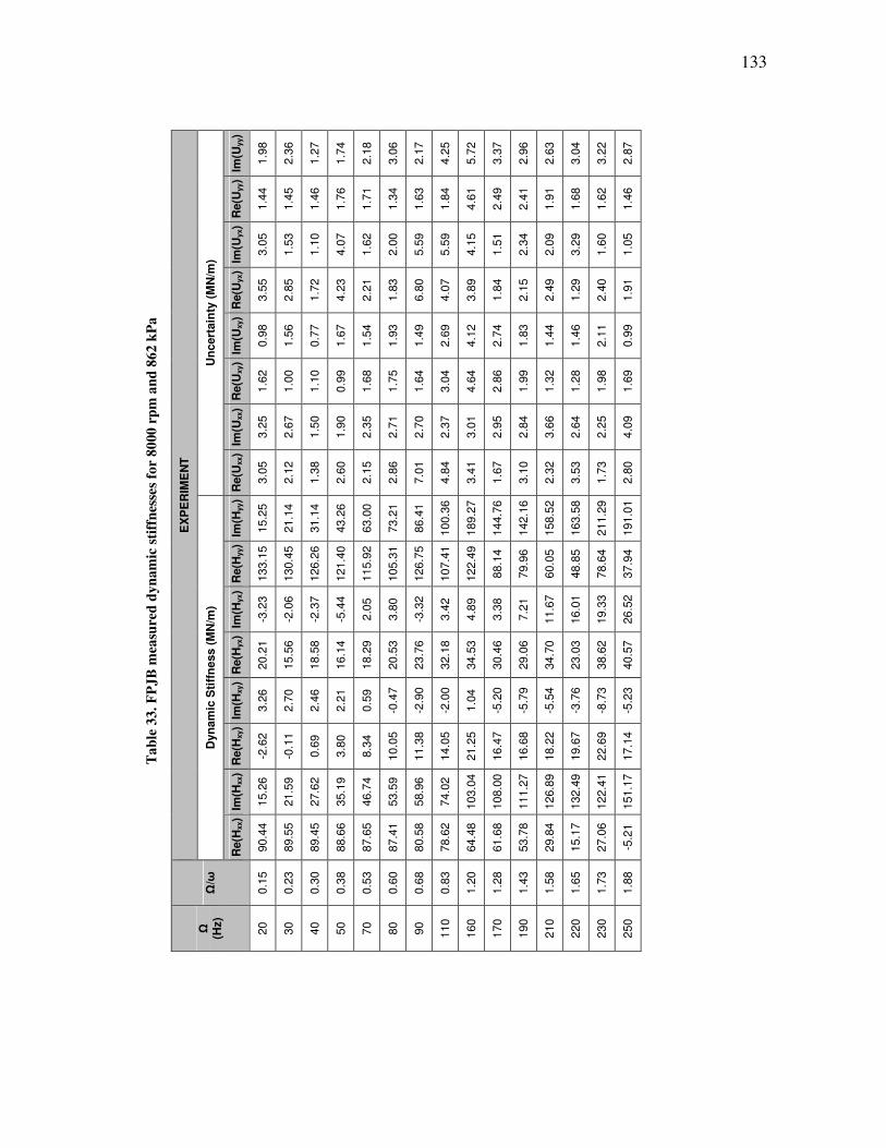
133
Ta
ble
33
. F
PJ
B m
easu
red
dy
na
mic
sti
ffn
esse
s fo
r 8
000
rp
m a
nd
86
2 k
Pa
EX
PE
RIM
EN
T
Un
cert
ain
ty (
MN
/m)
Im(U
yy)
1.9
8
2.3
6
1.2
7
1.7
4
2.1
8
3.0
6
2.1
7
4.2
5
5.7
2
3.3
7
2.9
6
2.6
3
3.0
4
3.2
2
2.8
7
Re(U
yy)
1.4
4
1.4
5
1.4
6
1.7
6
1.7
1
1.3
4
1.6
3
1.8
4
4.6
1
2.4
9
2.4
1
1.9
1
1.6
8
1.6
2
1.4
6
Im(U
yx)
3.0
5
1.5
3
1.1
0
4.0
7
1.6
2
2.0
0
5.5
9
5.5
9
4.1
5
1.5
1
2.3
4
2.0
9
3.2
9
1.6
0
1.0
5
Re(U
yx)
3.5
5
2.8
5
1.7
2
4.2
3
2.2
1
1.8
3
6.8
0
4.0
7
3.8
9
1.8
4
2.1
5
2.4
9
1.2
9
2.4
0
1.9
1
Im(U
xy)
0.9
8
1.5
6
0.7
7
1.6
7
1.5
4
1.9
3
1.4
9
2.6
9
4.1
2
2.7
4
1.8
3
1.4
4
1.4
6
2.1
1
0.9
9
Re(U
xy)
1.6
2
1.0
0
1.1
0
0.9
9
1.6
8
1.7
5
1.6
4
3.0
4
4.6
4
2.8
6
1.9
9
1.3
2
1.2
8
1.9
8
1.6
9
Im(U
xx)
3.2
5
2.6
7
1.5
0
1.9
0
2.3
5
2.7
1
2.7
0
2.3
7
3.0
1
2.9
5
2.8
4
3.6
6
2.6
4
2.2
5
4.0
9
Re(U
xx)
3.0
5
2.1
2
1.3
8
2.6
0
2.1
5
2.8
6
7.0
1
4.8
4
3.4
1
1.6
7
3.1
0
2.3
2
3.5
3
1.7
3
2.8
0
Dyn
am
ic S
tiff
ness (
MN
/m)
Im(H
yy)
15.2
5
21.1
4
31.1
4
43.2
6
63.0
0
73.2
1
86.4
1
100.3
6
189.2
7
144.7
6
142.1
6
158.5
2
163.5
8
211.2
9
191.0
1
Re(H
yy)
133.1
5
130.4
5
126.2
6
121.4
0
115.9
2
105.3
1
126.7
5
107.4
1
122.4
9
88.1
4
79.9
6
60.0
5
48.8
5
78.6
4
37.9
4
Im(H
yx)
-3.2
3
-2.0
6
-2.3
7
-5.4
4
2.0
5
3.8
0
-3.3
2
3.4
2
4.8
9
3.3
8
7.2
1
11.6
7
16.0
1
19.3
3
26.5
2
Re(H
yx)
20.2
1
15.5
6
18.5
8
16.1
4
18.2
9
20.5
3
23.7
6
32.1
8
34.5
3
30.4
6
29.0
6
34.7
0
23.0
3
38.6
2
40.5
7
Im(H
xy)
3.2
6
2.7
0
2.4
6
2.2
1
0.5
9
-0.4
7
-2.9
0
-2.0
0
1.0
4
-5.2
0
-5.7
9
-5.5
4
-3.7
6
-8.7
3
-5.2
3
Re(H
xy)
-2.6
2
-0.1
1
0.6
9
3.8
0
8.3
4
10.0
5
11.3
8
14.0
5
21.2
5
16.4
7
16.6
8
18.2
2
19.6
7
22.6
9
17.1
4
Im(H
xx)
15.2
6
21.5
9
27.6
2
35.1
9
46.7
4
53.5
9
58.9
6
74.0
2
103.0
4
108.0
0
111.2
7
126.8
9
132.4
9
122.4
1
151.1
7
Re(H
xx)
90.4
4
89.5
5
89.4
5
88.6
6
87.6
5
87.4
1
80.5
8
78.6
2
64.4
8
61.6
8
53.7
8
29.8
4
15.1
7
27.0
6
-5.2
1
Ω/ω
0.1
5
0.2
3
0.3
0
0.3
8
0.5
3
0.6
0
0.6
8
0.8
3
1.2
0
1.2
8
1.4
3
1.5
8
1.6
5
1.7
3
1.8
8
Ω
(Hz)
20
30
40
50
70
80
90
110
160
170
190
210
220
230
250

134
Ta
ble
34
. F
PJ
B m
easu
red
dy
na
mic
sti
ffn
esse
s fo
r 1
000
0 r
pm
an
d 0
kP
a
EX
PE
RIM
EN
T
Un
cert
ain
ty (
MN
/m)
Im(U
yy)
1.1
2
0.6
3
0.7
3
0.9
2
2.0
7
1.4
6
0.8
5
1.1
6
1.1
4
1.4
4
1.4
5
2.4
2
4.5
3
Re(U
yy)
1.1
0
0.6
7
0.7
0
1.1
2
2.5
5
1.2
3
1.0
5
1.6
1
0.9
8
1.4
7
1.5
8
1.6
4
3.3
6
Im(U
yx)
1.3
6
1.0
7
0.8
3
2.2
0
1.9
0
1.2
8
3.2
8
1.6
5
3.5
4
4.2
9
1.4
5
2.3
7
3.0
5
Re(U
yx)
1.6
2
1.4
4
0.8
7
3.2
0
1.0
7
1.4
3
3.9
5
4.1
3
1.4
3
2.8
0
1.9
8
1.7
8
3.0
0
Im(U
xy)
0.4
4
0.4
3
0.7
3
1.0
1
0.7
0
0.9
1
1.0
1
0.9
7
0.9
1
1.8
8
1.5
1
2.2
1
3.6
2
Re(U
xy)
0.4
9
0.5
9
0.5
2
0.4
3
0.5
9
1.0
7
0.8
1
1.1
1
0.9
1
1.1
4
1.1
2
1.9
8
1.9
4
Im(U
xx)
1.5
6
1.5
2
0.8
1
2.7
6
1.6
6
1.0
5
4.4
1
4.5
4
3.0
2
2.9
0
2.1
2
1.5
9
3.7
2
Re(U
xx)
1.1
9
1.0
9
0.7
0
1.7
0
1.9
0
1.6
5
2.6
9
3.6
1
2.3
4
4.3
9
2.2
2
2.3
0
2.0
2
Dyn
am
ic S
tiff
ness (
MN
/m)
Im(H
yy)
14.1
3
19.4
6
26.1
0
31.5
2
50.2
5
52.6
3
57.3
8
63.8
3
69.7
5
82.9
5
85.0
9
103.0
6
128.8
6
Re(H
yy)
66.5
9
64.7
0
64.3
5
62.0
9
51.7
9
60.2
2
56.0
8
50.1
8
46.2
7
43.6
0
37.8
4
19.7
4
1.6
2
Im(H
yx)
2.2
8
3.2
2
3.1
8
4.5
4
3.6
8
2.2
2
1.5
7
0.8
1
1.7
7
1.7
0
3.1
8
10.5
6
16.1
2
Re(H
yx)
15.1
0
16.0
1
17.4
8
17.4
5
19.0
8
21.8
0
20.5
1
18.2
7
20.0
6
16.1
7
18.3
5
11.4
3
1.1
2
Im(H
xy)
-1.4
4
-2.4
7
-2.5
6
-2.6
4
-2.5
8
-3.0
5
-1.0
8
-0.5
1
0.9
2
4.1
2
2.5
7
-1.2
3
-5.9
4
Re(H
xy)
0.3
9
0.0
3
-0.1
6
-1.0
1
-0.5
3
-2.4
6
-2.4
7
-1.7
3
-0.5
5
-0.3
1
-2.1
6
-1.4
7
6.7
0
Im(H
xx)
13.2
4
17.8
1
23.5
8
29.3
5
39.3
5
44.4
1
54.0
7
58.0
2
65.3
0
74.7
1
78.8
5
91.9
5
93.3
0
Re(H
xx)
56.1
8
55.7
0
55.7
4
54.3
1
51.5
6
50.3
6
45.5
1
48.0
7
41.1
8
42.9
8
32.5
8
19.0
4
-3.9
7
Ω/ω
0.1
2
0.1
8
0.2
4
0.3
0
0.4
2
0.4
8
0.5
4
0.6
0
0.6
6
0.7
8
0.8
4
1.1
4
1.2
6
Ω
(Hz)
20
30
40
50
70
80
90
100
110
130
140
190
210

135
Ta
ble
35
. F
PJ
B m
easu
red
dy
na
mic
sti
ffn
esse
s fo
r 1
000
0 r
pm
an
d 1
72
kP
a
EX
PE
RIM
EN
T
Un
cert
ain
ty (
MN
/m)
Im(U
yy)
1.1
2
0.7
4
0.7
2
0.7
9
0.8
3
0.7
1
0.7
3
1.7
6
1.2
2
2.1
9
3.6
5
5.7
6
4.4
4
2.9
8
2.6
4
1.5
3
2.9
2
1.5
4
Re(U
yy)
1.2
9
1.2
1
0.6
1
1.1
1
0.9
0
1.8
4
0.9
0
1.4
3
1.4
9
1.8
9
2.5
3
1.7
9
1.8
3
2.3
8
1.7
3
1.1
9
2.4
5
1.4
2
Im(U
yx)
1.2
7
1.0
3
0.7
9
2.5
5
1.4
9
1.1
6
2.2
4
2.9
8
1.4
8
1.9
4
1.6
4
3.2
0
4.1
0
1.9
9
1.9
7
1.2
0
3.1
2
2.2
4
Re(U
yx)
1.9
4
1.5
3
1.1
1
1.8
0
1.5
7
1.2
4
4.4
6
3.2
5
3.3
9
2.4
8
1.9
2
2.1
9
6.7
0
1.3
5
1.7
2
0.7
5
1.6
7
1.9
2
Im(U
xy)
0.5
2
0.5
2
0.5
2
0.7
5
0.6
4
0.8
2
0.6
1
1.0
6
0.8
1
1.3
9
1.8
3
1.3
9
2.3
8
2.0
6
1.0
8
1.3
5
1.0
4
2.1
3
Re(U
xy)
0.4
9
0.6
5
0.5
7
0.4
9
0.9
2
0.7
1
0.9
7
0.8
2
0.7
9
1.7
1
3.0
7
4.9
5
4.3
7
2.2
2
1.1
5
1.4
9
1.9
9
1.3
7
Im(U
xx)
1.2
2
1.5
3
1.0
2
1.7
3
1.9
1
1.8
2
3.1
8
2.6
2
2.1
6
2.6
7
1.7
6
2.3
1
3.3
2
1.7
0
1.5
3
2.4
8
4.8
6
4.0
4
Re(U
xx)
1.7
6
1.1
3
0.6
5
1.8
2
1.2
3
1.8
3
2.4
9
2.7
7
1.7
6
3.1
9
1.9
1
3.5
3
6.0
7
2.6
3
1.3
6
2.7
4
5.5
9
3.4
3
Dyn
am
ic S
tiff
ness (
MN
/m)
Im(H
yy)
13.5
4
18.2
0
24.4
1
30.5
0
40.3
1
63.3
9
55.1
3
61.2
9
66.0
7
79.2
5
82.4
5
98.8
1
104.8
7
108.4
3
135.2
3
132.5
5
127.7
6
157.4
3
Re(H
yy)
70.2
4
68.7
9
68.0
1
65.2
2
58.8
6
75.3
6
59.9
9
53.6
0
49.8
6
43.1
5
35.3
9
20.6
8
14.4
7
-4.2
4
15.1
3
-12.8
0
-32.0
0
-21.4
6
Im(H
yx)
1.7
4
2.6
2
2.3
9
2.2
4
2.1
9
4.6
7
3.0
2
2.6
9
2.4
8
-0.1
7
1.6
5
9.8
3
12.2
7
12.4
4
21.7
0
21.0
1
18.3
3
37.2
7
Re(H
yx)
15.4
4
15.8
2
16.6
4
16.6
0
19.2
9
22.5
7
17.8
1
21.0
4
21.6
5
20.6
1
20.4
3
15.3
6
13.9
6
15.7
2
15.9
0
12.1
1
7.0
1
0.4
7
Im(H
xy)
-1.5
5
-2.2
7
-2.1
8
-2.2
3
-1.4
5
-3.2
4
-0.8
0
0.0
7
1.0
1
2.6
6
3.1
7
2.4
9
-3.1
4
0.9
1
-0.7
5
-12.4
0
-28.5
0
-33.8
7
Re(H
xy)
-1.5
9
-2.2
7
-2.5
1
-2.5
7
-2.3
5
-1.0
7
-2.7
7
-2.0
3
-0.9
1
2.0
8
1.5
0
2.4
1
10.0
1
8.8
4
10.1
2
10.1
7
10.4
7
10.5
5
Im(H
xx)
12.4
6
16.9
1
22.4
0
27.9
7
37.8
0
42.8
7
50.2
2
54.6
6
61.0
5
68.5
0
74.7
0
88.3
6
118.2
4
97.5
4
92.6
0
108.5
1
84.0
1
69.9
7
Re(H
xx)
57.4
8
57.4
8
57.3
0
56.4
9
53.7
6
52.3
5
47.8
5
50.7
2
43.7
1
44.5
2
34.2
2
19.3
3
-29.4
0
-4.0
9
-2.7
7
-41.7
5
-92.1
8
-83.5
3
Ω/ω
0.1
2
0.1
8
0.2
4
0.3
0
0.4
2
0.4
8
0.5
4
0.6
0
0.6
6
0.7
8
0.8
4
1.1
4
1.2
0
1.2
6
1.3
8
1.5
0
1.5
6
1.6
8
Ω
(Hz)
20
30
40
50
70
80
90
100
110
130
140
190
200
210
230
250
260
280
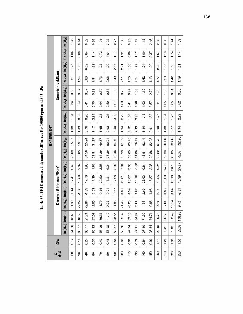
136
Ta
ble
36
. F
PJ
B m
easu
red
dy
na
mic
sti
ffn
esse
s fo
r 1
000
0 r
pm
an
d 3
45
kP
a
EX
PE
RIM
EN
T
Un
cert
ain
ty (
MN
/m)
Im(U
yy)
1.2
8
0.4
4
0.8
2
0.5
9
1.0
4
3.0
3
0.7
7
1.0
8
0.9
2
1.1
7
1.1
3
2.4
5
2.5
3
0.9
6
1.4
4
1.5
9
Re(U
yy)
1.0
6
0.6
9
0.6
4
1.1
4
0.7
2
4.6
4
1.1
7
1.3
1
0.6
6
1.1
2
1.0
0
2.3
7
1.5
7
1.1
3
1.7
4
1.1
4
Im(U
yx)
1.2
5
1.4
3
0.6
2
1.5
8
1.2
2
1.9
0
2.6
7
2.7
1
1.3
8
1.9
9
1.5
4
1.2
9
2.6
3
1.5
5
1.6
6
1.6
1
Re(U
yx)
2.5
1
1.2
4
0.8
6
1.8
1
1.7
3
0.9
8
2.4
9
2.2
1
1.5
5
2.7
4
1.4
2
1.1
3
1.7
7
2.5
0
1.4
2
1.1
9
Im(U
xy)
0.6
9
0.8
9
0.6
7
0.6
8
0.7
0
0.5
6
1.0
0
0.7
0
0.9
4
1.0
6
1.1
5
2.7
2
1.2
6
1.0
3
0.8
1
0.6
5
Re(U
xy)
0.5
4
0.7
4
0.4
1
0.7
0
0.6
4
0.5
9
1.0
1
1.0
9
0.4
1
1.2
6
1.6
3
3.5
7
3.1
1
1.0
5
0.8
5
0.8
2
Im(U
xx)
1.3
1
0.8
8
0.9
0
2.8
9
1.2
6
1.2
1
3.0
0
2.2
2
1.6
7
2.3
5
1.4
8
1.3
2
1.7
7
1.6
1
1.7
0
2.2
9
Re(U
xx)
1.0
8
1.0
3
0.7
6
1.1
7
1.6
5
0.9
2
3.4
0
1.9
4
2.5
2
2.3
3
1.3
4
0.9
1
2.0
0
1.8
8
0.7
7
1.9
4
Dyn
am
ic S
tiff
ness (
MN
/m)
Im(H
yy)
15.9
7
19.3
5
25.2
4
31.6
7
40.8
7
82.0
4
54.4
0
61.8
2
65.7
5
79.6
9
82.1
4
82.2
8
97.7
3
109.1
6
138.1
5
132.9
0
Re(H
yy)
76.0
9
75.8
5
74.5
0
71.8
1
66.2
9
25.3
0
69.4
8
60.9
9
56.6
5
51.0
0
42.8
1
29.8
6
27.2
9
12.3
3
26.8
5
-5.0
7
Im(H
yx)
0.4
2
2.0
7
1.9
5
1.6
2
2.5
8
6.3
4
2.9
4
7.0
4
3.8
0
-1.6
0
0.8
4
2.3
5
9.2
4
14.0
9
20.1
9
25.8
7
Re(H
yx)
17.4
1
16.6
8
17.7
6
17.3
9
20.5
0
16.3
1
17.9
8
23.8
1
23.0
7
24.1
8
22.6
3
18.8
7
16.2
5
18.0
0
20.1
8
18.9
9
Im(H
xy)
-1.4
4
-1.8
6
-1.8
9
-2.0
3
-0.9
4
-0.2
1
-0.6
7
0.0
0
0.3
4
2.6
7
2.6
6
4.9
6
2.4
1
0.8
8
0.0
4
-2.3
1
Re(H
xy)
-1.9
9
-2.2
9
-2.8
4
-2.8
0
-1.7
9
0.2
5
-1.8
3
-1.4
3
-0.2
0
2.1
9
1.3
5
-0.8
6
2.5
0
6.1
3
10.2
4
9.7
2
Im(H
xx)
12.4
2
16.5
5
21.7
4
27.0
1
36.3
2
41.1
9
48.5
5
52.6
9
59.1
0
64.3
7
71.3
0
74.7
4
86.7
5
96.5
8
92.4
7
108.9
8
Re(H
xx)
61.2
0
60.7
7
60.7
7
60.6
2
57.0
6
55.9
2
50.3
7
55.7
6
47.8
4
47.8
1
37.9
0
36.3
4
22.4
3
0.4
5
1.1
3
-35.6
2
Ω/ω
0.1
2
0.1
8
0.2
4
0.3
0
0.4
2
0.4
8
0.5
4
0.6
0
0.6
6
0.7
8
0.8
4
0.9
0
1.1
4
1.2
6
1.3
8
1.5
0
Ω
(Hz)
20
30
40
50
70
80
90
100
110
130
140
150
190
210
230
250
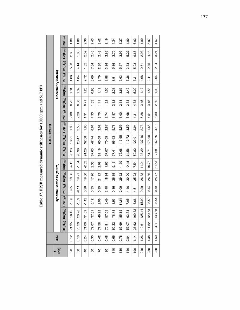
137
Ta
ble
37
. F
PJ
B m
easu
red
dy
na
mic
sti
ffn
esse
s fo
r 1
000
0 r
pm
an
d 5
17
kP
a
EX
PE
RIM
EN
T
Un
cert
ain
ty (
MN
/m)
Im(U
yy)
1.8
0
1.8
0
2.3
6
2.4
3
3.4
2
3.1
9
4.3
4
3.2
7
4.8
0
6.0
3
4.8
9
5.9
7
4.6
7
Re(U
yy)
2.6
3
1.8
5
2.5
2
2.4
3
2.4
8
2.8
6
3.7
5
3.9
5
5.2
9
6.6
6
2.9
3
4.1
8
3.2
4
Im(U
yx)
5.0
8
4.1
4
1.6
2
7.8
4
2.8
0
3.3
6
5.3
6
5.6
7
3.3
3
5.0
3
2.6
1
2.4
5
2.0
4
Re(U
yx)
4.8
6
4.0
4
2.7
2
5.6
9
3.7
9
2.9
8
3.9
1
5.6
3
3.2
6
3.2
1
4.6
8
2.4
1
2.0
4
Im(U
xy)
1.3
1
1.3
2
1.2
0
0.9
5
1.1
2
1.5
0
2.3
3
3.6
9
3.4
9
5.2
0
1.1
7
1.5
3
1.9
0
Re(U
xy)
0.7
2
0.8
0
0.7
1
1.6
3
1.4
1
1.6
2
2.3
2
2.3
8
3.8
8
4.8
8
3.4
5
3.1
5
2.5
0
Im(U
xx)
2.8
8
2.2
9
1.9
1
4.9
3
3.7
0
2.7
4
3.8
7
8.0
0
5.6
8
4.3
1
5.2
8
4.5
1
6.3
9
Re(U
xx)
1.3
0
2.5
5
1.9
8
6.6
1
3.0
2
2.8
7
5.7
8
5.5
9
3.5
9
2.9
4
2.7
3
1.6
5
4.1
9
Dyn
am
ic S
tiff
ness (
MN
/m)
Im(H
yy)
16.9
1
23.4
7
32.3
8
42.7
4
60.0
8
70.0
5
96.6
3
113.6
5
112.7
2
122.0
1
137.1
6
176.0
8
162.7
5
Re(H
yy)
95.2
3
93.9
6
91.2
6
87.6
3
82.1
6
57.0
7
77.4
1
75.6
8
64.5
6
50.8
2
38.2
9
51.7
1
7.5
9
Im(H
yx)
-4.1
1
-1.8
4
-2.0
2
2.3
5
2.6
9
1.6
5
5.1
6
-1.9
0
-0.4
8
7.5
4
11.2
4
19.7
8
31.5
4
Re(H
yx)
18.3
6
19.2
1
19.8
0
17.2
6
21.2
2
18.8
4
26.8
9
29.9
2
30.0
0
25.2
3
26.3
3
26.8
6
25.7
7
Im(H
xy)
0.0
5
-0.1
1
0.2
8
0.3
5
0.9
5
2.4
0
0.3
6
2.0
9
4.4
6
4.5
1
0.2
9
-2.6
7
-3.8
1
Re(H
xy)
-1.8
0
-1.3
9
-1.1
2
0.1
2
2.9
6
5.4
9
8.9
3
11.6
1
7.0
5
6.6
6
15.9
2
22.5
0
22.5
4
Im(H
xx)
18.4
5
23.7
6
31.0
9
37.8
1
49.2
2
57.0
5
78.7
8
85.1
5
93.7
3
109.8
2
125.4
4
120.5
3
143.5
8
Re(H
xx)
71.9
5
70.2
3
71.0
9
72.0
7
71.5
8
70.8
1
65.2
2
65.6
9
53.0
7
36.6
2
10.6
1
11.5
2
-24.3
9
Ω/ω
0.1
2
0.1
8
0.2
4
0.3
0
0.4
2
0.4
8
0.6
6
0.7
8
0.8
4
1.1
4
1.2
6
1.3
8
1.5
0
Ω
(Hz)
20
30
40
50
70
80
110
130
140
190
210
230
250

138
Ta
ble
38
. F
PJ
B m
easu
red
dy
na
mic
sti
ffn
esse
s fo
r 1
000
0 r
pm
an
d 6
89
kP
a
EX
PE
RIM
EN
T
Un
cert
ain
ty (
MN
/m)
Im(U
yy)
2.5
0
3.5
5
2.1
9
1.5
7
2.6
2
2.8
6
2.2
2
1.7
5
3.2
0
2.6
3
1.4
9
1.8
8
2.3
4
2.5
0
3.0
2
4.2
7
Re(U
yy)
2.3
6
2.5
0
3.3
9
1.8
3
2.2
4
2.3
7
3.0
3
3.1
0
6.2
7
3.6
5
2.2
7
1.7
5
3.5
6
1.9
1
1.8
8
2.0
7
Im(U
yx)
7.5
8
3.8
9
3.3
0
5.9
2
2.4
1
4.4
1
5.1
6
4.6
9
3.0
4
4.9
2
4.2
7
3.0
6
2.0
8
1.9
9
4.2
5
1.7
5
Re(U
yx)
4.3
7
5.5
8
3.8
9
3.3
2
4.4
7
5.1
2
5.7
7
2.4
0
4.0
5
7.6
3
2.7
6
3.6
9
1.4
2
1.4
1
3.2
4
2.1
3
Im(U
xy)
1.6
6
2.0
5
1.7
2
1.6
4
1.4
4
2.9
5
1.8
0
2.9
6
6.9
3
3.2
7
2.6
8
2.1
0
2.3
9
1.8
3
0.8
5
1.3
5
Re(U
xy)
1.6
6
1.9
0
1.6
9
1.7
2
1.8
0
2.3
4
2.6
1
2.9
0
4.3
3
4.1
0
2.8
9
0.8
2
2.1
1
0.8
0
1.3
5
1.1
7
Im(U
xx)
4.4
2
3.2
3
2.6
2
2.6
8
2.8
1
2.9
1
6.7
3
5.1
3
4.5
6
11.2
0
5.6
0
5.0
8
1.6
2
3.6
5
7.1
8
5.1
2
Re(U
xx)
2.8
2
2.5
3
3.2
6
3.7
1
3.3
2
4.7
5
6.2
4
4.5
9
2.9
1
11.3
1
3.3
4
6.2
8
2.5
3
1.5
9
9.2
0
3.4
4
Dyn
am
ic S
tiff
ness (
MN
/m)
Im(H
yy)
18.3
4
25.5
3
35.3
0
67.2
2
77.1
6
109.0
0
131.0
7
130.8
9
130.5
2
148.5
7
154.0
9
155.1
2
199.7
2
178.5
7
186.8
4
268.2
4
Re(H
yy)
122.8
5
121.3
5
117.9
8
108.1
0
91.4
3
105.9
2
107.8
5
98.4
6
81.1
5
82.5
3
64.9
1
50.9
5
82.7
9
33.0
6
23.6
3
41.2
4
Im(H
yx)
-9.0
5
-3.4
2
-6.0
8
4.4
9
1.8
9
4.1
2
-3.2
9
-2.4
8
-1.3
2
5.3
2
7.6
3
11.4
5
16.1
5
27.9
8
35.6
3
52.6
5
Re(H
yx)
19.7
7
19.5
8
20.8
4
21.6
7
19.1
9
31.3
3
34.0
9
34.7
7
29.7
6
25.0
3
29.9
1
16.9
8
32.1
8
30.4
3
31.8
5
30.4
7
Im(H
xy)
0.9
1
0.9
8
1.2
0
1.8
5
2.0
2
-2.1
5
-5.9
1
-4.2
7
0.9
4
-3.7
0
-2.9
9
-1.1
7
-7.4
5
-6.6
4
-6.3
1
-14.1
5
Re(H
xy)
-2.3
7
-1.0
8
-0.3
4
6.3
0
9.0
4
14.7
3
18.1
9
17.0
0
16.2
4
28.1
1
24.1
2
24.9
6
29.9
5
28.2
5
30.8
2
26.4
9
Im(H
xx)
21.4
7
26.6
4
35.7
1
52.0
0
62.3
1
82.8
3
86.3
4
97.6
2
102.5
5
168.9
3
137.4
1
145.9
5
130.0
6
155.8
7
152.1
8
143.6
5
Re(H
xx)
87.3
2
86.8
3
86.5
3
90.8
6
91.4
3
83.8
9
83.4
9
68.7
9
67.8
6
12.1
9
26.7
8
13.7
6
27.0
1
-9.2
2
-63.6
8
-48.4
8
Ω/ω
0.1
2
0.1
8
0.2
4
0.4
2
0.4
8
0.6
6
0.7
8
0.8
4
0.9
0
1.2
0
1.2
6
1.3
2
1.3
8
1.5
0
1.5
6
1.6
8
Ω
(Hz)
20
30
40
70
80
110
130
140
150
200
210
220
230
250
260
280
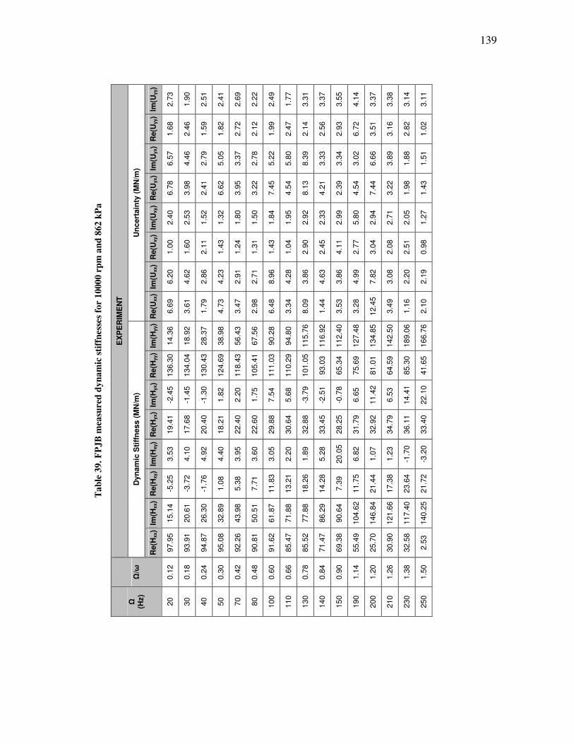
139
Ta
ble
39
. F
PJ
B m
easu
red
dy
na
mic
sti
ffn
esse
s fo
r 1
000
0 r
pm
an
d 8
62
kP
a
EX
PE
RIM
EN
T
Un
cert
ain
ty (
MN
/m)
Im(U
yy)
2.7
3
1.9
0
2.5
1
2.4
1
2.6
9
2.2
2
2.4
9
1.7
7
3.3
1
3.3
7
3.5
5
4.1
4
3.3
7
3.3
8
3.1
4
3.1
1
Re(U
yy)
1.6
8
2.4
6
1.5
9
1.8
2
2.7
2
2.1
2
1.9
9
2.4
7
2.1
4
2.5
6
2.9
3
6.7
2
3.5
1
3.1
6
2.8
2
1.0
2
Im(U
yx)
6.5
7
4.4
6
2.7
9
5.0
5
3.3
7
2.7
8
5.2
2
5.8
0
8.3
9
3.3
3
3.3
4
3.0
2
6.6
6
3.8
9
1.8
8
1.5
1
Re(U
yx)
6.7
8
3.9
8
2.4
1
6.6
2
3.9
5
3.2
2
7.4
5
4.5
4
8.1
3
4.2
1
2.3
9
4.5
4
7.4
4
3.2
2
1.9
8
1.4
3
Im(U
xy)
2.4
0
2.5
3
1.5
2
1.3
2
1.8
0
1.5
0
1.8
4
1.9
5
2.9
2
2.3
3
2.9
9
5.8
0
2.9
4
2.7
1
2.0
5
1.2
7
Re(U
xy)
1.0
0
1.6
0
2.1
1
1.4
3
1.2
4
1.3
1
1.4
3
1.0
4
2.9
0
2.4
5
4.1
1
2.7
7
3.0
4
2.0
8
2.5
1
0.9
8
Im(U
xx)
6.2
0
4.6
2
2.8
6
4.2
3
2.9
1
2.7
1
8.9
6
4.2
8
3.8
6
4.6
3
3.8
6
4.9
9
7.8
2
3.0
8
2.2
0
2.1
9
Re(U
xx)
6.6
9
3.6
1
1.7
9
4.7
3
3.4
7
2.9
8
6.4
8
3.3
4
8.0
9
1.4
4
3.5
3
3.2
8
12.4
5
3.4
9
1.1
6
2.1
0
Dyn
am
ic S
tiff
ness (
MN
/m)
Im(H
yy)
14.3
6
18.9
2
28.3
7
38.9
8
56.4
3
67.5
6
90.2
8
94.8
0
115.7
6
116.9
2
112.4
0
127.4
8
134.8
5
142.5
0
189.0
6
166.7
6
Re(H
yy)
136.3
0
134.0
4
130.4
3
124.6
9
118.4
3
105.4
1
111.0
3
110.2
9
101.0
5
93.0
3
65.3
4
75.6
9
81.0
1
64.5
9
85.3
0
41.6
5
Im(H
yx)
-2.4
5
-1.4
5
-1.3
0
1.8
2
2.2
0
1.7
5
7.5
4
5.6
8
-3.7
9
-2.5
1
-0.7
8
6.6
5
11.4
2
6.5
3
14.4
1
22.1
0
Re(H
yx)
19.4
1
17.6
8
20.4
0
18.2
1
22.4
0
22.6
0
29.8
8
30.6
4
32.8
8
33.4
5
28.2
5
31.7
9
32.9
2
34.7
9
36.1
1
33.4
0
Im(H
xy)
3.5
3
4.1
0
4.9
2
4.4
0
3.9
5
3.6
0
3.0
5
2.2
0
1.8
9
5.2
8
20.0
5
6.8
2
1.0
7
1.2
3
-1.7
0
-3.2
0
Re(H
xy)
-5.2
5
-3.7
2
-1.7
6
1.0
8
5.3
8
7.7
1
11.8
3
13.2
1
18.2
6
14.2
8
7.3
9
11.7
5
21.4
4
17.3
8
23.6
4
21.7
2
Im(H
xx)
15.1
4
20.6
1
26.3
0
32.8
9
43.9
8
50.5
1
61.8
7
71.8
8
77.8
8
86.2
9
90.6
4
104.6
2
146.8
4
121.6
6
117.4
0
140.2
5
Re(H
xx)
97.9
5
93.9
1
94.8
7
95.0
8
92.2
6
90.8
1
91.6
2
85.4
7
85.5
2
71.4
7
69.3
8
55.4
9
25.7
0
30.9
0
32.5
8
2.5
3
Ω/ω
0.1
2
0.1
8
0.2
4
0.3
0
0.4
2
0.4
8
0.6
0
0.6
6
0.7
8
0.8
4
0.9
0
1.1
4
1.2
0
1.2
6
1.3
8
1.5
0
Ω
(Hz)
20
30
40
50
70
80
100
110
130
140
150
190
200
210
230
250
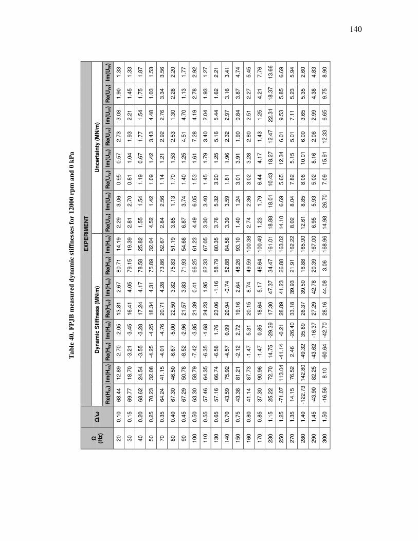
140
Ta
ble
40
. F
PJ
B m
easu
red
dy
na
mic
sti
ffn
esse
s fo
r 1
200
0 r
pm
an
d 0
kP
a
EX
PE
RIM
EN
T
Un
cert
ain
ty (
MN
/m)
Im(U
yy)
1.3
3
1.3
3
1.8
7
1.5
3
3.5
6
2.2
0
1.7
7
2.9
2
1.2
7
2.2
1
3.4
1
4.7
4
5.4
5
7.7
6
13.6
6
6.6
9
5.9
4
2.6
0
4.8
3
8.9
0
Re(U
yy)
1.9
0
1.4
5
1.7
5
1.0
3
3.3
4
2.2
8
1.1
3
2.7
8
1.9
3
1.6
2
3.1
6
3.8
7
2.2
7
4.2
1
18.3
7
5.8
5
5.2
3
5.3
5
4.3
8
9.7
5
Im(U
yx)
3.0
8
2.2
1
1.5
4
4.4
8
2.7
6
1.3
0
4.7
0
4.1
9
2.0
4
5.4
4
2.9
7
0.8
4
2.5
1
1.2
5
22.3
1
9.5
3
7.1
1
3.6
5
2.9
9
6.6
5
Re(U
yx)
2.7
3
1.9
3
1.7
7
3.4
3
2.9
2
2.5
3
4.5
1
7.2
8
3.4
0
5.1
6
2.3
2
1.9
0
2.8
0
1.4
3
12.4
7
6.0
1
5.0
1
6.0
0
2.0
6
12.3
3
Im(U
xy)
0.5
7
1.0
4
0.6
7
1.4
2
1.2
1
1.5
3
1.2
5
1.6
1
1.7
9
1.2
5
1.9
6
3.9
1
3.2
8
4.1
7
18.2
7
12.3
4
5.1
5
10.0
1
8.1
6
15.9
1
Re(U
xy)
0.9
5
0.8
1
1.1
9
1.0
9
1.1
4
1.7
0
1.4
0
1.5
3
1.4
5
3.2
0
1.8
1
3.0
1
3.0
2
6.4
4
10.4
3
5.6
5
7.8
2
8.0
6
5.0
2
7.0
9
Im(U
xx)
3.0
6
2.7
0
1.5
4
1.4
2
2.5
6
1.1
3
3.7
4
6.0
5
3.4
0
5.3
2
3.5
9
1.2
4
2.3
6
1.7
9
18.0
1
6.6
9
8.0
4
8.8
5
5.9
3
26.7
0
Re(U
xx)
2.2
9
2.8
1
1.5
5
4.5
2
2.8
4
3.8
5
6.8
7
4.4
9
3.3
0
3.7
6
3.3
9
1.4
0
2.7
4
1.2
3
18.8
8
14.1
0
8.0
2
12.6
1
6.9
5
14.9
8
Dyn
am
ic S
tiff
ness (
MN
/m)
Im(H
yy)
14.1
9
19.3
9
25.8
2
32.0
4
52.6
7
51.1
9
54.6
8
61.2
3
67.0
5
80.3
5
84.5
8
93.1
0
100.3
8
100.4
9
161.0
1
163.0
2
162.2
2
165.9
0
167.0
0
168.9
6
Re(H
yy)
80.7
1
79.1
5
78.5
8
75.8
9
73.8
6
75.8
3
71.9
3
66.2
5
62.3
3
58.7
9
52.8
8
48.2
6
49.5
9
46.6
4
34.4
7
26.8
8
21.9
1
16.8
8
20.3
9
3.0
6
Im(H
yx)
2.6
7
4.0
5
4.1
7
4.3
1
4.2
8
3.8
2
3.8
3
0.4
1
1.9
5
-1.1
6
-0.7
4
2.6
4
8.7
4
5.1
7
47.3
7
41.2
3
39.9
3
39.5
0
42.7
8
44.0
8
Re(H
yx)
13.8
1
16.4
1
17.2
4
18.3
4
20.7
1
22.5
0
21.5
7
21.3
9
24.2
3
23.0
6
20.9
4
19.1
6
20.1
5
18.6
4
17.3
0
28.8
9
33.1
8
26.3
7
27.2
9
28.1
6
Im(H
xy)
-2.0
5
-3.4
5
-3.2
8
-4.2
5
-4.7
6
-5.0
0
-2.9
6
-3.8
5
-1.6
8
1.7
6
0.9
9
2.7
2
5.3
1
0.8
5
-29.3
9
-0.2
1
-26.4
0
35.8
9
-16.3
7
-42.7
0
Re(H
xy)
-2.7
0
-3.2
1
-3.5
5
-4.2
5
-4.0
1
-6.6
7
-8.5
2
-7.4
2
-6.3
5
-6.5
6
-4.5
7
-2.1
2
-1.4
7
-1.4
7
14.7
5
-41.1
4
2.4
6
-49.3
2
-43.6
2
-60.6
4
Im(H
xx)
12.8
9
18.7
0
24.5
4
32.0
8
41.1
5
46.5
0
50.7
8
58.7
9
64.3
5
66.7
4
75.9
2
81.2
1
87.7
3
90.9
6
72.7
0
113.0
4
76.5
2
142.8
0
82.2
5
8.1
0
Re(H
xx)
68.4
4
69.7
7
68.6
2
70.2
3
64.2
4
67.3
0
67.2
9
63.3
0
57.4
6
57.1
6
43.5
9
43.3
8
41.1
4
37.3
0
25.2
2
-71.0
7
14.1
5
-122.7
3
-43.9
0
-16.5
6
Ω/ω
0.1
0
0.1
5
0.2
0
0.2
5
0.3
5
0.4
0
0.4
5
0.5
0
0.5
5
0.6
5
0.7
0
0.7
5
0.8
0
0.8
5
1.1
5
1.2
5
1.3
5
1.4
0
1.4
5
1.5
0
Ω
(Hz)
20
30
40
50
70
80
90
100
110
130
140
150
160
170
230
250
270
280
290
300

141
Ta
ble
41
. F
PJ
B m
easu
red
dy
na
mic
sti
ffn
esse
s fo
r 1
200
0 r
pm
an
d 1
72
kP
a
EX
PE
RIM
EN
T
Un
cert
ain
ty (
MN
/m)
Im(U
yy)
1.2
7
1.0
0
1.0
1
1.0
4
0.8
0
1.2
8
1.2
6
1.9
4
1.3
1
1.7
0
1.7
8
5.5
2
1.7
4
3.6
5
2.2
3
2.7
0
1.7
7
Re(U
yy)
1.3
0
1.9
3
1.3
0
1.3
9
1.4
1
4.1
7
1.3
5
1.2
3
1.4
6
1.0
8
2.2
5
2.3
8
1.8
4
3.8
5
2.9
4
2.3
9
2.7
6
Im(U
yx)
2.5
4
1.8
0
1.3
7
2.7
4
1.9
0
1.7
4
2.2
1
3.3
7
1.9
7
2.0
8
1.0
5
2.0
0
0.8
6
1.9
5
3.4
8
2.1
1
3.3
1
Re(U
yx)
2.5
3
2.0
7
1.1
4
3.5
1
1.7
5
3.1
3
3.3
6
2.4
6
3.6
2
1.4
8
1.0
9
2.1
6
0.6
9
3.8
7
3.2
7
2.2
7
3.4
5
Im(U
xy)
0.7
5
1.1
9
1.2
1
0.8
6
1.1
2
2.2
3
0.8
0
1.6
2
1.6
8
1.4
3
1.2
8
1.6
7
2.4
3
5.4
5
5.7
0
1.8
0
6.3
7
Re(U
xy)
1.6
1
1.2
3
0.8
4
0.9
5
1.3
0
1.8
1
1.6
8
1.2
2
1.4
4
1.0
4
1.4
3
1.8
6
2.1
3
4.7
2
3.5
1
1.6
2
3.4
6
Im(U
xx)
2.2
1
2.6
4
1.3
7
3.7
7
2.0
5
2.1
2
4.0
3
2.6
2
3.2
1
1.3
2
1.4
1
1.7
8
1.4
9
4.8
0
4.1
9
3.1
0
12.7
1
Re(U
xx)
1.6
3
1.6
2
1.2
6
3.0
1
2.6
0
2.5
7
2.9
1
3.1
3
3.8
0
1.7
7
0.6
7
1.2
5
1.0
2
3.3
7
4.1
6
2.6
2
7.8
1
Dyn
am
ic S
tiff
ness (
MN
/m)
Im(H
yy)
14.1
0
18.1
9
24.1
9
29.5
3
37.6
9
66.1
1
51.1
8
60.9
4
71.8
3
76.2
2
80.1
4
100.7
2
96.9
2
96.1
5
100.7
4
134.3
3
129.2
1
Re(H
yy)
82.3
2
81.5
2
80.1
3
77.9
8
71.8
1
95.3
7
73.9
1
63.9
8
55.7
0
47.0
0
30.9
2
57.5
6
44.3
2
30.6
2
4.4
3
28.1
7
-5.1
6
Im(H
yx)
3.3
9
4.4
1
3.1
5
3.3
2
2.2
8
5.7
1
2.6
8
2.6
4
-0.6
5
1.0
8
4.0
4
5.4
4
6.3
9
7.0
2
8.1
2
19.9
3
11.9
8
Re(H
yx)
14.3
4
16.4
6
16.9
7
17.5
5
19.1
5
23.3
6
20.3
8
22.8
9
23.1
9
21.5
2
17.4
8
21.7
3
21.1
1
19.1
6
16.1
1
19.3
3
13.1
2
Im(H
xy)
-1.3
6
-2.8
2
-2.3
5
-3.0
7
-2.5
5
-5.5
2
-2.6
2
-2.1
6
0.6
0
1.2
0
2.7
5
1.8
8
2.7
5
2.0
4
-0.1
8
-1.8
8
-36.2
6
Re(H
xy)
-5.0
1
-4.8
7
-5.4
6
-6.0
7
-5.3
8
-5.3
3
-6.0
5
-5.7
1
-4.5
8
-3.7
8
-3.0
4
-0.1
1
0.1
2
0.4
8
3.7
7
11.1
4
7.6
6
Im(H
xx)
13.4
4
17.9
7
22.7
3
27.3
4
37.0
4
40.8
5
46.6
0
56.8
6
58.6
0
68.2
7
71.4
0
75.9
9
79.6
2
82.5
1
90.0
5
87.9
9
71.1
9
Re(H
xx)
69.3
4
70.1
6
69.7
9
69.5
0
67.5
2
65.7
9
63.2
3
58.8
3
56.5
5
47.2
7
45.0
8
41.0
3
37.6
2
29.7
8
9.5
2
15.1
5
-29.1
9
Ω/ω
0.1
0
0.1
5
0.2
0
0.2
5
0.3
5
0.4
0
0.4
5
0.5
5
0.6
5
0.7
0
0.7
5
0.8
0
0.8
5
0.9
5
1.0
5
1.1
5
1.2
5
Ω
(Hz)
20
30
40
50
70
80
90
110
130
140
150
160
170
190
210
230
250

142
Ta
ble
42
. F
PK
B m
easu
red
dy
na
mic
sti
ffn
esse
s fo
r 1
200
0 r
pm
an
d 3
45
kP
a
EX
PE
RIM
EN
T
Un
cert
ain
ty (
MN
/m)
Im(U
yy)
1.9
6
1.5
0
1.5
3
2.5
0
2.8
8
3.5
5
2.9
7
3.4
9
3.5
8
2.0
2
3.7
6
4.0
6
5.5
2
3.1
3
2.4
7
Re(U
yy)
1.3
8
1.3
7
2.1
9
1.6
1
2.8
9
1.9
0
2.4
5
2.7
9
1.7
8
2.3
4
1.8
8
3.1
1
3.6
6
3.4
9
4.1
3
Im(U
yx)
3.8
2
3.0
2
1.8
0
5.6
1
4.0
0
5.0
1
7.7
7
3.4
7
5.9
2
2.3
1
1.9
6
3.5
3
2.1
3
2.8
2
2.5
2
Re(U
yx)
4.7
1
4.1
1
2.4
1
5.0
3
3.8
4
6.3
7
4.6
4
5.2
9
3.9
5
2.7
1
2.6
7
2.0
3
2.6
4
4.0
2
2.3
5
Im(U
xy)
1.0
6
1.1
3
1.2
9
0.9
6
1.2
0
2.3
4
2.1
7
2.4
4
2.0
3
1.3
3
0.5
0
2.2
0
3.7
9
3.2
9
2.8
3
Re(U
xy)
0.5
2
0.9
0
1.0
1
1.5
0
1.8
5
2.1
0
2.3
7
1.9
3
2.3
8
1.5
2
2.1
9
3.9
3
5.1
5
3.1
5
2.2
7
Im(U
xx)
2.2
2
2.3
8
1.7
4
4.0
4
3.3
1
6.9
1
6.8
6
5.3
6
4.9
5
3.0
4
2.8
5
2.0
8
2.8
7
6.7
0
2.3
4
Re(U
xx)
2.4
6
1.7
0
1.3
2
4.7
6
3.3
3
7.2
4
6.7
9
3.7
7
4.1
5
1.8
4
2.3
2
3.0
9
2.3
2
5.1
3
2.7
9
Dyn
am
ic S
tiff
ness (
MN
/m)
Im(H
yy)
20.4
3
28.9
3
37.7
0
47.3
5
64.9
7
87.3
2
97.1
1
102.8
4
116.8
5
122.0
7
127.2
8
166.5
9
137.6
5
126.4
0
174.7
0
Re(H
yy)
87.8
6
86.9
5
86.0
8
83.0
1
79.0
7
85.3
0
78.0
8
75.4
0
74.1
5
66.8
4
55.4
6
86.8
9
66.2
9
20.8
5
60.8
9
Im(H
yx)
-1.6
8
1.2
6
-0.7
1
2.8
4
3.5
6
0.5
7
3.7
7
2.6
8
-8.5
5
-1.7
8
1.4
9
2.0
3
2.9
5
13.6
3
17.7
2
Re(H
yx)
18.0
5
19.4
7
20.9
3
19.1
0
24.6
9
23.1
4
31.4
6
30.9
2
32.9
3
30.9
2
27.1
8
27.0
4
27.6
4
13.4
3
22.8
4
Im(H
xy)
-1.1
8
-1.6
5
-1.6
4
-1.1
7
-0.3
5
0.0
2
0.3
8
1.0
2
1.4
2
2.1
6
4.0
9
5.2
6
5.8
4
-0.9
5
-2.6
3
Re(H
xy)
-0.5
1
-0.4
6
-0.9
9
-0.7
7
1.5
0
3.3
2
5.3
5
6.2
6
7.2
4
8.3
9
9.4
5
11.4
7
4.3
8
0.8
5
17.4
3
Im(H
xx)
19.9
4
26.3
2
35.4
2
42.1
5
54.8
3
67.5
6
74.1
6
86.6
9
93.3
1
106.6
5
109.4
5
119.1
5
121.7
1
135.7
7
132.6
1
Re(H
xx)
69.6
9
69.8
5
69.7
2
72.3
8
72.7
4
63.8
4
75.3
0
66.5
2
60.2
1
55.4
3
57.9
4
53.1
2
51.5
7
11.1
5
25.3
7
Ω/ω
0.1
0
0.1
5
0.2
0
0.2
5
0.3
5
0.4
5
0.5
0
0.5
5
0.6
5
0.7
0
0.7
5
0.8
0
0.8
5
1.1
0
1.1
5
Ω
(Hz)
20
30
40
50
70
90
100
110
130
140
150
160
170
220
230
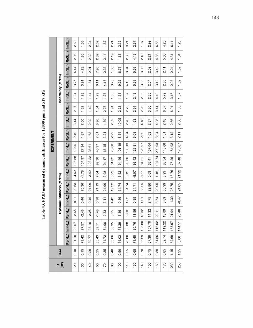
143
Ta
ble
43
. F
PJ
B m
easu
red
dy
na
mic
sti
ffn
esse
s fo
r 1
200
0 r
pm
an
d 5
17
kP
a
EX
PE
RIM
EN
T
Un
cert
ain
ty (
MN
/m)
Im(U
yy)
2.6
2
1.5
6
2.3
4
2.0
2
1.8
7
2.2
4
2.3
2
3.2
1
2.6
7
1.0
7
2.9
9
6.8
3
4.2
5
6.1
1
1.2
3
Re(U
yy)
2.0
6
1.8
5
2.3
2
2.8
2
3.1
4
2.1
9
1.8
8
2.3
0
4.1
3
2.4
9
2.2
1
4.3
3
5.6
0
4.3
1
1.8
4
Im(U
yx)
4.4
4
4.2
3
2.2
1
7.9
6
2.3
3
1.6
3
6.7
3
3.9
4
5.5
3
3.0
3
2.0
9
3.4
2
2.4
1
2.2
4
1.5
2
Re(U
yx)
3.7
5
3.9
1
1.8
1
6.1
1
4.1
6
3.7
0
9.2
2
4.1
3
5.6
8
3.3
8
2.0
4
3.1
2
2.8
0
2.9
7
1.8
2
Im(U
xy)
1.2
4
1.2
8
1.4
4
1.2
9
1.7
8
1.6
5
1.3
8
1.6
7
2.4
8
2.9
3
2.3
5
4.4
0
5.7
9
3.1
6
1.5
7
Re(U
xy)
2.0
7
1.6
2
1.4
2
1.5
4
2.2
7
1.9
1
2.2
3
2.7
9
2.5
4
2.2
3
3.8
0
3.4
4
6.5
7
6.0
1
1.6
5
Im(U
xx)
3.4
4
2.0
0
2.9
2
6.9
6
1.8
9
2.5
2
10.0
5
2.7
0
4.6
3
4.1
8
2.8
7
4.0
8
2.4
8
2.6
6
2.5
6
Re(U
xx)
2.4
9
1.8
7
1.6
3
7.6
1
3.2
1
2.2
2
8.5
4
4.3
4
6.0
9
2.6
9
1.6
3
3.0
4
1.5
1
3.1
2
2.1
1
Dyn
am
ic S
tiff
ness (
MN
/m)
Im(H
yy)
18.9
6
27.3
4
36.6
1
46.9
7
66.4
5
75.8
8
101.1
9
106.1
3
123.8
1
128.9
7
137.0
4
209.9
3
148.6
6
184.0
2
173.6
7
Re(H
yy)
106.8
8
104.9
7
103.2
2
99.3
6
94.1
7
61.8
2
94.4
6
90.8
6
92.4
2
84.2
1
68.4
1
104.7
4
83.5
4
78.2
6
37.4
8
Im(H
yx)
-4.6
2
-1.7
8
-3.4
2
2.6
4
3.9
8
3.2
9
5.5
2
3.1
9
-8.0
7
-1.1
1
0.6
9
1.4
6
3.9
9
15.7
6
21.9
2
Re(H
yx)
20.5
3
20.3
6
21.0
9
21.1
3
24.9
6
19.3
2
34.7
4
31.7
4
34.7
1
33.2
5
29.8
0
29.0
5
30.9
9
28.7
5
24.8
5
Im(H
xy)
-0.1
1
0.4
6
0.4
6
0.9
8
3.1
1
4.4
2
0.8
6
1.6
2
0.3
5
1.0
1
2.7
5
3.7
4
3.8
9
-1.3
9
-0.4
7
Re(H
xy)
-2.6
5
-2.4
6
-2.2
5
-1.4
8
2.3
3
5.2
5
8.3
6
9.6
0
11.5
6
13.3
2
14.3
2
22.1
1
13.0
9
21.0
4
25.4
6
Im(H
xx)
20.6
7
27.5
7
37.1
0
39.1
1
54.0
0
66.3
5
73.2
9
85.8
8
90.7
6
103.8
0
107.7
0
116.6
2
119.2
2
133.9
7
144.5
1
Re(H
xx)
81.1
0
79.4
2
80.7
7
85.4
3
84.7
2
83.8
6
86.0
3
78.8
8
71.4
5
65.2
9
67.3
8
64.2
6
62.7
4
32.6
9
3.8
0
Ω/ω
0.1
0
0.1
5
0.2
0
0.2
5
0.3
5
0.4
0
0.5
0
0.5
5
0.6
5
0.7
0
0.7
5
0.8
0
0.8
5
1.1
5
1.2
5
Ω
(Hz)
20
30
40
50
70
80
100
110
130
140
150
160
170
230
250
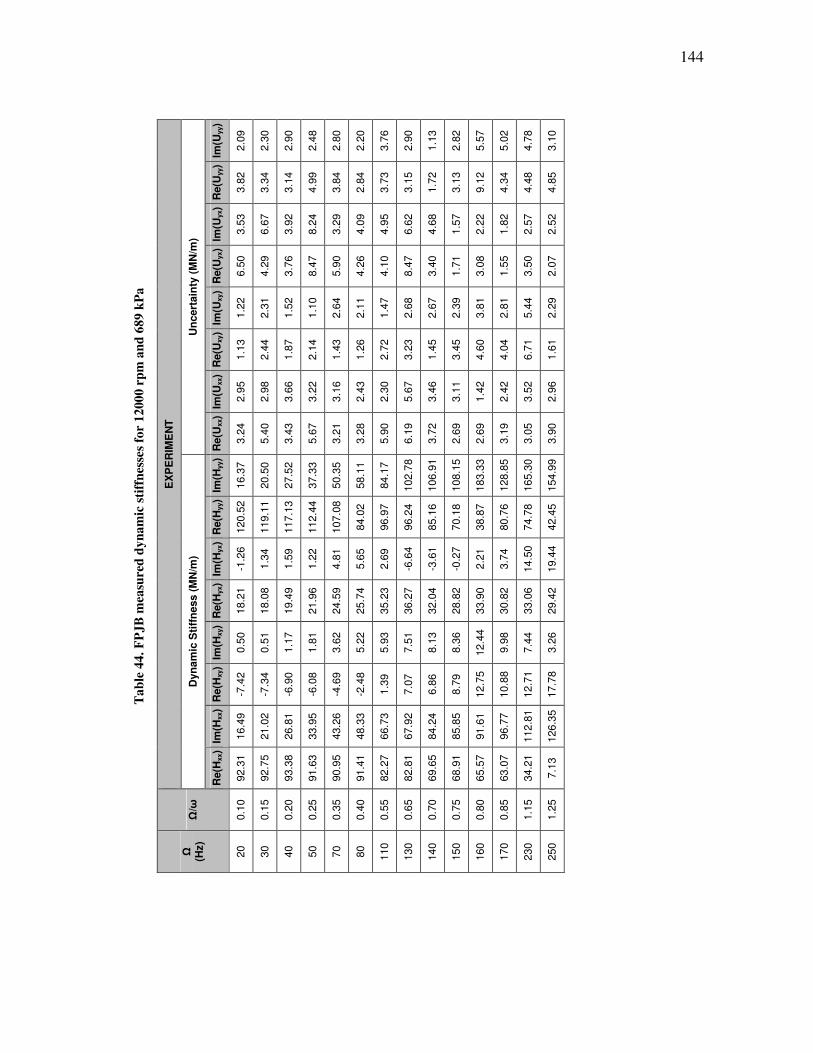
144
Ta
ble
44
. F
PJ
B m
easu
red
dy
na
mic
sti
ffn
esse
s fo
r 1
200
0 r
pm
an
d 6
89
kP
a
EX
PE
RIM
EN
T
Un
cert
ain
ty (
MN
/m)
Im(U
yy)
2.0
9
2.3
0
2.9
0
2.4
8
2.8
0
2.2
0
3.7
6
2.9
0
1.1
3
2.8
2
5.5
7
5.0
2
4.7
8
3.1
0
Re(U
yy)
3.8
2
3.3
4
3.1
4
4.9
9
3.8
4
2.8
4
3.7
3
3.1
5
1.7
2
3.1
3
9.1
2
4.3
4
4.4
8
4.8
5
Im(U
yx)
3.5
3
6.6
7
3.9
2
8.2
4
3.2
9
4.0
9
4.9
5
6.6
2
4.6
8
1.5
7
2.2
2
1.8
2
2.5
7
2.5
2
Re(U
yx)
6.5
0
4.2
9
3.7
6
8.4
7
5.9
0
4.2
6
4.1
0
8.4
7
3.4
0
1.7
1
3.0
8
1.5
5
3.5
0
2.0
7
Im(U
xy)
1.2
2
2.3
1
1.5
2
1.1
0
2.6
4
2.1
1
1.4
7
2.6
8
2.6
7
2.3
9
3.8
1
2.8
1
5.4
4
2.2
9
Re(U
xy)
1.1
3
2.4
4
1.8
7
2.1
4
1.4
3
1.2
6
2.7
2
3.2
3
1.4
5
3.4
5
4.6
0
4.0
4
6.7
1
1.6
1
Im(U
xx)
2.9
5
2.9
8
3.6
6
3.2
2
3.1
6
2.4
3
2.3
0
5.6
7
3.4
6
3.1
1
1.4
2
2.4
2
3.5
2
2.9
6
Re(U
xx)
3.2
4
5.4
0
3.4
3
5.6
7
3.2
1
3.2
8
5.9
0
6.1
9
3.7
2
2.6
9
2.6
9
3.1
9
3.0
5
3.9
0
Dyn
am
ic S
tiff
ness (
MN
/m)
Im(H
yy)
16.3
7
20.5
0
27.5
2
37.3
3
50.3
5
58.1
1
84.1
7
102.7
8
106.9
1
108.1
5
183.3
3
128.8
5
165.3
0
154.9
9
Re(H
yy)
120.5
2
119.1
1
117.1
3
112.4
4
107.0
8
84.0
2
96.9
7
96.2
4
85.1
6
70.1
8
38.8
7
80.7
6
74.7
8
42.4
5
Im(H
yx)
-1.2
6
1.3
4
1.5
9
1.2
2
4.8
1
5.6
5
2.6
9
-6.6
4
-3.6
1
-0.2
7
2.2
1
3.7
4
14.5
0
19.4
4
Re(H
yx)
18.2
1
18.0
8
19.4
9
21.9
6
24.5
9
25.7
4
35.2
3
36.2
7
32.0
4
28.8
2
33.9
0
30.8
2
33.0
6
29.4
2
Im(H
xy)
0.5
0
0.5
1
1.1
7
1.8
1
3.6
2
5.2
2
5.9
3
7.5
1
8.1
3
8.3
6
12.4
4
9.9
8
7.4
4
3.2
6
Re(H
xy)
-7.4
2
-7.3
4
-6.9
0
-6.0
8
-4.6
9
-2.4
8
1.3
9
7.0
7
6.8
6
8.7
9
12.7
5
10.8
8
12.7
1
17.7
8
Im(H
xx)
16.4
9
21.0
2
26.8
1
33.9
5
43.2
6
48.3
3
66.7
3
67.9
2
84.2
4
85.8
5
91.6
1
96.7
7
112.8
1
126.3
5
Re(H
xx)
92.3
1
92.7
5
93.3
8
91.6
3
90.9
5
91.4
1
82.2
7
82.8
1
69.6
5
68.9
1
65.5
7
63.0
7
34.2
1
7.1
3
Ω/ω
0.1
0
0.1
5
0.2
0
0.2
5
0.3
5
0.4
0
0.5
5
0.6
5
0.7
0
0.7
5
0.8
0
0.8
5
1.1
5
1.2
5
Ω
(Hz)
20
30
40
50
70
80
110
130
140
150
160
170
230
250

145
Ta
ble
45
. F
PJ
B m
easu
red
dy
na
mic
sti
ffn
esse
s fo
r 1
200
0 r
pm
an
d 8
62
kP
a
EX
PE
RIM
EN
T
Un
cert
ain
ty (
MN
/m)
Im(U
yy)
19.6
0
9.0
8
5.7
3
6.2
3
6.4
7
4.3
4
6.9
6
3.5
9
5.9
5
2.6
7
4.4
1
5.9
7
4.7
6
8.9
7
10.6
4
5.8
2
5.1
8
Re(U
yy)
19.4
5
9.0
1
8.5
0
6.6
7
4.3
1
4.3
1
5.4
2
5.3
8
1.8
3
7.6
9
4.2
6
1.7
7
4.2
1
6.4
1
7.2
3
5.1
4
2.4
1
Im(U
yx)
27.4
0
16.4
5
9.8
4
7.8
1
4.5
9
3.3
0
9.6
0
7.4
5
6.9
0
3.9
2
4.0
8
1.5
0
2.9
0
1.8
3
2.8
5
8.0
6
1.8
0
Re(U
yx)
18.6
8
6.3
7
5.9
7
12.0
1
6.9
3
4.6
6
7.7
5
6.5
8
2.5
8
6.1
1
3.0
8
2.2
9
2.1
1
1.9
2
2.9
2
5.7
9
1.5
3
Im(U
xy)
20.7
2
10.0
6
9.2
0
8.9
6
6.3
8
2.4
4
8.1
8
4.4
3
2.8
4
4.6
6
1.7
4
1.9
0
2.6
0
5.2
1
5.2
3
2.4
2
3.3
3
Re(U
xy)
23.2
1
9.0
2
13.0
1
8.2
0
5.7
9
4.1
5
4.8
6
6.8
8
2.8
1
6.6
4
2.4
0
3.6
9
2.8
1
5.9
6
8.5
8
4.9
2
3.2
2
Im(U
xx)
33.9
0
16.1
7
9.9
9
6.6
6
2.4
7
3.4
1
5.1
7
7.6
7
5.3
7
3.8
5
4.1
4
2.4
6
3.6
3
2.4
9
3.0
9
4.1
9
3.5
7
Re(U
xx)
18.9
8
10.8
1
8.3
5
12.1
0
7.8
9
6.1
1
4.4
3
5.3
8
3.2
5
6.3
4
2.2
6
1.8
0
1.4
0
1.0
9
2.2
0
4.0
6
2.0
8
Dyn
am
ic S
tiff
ness (
MN
/m)
Im(H
yy)
-26.2
4
-13.2
4
3.1
5
14.3
5
29.9
2
40.8
2
50.3
7
60.3
7
63.5
6
91.6
9
88.3
8
92.0
0
122.0
7
111.1
1
163.5
0
140.8
1
147.9
6
Re(H
yy)
147.0
9
132.6
7
128.4
2
125.9
4
115.1
1
100.1
5
120.3
8
108.4
4
106.2
9
96.0
2
89.1
1
75.1
1
79.0
0
82.1
1
82.8
7
49.5
3
47.0
7
Im(H
yx)
34.8
5
30.4
1
24.1
7
17.4
0
13.3
3
12.5
6
11.2
0
11.3
6
4.4
3
-2.6
8
-1.1
2
1.0
5
5.6
4
3.1
5
15.4
1
17.8
8
18.6
9
Re(H
yx)
8.6
3
16.6
7
23.1
5
27.5
7
33.8
2
35.0
0
38.5
0
41.3
4
42.9
5
43.0
9
38.6
2
34.5
9
36.7
7
35.6
4
37.7
1
31.1
5
34.6
2
Im(H
xy)
42.2
0
35.1
3
26.8
0
23.2
8
18.1
7
15.6
6
12.8
5
14.1
7
13.2
6
10.3
1
13.6
9
12.3
4
12.9
2
13.0
4
8.9
2
5.3
2
7.4
3
Re(H
xy)
-26.7
3
-10.9
8
-9.2
1
-4.4
5
0.6
3
2.2
1
4.3
9
4.7
6
3.3
5
12.0
4
9.2
5
10.0
7
16.3
1
15.0
5
20.4
3
15.6
7
18.1
9
Im(H
xx)
-17.9
3
-10.0
1
0.6
8
11.7
0
28.3
2
32.9
5
40.1
1
45.7
0
51.0
9
50.8
0
67.5
4
71.7
2
77.0
1
82.2
8
100.4
3
95.1
6
118.5
9
Re(H
xx)
114.8
2
105.1
9
100.2
7
98.8
9
92.6
9
93.1
3
86.0
6
93.9
2
83.4
9
82.0
8
70.4
6
67.6
7
64.6
2
62.3
5
35.2
8
27.4
1
8.3
7
Ω/ω
0.1
0
0.1
5
0.2
0
0.2
5
0.3
5
0.4
0
0.4
5
0.5
0
0.5
5
0.6
5
0.7
0
0.7
5
0.8
0
0.8
5
1.1
5
1.2
0
1.2
5
Ω
(Hz)
20
30
40
50
70
80
90
100
110
130
140
150
160
170
230
240
250
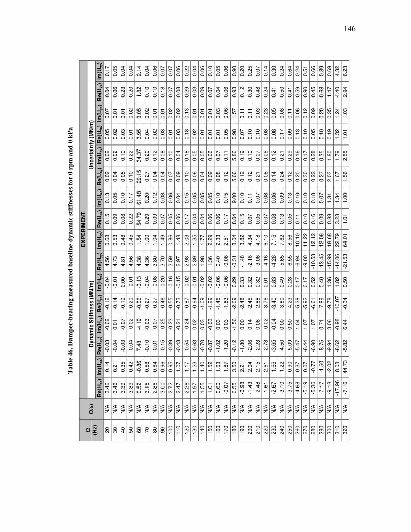
146
Ta
ble
46
. D
am
per
-bea
rin
g m
easu
red
ba
seli
ne
dy
na
mic
sti
ffn
esse
s fo
r 0
rp
m a
nd
0 k
Pa
EX
PE
RIM
EN
T
Un
cert
ain
ty (
MN
/m)
Im(U
yy)
0.1
7
0.0
5
0.0
4
0.0
4
2.1
4
0.0
4
0.0
6
0.0
7
0.0
7
0.0
6
0.2
2
0.0
4
0.0
6
0.1
0
0.0
5
0.0
6
0.9
0
0.2
0
0.2
5
0.0
7
0.1
4
0.3
0
0.2
4
0.6
4
0.2
4
0.5
1
0.6
6
0.8
9
0.6
9
4.3
2
6.2
3
Re(U
yy)
0.0
4
0.0
6
0.2
3
0.2
0
1.8
2
0.1
0
0.1
0
0.1
8
0.0
7
0.0
8
0.2
9
0.0
3
0.0
9
0.0
7
0.0
4
0.0
6
0.9
3
0.1
2
0.3
0
0.4
8
0.2
4
0.4
1
0.5
0
0.4
1
0.5
9
0.9
0
0.4
5
0.6
8
1.4
7
4.4
0
2.9
4
Im(U
yx)
0.0
7
0.0
1
0.0
1
0.0
2
3.0
5
0.0
2
0.0
1
0.0
1
0.0
2
0.0
2
0.1
3
0.0
1
0.0
1
0.0
1
0.0
3
0.0
6
1.5
7
0.1
1
0.1
1
0.0
3
0.2
3
0.0
5
0.0
8
0.1
1
0.0
6
0.1
2
0.0
9
0.2
0
0.3
5
1.2
4
1.0
3
Re(U
yx)
0.0
5
0.0
2
0.0
3
0.0
1
3.9
5
0.0
4
0.0
2
0.0
3
0.0
1
0.0
3
0.1
8
0.0
2
0.0
1
0.0
1
0.0
1
0.0
5
0.9
8
0.0
7
0.1
0
0.1
0
0.0
8
0.0
8
0.1
7
0.0
9
0.1
3
0.1
0
0.0
5
0.1
0
0.1
9
1.3
2
1.0
1
Im(U
xy)
0.0
2
0.0
2
0.1
0
0.2
2
34.3
7
0.2
0
0.1
2
0.0
8
0.1
0
0.0
4
0.1
8
0.0
5
0.0
5
0.0
6
0.0
7
0.1
1
5.8
6
0.1
9
0.1
0
0.0
7
0.0
6
0.1
2
0.2
1
0.2
9
0.1
6
0.1
7
0.2
8
0.3
5
1.8
0
1.7
9
2.5
5
Re(U
xy)
0.0
2
0.0
4
0.0
5
0.1
0
29.1
5
0.2
7
0.0
4
0.0
4
0.0
7
0.0
9
0.1
0
0.0
6
0.0
4
0.0
9
0.0
8
0.1
2
5.6
6
0.1
2
0.1
2
0.2
1
0.0
8
0.1
4
0.2
4
0.1
2
0.2
0
0.3
0
0.2
2
0.2
7
2.0
3
1.6
7
1.5
6
Im(U
xx)
0.1
3
0.0
5
0.1
0
0.1
7
61.4
8
0.2
0
0.1
2
0.0
8
0.0
6
0.0
4
0.1
5
0.0
5
0.0
5
0.0
5
0.1
0
0.1
5
9.0
0
0.1
0
0.1
1
0.0
7
0.0
8
0.0
6
0.0
9
0.1
3
0.1
0
0.1
0
0.1
8
0.0
7
1.3
1
1.3
4
1.0
0
Re(U
xx)
0.1
5
0.0
9
0.0
8
0.2
2
54.7
9
0.2
9
0.0
9
0.0
7
0.0
5
0.0
6
0.1
7
0.0
4
0.0
4
0.0
6
0.0
6
0.1
7
8.0
4
0.1
5
0.0
7
0.0
5
0.0
7
0.0
8
0.1
3
0.0
5
0.1
1
0.1
0
0.1
6
0.0
9
0.8
3
3.2
3
1.0
1
Dyn
am
ic S
tiff
ness (
MN
/m)
Im(H
yy)
0.6
8
0.5
3
0.4
8
0.4
5
1.5
4
1.0
0
1.0
4
1.4
9
0.8
6
1.4
8
2.0
3
1.3
5
1.7
7
2.2
9
2.3
3
2.5
1
3.0
4
3.8
2
4.3
4
4.1
8
6.1
0
7.1
6
7.6
2
8.5
6
10.1
0
11.2
2
12.1
2
12.0
6
18.6
8
22.7
9
64.0
1
Re(H
yy)
4.5
6
4.7
3
4.8
1
4.5
6
4.3
8
4.3
6
3.8
0
3.7
0
3.5
9
2.9
7
2.9
8
2.3
9
1.9
8
1.3
6
0.4
0
-0.0
6
-0.3
1
-1.4
8
-2.1
6
-3.0
6
-4.1
6
-4.2
8
-5.6
5
-6.5
5
-6.9
4
-9.0
0
-10.5
3
-13.4
5
-15.9
9
-14.0
6
-21.5
3
Im(H
yx)
-0.0
4
-0.0
1
0.0
0
-0.0
1
-0.1
3
-0.0
4
-0.0
8
-0.2
0
-0.1
6
-0.1
5
-0.0
2
-0.0
1
-0.0
2
-0.0
2
-0.0
6
-0.0
6
0.2
9
0.3
3
0.3
2
0.3
2
0.0
1
0.8
3
0.4
9
0.2
3
0.1
7
0.1
7
0.5
2
0.4
0
1.3
6
1.8
2
0.5
0
Re(H
yx)
-0.1
2
-0.1
4
-0.1
9
-0.2
0
-0.0
6
-0.2
7
-0.2
7
-0.4
6
-0.5
5
-0.7
3
-0.8
7
-0.9
4
-1.0
9
-1.2
9
-1.4
5
-1.8
3
-2.0
9
-2.4
8
-2.4
5
-2.8
8
-3.7
6
-3.4
0
-3.8
0
-4.2
3
-5.2
8
-5.9
2
-6.6
1
-7.8
9
-9.7
8
-10.0
7
-0.3
4
Im(H
xy)
-0.0
2
0.0
1
-0.0
7
-0.0
2
-4.1
9
-0.0
3
-0.0
7
-0.2
5
-0.2
3
-0.2
1
-0.2
4
0.0
2
0.0
3
-0.0
3
0.0
3
0.0
3
-1.5
6
0.0
0
0.1
4
0.0
6
-0.0
2
-0.0
4
0.0
0
0.5
0
1.0
4
1.0
7
1.0
7
0.7
1
3.0
6
-0.9
8
6.4
4
Re(H
xy)
-0.0
3
-0.0
4
-0.0
3
-0.0
4
7.4
8
-0.1
0
-0.0
1
-0.1
5
-0.3
9
-0.4
3
-0.5
4
-0.6
3
-0.7
0
-0.8
7
-1.0
2
-1.2
0
-0.1
2
-1.8
0
-2.0
6
-2.2
3
-2.7
3
-3.6
5
-4.5
0
-5.0
9
-5.4
7
-6.4
4
-6.9
0
-8.7
5
-9.9
4
-8.6
2
-5.8
2
Im(H
xx)
0.1
4
0.2
1
0.3
5
0.4
2
-0.8
6
0.5
8
0.6
4
0.9
6
0.9
5
1.0
7
1.1
7
1.2
3
1.4
0
1.5
2
1.6
3
1.8
7
3.5
0
2.2
1
2.0
4
2.1
5
2.6
1
1.6
6
1.2
2
0.9
0
0.3
7
0.0
7
-0.7
7
-1.5
0
-2.0
2
8.0
3
44.7
3
Re(H
xx)
3.4
6
3.4
6
3.3
9
3.3
9
0.5
2
3.1
5
2.8
6
3.0
0
2.7
2
2.4
7
2.2
6
1.9
7
1.5
5
1.0
1
0.6
0
-0.0
7
0.5
5
-0.9
8
-1.4
3
-2.4
8
-1.6
1
-2.6
7
-3.1
0
-3.7
5
-4.6
8
-5.1
9
-5.3
6
-7.1
7
-9.1
8
-17.9
6
-7.1
6
Ω/ω
N/A
N/A
N/A
N/A
N/A
N/A
N/A
N/A
N/A
N/A
N/A
N/A
N/A
N/A
N/A
N/A
N/A
N/A
N/A
N/A
N/A
N/A
N/A
N/A
N/A
N/A
N/A
N/A
N/A
N/A
N/A
Ω
(Hz)
20
30
40
50
60
70
80
90
100
110
120
130
140
150
160
170
180
190
200
210
220
230
240
250
260
270
280
290
300
310
320

147
Ta
ble
47
. D
am
per
-bea
rin
g m
easu
red
dy
na
mic
sti
ffn
esse
s fo
r 4
000
rp
m a
nd
0 k
Pa
EX
PE
RIM
EN
T
Un
cert
ain
ty (
MN
/m)
Im(U
yy)
0.4
5
0.3
9
1.2
7
0.3
7
0.6
9
0.8
8
1.4
9
2.5
0
1.1
7
2.7
0
1.5
0
0.8
7
3.2
5
1.6
9
4.0
0
2.7
3
4.4
6
Re(U
yy)
0.3
6
0.2
7
0.6
4
0.6
1
0.5
4
0.4
8
0.5
3
1.0
6
1.0
9
0.7
3
0.9
0
1.3
4
3.2
6
1.5
7
1.4
6
1.2
3
1.2
7
Im(U
yx)
0.7
8
0.6
2
0.6
4
0.8
7
1.8
3
0.8
0
0.8
8
1.7
2
2.0
4
0.9
3
4.5
5
3.4
2
2.3
8
2.7
0
1.3
6
2.0
6
1.8
8
Re(U
yx)
0.4
8
0.5
2
0.7
3
0.5
5
0.7
4
0.6
5
0.6
6
1.1
0
2.1
0
3.6
9
2.5
9
0.9
3
3.6
3
3.5
4
1.6
3
1.7
0
2.8
2
Im(U
xy)
0.4
7
0.4
6
0.9
8
0.3
4
0.8
7
1.0
3
0.9
0
1.1
1
1.0
1
2.2
5
1.8
2
1.7
5
2.2
7
2.4
5
0.8
7
2.2
6
3.5
6
Re(U
xy)
0.3
2
0.4
4
1.2
8
0.2
5
0.7
1
1.3
9
1.2
2
0.7
9
2.2
4
1.4
1
1.3
9
1.3
4
3.1
7
1.6
7
1.1
2
2.4
7
1.9
7
Im(U
xx)
1.6
7
0.6
5
1.6
5
1.1
8
1.3
9
0.8
6
2.0
3
1.9
6
0.8
4
1.1
4
2.2
7
1.4
1
1.3
1
3.3
5
1.4
5
4.0
7
3.9
2
Re(U
xx)
0.9
7
0.7
4
0.7
5
0.7
7
1.5
5
0.7
1
2.0
6
2.2
3
4.4
5
2.2
9
2.7
4
1.8
5
1.7
4
4.8
6
1.1
4
1.9
8
2.6
1
Dyn
am
ic S
tiff
ness (
MN
/m)
Im(H
yy)
14.7
7
17.7
6
26.8
3
28.1
3
41.6
0
50.8
5
58.7
4
64.8
9
90.4
5
96.7
0
99.2
4
106.5
4
145.2
6
142.0
2
137.0
1
142.8
0
142.8
4
Re(H
yy)
24.6
6
20.7
0
23.5
1
18.2
7
14.2
2
7.8
1
8.3
0
13.8
4
-5.4
7
-2.9
2
-2.9
9
-2.4
9
-11.8
7
-1.2
8
-5.9
4
-5.8
2
7.2
7
Im(H
yx)
7.1
0
2.4
3
2.6
5
0.4
8
-1.3
9
2.6
9
1.3
0
3.0
3
4.6
8
7.0
2
5.5
8
6.0
4
5.3
3
9.6
5
15.4
2
23.9
7
25.5
0
Re(H
yx)
4.7
9
6.8
5
6.1
3
5.6
4
5.2
9
6.4
5
10.0
4
13.4
7
13.5
3
15.0
3
9.2
8
9.6
0
12.4
7
7.5
7
13.8
5
16.0
5
16.0
9
Im(H
xy)
-1.9
1
-0.9
2
1.8
7
-1.5
0
2.5
2
6.1
6
0.7
0
3.3
4
-5.7
9
-12.3
4
-5.2
4
-3.7
1
-2.8
5
5.3
1
13.1
6
17.4
8
28.4
9
Re(H
xy)
-1.9
4
-3.5
5
-0.7
0
-2.5
9
-0.2
5
2.3
7
3.1
0
6.4
4
6.2
9
8.0
7
4.7
5
7.4
6
2.1
3
-0.8
0
9.3
7
-2.8
8
1.6
4
Im(H
xx)
18.5
0
21.5
5
24.2
7
27.7
3
35.9
8
44.3
1
45.5
7
58.5
2
76.5
4
74.1
3
79.4
9
87.1
8
93.0
1
97.5
5
103.5
7
103.0
0
110.0
3
Re(H
xx)
24.2
3
24.2
0
17.5
1
18.4
6
9.1
1
15.7
7
19.2
5
22.3
7
11.4
5
10.5
9
9.7
2
-2.0
0
-5.1
1
-11.3
7
-19.5
1
-20.7
5
-27.0
7
Ω/ω
0.3
0
0.4
5
0.6
0
0.7
5
1.0
5
1.2
0
1.3
5
1.5
0
2.1
0
2.2
5
2.4
0
2.5
5
2.8
5
3.0
0
3.1
5
3.3
0
3.4
5
Ω
(Hz)
20
30
40
50
70
80
90
100
140
150
160
170
190
200
210
220
230

148
Ta
ble
48
. D
am
per
-bea
rin
g m
easu
red
dy
na
mic
sti
ffn
esse
s fo
r 4
000
rp
m a
nd
17
2 k
Pa
EX
PE
RIM
EN
T
Un
cert
ain
ty (
MN
/m)
Im(U
yy)
0.2
3
0.1
4
0.2
4
0.3
7
0.7
0
0.4
7
0.4
5
1.0
5
0.8
5
1.0
2
0.7
3
1.9
2
1.0
9
3.3
9
1.5
7
1.8
1
5.8
1
Re(U
yy)
0.1
8
0.1
4
0.2
7
0.3
0
0.6
9
0.5
9
0.4
4
0.3
4
0.4
2
0.6
5
0.9
5
1.3
7
0.5
6
1.8
8
1.9
0
1.2
6
4.3
0
Im(U
yx)
0.4
8
0.3
4
0.1
6
0.5
0
1.2
3
0.6
0
0.4
4
0.3
4
0.4
6
0.6
8
0.3
1
0.3
5
0.6
2
1.0
8
1.5
1
1.1
1
1.6
5
Re(U
yx)
0.3
7
0.3
7
0.2
5
0.3
0
0.7
7
0.8
1
0.2
5
0.3
7
0.3
4
0.3
7
0.4
5
0.8
4
0.4
5
1.6
2
2.7
2
2.2
5
1.7
3
Im(U
xy)
0.1
5
0.1
7
0.1
6
0.2
5
0.8
3
0.4
0
0.2
1
0.2
8
0.2
9
0.6
0
0.5
6
0.3
9
0.6
7
1.5
2
2.2
5
0.5
6
2.1
7
Re(U
xy)
0.1
7
0.1
1
0.1
7
0.2
2
0.6
8
0.2
9
0.2
7
0.2
1
0.3
2
0.5
6
0.5
4
0.6
7
0.5
0
1.2
0
1.8
5
0.7
3
1.8
3
Im(U
xx)
0.7
0
0.3
8
0.4
0
0.5
5
1.1
5
0.7
9
0.7
0
0.7
6
0.9
3
1.4
2
1.4
3
1.4
4
1.3
6
1.0
3
3.5
4
3.0
6
2.1
6
Re(U
xx)
0.7
9
0.3
4
0.4
3
0.6
4
1.4
3
0.5
5
0.3
5
0.3
6
0.5
5
0.9
3
0.5
3
0.8
8
0.8
5
1.2
4
3.1
7
0.9
7
1.5
4
Dyn
am
ic S
tiff
ness (
MN
/m)
Im(H
yy)
13.0
6
17.4
2
24.7
8
29.6
3
41.6
0
63.7
1
58.8
0
64.3
3
69.4
2
89.9
3
88.2
1
122.6
8
109.1
8
121.0
0
124.8
6
169.2
0
134.6
9
Re(H
yy)
26.6
2
25.1
7
23.1
6
20.2
7
11.1
2
21.7
3
12.8
1
11.4
4
4.5
5
-10.2
9
-21.5
2
1.9
7
-12.2
3
-13.6
3
-20.9
6
-23.3
2
-54.3
4
Im(H
yx)
2.5
2
0.0
5
1.6
7
-0.3
6
-2.7
7
3.8
1
2.8
7
1.1
7
4.7
8
7.2
3
0.6
7
11.5
0
10.6
2
7.1
8
11.9
8
25.9
1
35.8
9
Re(H
yx)
3.8
4
3.8
1
5.1
6
4.8
0
5.5
8
7.4
1
6.1
4
5.7
5
7.4
9
8.2
2
9.1
0
7.4
6
9.1
9
1.1
1
-4.6
2
3.1
2
12.3
4
Im(H
xy)
-2.8
0
-1.7
2
-1.2
1
-1.2
4
1.9
7
-1.1
3
-1.9
2
-2.5
6
-2.8
0
-2.0
1
1.1
4
-1.1
3
1.6
1
0.3
7
3.4
0
6.1
2
8.0
0
Re(H
xy)
-2.4
7
-2.2
1
-2.0
9
-1.9
8
-1.9
4
1.9
4
2.5
4
2.2
7
3.4
8
5.5
1
3.6
8
9.0
5
3.4
1
8.1
0
5.9
3
9.4
2
-5.4
6
Im(H
xx)
18.2
3
17.4
5
21.9
6
25.1
5
37.2
8
42.4
1
49.4
3
55.0
5
61.7
2
83.7
2
89.1
7
98.3
4
102.3
0
113.0
1
116.4
3
123.7
9
125.6
6
Re(H
xx)
22.8
5
20.4
2
19.4
9
19.5
2
9.0
3
14.1
8
10.6
2
10.2
0
8.1
6
3.6
9
-0.0
5
-1.6
4
-6.8
7
-9.0
4
-10.7
4
-11.1
4
-24.6
2
Ω/ω
0.3
0
0.4
5
0.6
0
0.7
5
1.0
5
1.2
0
1.3
5
1.5
0
1.6
5
2.1
0
2.2
5
2.4
0
2.5
5
2.8
5
3.0
0
3.4
5
3.7
5
Ω
(Hz)
20
30
40
50
70
80
90
100
110
140
150
160
170
190
200
230
250

149
Ta
ble
49
. D
am
per
-bea
rin
g m
easu
red
dy
na
mic
sti
ffn
esse
s fo
r 4
000
rp
m a
nd
34
5 k
Pa
EX
PE
RIM
EN
T
Un
cert
ain
ty (
MN
/m)
Im(U
yy)
0.5
4
0.2
5
0.4
5
0.7
3
1.8
3
0.8
4
1.0
2
1.1
0
1.2
9
1.5
3
1.2
8
1.8
5
1.4
9
1.7
5
2.6
0
1.8
3
3.0
8
Re(U
yy)
0.2
5
0.3
0
0.3
4
0.4
2
1.2
9
0.5
5
0.6
8
0.6
1
0.6
9
0.7
9
0.7
5
0.7
4
0.7
4
0.6
8
1.7
4
0.6
6
0.8
8
Im(U
yx)
0.7
2
0.3
1
0.2
7
0.2
1
2.2
2
0.3
4
0.2
5
0.3
5
0.2
4
0.6
2
0.3
3
0.3
8
0.2
4
0.4
8
1.4
5
1.1
3
1.0
7
Re(U
yx)
0.7
1
0.8
3
0.3
8
0.6
0
1.3
4
0.4
3
0.2
6
0.3
0
0.7
0
0.9
6
0.4
2
0.4
0
0.3
1
0.6
7
1.2
7
1.3
9
0.5
0
Im(U
xy)
0.2
9
0.1
7
0.2
4
0.3
4
1.8
6
0.3
2
0.4
6
0.3
5
0.6
5
0.9
4
0.5
0
0.6
7
0.8
4
0.8
7
0.4
8
0.8
7
0.9
1
Re(U
xy)
0.1
3
0.1
3
0.2
8
0.2
8
1.9
0
0.2
2
0.2
2
0.3
6
0.9
4
1.4
3
0.2
7
0.8
2
0.6
5
0.5
3
1.3
8
0.8
4
1.2
5
Im(U
xx)
2.4
4
0.6
5
0.6
5
0.9
5
1.4
3
1.1
4
0.4
4
1.3
1
2.2
5
1.8
3
1.1
1
0.7
5
1.7
1
0.8
5
1.3
3
1.1
1
1.1
9
Re(U
xx)
0.9
2
0.5
8
0.5
8
0.8
8
3.4
1
0.4
6
0.7
0
0.8
9
1.3
8
1.3
2
0.4
6
1.0
3
1.2
2
1.0
2
1.8
3
2.6
1
2.3
7
Dyn
am
ic S
tiff
ness (
MN
/m)
Im(H
yy)
13.2
4
16.2
2
23.8
3
27.1
4
37.3
5
53.7
3
59.4
2
63.1
8
78.7
6
84.0
5
83.5
2
109.9
9
96.3
6
112.6
5
121.8
1
119.4
1
144.2
4
Re(H
yy)
28.7
9
27.6
5
25.9
9
24.7
8
14.3
0
18.5
7
16.1
6
10.2
0
4.9
4
-4.7
6
-10.3
0
11.6
4
-7.2
4
2.6
8
-21.9
5
-39.4
2
-11.7
4
Im(H
yx)
0.5
2
0.4
4
1.3
4
0.9
3
-4.9
5
3.1
6
3.5
9
5.5
2
5.2
0
8.3
9
6.7
6
7.9
2
11.0
1
9.3
0
16.0
4
10.9
6
22.4
5
Re(H
yx)
7.5
6
3.6
4
5.5
5
5.8
5
5.5
4
8.2
3
6.6
3
8.8
3
8.2
9
11.8
7
10.5
6
9.7
1
10.8
7
12.2
2
3.3
0
0.2
9
7.0
6
Im(H
xy)
-0.8
3
-0.4
8
-0.1
7
0.2
3
4.6
5
-0.4
1
-0.2
7
-0.7
2
0.3
7
1.6
4
2.3
3
1.1
1
3.0
8
1.8
9
8.9
7
14.0
3
9.9
8
Re(H
xy)
-1.0
9
-0.1
6
0.0
4
-0.3
3
-2.0
7
4.0
9
4.6
0
5.6
0
7.1
2
7.5
1
6.8
0
11.6
9
8.5
8
14.2
3
10.5
1
6.7
9
13.9
5
Im(H
xx)
12.8
8
16.7
1
21.9
9
22.1
7
34.5
7
45.3
9
51.9
8
58.9
9
69.7
6
74.2
7
80.8
1
87.5
1
93.3
7
102.5
5
112.9
9
115.5
4
118.7
5
Re(H
xx)
28.4
6
22.5
5
20.5
1
22.9
7
7.5
8
15.2
0
12.3
2
12.3
0
7.3
4
5.7
0
3.0
3
-0.8
4
-3.0
4
-6.5
3
-10.0
8
-10.9
7
-3.6
4
Ω/ω
0.3
0
0.4
5
0.6
0
0.7
5
1.0
5
1.3
5
1.5
0
1.6
5
1.9
5
2.1
0
2.2
5
2.4
0
2.5
5
2.8
5
3.1
5
3.3
0
3.4
5
Ω
(Hz)
20
30
40
50
70
90
100
110
130
140
150
160
170
190
210
220
230

150
Ta
ble
50
. D
am
per
-bea
rin
g m
easu
red
dy
na
mic
sti
ffn
esse
s fo
r 4
000
rp
m a
nd
51
7 k
Pa
EX
PE
RIM
EN
T
Un
cert
ain
ty (
MN
/m)
Im(U
yy)
0.7
1
0.5
0
0.5
9
0.5
8
0.9
5
0.9
4
0.5
3
0.7
8
0.7
0
1.6
0
1.5
6
0.9
0
1.0
5
1.1
5
1.4
2
4.2
1
1.8
7
1.6
9
2.3
1
Re(U
yy)
0.8
2
0.7
4
0.7
9
0.7
8
0.9
1
2.9
6
0.6
1
0.7
1
0.8
8
0.4
9
1.1
3
0.5
9
1.6
0
0.4
8
0.9
7
3.2
3
1.4
7
0.8
3
1.7
3
Im(U
yx)
1.4
5
0.6
1
0.4
7
0.5
5
1.6
6
1.0
3
0.2
6
0.3
1
0.4
2
0.8
0
1.2
1
0.4
3
0.6
3
0.3
2
1.2
9
1.5
3
0.7
1
0.8
3
0.9
1
Re(U
yx)
0.6
6
0.5
4
0.8
0
0.3
7
1.8
4
1.5
1
0.3
7
0.4
0
0.6
6
0.9
2
1.1
8
0.5
1
0.5
2
0.4
3
0.6
2
1.1
8
0.7
4
1.1
0
0.8
5
Im(U
xy)
0.2
2
0.1
9
0.1
5
0.3
0
0.8
5
0.4
9
0.3
2
0.3
0
0.3
7
1.0
2
1.0
3
0.2
8
0.3
9
0.5
2
0.5
8
1.4
2
0.9
2
0.5
1
0.6
6
Re(U
xy)
0.2
2
0.3
5
0.2
1
0.3
7
0.9
7
0.5
5
0.2
2
0.2
2
0.2
6
0.7
5
0.7
3
0.5
3
0.3
5
0.4
9
0.5
0
1.7
0
0.9
0
0.5
6
0.5
7
Im(U
xx)
1.1
7
0.7
1
0.7
0
1.4
6
1.9
4
0.6
2
0.6
3
0.6
6
0.6
4
0.6
6
0.8
1
1.2
0
0.8
9
0.9
7
1.3
7
1.9
7
0.7
9
0.8
0
0.6
5
Re(U
xx)
3.5
5
0.9
2
0.3
3
1.6
8
1.6
5
0.6
7
0.9
3
0.5
6
1.0
3
0.6
6
0.8
7
0.8
5
0.9
3
0.9
8
0.6
0
1.1
8
1.6
7
1.2
2
1.7
0
Dyn
am
ic S
tiff
ness (
MN
/m)
Im(H
yy)
17.2
3
20.3
7
28.9
0
33.4
1
45.2
6
88.9
6
66.0
8
71.5
8
78.2
1
95.5
3
103.7
1
101.6
7
134.9
4
118.7
3
137.1
0
148.7
0
149.7
3
149.9
7
181.3
6
Re(H
yy)
39.4
3
37.6
3
35.4
4
33.2
0
20.6
1
-1.7
6
29.0
6
25.5
7
19.0
9
13.8
3
2.0
5
-3.2
9
21.3
5
-0.9
2
10.0
4
-1.1
4
-13.4
2
-29.0
1
-4.3
5
Im(H
yx)
0.4
0
-1.0
0
0.3
6
1.5
1
-6.6
7
-6.8
8
2.7
7
3.4
7
4.7
6
4.3
1
8.0
2
7.3
8
10.2
4
12.1
7
10.2
4
12.9
9
15.1
2
15.1
2
22.0
2
Re(H
yx)
8.9
0
3.5
0
6.8
3
6.5
0
4.0
5
5.2
1
9.8
0
8.3
7
11.0
2
10.2
2
13.7
8
12.7
4
14.3
7
16.6
2
19.0
3
18.5
1
14.0
3
11.4
9
16.8
3
Im(H
xy)
1.4
9
1.2
0
1.3
6
0.8
9
7.2
6
2.3
4
0.0
5
0.0
0
0.2
0
0.7
9
2.3
9
4.0
4
2.2
2
5.3
0
4.4
5
6.7
5
10.3
8
14.5
7
9.2
3
Re(H
xy)
-1.0
2
1.4
6
2.1
9
2.5
0
-1.3
0
7.3
1
7.1
0
7.9
0
9.3
8
11.5
6
12.5
1
11.4
1
17.0
3
14.3
6
19.9
9
21.2
6
18.6
1
17.9
3
24.3
3
Im(H
xx)
12.8
1
18.1
2
25.0
3
29.0
0
41.2
4
43.5
6
51.6
5
56.7
0
66.4
2
77.9
7
82.7
9
87.1
2
94.9
0
101.7
3
110.8
9
116.7
3
124.5
0
127.1
2
131.1
1
Re(H
xx)
36.7
1
27.9
3
24.8
3
30.0
8
11.7
5
20.4
5
21.5
7
20.6
0
18.7
1
13.7
3
12.1
5
10.8
1
7.4
1
4.4
1
0.6
4
2.9
4
-1.8
6
-2.1
1
1.1
3
Ω/ω
0.3
0
0.4
5
0.6
0
0.7
5
1.0
5
1.2
0
1.3
5
1.5
0
1.6
5
1.9
5
2.1
0
2.2
5
2.4
0
2.5
5
2.8
5
3.0
0
3.1
5
3.3
0
3.4
5
Ω
(Hz)
20
30
40
50
70
80
90
100
110
130
140
150
160
170
190
200
210
220
230

151
Ta
ble
51
. D
am
per
-bea
rin
g m
easu
red
dy
na
mic
sti
ffn
esse
s fo
r 4
000
rp
m a
nd
68
9 k
Pa
EX
PE
RIM
EN
T
Un
cert
ain
ty (
MN
/m)
Im(U
yy)
0.6
2
1.1
3
0.6
6
0.6
4
1.5
6
1.1
5
1.0
1
1.0
5
1.9
5
1.6
2
2.6
7
1.8
2
2.0
4
2.7
9
2.3
2
2.8
8
Re(U
yy)
0.6
5
1.3
0
1.2
9
1.0
0
1.2
0
1.3
1
0.9
2
0.7
8
1.3
4
1.4
4
2.4
9
0.7
9
1.9
6
2.0
8
1.1
2
2.1
9
Im(U
yx)
2.0
9
1.0
0
1.5
3
0.9
4
0.6
1
1.0
3
0.7
1
0.6
0
0.8
2
0.9
8
0.8
7
0.7
2
1.0
4
0.9
9
0.9
3
1.2
5
Re(U
yx)
1.1
5
1.3
0
0.4
0
1.0
7
0.8
7
0.3
6
0.6
8
0.6
4
0.8
2
0.5
7
1.1
1
0.5
4
0.6
6
0.7
1
0.9
3
0.7
9
Im(U
xy)
0.8
2
0.5
9
0.3
6
0.4
6
0.6
0
0.7
5
0.3
5
0.5
3
0.3
5
0.5
4
0.9
1
0.3
6
0.5
4
0.8
8
0.7
7
1.8
4
Re(U
xy)
0.8
8
0.2
9
0.2
9
0.2
8
0.7
2
0.3
5
0.2
2
0.5
0
0.3
5
0.3
7
0.9
1
1.0
2
0.9
9
0.6
6
1.1
9
0.9
1
Im(U
xx)
3.2
7
1.7
6
0.9
5
2.6
8
1.1
2
1.2
9
1.1
3
1.3
5
2.1
1
1.8
2
0.8
7
1.5
4
1.4
8
2.7
6
2.7
0
1.2
4
Re(U
xx)
4.8
4
3.9
7
1.7
2
1.0
8
1.8
2
1.1
7
1.9
3
1.1
5
1.0
3
1.2
9
1.1
6
2.2
4
2.3
8
2.0
1
5.0
8
5.2
9
Dyn
am
ic S
tiff
ness (
MN
/m)
Im(H
yy)
22.2
5
24.1
3
32.1
4
37.3
2
69.8
7
71.1
3
77.3
9
84.6
9
103.6
0
107.2
7
146.2
9
126.3
8
145.0
8
157.8
5
160.3
2
193.1
9
Re(H
yy)
44.4
8
44.2
6
41.8
8
38.7
7
4.4
8
39.3
1
35.0
7
29.5
2
23.5
6
6.2
8
35.6
9
8.1
9
26.1
7
15.9
1
-15.4
7
7.9
4
Im(H
yx)
2.7
4
0.6
5
1.0
9
1.5
0
1.0
3
4.6
0
6.5
1
8.5
4
8.1
5
10.7
5
14.6
5
16.9
8
15.8
6
19.0
5
21.0
8
28.4
0
Re(H
yx)
10.7
0
4.1
5
9.9
8
7.4
4
7.8
9
9.8
3
6.8
0
10.0
4
7.5
1
10.6
6
11.0
0
13.0
8
16.7
0
14.0
4
10.1
6
14.4
4
Im(H
xy)
1.3
6
2.2
3
2.2
8
2.6
2
4.7
3
3.0
7
4.1
5
5.0
2
5.8
4
10.0
7
6.8
5
11.6
9
12.1
4
13.6
6
21.7
1
19.1
7
Re(H
xy)
3.1
0
4.3
5
4.8
0
5.6
8
8.4
4
8.5
1
9.8
4
10.6
9
11.0
7
12.1
5
16.3
8
13.8
8
16.3
7
18.3
9
16.4
6
24.7
7
Im(H
xx)
10.4
8
18.8
0
24.7
4
29.8
0
42.2
4
48.3
6
55.6
8
62.2
2
73.7
7
81.9
9
89.9
0
92.8
9
101.8
0
106.1
6
118.3
3
123.2
7
Re(H
xx)
36.8
9
29.7
7
27.9
1
32.5
8
28.5
1
28.7
0
27.8
4
28.4
5
22.5
7
20.9
9
20.5
0
18.7
4
12.5
0
15.7
1
8.6
5
11.5
1
Ω/ω
0.3
0
0.4
5
0.6
0
0.7
5
1.2
0
1.3
5
1.5
0
1.6
5
1.9
5
2.2
5
2.4
0
2.5
5
2.8
5
3.0
0
3.3
0
3.4
5
Ω
(Hz)
20
30
40
50
80
90
100
110
130
150
160
170
190
200
220
230
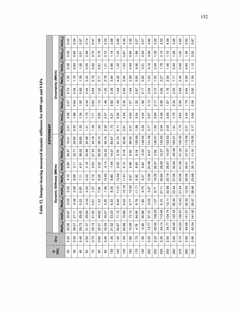
152
Ta
ble
52
. D
am
per
-bea
rin
g m
easu
red
dy
na
mic
sti
ffn
esse
s fo
r 6
000
rp
m a
nd
0 k
Pa
EX
PE
RIM
EN
T
Un
cert
ain
ty (
MN
/m)
Im(U
yy)
0.4
5
0.5
4
0.9
7
0.7
4
0.9
7
1.8
8
2.3
9
2.6
8
2.8
6
4.3
6
3.3
5
2.2
7
3.0
7
4.8
5
3.2
2
3.5
3
4.3
9
3.9
5
4.6
5
3.5
0
5.8
7
Re(U
yy)
0.4
5
0.4
5
0.5
1
0.4
8
0.7
0
0.7
5
0.7
2
1.1
8
1.2
4
0.8
7
0.9
4
1.8
6
2.4
0
3.9
9
1.0
9
2.1
0
1.7
2
1.5
6
1.6
2
1.4
5
2.0
2
Im(U
yx)
2.2
8
0.8
3
1.2
6
0.5
9
0.6
2
0.8
1
1.2
1
0.9
0
1.2
2
1.5
3
4.6
4
4.0
6
3.3
1
4.1
6
2.0
4
1.7
8
1.4
6
0.9
3
0.6
9
0.8
4
1.1
2
Re(U
yx)
1.5
5
1.1
6
1.3
9
0.4
2
0.7
6
0.7
1
2.7
8
3.4
0
4.2
2
2.6
5
2.2
9
0.8
3
2.6
5
1.6
3
1.5
5
2.2
7
2.0
0
1.1
7
2.4
0
2.5
9
1.5
9
Im(U
xy)
0.7
3
0.3
4
0.9
5
0.4
4
0.6
4
1.3
2
1.3
5
2.3
9
1.6
4
0.9
5
1.6
4
2.6
7
2.1
7
3.5
6
2.7
2
2.0
6
1.7
8
3.5
3
3.6
9
2.8
4
3.9
3
Re(U
xy)
0.5
7
0.6
4
1.0
5
0.4
4
0.6
2
1.1
2
1.4
8
0.8
2
1.4
9
2.3
5
1.5
7
1.5
2
1.9
4
4.1
2
2.1
7
3.0
6
1.8
7
3.3
0
2.5
6
1.7
4
2.5
9
Im(U
xx)
3.9
9
1.9
8
1.3
4
1.1
5
1.7
1
2.8
2
2.4
7
5.2
1
5.2
6
4.9
3
4.0
2
3.0
4
4.2
4
3.6
7
2.8
4
4.4
8
3.9
3
1.7
0
3.6
2
3.4
3
3.6
0
Re(U
xx)
2.0
1
3.4
2
1.3
5
1.4
1
1.3
6
1.6
3
2.9
2
1.7
3
6.1
1
2.6
1
3.3
1
1.8
8
3.3
3
3.7
7
1.5
0
2.9
4
2.0
2
1.6
1
1.7
3
2.0
1
2.1
7
Dyn
am
ic S
tiff
ness (
MN
/m)
Im(H
yy)
19.4
1
20.6
2
28.8
5
30.4
8
44.1
9
56.1
5
66.1
6
83.6
7
91.7
4
93.9
5
99.3
3
105.4
9
146.0
4
141.4
8
146.3
7
140.0
0
152.5
3
160.2
1
169.3
5
172.4
9
178.5
5
Re(H
yy)
36.9
7
32.7
1
38.0
2
30.8
6
27.4
3
20.3
5
24.3
2
14.2
1
9.7
6
9.1
8
6.9
0
8.1
8
-0.0
3
8.4
7
3.5
6
12.2
7
-10.9
7
-20.4
8
-21.2
2
-27.5
1
-11.9
1
Im(H
yx)
6.8
0
3.1
1
4.3
1
2.1
8
2.6
3
2.6
2
-0.1
4
-1.4
4
2.5
5
6.1
0
5.9
9
8.9
5
9.6
2
20.4
8
26.9
7
28.9
3
28.6
7
32.6
4
41.5
6
35.4
1
35.1
5
Re(H
yx)
4.1
9
6.0
8
7.1
1
6.2
3
5.1
2
9.2
8
15.6
5
8.8
0
13.5
4
11.6
1
6.8
7
6.9
2
9.3
7
12.9
5
19.3
5
20.8
4
20.1
9
27.0
6
24.0
6
28.0
6
23.6
8
Im(H
xy)
-5.2
2
-3.8
5
0.0
5
-4.4
2
-1.5
7
7.5
6
-1.9
6
-8.3
0
-11.0
1
-15.1
9
-10.5
0
-11.7
1
-9.7
5
-3.2
7
8.7
7
27.1
1
32.0
6
22.4
4
21.5
4
12.0
2
28.4
8
Re(H
xy)
-0.2
3
-2.4
6
0.2
3
-3.4
3
0.5
1
1.4
3
5.3
5
6.3
3
8.4
0
9.0
3
6.7
7
9.7
8
1.9
0
-0.5
2
-1.0
7
6.1
5
13.1
1
26.3
0
13.4
3
33.3
2
26.0
7
Im(H
xx)
20.8
7
27.1
1
29.2
0
29.6
6
41.6
2
48.8
2
45.0
7
53.2
3
71.1
2
70.6
9
73.1
3
84.9
0
90.9
8
97.1
0
108.2
5
113.4
0
124.7
4
133.4
5
130.6
7
141.5
7
141.4
2
Re(H
xx)
35.9
6
36.2
7
29.7
3
31.3
7
25.1
5
30.4
7
33.0
9
21.5
2
20.8
7
20.8
8
15.9
9
4.7
8
-0.4
8
-14.7
7
-20.4
6
-24.1
4
-34.7
7
-48.0
5
-43.2
9
-54.6
8
-43.3
4
Ω/ω
0.2
0
0.3
0
0.4
0
0.5
0
0.7
0
0.8
0
0.9
0
1.3
0
1.4
0
1.5
0
1.6
0
1.7
0
1.9
0
2.0
0
2.2
0
2.3
0
2.5
0
2.6
0
2.7
0
2.8
0
2.9
0
Ω
(Hz)
20
30
40
50
70
80
90
130
140
150
160
170
190
200
220
230
250
260
270
280
290

153
Ta
ble
53
. D
am
per
-bea
rin
g m
easu
red
dy
na
mic
sti
ffn
esse
s fo
r 6
000
rp
m a
nd
17
2 k
Pa
EX
PE
RIM
EN
T
Un
cert
ain
ty (
MN
/m)
Im(U
yy)
0.8
7
0.4
5
0.4
7
0.8
8
0.5
2
0.9
8
0.9
2
2.9
5
4.3
5
1.4
3
1.4
0
1.6
6
2.4
5
1.0
8
1.1
3
1.0
1
1.6
1
4.1
0
11.4
5
6.8
3
Re(U
yy)
0.8
7
0.8
9
0.7
2
0.6
8
0.4
7
2.2
0
0.8
4
3.0
1
2.3
2
1.0
4
1.6
6
2.8
6
1.1
0
1.4
5
2.1
8
4.1
7
1.6
0
5.5
5
6.4
1
3.4
5
Im(U
yx)
1.3
4
0.9
0
0.6
3
0.4
4
0.3
9
1.3
6
0.7
4
2.0
7
2.9
7
0.3
6
0.8
5
1.0
1
1.3
1
0.8
5
1.4
2
2.2
5
3.1
1
2.3
5
5.8
4
3.2
0
Re(U
yx)
1.1
0
0.5
2
0.9
7
0.4
0
0.4
4
0.8
7
0.5
6
2.4
3
2.1
6
0.7
1
1.0
8
0.9
0
1.3
7
0.6
1
1.8
4
2.1
7
2.8
0
2.3
8
4.9
9
4.3
6
Im(U
xy)
0.3
9
0.3
3
0.3
4
0.3
9
0.2
5
0.8
0
0.2
5
2.3
8
3.0
6
1.0
1
0.6
9
0.8
2
0.6
9
0.9
2
1.6
6
1.9
1
2.7
2
5.0
8
10.4
1
6.9
5
Re(U
xy)
0.3
6
0.2
3
0.4
3
0.3
5
0.4
7
0.4
1
0.7
1
3.4
2
4.1
8
0.8
1
0.6
0
0.5
3
1.0
0
0.8
5
1.0
3
2.7
3
3.3
1
2.4
1
2.0
8
3.6
6
Im(U
xx)
1.2
0
0.8
8
1.0
6
0.6
4
1.1
5
0.5
5
0.7
7
2.2
7
2.9
8
1.1
5
1.6
1
1.0
9
1.3
0
0.9
6
1.8
3
1.8
8
2.8
1
1.1
3
6.1
4
6.2
1
Re(U
xx)
1.0
9
0.3
7
0.8
2
1.1
0
0.7
5
0.8
4
0.8
4
2.8
6
3.0
1
1.1
7
0.9
7
1.4
7
0.9
9
1.2
2
1.3
5
2.4
5
3.3
5
1.3
7
2.4
9
3.1
1
Dyn
am
ic S
tiff
ness (
MN
/m)
Im(H
yy)
16.6
7
19.4
7
27.9
2
32.7
1
47.3
7
68.3
1
63.6
2
62.1
4
68.9
1
84.8
4
91.6
3
89.4
7
123.6
7
112.1
1
120.0
3
120.3
8
172.5
4
137.8
7
156.0
7
218.9
4
Re(H
yy)
36.8
5
35.8
6
34.4
7
31.1
7
24.6
5
35.0
3
26.1
9
17.1
6
13.6
7
12.3
1
4.2
0
-11.6
6
11.9
9
0.0
2
-7.0
5
-13.5
4
-20.7
7
-54.4
5
-80.9
3
-49.0
7
Im(H
yx)
3.3
5
0.4
4
2.5
0
0.3
9
0.5
1
2.9
7
1.1
3
-9.5
0
-3.3
3
3.3
7
6.2
1
0.3
7
14.7
1
13.8
2
14.0
6
19.0
6
35.6
9
44.5
6
63.7
6
63.2
2
Re(H
yx)
2.5
6
2.9
3
5.1
3
5.4
3
5.6
8
9.1
7
6.9
6
10.5
6
10.3
2
4.7
5
4.2
0
5.5
4
1.5
9
5.6
2
0.0
2
-5.0
0
4.7
4
13.7
2
10.0
7
19.4
8
Im(H
xy)
-5.2
6
-3.9
9
-3.4
8
-3.7
6
-2.8
8
-3.7
5
-3.3
1
4.1
8
1.3
4
-4.9
2
-6.6
8
-3.4
4
-10.1
7
-7.5
2
-10.4
6
-9.0
6
-7.7
6
1.2
1
13.3
9
22.5
2
Re(H
xy)
-2.4
3
-3.0
0
-3.6
4
-3.7
5
-1.5
0
0.6
6
1.1
5
-5.7
0
-2.8
7
6.6
3
8.4
7
7.3
3
11.6
6
8.9
7
8.0
1
5.7
2
-0.4
5
-21.2
7
-25.5
1
-16.8
8
Im(H
xx)
23.8
8
22.2
3
26.0
5
28.3
9
42.1
1
45.2
3
53.0
8
52.8
2
59.8
4
75.9
1
82.5
7
86.4
7
96.7
4
100.2
3
110.8
2
112.9
7
125.3
1
133.5
0
135.8
2
127.2
9
Re(H
xx)
30.7
4
29.8
6
30.2
9
29.9
5
23.9
1
25.5
8
21.3
0
12.7
8
14.5
2
18.3
3
15.5
3
10.7
0
8.9
1
1.3
6
-4.1
3
-7.5
3
-9.8
4
-20.4
2
-40.3
7
-48.1
9
Ω/ω
0.2
0
0.3
0
0.4
0
0.5
0
0.7
0
0.8
0
0.9
0
1.0
0
1.1
0
1.3
0
1.4
0
1.5
0
1.6
0
1.7
0
1.9
0
2.0
0
2.3
0
2.5
0
2.6
0
2.8
0
Ω
(Hz)
20
30
40
50
70
80
90
100
110
130
140
150
160
170
190
200
230
250
260
280
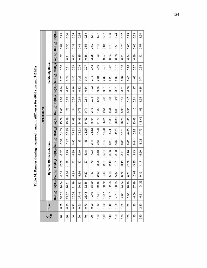
154
Ta
ble
54
. D
am
per
-bea
rin
g m
easu
red
dy
na
mic
sti
ffn
esse
s fo
r 6
000
rp
m a
nd
34
5 k
Pa
EX
PE
RIM
EN
T
Un
cert
ain
ty (
MN
/m)
Im(U
yy)
0.7
5
0.5
4
0.5
5
0.6
5
0.5
3
1.1
1
1.2
7
0.5
7
0.8
6
0.7
4
0.6
7
0.7
3
0.8
3
1.5
4
Re(U
yy)
0.6
2
0.3
0
0.3
9
0.4
1
0.5
1
2.6
9
1.4
3
0.8
4
0.7
9
0.5
8
0.7
3
0.6
3
0.6
5
0.5
7
Im(U
yx)
1.6
7
0.3
1
0.1
3
0.3
5
0.3
6
2.2
5
1.0
3
0.5
7
0.2
4
0.2
3
0.3
1
0.3
4
0.3
9
1.1
2
Re(U
yx)
0.6
8
0.6
1
0.3
8
0.2
9
0.2
7
0.4
2
0.4
0
0.2
1
0.4
2
0.3
7
0.3
0
0.2
8
0.7
7
0.5
5
Im(U
xy)
0.2
5
0.2
4
0.2
0
0.2
8
0.3
4
2.1
3
0.8
1
0.3
2
0.2
6
0.3
2
0.3
7
0.4
0
1.6
8
0.7
4
Re(U
xy)
0.2
4
0.1
7
0.1
6
0.3
3
0.3
4
1.0
2
0.7
6
0.3
1
0.3
1
0.3
1
0.3
1
0.3
6
1.1
7
0.3
8
Im(U
xx)
2.0
6
0.7
5
0.5
5
0.6
4
0.6
1
0.7
4
1.4
2
0.3
2
0.3
3
0.2
9
0.3
1
0.4
7
0.8
1
1.3
5
Re(U
xx)
2.4
6
1.2
3
1.2
4
0.7
8
0.7
1
2.7
3
1.2
0
0.6
1
0.4
4
0.6
0
0.3
6
0.3
8
1.1
0
1.0
3
Dyn
am
ic S
tiff
ness (
MN
/m)
Im(H
yy)
13.2
9
15.5
9
21.6
8
24.9
9
34.6
2
46.0
4
54.7
0
65.2
4
71.3
6
70.3
6
90.7
0
81.8
6
93.8
8
118.4
6
Re(H
yy)
31.6
5
30.9
9
29.8
2
28.6
3
23.2
5
23.6
2
17.2
8
11.7
9
4.7
4
-2.7
9
16.5
1
-0.0
5
0.9
2
-7.7
3
Im(H
yx)
-0.5
6
-0.4
2
0.9
5
1.3
7
1.8
6
2.1
1
3.6
6
4.1
6
6.2
9
5.6
2
6.8
8
9.6
3
9.8
4
18.2
8
Re(H
yx)
6.6
2
2.7
5
4.3
9
5.1
9
5.4
8
7.2
3
8.1
8
6.5
4
8.5
6
8.0
6
6.2
1
8.2
6
9.1
3
6.9
0
Im(H
xy)
-2.8
0
-1.9
2
-1.7
3
-1.3
3
-1.2
7
-1.7
0
-3.0
5
-2.3
4
-2.4
9
-1.7
1
-3.4
3
-2.6
9
-3.9
5
1.1
7
Re(H
xy)
-2.5
5
-1.6
0
-1.9
3
-1.8
6
0.2
7
1.4
7
2.9
2
4.8
3
5.1
6
5.3
7
8.7
2
6.7
1
10.6
2
9.1
3
Im(H
xx)
14.0
4
16.0
1
21.2
9
20.2
3
32.5
6
38.9
9
50.4
6
59.7
0
62.5
5
68.6
5
74.2
4
78.2
0
87.4
9
104.2
3
Re(H
xx)
32.6
5
27.3
7
25.5
4
27.4
6
23.4
3
19.4
9
17.6
1
13.1
7
11.3
7
7.7
2
4.0
6
0.9
3
-4.0
6
-6.6
1
Ω/ω
0.2
0
0.3
0
0.4
0
0.5
0
0.7
0
0.9
0
1.1
0
1.3
0
1.4
0
1.5
0
1.6
0
1.7
0
1.9
0
2.3
0
Ω
(Hz)
20
30
40
50
70
90
110
130
140
150
160
170
190
230
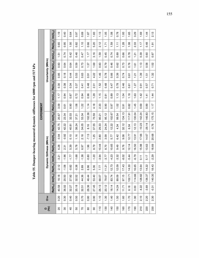
155
Ta
ble
55
. D
am
per
-bea
rin
g m
easu
red
dy
na
mic
sti
ffn
esse
s fo
r 6
000
rp
m a
nd
51
7 k
Pa
EX
PE
RIM
EN
T
Un
cert
ain
ty (
MN
/m)
Im(U
yy)
1.1
9
0.4
0
0.6
4
0.9
7
0.6
9
1.8
7
1.8
3
1.1
3
1.0
5
1.0
8
0.7
8
1.9
3
1.6
5
3.2
9
1.6
9
1.4
4
2.1
3
Re(U
yy)
0.6
5
0.9
5
1.0
0
0.8
2
1.1
0
0.6
6
5.2
0
2.1
2
1.7
1
1.5
9
1.1
1
1.2
8
1.0
8
2.3
3
1.1
7
0.4
8
1.9
1
Im(U
yx)
1.5
1
0.7
4
0.4
2
0.4
8
0.4
7
1.1
7
3.1
6
1.5
9
0.4
5
0.7
4
0.8
9
0.6
6
0.7
8
1.2
1
0.3
9
0.6
0
0.9
7
Re(U
yx)
0.8
3
0.6
4
0.6
4
0.5
9
0.7
3
1.3
7
1.6
9
0.8
3
0.7
9
0.4
6
0.6
2
0.7
3
0.7
6
1.6
1
1.1
3
0.5
8
1.0
2
Im(U
xy)
0.8
5
0.1
8
0.4
4
0.5
3
0.6
3
0.9
1
4.2
2
1.4
6
0.7
8
0.6
6
0.3
9
0.7
4
0.6
1
1.2
1
1.3
9
1.5
1
1.3
2
Re(U
xy)
0.3
0
0.3
8
0.3
4
0.3
7
0.4
1
0.4
8
2.0
1
1.5
2
0.4
8
0.4
7
0.7
8
0.4
6
0.6
1
1.2
7
0.9
1
0.5
7
0.7
1
Im(U
xx)
1.1
7
0.9
4
0.8
7
0.7
2
0.9
4
0.9
6
1.2
9
1.1
5
0.9
1
0.8
9
1.1
3
1.0
4
1.1
8
1.6
3
1.4
2
1.4
1
1.4
4
Re(U
xx)
3.0
9
0.6
1
0.9
0
1.0
8
1.2
2
1.1
4
4.1
8
2.3
3
0.9
0
0.9
7
1.0
2
0.9
1
0.8
2
1.4
5
0.6
9
0.8
9
1.1
7
Dyn
am
ic S
tiff
ness (
MN
/m)
Im(H
yy)
20.6
7
23.3
4
32.0
3
37.2
1
53.3
4
102.3
6
70.5
9
80.2
1
95.1
2
102.6
7
99.5
4
134.1
3
117.9
1
130.0
4
142.2
4
146.8
3
175.1
5
Re(H
yy)
42.7
5
42.2
2
40.8
1
38.2
4
34.0
5
8.1
6
37.5
5
29.3
3
24.2
4
12.2
2
4.3
4
32.1
2
6.3
4
12.1
3
-10.2
3
-29.1
4
-0.7
6
Im(H
yx)
-0.9
4
-0.9
2
0.1
0
1.1
6
2.1
8
-7.1
3
1.2
5
2.8
0
3.0
9
5.7
7
6.4
2
9.0
8
12.7
7
13.9
1
17.6
6
14.6
7
20.6
8
Re(H
yx)
6.2
8
2.3
1
5.3
9
5.7
8
6.9
7
1.9
6
8.7
9
10.4
4
8.7
0
10.6
5
9.4
9
9.7
6
12.1
4
16.5
0
15.9
8
13.6
3
18.6
9
Im(H
xy)
-3.2
1
-1.9
6
-1.7
7
-1.6
8
-1.3
8
-0.8
0
-1.2
0
-3.9
4
-3.7
7
-4.2
3
-3.3
2
-8.0
2
-5.4
4
-6.7
9
0.1
1
5.1
7
-2.2
9
Re(H
xy)
-2.1
2
-1.0
8
-0.8
2
-0.3
8
2.8
9
6.9
6
5.3
6
7.7
7
11.2
1
12.7
3
12.0
9
17.4
3
14.3
0
16.6
5
13.6
4
14.2
2
18.4
3
Im(H
xx)
18.1
8
20.5
0
27.9
2
32.5
2
44.3
6
46.4
4
53.4
0
68.0
7
79.6
7
83.7
4
89.0
9
97.1
5
102.7
1
114.6
6
128.8
2
136.3
7
140.3
0
Re(H
xx)
40.5
8
36.0
2
32.2
7
35.1
8
32.5
1
28.3
6
27.4
5
26.1
3
20.1
2
18.1
4
14.2
4
11.7
1
6.1
8
0.0
0
-4.2
2
-3.6
9
-0.3
1
Ω/ω
0.2
0
0.3
0
0.4
0
0.5
0
0.7
0
0.8
0
0.9
0
1.1
0
1.3
0
1.4
0
1.5
0
1.6
0
1.7
0
1.9
0
2.1
0
2.2
0
2.3
0
Ω
(Hz)
20
30
40
50
70
80
90
110
130
140
150
160
170
190
210
220
230
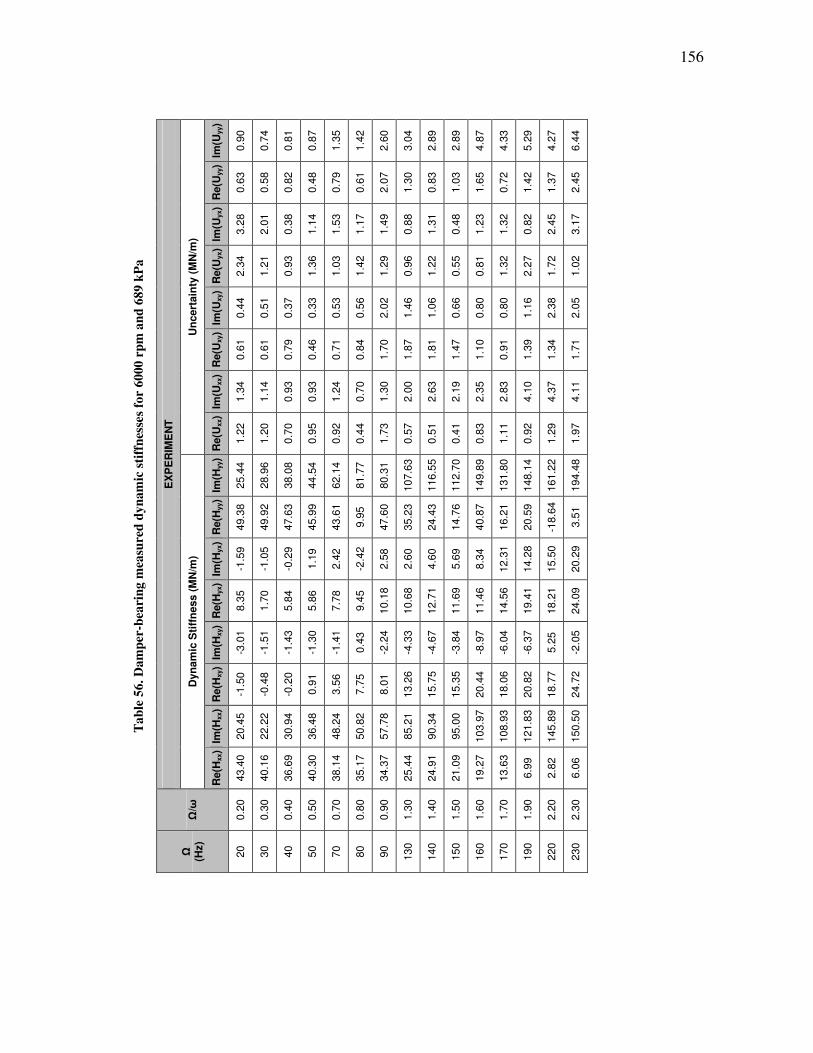
156
Ta
ble
56
. D
am
per
-bea
rin
g m
easu
red
dy
na
mic
sti
ffn
esse
s fo
r 6
000
rp
m a
nd
68
9 k
Pa
EX
PE
RIM
EN
T
Un
cert
ain
ty (
MN
/m)
Im(U
yy)
0.9
0
0.7
4
0.8
1
0.8
7
1.3
5
1.4
2
2.6
0
3.0
4
2.8
9
2.8
9
4.8
7
4.3
3
5.2
9
4.2
7
6.4
4
Re(U
yy)
0.6
3
0.5
8
0.8
2
0.4
8
0.7
9
0.6
1
2.0
7
1.3
0
0.8
3
1.0
3
1.6
5
0.7
2
1.4
2
1.3
7
2.4
5
Im(U
yx)
3.2
8
2.0
1
0.3
8
1.1
4
1.5
3
1.1
7
1.4
9
0.8
8
1.3
1
0.4
8
1.2
3
1.3
2
0.8
2
2.4
5
3.1
7
Re(U
yx)
2.3
4
1.2
1
0.9
3
1.3
6
1.0
3
1.4
2
1.2
9
0.9
6
1.2
2
0.5
5
0.8
1
1.3
2
2.2
7
1.7
2
1.0
2
Im(U
xy)
0.4
4
0.5
1
0.3
7
0.3
3
0.5
3
0.5
6
2.0
2
1.4
6
1.0
6
0.6
6
0.8
0
0.8
0
1.1
6
2.3
8
2.0
5
Re(U
xy)
0.6
1
0.6
1
0.7
9
0.4
6
0.7
1
0.8
4
1.7
0
1.8
7
1.8
1
1.4
7
1.1
0
0.9
1
1.3
9
1.3
4
1.7
1
Im(U
xx)
1.3
4
1.1
4
0.9
3
0.9
3
1.2
4
0.7
0
1.3
0
2.0
0
2.6
3
2.1
9
2.3
5
2.8
3
4.1
0
4.3
7
4.1
1
Re(U
xx)
1.2
2
1.2
0
0.7
0
0.9
5
0.9
2
0.4
4
1.7
3
0.5
7
0.5
1
0.4
1
0.8
3
1.1
1
0.9
2
1.2
9
1.9
7
Dyn
am
ic S
tiff
ness (
MN
/m)
Im(H
yy)
25.4
4
28.9
6
38.0
8
44.5
4
62.1
4
81.7
7
80.3
1
107.6
3
116.5
5
112.7
0
149.8
9
131.8
0
148.1
4
161.2
2
194.4
8
Re(H
yy)
49.3
8
49.9
2
47.6
3
45.9
9
43.6
1
9.9
5
47.6
0
35.2
3
24.4
3
14.7
6
40.8
7
16.2
1
20.5
9
-18.6
4
3.5
1
Im(H
yx)
-1.5
9
-1.0
5
-0.2
9
1.1
9
2.4
2
-2.4
2
2.5
8
2.6
0
4.6
0
5.6
9
8.3
4
12.3
1
14.2
8
15.5
0
20.2
9
Re(H
yx)
8.3
5
1.7
0
5.8
4
5.8
6
7.7
8
9.4
5
10.1
8
10.6
8
12.7
1
11.6
9
11.4
6
14.5
6
19.4
1
18.2
1
24.0
9
Im(H
xy)
-3.0
1
-1.5
1
-1.4
3
-1.3
0
-1.4
1
0.4
3
-2.2
4
-4.3
3
-4.6
7
-3.8
4
-8.9
7
-6.0
4
-6.3
7
5.2
5
-2.0
5
Re(H
xy)
-1.5
0
-0.4
8
-0.2
0
0.9
1
3.5
6
7.7
5
8.0
1
13.2
6
15.7
5
15.3
5
20.4
4
18.0
6
20.8
2
18.7
7
24.7
2
Im(H
xx)
20.4
5
22.2
2
30.9
4
36.4
8
48.2
4
50.8
2
57.7
8
85.2
1
90.3
4
95.0
0
103.9
7
108.9
3
121.8
3
145.8
9
150.5
0
Re(H
xx)
43.4
0
40.1
6
36.6
9
40.3
0
38.1
4
35.1
7
34.3
7
25.4
4
24.9
1
21.0
9
19.2
7
13.6
3
6.9
9
2.8
2
6.0
6
Ω/ω
0.2
0
0.3
0
0.4
0
0.5
0
0.7
0
0.8
0
0.9
0
1.3
0
1.4
0
1.5
0
1.6
0
1.7
0
1.9
0
2.2
0
2.3
0
Ω
(Hz)
20
30
40
50
70
80
90
130
140
150
160
170
190
220
230
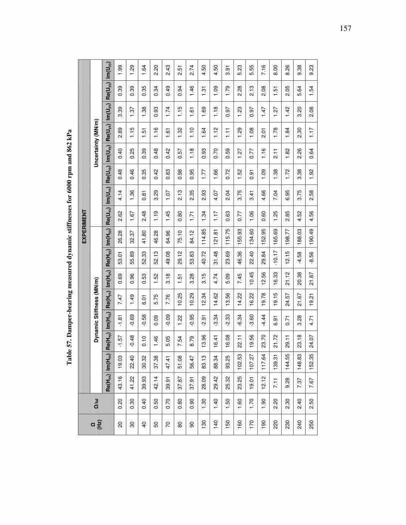
157
Ta
ble
57
. D
am
per
-bea
rin
g m
easu
red
dy
na
mic
sti
ffn
esse
s fo
r 6
000
rp
m a
nd
86
2 k
Pa
EX
PE
RIM
EN
T
Un
cert
ain
ty (
MN
/m)
Im(U
yy)
1.9
9
1.2
9
1.6
4
2.2
0
2.4
3
2.5
1
2.7
4
4.5
0
4.5
0
3.9
1
5.2
3
5.5
5
7.1
6
8.0
0
8.2
6
9.3
8
9.2
3
Re(U
yy)
0.3
9
0.3
9
0.3
5
0.3
4
0.4
9
0.9
4
1.4
6
1.3
1
1.0
9
1.7
9
2.2
8
2.1
3
2.0
8
1.5
1
2.0
5
5.6
4
1.5
4
Im(U
yx)
3.3
9
1.3
7
1.3
8
0.9
3
1.7
4
1.1
5
1.6
1
1.6
9
1.1
8
0.9
7
1.2
3
0.9
7
1.4
7
1.2
7
1.4
2
3.2
0
2.0
8
Re(U
yx)
2.8
9
1.1
5
1.5
1
1.1
6
1.6
1
1.3
2
1.1
0
1.6
4
1.1
2
1.1
1
1.2
9
1.0
8
2.0
1
1.7
8
1.8
4
2.3
0
1.1
7
Im(U
xy)
0.4
0
0.2
5
0.3
9
0.4
8
0.4
2
0.5
7
1.1
8
0.9
3
0.7
0
0.5
9
1.2
7
0.7
7
1.1
6
2.1
1
1.8
2
2.2
6
0.6
4
Re(U
xy)
0.4
8
0.4
6
0.3
5
0.4
2
0.8
3
0.9
8
0.9
5
1.7
7
1.6
6
0.7
2
1.5
2
0.9
1
1.0
9
1.3
8
1.7
2
3.3
8
1.9
2
Im(U
xx)
4.1
4
1.3
6
0.8
1
3.2
9
1.0
7
2.1
3
2.3
5
2.9
3
4.0
7
2.0
4
3.7
5
3.4
1
4.6
6
7.0
4
6.9
5
3.7
5
2.5
8
Re(U
xx)
2.6
2
1.6
7
2.4
8
1.1
9
1.4
5
0.8
0
1.7
1
1.3
4
1.1
7
0.6
3
0.7
7
1.0
6
0.6
0
1.2
5
2.8
5
4.5
2
4.5
6
Dyn
am
ic S
tiff
ness (
MN
/m)
Im(H
yy)
26.2
8
32.3
7
41.8
0
46.2
8
64.9
6
75.1
0
84.1
2
114.8
5
121.8
1
115.7
5
155.9
3
134.6
0
152.9
5
165.6
9
198.7
7
188.0
3
190.4
9
Re(H
yy)
53.0
1
55.8
9
52.3
3
52.1
3
49.0
8
29.1
2
53.8
3
40.7
2
31.4
8
23.6
9
46.3
6
22.4
0
29.8
4
-10.1
7
12.1
5
-4.5
8
-8.5
6
Im(H
yx)
0.6
9
0.9
6
0.5
3
1.5
2
3.1
8
1.5
1
3.2
8
3.1
5
4.7
4
5.0
9
7.4
5
10.4
5
12.5
6
16.3
3
21.1
2
20.3
8
21.8
7
Re(H
yx)
7.4
7
1.4
9
6.0
1
5.7
5
7.7
6
10.2
5
10.2
9
12.3
4
14.6
2
13.5
6
14.2
2
16.2
2
19.7
8
19.1
5
24.5
7
21.6
7
19.2
1
Im(H
xy)
-1.8
1
-0.6
9
-0.5
8
0.0
9
-0.0
9
1.2
2
-0.9
5
-2.9
1
-3.3
4
-2.3
3
-6.3
4
-3.6
0
-4.4
4
6.9
1
0.7
1
3.2
8
4.7
1
Re(H
xy)
-1.5
7
-0.4
8
0.1
0
1.4
6
5.0
5
7.5
4
8.7
9
13.9
6
16.4
1
16.0
8
22.1
1
19.5
6
23.7
0
21.7
2
29.1
1
23.1
8
24.0
7
Im(H
xx)
19.0
3
22.4
0
30.3
2
37.3
8
47.4
1
51.0
8
56.4
7
83.1
3
88.3
4
93.2
5
102.5
3
107.2
7
117.6
4
139.3
1
144.5
5
148.8
3
152.3
5
Re(H
xx)
43.1
6
41.2
2
39.9
3
42.1
4
39.9
1
37.8
7
37.9
1
28.0
9
29.4
2
25.3
2
23.2
5
19.0
1
12.1
2
7.1
1
9.2
8
7.3
7
7.6
7
Ω/ω
0.2
0
0.3
0
0.4
0
0.5
0
0.7
0
0.8
0
0.9
0
1.3
0
1.4
0
1.5
0
1.6
0
1.7
0
1.9
0
2.2
0
2.3
0
2.4
0
2.5
0
Ω
(Hz)
20
30
40
50
70
80
90
130
140
150
160
170
190
220
230
240
250
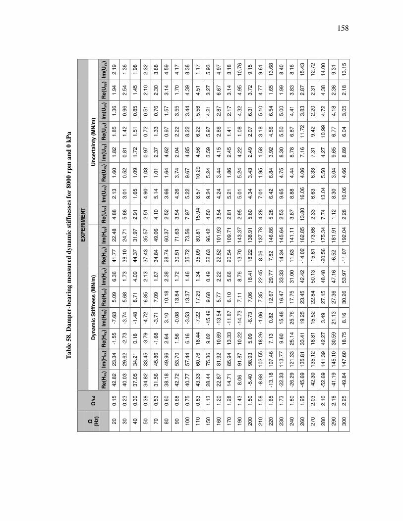
158
Ta
ble
58
. D
am
per
-bea
rin
g m
easu
red
dy
na
mic
sti
ffn
esse
s fo
r 8
000
rp
m a
nd
0 k
Pa
EX
PE
RIM
EN
T
Un
cert
ain
ty (
MN
/m)
Im(U
yy)
2.1
9
1.3
6
1.9
8
2.3
2
3.8
8
4.5
9
4.1
7
8.3
8
1.1
7
5.9
3
4.9
7
3.1
8
10.7
6
9.1
5
9.6
1
13.6
8
8.4
0
8.1
6
15.4
3
12.7
2
14.0
0
9.3
1
13.1
5
Re(U
yy)
1.9
4
2.5
4
1.4
5
2.1
0
2.3
0
3.1
4
1.7
0
4.3
9
4.5
1
3.2
7
6.6
7
3.1
4
4.9
5
3.7
2
4.7
7
1.6
5
1.9
9
3.8
3
2.8
7
2.3
1
4.3
8
2.3
6
2.1
8
Im(U
yx)
1.3
6
0.9
6
0.8
5
0.5
1
0.7
6
1.5
7
3.5
5
3.4
4
5.5
6
4.2
1
2.8
7
2.1
7
4.3
2
6.3
1
5.1
0
6.5
4
5.0
0
4.4
1
3.8
3
2.2
0
4.7
2
4.1
8
3.0
5
Re(U
yx)
1.8
5
1.4
2
1.5
1
0.7
2
1.3
3
0.9
7
2.2
2
8.2
2
6.2
2
5.9
7
2.8
6
1.4
1
1.0
8
2.0
7
3.1
8
4.5
6
5.5
0
6.8
7
11.7
2
9.4
2
10.9
9
6.7
7
6.0
4
Im(U
xy)
1.8
2
0.8
1
1.7
2
0.9
7
2.3
7
4.6
2
2.0
4
4.8
5
4.5
6
3.5
9
4.1
5
2.4
5
4.2
2
2.4
9
1.5
8
3.9
2
8.3
0
8.7
8
7.1
6
7.3
1
4.2
7
9.6
5
8.8
9
Re(U
xy)
1.6
0
0.5
2
1.0
9
1.0
3
1.0
1
1.6
4
3.7
4
9.6
7
10.2
9
5.2
4
3.4
4
1.8
6
5.2
4
3.4
3
1.9
5
6.8
4
4.7
5
4.4
4
4.0
6
6.3
3
5.5
0
3.0
4
4.6
6
Im(U
xx)
2.1
3
3.0
1
1.6
5
4.9
0
5.1
4
3.6
6
4.2
6
5.2
2
8.5
7
9.2
4
4.2
4
5.2
1
5.0
1
4.3
4
7.0
1
6.4
2
9.6
5
8.8
8
16.0
6
6.6
3
13.0
4
8.3
0
10.0
6
Re(U
xx)
4.8
8
5.8
6
2.9
1
2.5
1
4.1
0
2.5
2
3.5
4
7.9
7
15.9
4
4.5
0
3.5
4
2.8
1
2.9
5
5.6
0
4.2
8
5.2
8
2.5
3
3.8
7
13.8
0
2.3
3
7.7
4
1.1
2
2.2
8
Dyn
am
ic S
tiff
ness (
MN
/m)
Im(H
yy)
22.4
8
24.7
1
31.9
7
35.5
7
49.0
6
60.3
7
71.6
3
73.5
6
80.8
1
96.4
2
101.9
3
109.7
1
143.3
7
138.9
1
137.7
8
146.8
6
145.6
4
141.1
1
162.8
5
173.6
6
175.3
4
181.9
1
192.0
4
Re(H
yy)
41.7
7
38.1
0
44.3
7
37.4
3
34.8
4
28.7
4
30.5
1
35.7
2
35.0
9
22.6
3
22.5
2
20.5
4
13.7
0
18.2
2
8.0
6
7.8
2
14.3
4
11.6
3
-14.0
2
-15.6
1
-20.5
6
-6.5
2
-11.0
7
Im(H
yx)
6.3
6
1.7
3
4.0
9
2.1
3
1.6
7
2.3
8
1.7
2
1.4
6
1.3
4
0.4
9
2.2
2
5.6
6
8.7
6
18.4
1
22.4
5
29.7
7
33.3
3
31.0
0
42.4
2
50.1
3
48.4
8
47.1
6
53.9
7
Re(H
yx)
5.0
9
5.6
8
8.7
1
6.8
5
7.0
9
10.1
8
13.8
4
13.3
7
17.2
9
9.6
8
5.7
7
6.1
0
7.1
1
7.0
6
7.3
5
12.6
7
16.4
7
17.7
5
23.4
5
22.8
4
27.1
5
27.3
6
30.2
6
Im(H
xy)
-7.6
3
-3.7
4
-1.4
8
-4.7
2
-3.7
1
3.1
0
-0.0
8
-3.5
3
-7.2
2
-15.4
9
-13.5
4
-11.8
7
-14.7
3
-6.7
3
-1.0
6
0.8
2
15.4
8
25.7
6
19.2
5
15.5
2
3.4
9
21.1
3
8.1
6
Re(H
xy)
-1.5
5
-2.7
3
0.1
8
-3.7
9
-1.6
8
2.6
4
1.5
6
6.1
6
18.4
4
9.0
2
10.6
9
13.3
3
10.2
2
5.0
9
18.2
6
7.1
3
9.6
0
25.1
4
33.4
1
18.8
1
42.2
7
30.5
9
18.7
5
Im(H
xx)
23.3
4
29.6
2
34.2
1
33.4
5
45.8
6
49.9
6
53.7
0
57.4
4
60.7
6
75.3
6
81.9
2
85.9
4
91.8
7
98.9
3
102.5
5
107.4
6
113.7
7
121.3
3
135.8
1
135.1
2
141.3
9
145.1
0
147.6
0
Re(H
xx)
42.8
2
40.0
3
37.0
5
34.8
2
31.5
6
38.1
8
42.7
2
40.7
7
43.3
3
28.4
4
22.8
7
14.7
1
8.0
6
-5.4
0
-8.6
8
-13.1
8
-22.3
3
-26.2
9
-45.6
9
-42.3
0
-52.6
9
-41.1
9
-49.8
4
Ω/ω
0.1
5
0.2
3
0.3
0
0.3
8
0.5
3
0.6
0
0.6
8
0.7
5
0.8
3
1.1
3
1.2
0
1.2
8
1.4
3
1.5
0
1.5
8
1.6
5
1.7
3
1.8
0
1.9
5
2.0
3
2.1
0
2.1
8
2.2
5
Ω
(Hz)
20
30
40
50
70
80
90
100
110
150
160
170
190
200
210
220
230
240
260
270
280
290
300
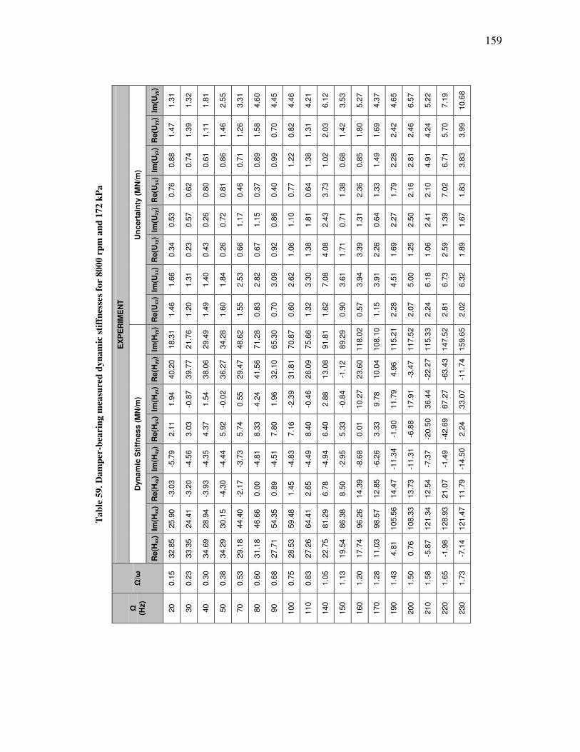
159
Ta
ble
59
. D
am
per
-bea
rin
g m
easu
red
dy
na
mic
sti
ffn
esse
s fo
r 8
000
rp
m a
nd
17
2 k
Pa
EX
PE
RIM
EN
T
Un
cert
ain
ty (
MN
/m)
Im(U
yy)
1.3
1
1.3
2
1.8
1
2.5
5
3.3
1
4.6
0
4.4
5
4.4
6
4.2
1
6.1
2
3.5
3
5.2
7
4.3
7
4.6
5
6.5
7
5.2
2
7.1
9
10.6
8
Re(U
yy)
1.4
7
1.3
9
1.1
1
1.4
6
1.2
6
1.5
8
0.7
0
0.8
2
1.3
1
2.0
3
1.4
2
1.8
0
1.6
9
2.4
2
2.4
6
4.2
4
5.7
0
3.9
9
Im(U
yx)
0.8
8
0.7
4
0.6
1
0.8
6
0.7
1
0.8
9
0.9
9
1.2
2
1.3
8
1.0
2
0.6
8
0.8
5
1.4
9
2.2
8
2.8
1
4.9
1
6.7
1
3.8
3
Re(U
yx)
0.7
6
0.6
2
0.8
0
0.8
1
0.4
6
0.3
7
0.4
0
0.7
7
0.6
4
3.7
3
1.3
8
2.3
6
1.3
3
1.7
9
2.1
6
2.1
0
7.0
2
1.8
3
Im(U
xy)
0.5
3
0.5
7
0.2
6
0.7
2
1.1
7
1.1
5
0.8
6
1.1
0
1.8
1
2.4
3
0.7
1
1.3
1
0.6
4
2.2
7
2.5
0
2.4
1
1.3
9
1.6
7
Re(U
xy)
0.3
4
0.2
3
0.4
3
0.2
6
0.6
6
0.6
7
0.9
2
1.0
6
1.3
8
4.0
8
1.7
1
3.3
9
2.2
6
1.6
9
1.2
5
1.0
6
2.5
9
1.8
9
Im(U
xx)
1.6
6
1.3
1
1.4
0
1.8
4
2.5
3
2.8
2
3.0
9
2.6
2
3.3
0
7.0
8
3.6
1
3.9
4
3.9
1
4.5
1
5.0
0
6.1
8
6.7
3
6.3
2
Re(U
xx)
1.4
6
1.2
0
1.4
9
1.6
0
1.5
5
0.8
3
0.7
0
0.6
0
1.3
2
1.6
2
0.9
0
0.5
7
1.1
5
2.2
8
2.0
7
2.2
4
2.8
1
2.0
2
Dyn
am
ic S
tiff
ness (
MN
/m)
Im(H
yy)
18.3
1
21.7
6
29.4
9
34.2
8
48.6
2
71.2
8
65.3
0
70.8
7
75.6
6
91.8
1
89.2
9
118.0
2
108.1
0
115.2
1
117.5
2
115.3
3
147.5
2
159.6
5
Re(H
yy)
40.2
0
39.7
7
38.0
6
36.2
7
29.4
7
41.5
6
32.1
0
31.8
1
26.0
9
13.0
8
-1.1
2
23.6
0
10.0
4
4.9
6
-3.4
7
-22.2
7
-63.4
3
-11.7
4
Im(H
yx)
1.9
4
-0.8
7
1.5
4
-0.0
2
0.5
5
4.2
4
1.9
6
-2.3
9
-0.4
6
2.8
8
-0.8
4
10.2
7
9.7
8
11.7
9
17.9
1
36.4
4
67.2
7
33.0
7
Re(H
yx)
2.1
1
3.0
3
4.3
7
5.9
2
5.7
4
8.3
3
7.8
0
7.1
6
8.4
0
6.4
0
5.3
3
0.0
1
3.3
3
-1.9
0
-6.8
8
-20.5
0
-42.6
9
2.2
4
Im(H
xy)
-5.7
9
-4.5
6
-4.3
5
-4.4
4
-3.7
3
-4.8
1
-4.5
1
-4.8
3
-4.4
9
-4.9
4
-2.9
5
-8.6
8
-6.2
6
-11.3
4
-11.3
1
-7.3
7
-1.4
9
-14.5
0
Re(H
xy)
-3.0
3
-3.2
0
-3.9
3
-4.3
0
-2.1
7
0.0
0
0.8
9
1.4
5
2.6
5
6.7
8
8.5
0
14.3
9
12.8
5
14.4
7
13.7
3
12.5
4
21.0
7
11.7
9
Im(H
xx)
25.9
0
24.4
1
28.9
4
30.1
5
44.4
0
46.6
6
54.3
5
59.4
8
64.4
1
81.2
9
86.3
8
96.2
6
98.5
7
105.5
6
108.3
3
121.3
4
128.9
3
121.4
7
Re(H
xx)
32.8
5
33.3
5
34.6
9
34.2
9
29.1
8
31.1
8
27.7
1
28.5
3
27.2
6
22.7
5
19.5
4
17.7
4
11.0
3
4.8
1
0.7
6
-5.8
7
-1.9
8
-7.1
4
Ω/ω
0.1
5
0.2
3
0.3
0
0.3
8
0.5
3
0.6
0
0.6
8
0.7
5
0.8
3
1.0
5
1.1
3
1.2
0
1.2
8
1.4
3
1.5
0
1.5
8
1.6
5
1.7
3
Ω
(Hz)
20
30
40
50
70
80
90
100
110
140
150
160
170
190
200
210
220
230
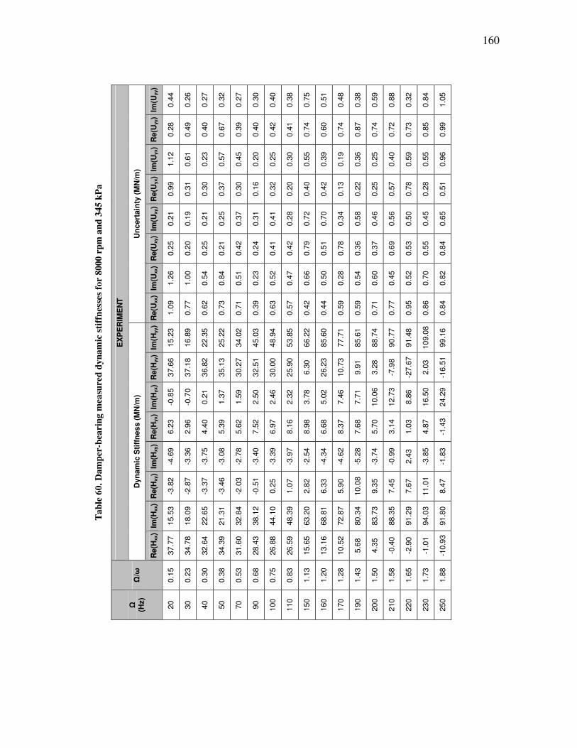
160
Ta
ble
60
. D
am
per
-bea
rin
g m
easu
red
dy
na
mic
sti
ffn
esse
s fo
r 8
000
rp
m a
nd
34
5 k
Pa
EX
PE
RIM
EN
T
Un
cert
ain
ty (
MN
/m)
Im(U
yy)
0.4
4
0.2
6
0.2
7
0.3
2
0.2
7
0.3
0
0.4
0
0.3
8
0.7
5
0.5
1
0.4
8
0.3
8
0.5
9
0.8
8
0.3
2
0.8
4
1.0
5
Re(U
yy)
0.2
8
0.4
9
0.4
0
0.6
7
0.3
9
0.4
0
0.4
2
0.4
1
0.7
4
0.6
0
0.7
4
0.8
7
0.7
4
0.7
2
0.7
3
0.8
5
0.9
9
Im(U
yx)
1.1
2
0.6
1
0.2
3
0.5
7
0.4
5
0.2
0
0.2
5
0.3
0
0.5
5
0.3
9
0.1
9
0.3
6
0.2
5
0.4
0
0.5
9
0.5
5
0.9
6
Re(U
yx)
0.9
9
0.3
1
0.3
0
0.3
7
0.3
0
0.1
6
0.3
2
0.2
0
0.4
0
0.4
2
0.1
3
0.2
2
0.2
5
0.5
7
0.7
8
0.2
8
0.5
1
Im(U
xy)
0.2
1
0.1
9
0.2
1
0.2
5
0.3
7
0.3
1
0.4
1
0.2
8
0.7
2
0.7
0
0.3
4
0.5
8
0.4
6
0.5
6
0.5
0
0.4
5
0.6
5
Re(U
xy)
0.2
5
0.2
0
0.2
5
0.2
1
0.4
2
0.2
4
0.4
1
0.4
2
0.7
9
0.5
1
0.7
8
0.3
6
0.3
7
0.6
9
0.5
3
0.5
5
0.8
4
Im(U
xx)
1.2
6
1.0
0
0.5
4
0.8
4
0.5
1
0.2
3
0.5
2
0.4
7
0.6
6
0.5
0
0.2
8
0.5
4
0.6
0
0.4
5
0.5
2
0.7
0
0.8
2
Re(U
xx)
1.0
9
0.7
7
0.6
2
0.7
3
0.7
1
0.3
9
0.6
3
0.5
7
0.4
2
0.4
4
0.5
9
0.5
9
0.7
1
0.7
7
0.9
5
0.8
6
0.8
4
Dyn
am
ic S
tiff
ness (
MN
/m)
Im(H
yy)
15.2
3
16.8
9
22.3
5
25.2
2
34.0
2
45.0
3
48.9
4
53.8
5
66.2
2
85.6
0
77.7
1
85.6
1
88.7
4
90.7
7
91.4
8
109.0
8
99.1
6
Re(H
yy)
37.6
6
37.1
8
36.8
2
35.1
3
30.2
7
32.5
1
30.0
0
25.9
0
6.3
0
26.2
3
10.7
3
9.9
1
3.2
8
-7.9
8
-27.6
7
2.0
3
-16.5
1
Im(H
yx)
-0.8
5
-0.7
0
0.2
1
1.3
7
1.5
9
2.5
0
2.4
6
2.3
2
3.7
8
5.0
2
7.4
6
7.7
1
10.0
6
12.7
3
8.8
6
16.5
0
24.2
9
Re(H
yx)
6.2
3
2.9
6
4.4
0
5.3
9
5.6
2
7.5
2
6.9
7
8.1
6
8.9
8
6.6
8
8.3
7
7.6
8
5.7
0
3.1
4
1.0
3
4.8
7
-1.4
3
Im(H
xy)
-4.6
9
-3.3
6
-3.7
5
-3.0
8
-2.7
8
-3.4
0
-3.3
9
-3.9
7
-2.5
4
-4.3
4
-4.6
2
-5.2
8
-3.7
4
-0.9
9
2.4
3
-3.8
5
-1.8
3
Re(H
xy)
-3.8
2
-2.8
7
-3.3
7
-3.4
6
-2.0
3
-0.5
1
0.2
5
1.0
7
2.8
2
6.3
3
5.9
0
10.0
8
9.3
5
7.4
5
7.6
7
11.0
1
8.4
7
Im(H
xx)
15.5
3
18.0
9
22.6
5
21.3
1
32.8
4
38.1
2
44.1
0
48.3
9
63.2
0
68.8
1
72.8
7
80.3
4
83.7
3
88.3
5
91.2
9
94.0
3
91.8
0
Re(H
xx)
37.7
7
34.7
8
32.6
4
34.3
9
31.6
0
28.4
3
26.8
8
26.5
9
15.6
5
13.1
6
10.5
2
5.6
8
4.3
5
-0.4
0
-2.9
0
-1.0
1
-10.9
3
Ω/ω
0.1
5
0.2
3
0.3
0
0.3
8
0.5
3
0.6
8
0.7
5
0.8
3
1.1
3
1.2
0
1.2
8
1.4
3
1.5
0
1.5
8
1.6
5
1.7
3
1.8
8
Ω
(Hz)
20
30
40
50
70
90
100
110
150
160
170
190
200
210
220
230
250

161
Ta
ble
61
. D
am
per
-bea
rin
g m
easu
red
dy
na
mic
sti
ffn
esse
s fo
r 8
000
rp
m a
nd
51
7 k
Pa
EX
PE
RIM
EN
T
Un
cert
ain
ty (
MN
/m)
Im(U
yy)
1.4
0
0.3
4
0.3
8
0.6
8
0.8
4
1.0
8
1.0
3
2.1
6
2.4
0
1.7
9
1.6
1
1.9
8
3.1
5
2.3
4
2.6
1
2.3
1
Re(U
yy)
0.9
5
1.2
9
1.1
4
1.4
0
1.3
0
1.1
1
2.2
7
5.2
0
2.6
2
3.6
4
3.5
7
3.5
1
3.5
2
3.9
5
3.9
7
5.0
2
Im(U
yx)
1.2
2
1.0
0
0.5
9
0.8
6
0.6
3
0.4
9
1.0
4
5.7
9
1.0
9
1.2
2
1.6
5
1.6
0
1.5
2
1.6
5
1.1
3
1.0
9
Re(U
yx)
1.0
7
0.7
6
0.7
1
0.8
5
0.4
3
0.8
7
0.5
9
0.5
3
0.9
6
0.8
4
0.4
5
1.1
4
1.8
9
1.9
7
2.3
5
1.0
2
Im(U
xy)
0.5
7
0.3
5
0.4
0
0.6
6
0.5
5
0.4
6
1.1
6
4.1
4
1.6
9
0.8
8
0.8
5
0.8
3
0.7
1
0.9
0
2.0
4
6.3
3
Re(U
xy)
0.2
3
0.2
4
0.4
5
0.5
6
0.7
1
0.5
7
0.6
5
2.2
7
2.5
4
2.6
0
1.1
1
1.4
7
1.7
4
1.6
1
1.4
9
1.1
3
Im(U
xx)
1.5
9
0.8
4
0.4
8
1.3
8
0.8
0
0.9
6
1.2
1
1.8
8
2.2
4
1.1
7
1.1
2
1.8
0
2.0
5
2.5
0
2.3
7
2.2
3
Re(U
xx)
4.1
5
1.5
1
2.0
9
2.8
4
2.5
9
2.5
6
3.5
1
9.5
0
2.8
7
2.6
4
3.2
1
3.5
4
3.5
3
3.3
1
2.1
0
1.4
3
Dyn
am
ic S
tiff
ness (
MN
/m)
Im(H
yy)
21.3
5
23.5
9
30.9
7
36.0
6
50.5
6
67.7
4
74.6
5
77.8
5
96.3
7
123.4
3
106.8
2
114.6
5
123.6
8
124.7
3
130.4
1
152.7
2
Re(H
yy)
44.5
8
43.5
6
42.7
3
40.7
1
35.7
1
41.8
4
37.7
0
33.4
0
11.4
2
40.9
0
17.6
0
23.5
3
13.9
2
-2.8
4
-20.2
4
4.0
0
Im(H
yx)
-1.7
4
-2.2
3
-0.1
8
1.3
7
1.9
1
2.5
8
2.3
4
1.5
4
3.6
5
5.2
2
7.8
7
9.5
6
13.3
2
17.4
4
17.1
8
26.5
4
Re(H
yx)
4.5
4
2.6
4
4.5
2
6.0
0
7.0
3
9.5
6
8.2
5
10.6
5
9.9
6
8.2
1
10.3
9
10.4
8
9.2
8
7.0
7
5.4
9
10.4
2
Im(H
xy)
-4.1
8
-2.9
1
-3.2
4
-2.9
9
-1.9
1
-3.1
7
-3.5
9
-4.1
0
-2.7
6
-7.1
4
-5.2
6
-9.0
1
-7.9
9
-5.2
0
-2.9
2
-9.5
8
Re(H
xy)
-3.3
4
-2.4
6
-2.4
5
-2.6
5
-0.0
1
3.5
8
4.7
8
5.2
9
10.4
9
15.7
3
14.9
6
18.3
0
19.0
4
16.7
7
16.1
8
19.8
5
Im(H
xx)
19.4
1
23.2
8
29.7
2
32.6
5
44.7
0
51.6
7
58.9
7
65.2
6
84.7
7
91.1
9
95.9
1
104.5
7
109.1
4
115.3
4
121.6
0
125.0
2
Re(H
xx)
42.6
3
38.7
9
36.3
7
39.7
6
37.4
4
33.7
7
32.4
7
31.8
8
20.3
3
18.6
4
14.3
8
8.3
1
5.8
5
1.0
7
-0.4
1
0.3
8
Ω/ω
0.1
5
0.2
3
0.3
0
0.3
8
0.5
3
0.6
8
0.7
5
0.8
3
1.1
3
1.2
0
1.2
8
1.4
3
1.5
0
1.5
8
1.6
5
1.7
3
Ω
(Hz)
20
30
40
50
70
90
100
110
150
160
170
190
200
210
220
230
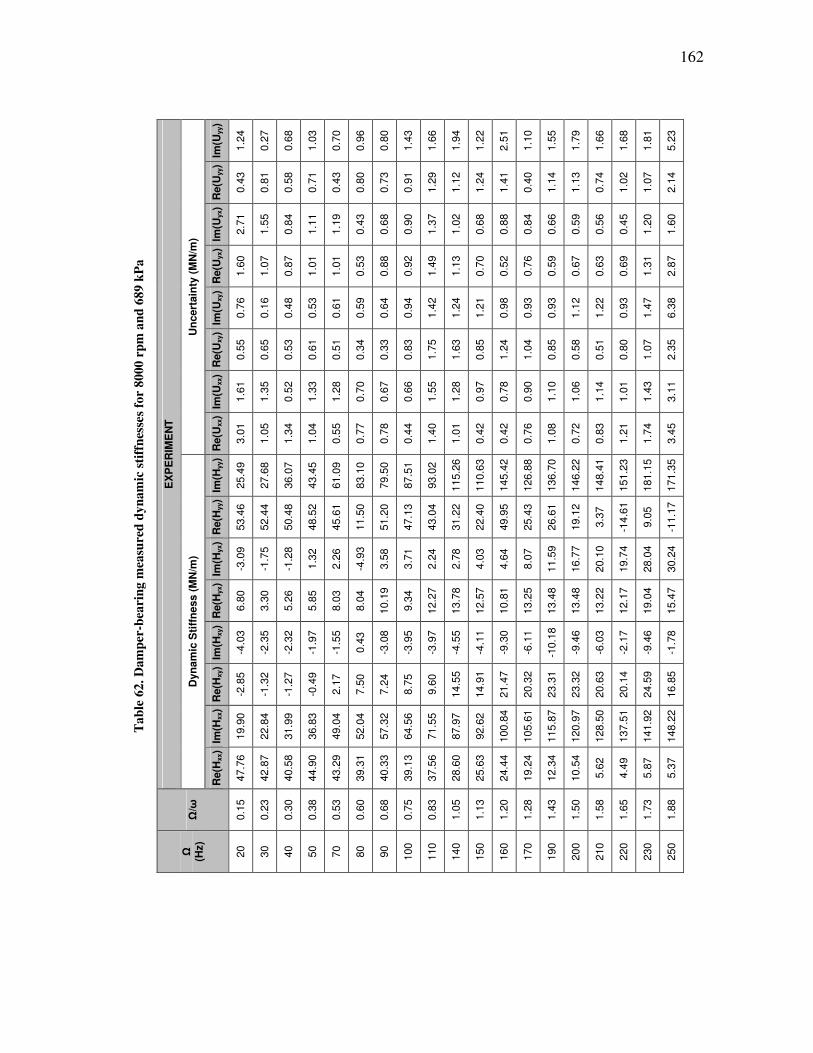
162
Ta
ble
62
. D
am
per
-bea
rin
g m
easu
red
dy
na
mic
sti
ffn
esse
s fo
r 8
000
rp
m a
nd
68
9 k
Pa
EX
PE
RIM
EN
T
Un
cert
ain
ty (
MN
/m)
Im(U
yy)
1.2
4
0.2
7
0.6
8
1.0
3
0.7
0
0.9
6
0.8
0
1.4
3
1.6
6
1.9
4
1.2
2
2.5
1
1.1
0
1.5
5
1.7
9
1.6
6
1.6
8
1.8
1
5.2
3
Re(U
yy)
0.4
3
0.8
1
0.5
8
0.7
1
0.4
3
0.8
0
0.7
3
0.9
1
1.2
9
1.1
2
1.2
4
1.4
1
0.4
0
1.1
4
1.1
3
0.7
4
1.0
2
1.0
7
2.1
4
Im(U
yx)
2.7
1
1.5
5
0.8
4
1.1
1
1.1
9
0.4
3
0.6
8
0.9
0
1.3
7
1.0
2
0.6
8
0.8
8
0.8
4
0.6
6
0.5
9
0.5
6
0.4
5
1.2
0
1.6
0
Re(U
yx)
1.6
0
1.0
7
0.8
7
1.0
1
1.0
1
0.5
3
0.8
8
0.9
2
1.4
9
1.1
3
0.7
0
0.5
2
0.7
6
0.5
9
0.6
7
0.6
3
0.6
9
1.3
1
2.8
7
Im(U
xy)
0.7
6
0.1
6
0.4
8
0.5
3
0.6
1
0.5
9
0.6
4
0.9
4
1.4
2
1.2
4
1.2
1
0.9
8
0.9
3
0.9
3
1.1
2
1.2
2
0.9
3
1.4
7
6.3
8
Re(U
xy)
0.5
5
0.6
5
0.5
3
0.6
1
0.5
1
0.3
4
0.3
3
0.8
3
1.7
5
1.6
3
0.8
5
1.2
4
1.0
4
0.8
5
0.5
8
0.5
1
0.8
0
1.0
7
2.3
5
Im(U
xx)
1.6
1
1.3
5
0.5
2
1.3
3
1.2
8
0.7
0
0.6
7
0.6
6
1.5
5
1.2
8
0.9
7
0.7
8
0.9
0
1.1
0
1.0
6
1.1
4
1.0
1
1.4
3
3.1
1
Re(U
xx)
3.0
1
1.0
5
1.3
4
1.0
4
0.5
5
0.7
7
0.7
8
0.4
4
1.4
0
1.0
1
0.4
2
0.4
2
0.7
6
1.0
8
0.7
2
0.8
3
1.2
1
1.7
4
3.4
5
Dyn
am
ic S
tiff
ness (
MN
/m)
Im(H
yy)
25.4
9
27.6
8
36.0
7
43.4
5
61.0
9
83.1
0
79.5
0
87.5
1
93.0
2
115.2
6
110.6
3
145.4
2
126.8
8
136.7
0
146.2
2
148.4
1
151.2
3
181.1
5
171.3
5
Re(H
yy)
53.4
6
52.4
4
50.4
8
48.5
2
45.6
1
11.5
0
51.2
0
47.1
3
43.0
4
31.2
2
22.4
0
49.9
5
25.4
3
26.6
1
19.1
2
3.3
7
-14.6
1
9.0
5
-11.1
7
Im(H
yx)
-3.0
9
-1.7
5
-1.2
8
1.3
2
2.2
6
-4.9
3
3.5
8
3.7
1
2.2
4
2.7
8
4.0
3
4.6
4
8.0
7
11.5
9
16.7
7
20.1
0
19.7
4
28.0
4
30.2
4
Re(H
yx)
6.8
0
3.3
0
5.2
6
5.8
5
8.0
3
8.0
4
10.1
9
9.3
4
12.2
7
13.7
8
12.5
7
10.8
1
13.2
5
13.4
8
13.4
8
13.2
2
12.1
7
19.0
4
15.4
7
Im(H
xy)
-4.0
3
-2.3
5
-2.3
2
-1.9
7
-1.5
5
0.4
3
-3.0
8
-3.9
5
-3.9
7
-4.5
5
-4.1
1
-9.3
0
-6.1
1
-10.1
8
-9.4
6
-6.0
3
-2.1
7
-9.4
6
-1.7
8
Re(H
xy)
-2.8
5
-1.3
2
-1.2
7
-0.4
9
2.1
7
7.5
0
7.2
4
8.7
5
9.6
0
14.5
5
14.9
1
21.4
7
20.3
2
23.3
1
23.3
2
20.6
3
20.1
4
24.5
9
16.8
5
Im(H
xx)
19.9
0
22.8
4
31.9
9
36.8
3
49.0
4
52.0
4
57.3
2
64.5
6
71.5
5
87.9
7
92.6
2
100.8
4
105.6
1
115.8
7
120.9
7
128.5
0
137.5
1
141.9
2
148.2
2
Re(H
xx)
47.7
6
42.8
7
40.5
8
44.9
0
43.2
9
39.3
1
40.3
3
39.1
3
37.5
6
28.6
0
25.6
3
24.4
4
19.2
4
12.3
4
10.5
4
5.6
2
4.4
9
5.8
7
5.3
7
Ω/ω
0.1
5
0.2
3
0.3
0
0.3
8
0.5
3
0.6
0
0.6
8
0.7
5
0.8
3
1.0
5
1.1
3
1.2
0
1.2
8
1.4
3
1.5
0
1.5
8
1.6
5
1.7
3
1.8
8
Ω
(Hz)
20
30
40
50
70
80
90
100
110
140
150
160
170
190
200
210
220
230
250
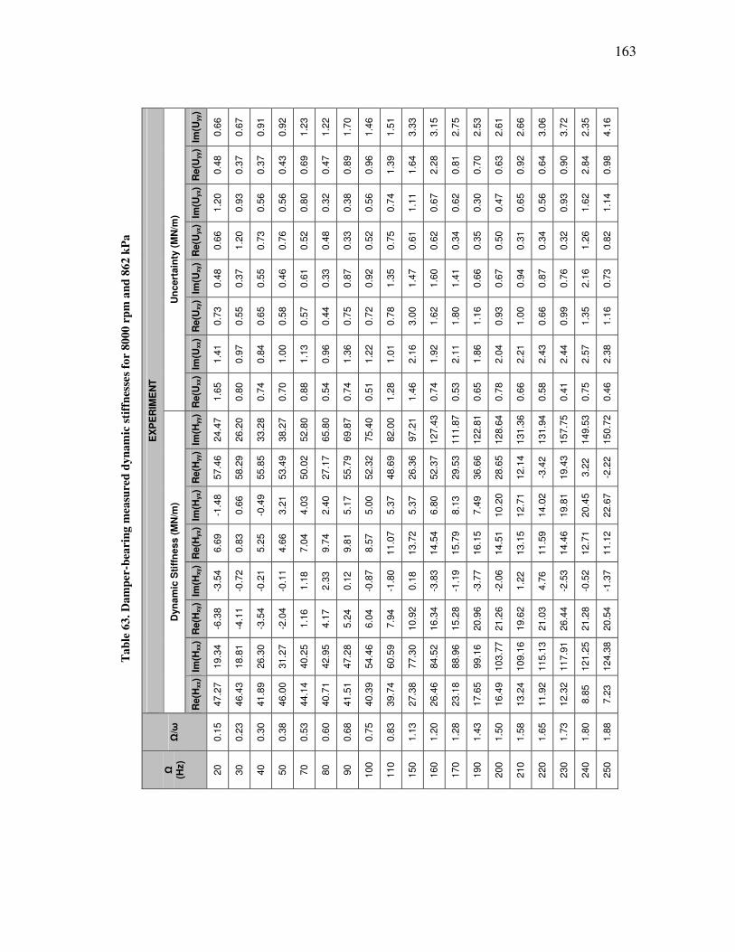
163
Ta
ble
63
. D
am
per
-bea
rin
g m
easu
red
dy
na
mic
sti
ffn
esse
s fo
r 8
000
rp
m a
nd
86
2 k
Pa
EX
PE
RIM
EN
T
Un
cert
ain
ty (
MN
/m)
Im(U
yy)
0.6
6
0.6
7
0.9
1
0.9
2
1.2
3
1.2
2
1.7
0
1.4
6
1.5
1
3.3
3
3.1
5
2.7
5
2.5
3
2.6
1
2.6
6
3.0
6
3.7
2
2.3
5
4.1
6
Re(U
yy)
0.4
8
0.3
7
0.3
7
0.4
3
0.6
9
0.4
7
0.8
9
0.9
6
1.3
9
1.6
4
2.2
8
0.8
1
0.7
0
0.6
3
0.9
2
0.6
4
0.9
0
2.8
4
0.9
8
Im(U
yx)
1.2
0
0.9
3
0.5
6
0.5
6
0.8
0
0.3
2
0.3
8
0.5
6
0.7
4
1.1
1
0.6
7
0.6
2
0.3
0
0.4
7
0.6
5
0.5
6
0.9
3
1.6
2
1.1
4
Re(U
yx)
0.6
6
1.2
0
0.7
3
0.7
6
0.5
2
0.4
8
0.3
3
0.5
2
0.7
5
0.6
1
0.6
2
0.3
4
0.3
5
0.5
0
0.3
1
0.3
4
0.3
2
1.2
6
0.8
2
Im(U
xy)
0.4
8
0.3
7
0.5
5
0.4
6
0.6
1
0.3
3
0.8
7
0.9
2
1.3
5
1.4
7
1.6
0
1.4
1
0.6
6
0.6
7
0.9
4
0.8
7
0.7
6
2.1
6
0.7
3
Re(U
xy)
0.7
3
0.5
5
0.6
5
0.5
8
0.5
7
0.4
4
0.7
5
0.7
2
0.7
8
3.0
0
1.6
2
1.8
0
1.1
6
0.9
3
1.0
0
0.6
6
0.9
9
1.3
5
1.1
6
Im(U
xx)
1.4
1
0.9
7
0.8
4
1.0
0
1.1
3
0.9
6
1.3
6
1.2
2
1.0
1
2.1
6
1.9
2
2.1
1
1.8
6
2.0
4
2.2
1
2.4
3
2.4
4
2.5
7
2.3
8
Re(U
xx)
1.6
5
0.8
0
0.7
4
0.7
0
0.8
8
0.5
4
0.7
4
0.5
1
1.2
8
1.4
6
0.7
4
0.5
3
0.6
5
0.7
8
0.6
6
0.5
8
0.4
1
0.7
5
0.4
6
Dyn
am
ic S
tiff
ness (
MN
/m)
Im(H
yy)
24.4
7
26.2
0
33.2
8
38.2
7
52.8
0
65.8
0
69.8
7
75.4
0
82.0
0
97.2
1
127.4
3
111.8
7
122.8
1
128.6
4
131.3
6
131.9
4
157.7
5
149.5
3
150.7
2
Re(H
yy)
57.4
6
58.2
9
55.8
5
53.4
9
50.0
2
27.1
7
55.7
9
52.3
2
48.6
9
26.3
6
52.3
7
29.5
3
36.6
6
28.6
5
12.1
4
-3.4
2
19.4
3
3.2
2
-2.2
2
Im(H
yx)
-1.4
8
0.6
6
-0.4
9
3.2
1
4.0
3
2.4
0
5.1
7
5.0
0
5.3
7
5.3
7
6.8
0
8.1
3
7.4
9
10.2
0
12.7
1
14.0
2
19.8
1
20.4
5
22.6
7
Re(H
yx)
6.6
9
0.8
3
5.2
5
4.6
6
7.0
4
9.7
4
9.8
1
8.5
7
11.0
7
13.7
2
14.5
4
15.7
9
16.1
5
14.5
1
13.1
5
11.5
9
14.4
6
12.7
1
11.1
2
Im(H
xy)
-3.5
4
-0.7
2
-0.2
1
-0.1
1
1.1
8
2.3
3
0.1
2
-0.8
7
-1.8
0
0.1
8
-3.8
3
-1.1
9
-3.7
7
-2.0
6
1.2
2
4.7
6
-2.5
3
-0.5
2
-1.3
7
Re(H
xy)
-6.3
8
-4.1
1
-3.5
4
-2.0
4
1.1
6
4.1
7
5.2
4
6.0
4
7.9
4
10.9
2
16.3
4
15.2
8
20.9
6
21.2
6
19.6
2
21.0
3
26.4
4
21.2
8
20.5
4
Im(H
xx)
19.3
4
18.8
1
26.3
0
31.2
7
40.2
5
42.9
5
47.2
8
54.4
6
60.5
9
77.3
0
84.5
2
88.9
6
99.1
6
103.7
7
109.1
6
115.1
3
117.9
1
121.2
5
124.3
8
Re(H
xx)
47.2
7
46.4
3
41.8
9
46.0
0
44.1
4
40.7
1
41.5
1
40.3
9
39.7
4
27.3
8
26.4
6
23.1
8
17.6
5
16.4
9
13.2
4
11.9
2
12.3
2
8.8
5
7.2
3
Ω/ω
0.1
5
0.2
3
0.3
0
0.3
8
0.5
3
0.6
0
0.6
8
0.7
5
0.8
3
1.1
3
1.2
0
1.2
8
1.4
3
1.5
0
1.5
8
1.6
5
1.7
3
1.8
0
1.8
8
Ω
(Hz)
20
30
40
50
70
80
90
100
110
150
160
170
190
200
210
220
230
240
250
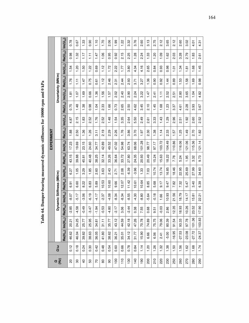
164
Ta
ble
64
. D
am
per
-bea
rin
g m
easu
red
dy
na
mic
sti
ffn
esse
s fo
r 1
000
0 r
pm
an
d 0
kP
a
EX
PE
RIM
EN
T
Un
cert
ain
ty (
MN
/m)
Im(U
yy)
0.7
8
0.6
7
1.3
3
0.9
0
1.1
0
1.7
0
2.0
6
1.9
9
1.2
2
3.3
2
3.7
6
2.6
0
3.1
3
2.7
5
2.1
2
3.6
5
2.1
2
2.6
0
3.0
2
4.0
1
4.3
1
Re(U
yy)
0.9
8
1.3
2
1.1
7
1.1
1
1.4
7
1.0
6
0.9
5
0.9
2
2.1
5
2.2
5
1.2
8
2.2
4
1.3
3
1.2
0
1.0
9
1.6
2
2.0
3
3.2
8
2.7
9
1.8
3
2.6
1
Im(U
yx)
1.5
4
1.2
0
1.5
0
1.2
2
0.6
9
1.1
2
1.7
2
2.2
2
1.7
7
3.8
0
4.3
4
4.1
6
2.6
5
0.8
4
0.9
3
0.9
8
1.0
1
1.3
4
1.8
1
1.6
8
1.4
5
Re(U
yx)
1.7
6
1.1
1
1.4
7
0.7
5
0.6
1
1.1
2
2.4
6
2.3
1
2.4
4
2.9
3
3.7
1
3.2
7
1.3
6
0.9
0
0.9
2
1.4
4
0.8
9
1.5
3
1.5
8
1.6
9
0.9
8
Im(U
xy)
1.8
1
1.0
7
1.6
9
0.6
6
1.3
6
1.5
6
1.5
7
2.0
2
2.4
0
2.9
0
2.2
4
3.2
2
1.4
7
2.4
1
1.1
1
2.5
2
2.5
1
2.8
0
3.6
5
1.0
4
4.8
2
Re(U
xy)
0.7
5
1.4
8
1.3
8
0.9
8
1.0
4
2.3
3
1.6
6
0.7
3
2.6
5
2.5
0
4.6
2
3.4
5
2.1
0
1.4
5
1.6
8
1.2
3
3.3
7
4.6
1
2.2
8
3.9
3
3.6
7
Im(U
xx)
4.8
7
2.1
5
1.8
3
2.5
2
1.7
6
2.5
2
1.4
8
1.5
4
3.3
5
2.6
4
5.5
0
2.4
9
2.6
1
3.3
3
1.4
3
1.2
9
2.9
6
2.5
1
1.9
2
2.6
0
2.5
2
Re(U
xx)
1.8
8
2.5
0
1.3
6
1.2
6
3.1
1
2.1
9
2.2
9
2.2
6
1.7
6
3.8
6
3.7
0
1.9
7
2.3
0
1.3
8
1.1
4
2.3
3
1.5
7
1.2
5
1.4
9
2.7
0
1.8
2
Dyn
am
ic S
tiff
ness (
MN
/m)
Im(H
yy)
17.2
3
19.6
9
23.1
5
24.6
0
34.7
7
42.8
9
49.5
2
47.0
2
54.9
8
63.7
4
68.0
6
101.2
8
98.7
7
97.1
7
103.7
2
104.4
9
110.8
6
116.0
6
121.0
6
115.3
6
121.1
4
Re(H
yy)
43.1
5
39.8
8
45.8
1
40.4
8
38.2
5
32.1
4
33.2
6
36.6
4
33.7
2
27.8
0
24.3
5
20.9
3
20.4
9
15.2
4
15.6
3
18.2
2
7.7
8
5.2
4
1.9
5
3.3
2
9.7
3
Im(H
yx)
6.2
7
1.0
5
3.2
9
1.8
5
2.6
0
3.6
3
2.4
3
2.7
1
2.0
8
-6.3
9
-3.9
6
1.3
3
7.0
3
10.7
4
13.7
4
16.8
5
18.4
6
22.9
5
25.6
9
27.9
9
34.6
0
Re(H
yx)
6.9
1
6.6
0
8.2
2
6.8
3
5.8
9
10.5
3
10.6
0
9.6
6
12.0
7
11.4
2
10.6
1
10.6
4
8.8
5
5.6
8
9.1
7
9.4
7
7.8
2
7.3
2
5.4
7
3.4
0
6.3
9
Im(H
xy)
-8.0
7
-5.1
7
-3.0
6
-6.1
9
-4.1
7
-2.3
7
-4.0
8
-8.3
4
-8.3
4
-8.5
5
-4.3
0
-8.8
0
-5.6
4
-0.1
8
1.6
6
10.9
3
21.5
6
18.7
9
14.1
7
15.8
1
22.2
1
Re(H
xy)
-2.8
5
-4.5
8
-0.4
9
-3.4
7
-1.9
4
-0.5
3
-4.8
0
-2.1
7
3.0
6
-2.4
4
0.3
8
7.5
5
0.6
8
9.5
1
-0.0
3
2.8
6
12.3
5
18.9
3
10.2
6
23.5
2
17.9
0
Im(H
xx)
20.2
1
24.2
5
25.7
7
25.9
5
34.8
1
31.1
1
35.7
7
43.1
2
44.5
9
42.1
8
47.2
6
70.7
8
74.8
9
75.7
5
79.0
6
80.3
9
91.5
4
93.3
3
97.7
8
101.3
6
103.8
3
Re(H
xx)
46.6
2
46.0
4
39.8
2
38.6
3
36.0
5
41.8
0
38.6
2
36.2
1
35.0
1
34.1
2
31.7
7
15.9
0
6.6
6
6.0
6
2.4
1
-5.0
0
-16.9
5
-27.5
3
-23.0
8
-27.7
2
-24.3
7
Ω/ω
0.1
2
0.1
8
0.2
4
0.3
0
0.4
2
0.4
8
0.5
4
0.6
0
0.6
6
0.7
8
0.8
4
1.1
4
1.2
0
1.2
6
1.3
2
1.3
8
1.5
0
1.5
6
1.6
2
1.6
8
1.7
4
Ω
(Hz)
20
30
40
50
70
80
90
100
110
130
140
190
200
210
220
230
250
260
270
280
290
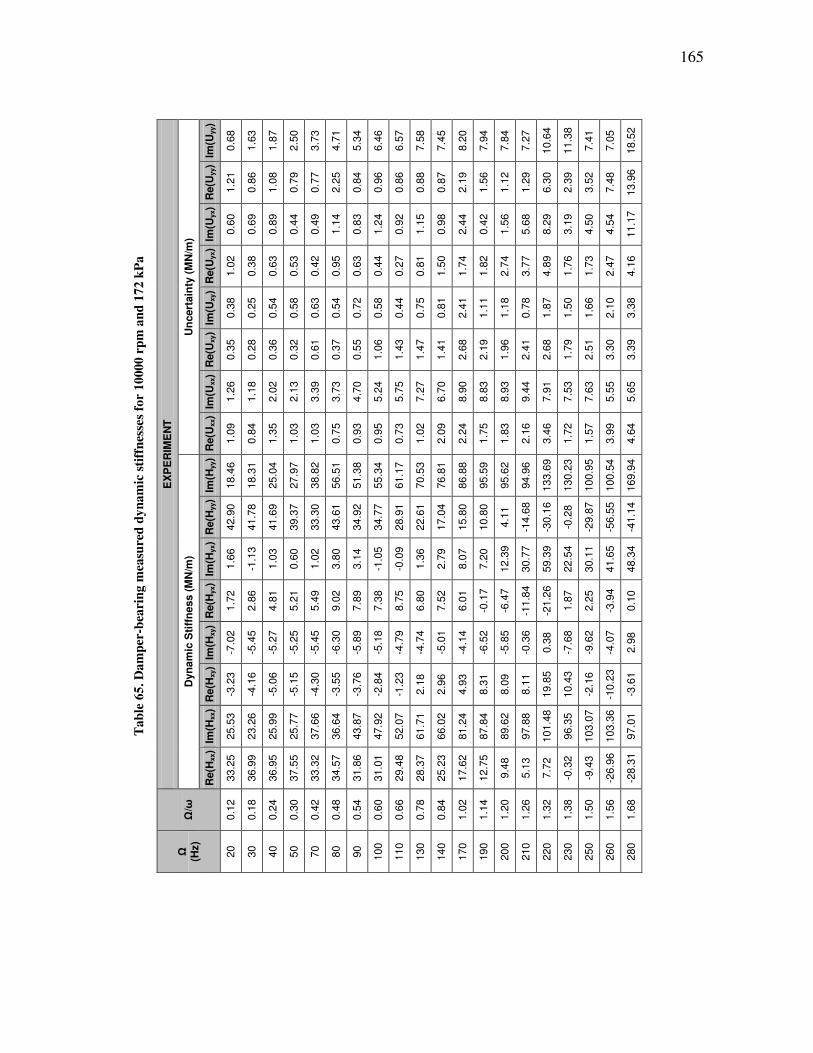
165
Ta
ble
65
. D
am
per
-bea
rin
g m
easu
red
dy
na
mic
sti
ffn
esse
s fo
r 1
000
0 r
pm
an
d 1
72 k
Pa
EX
PE
RIM
EN
T
Un
cert
ain
ty (
MN
/m)
Im(U
yy)
0.6
8
1.6
3
1.8
7
2.5
0
3.7
3
4.7
1
5.3
4
6.4
6
6.5
7
7.5
8
7.4
5
8.2
0
7.9
4
7.8
4
7.2
7
10.6
4
11.3
8
7.4
1
7.0
5
18.5
2
Re(U
yy)
1.2
1
0.8
6
1.0
8
0.7
9
0.7
7
2.2
5
0.8
4
0.9
6
0.8
6
0.8
8
0.8
7
2.1
9
1.5
6
1.1
2
1.2
9
6.3
0
2.3
9
3.5
2
7.4
8
13.9
6
Im(U
yx)
0.6
0
0.6
9
0.8
9
0.4
4
0.4
9
1.1
4
0.8
3
1.2
4
0.9
2
1.1
5
0.9
8
2.4
4
0.4
2
1.5
6
5.6
8
8.2
9
3.1
9
4.5
0
4.5
4
11.1
7
Re(U
yx)
1.0
2
0.3
8
0.6
3
0.5
3
0.4
2
0.9
5
0.6
3
0.4
4
0.2
7
0.8
1
1.5
0
1.7
4
1.8
2
2.7
4
3.7
7
4.8
9
1.7
6
1.7
3
2.4
7
4.1
6
Im(U
xy)
0.3
8
0.2
5
0.5
4
0.5
8
0.6
3
0.5
4
0.7
2
0.5
8
0.4
4
0.7
5
0.8
1
2.4
1
1.1
1
1.1
8
0.7
8
1.8
7
1.5
0
1.6
6
2.1
0
3.3
8
Re(U
xy)
0.3
5
0.2
8
0.3
6
0.3
2
0.6
1
0.3
7
0.5
5
1.0
6
1.4
3
1.4
7
1.4
1
2.6
8
2.1
9
1.9
6
2.4
1
2.6
8
1.7
9
2.5
1
3.3
0
3.3
9
Im(U
xx)
1.2
6
1.1
8
2.0
2
2.1
3
3.3
9
3.7
3
4.7
0
5.2
4
5.7
5
7.2
7
6.7
0
8.9
0
8.8
3
8.9
3
9.4
4
7.9
1
7.5
3
7.6
3
5.5
5
5.6
5
Re(U
xx)
1.0
9
0.8
4
1.3
5
1.0
3
1.0
3
0.7
5
0.9
3
0.9
5
0.7
3
1.0
2
2.0
9
2.2
4
1.7
5
1.8
3
2.1
6
3.4
6
1.7
2
1.5
7
3.9
9
4.6
4
Dyn
am
ic S
tiff
ness (
MN
/m)
Im(H
yy)
18.4
6
18.3
1
25.0
4
27.9
7
38.8
2
56.5
1
51.3
8
55.3
4
61.1
7
70.5
3
76.8
1
86.8
8
95.5
9
95.6
2
94.9
6
133.6
9
130.2
3
100.9
5
100.5
4
169.9
4
Re(H
yy)
42.9
0
41.7
8
41.6
9
39.3
7
33.3
0
43.6
1
34.9
2
34.7
7
28.9
1
22.6
1
17.0
4
15.8
0
10.8
0
4.1
1
-14.6
8
-30.1
6
-0.2
8
-29.8
7
-56.5
5
-41.1
4
Im(H
yx)
1.6
6
-1.1
3
1.0
3
0.6
0
1.0
2
3.8
0
3.1
4
-1.0
5
-0.0
9
1.3
6
2.7
9
8.0
7
7.2
0
12.3
9
30.7
7
59.3
9
22.5
4
30.1
1
41.6
5
48.3
4
Re(H
yx)
1.7
2
2.8
6
4.8
1
5.2
1
5.4
9
9.0
2
7.8
9
7.3
8
8.7
5
6.8
0
7.5
2
6.0
1
-0.1
7
-6.4
7
-11.8
4
-21.2
6
1.8
7
2.2
5
-3.9
4
0.1
0
Im(H
xy)
-7.0
2
-5.4
5
-5.2
7
-5.2
5
-5.4
5
-6.3
0
-5.8
9
-5.1
8
-4.7
9
-4.7
4
-5.0
1
-4.1
4
-6.5
2
-5.8
5
-0.3
6
0.3
8
-7.6
8
-9.6
2
-4.0
7
2.9
8
Re(H
xy)
-3.2
3
-4.1
6
-5.0
6
-5.1
5
-4.3
0
-3.5
5
-3.7
6
-2.8
4
-1.2
3
2.1
8
2.9
6
4.9
3
8.3
1
8.0
9
8.1
1
19.8
5
10.4
3
-2.1
6
-10.2
3
-3.6
1
Im(H
xx)
25.5
3
23.2
6
25.9
9
25.7
7
37.6
6
36.6
4
43.8
7
47.9
2
52.0
7
61.7
1
66.0
2
81.2
4
87.8
4
89.6
2
97.8
8
101.4
8
96.3
5
103.0
7
103.3
6
97.0
1
Re(H
xx)
33.2
5
36.9
9
36.9
5
37.5
5
33.3
2
34.5
7
31.8
6
31.0
1
29.4
8
28.3
7
25.2
3
17.6
2
12.7
5
9.4
8
5.1
3
7.7
2
-0.3
2
-9.4
3
-26.9
6
-28.3
1
Ω/ω
0.1
2
0.1
8
0.2
4
0.3
0
0.4
2
0.4
8
0.5
4
0.6
0
0.6
6
0.7
8
0.8
4
1.0
2
1.1
4
1.2
0
1.2
6
1.3
2
1.3
8
1.5
0
1.5
6
1.6
8
Ω
(Hz)
20
30
40
50
70
80
90
100
110
130
140
170
190
200
210
220
230
250
260
280
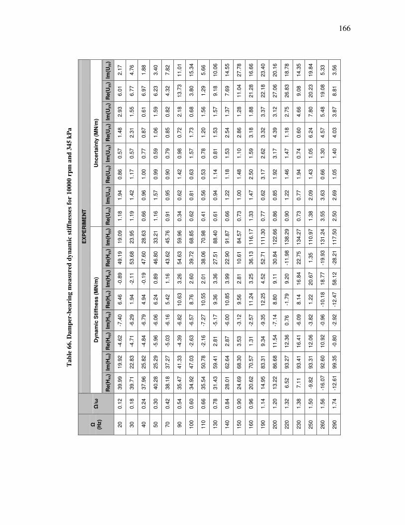
166
Ta
ble
66
. D
am
per
-bea
rin
g m
easu
red
dy
na
mic
sti
ffn
esse
s fo
r 1
000
0 r
pm
an
d 3
45 k
Pa
EX
PE
RIM
EN
T
Un
cert
ain
ty (
MN
/m)
Im(U
yy)
2.1
7
4.7
6
1.8
8
3.4
0
7.8
2
11.0
1
15.3
4
5.6
6
10.0
6
14.5
5
27.7
8
16.6
6
23.4
0
20.1
6
18.7
8
14.3
5
19.8
4
5.3
3
3.5
6
Re(U
yy)
6.0
1
6.7
7
6.9
7
6.2
3
4.3
2
13.7
3
3.8
0
1.2
9
9.1
8
7.6
9
11.0
4
21.2
8
22.1
8
27.0
6
26.8
3
9.0
8
20.2
3
19.0
8
8.8
1
Im(U
yx)
2.9
3
1.5
5
0.6
1
1.5
9
0.8
2
2.1
8
0.6
8
1.5
6
1.5
7
1.3
7
1.2
8
1.8
8
3.3
7
3.1
2
2.7
5
4.6
6
7.8
0
5.4
8
3.8
7
Re(U
yx)
1.4
8
2.3
1
0.8
7
1.0
6
0.8
5
0.7
2
1.7
3
1.2
0
1.5
3
2.5
4
2.8
6
3.1
8
3.3
2
4.3
9
1.1
8
0.6
0
6.2
4
4.5
7
4.0
3
Im(U
xy)
0.5
7
0.5
7
0.7
7
0.5
9
0.7
9
0.9
8
1.5
7
0.7
8
0.8
1
1.5
3
1.1
0
1.5
9
2.6
2
3.1
7
1.4
7
0.7
4
1.0
5
1.3
0
1.4
0
Re(U
xy)
0.8
6
1.1
7
1.0
0
0.9
9
0.9
0
1.4
2
0.6
3
0.5
3
1.1
4
1.1
8
1.4
8
2.5
0
3.1
7
1.9
2
1.4
6
1.9
4
1.4
3
0.6
6
1.0
5
Im(U
xx)
1.9
4
1.4
2
0.9
6
1.5
7
0.9
5
0.6
2
0.8
1
0.5
6
0.9
4
1.2
2
1.0
0
1.4
7
0.6
2
0.8
5
1.2
2
0.7
7
2.0
9
3.6
3
2.6
9
Re(U
xx)
1.1
8
1.1
9
0.6
6
1.1
6
0.9
1
0.3
4
0.6
2
0.4
1
0.6
1
0.6
6
0.7
3
1.3
3
0.7
7
0.8
6
0.9
0
0.7
3
1.3
8
3.5
5
2.5
0
Dyn
am
ic S
tiff
ness (
MN
/m)
Im(H
yy)
19.0
9
23.9
5
28.6
3
33.2
1
45.7
6
59.9
6
68.8
5
70.9
8
88.4
0
91.8
7
84.5
7
116.1
7
111.3
0
122.6
6
138.2
9
134.2
7
110.9
7
131.2
4
117.5
0
Re(H
yy)
49.1
9
53.6
8
47.6
0
46.8
0
43.6
2
54.6
3
39.7
2
38.0
6
27.5
1
22.9
0
10.6
1
36.1
3
52.7
1
30.8
4
-11.9
8
22.7
5
1.3
5
-19.9
3
-28.2
1
Im(H
yx)
-0.8
9
-2.1
1
-0.1
9
0.8
9
1.1
6
3.2
6
2.6
0
2.0
1
3.3
6
3.9
9
2.8
1
3.2
5
4.5
2
9.1
1
9.2
0
16.8
4
20.6
7
18.7
7
58.1
2
Re(H
yx)
6.4
6
1.9
4
4.9
4
6.2
4
5.4
2
10.6
3
8.7
6
10.5
5
9.3
6
10.8
5
9.5
6
11.2
4
12.2
5
8.8
0
-1.7
9
8.1
4
1.2
2
-10.1
8
-12.4
7
Im(H
xy)
-7.4
0
-6.2
9
-6.7
9
-6.0
6
-6.1
6
-6.8
2
-6.5
7
-7.2
7
-5.1
7
-6.0
0
-3.1
2
-2.5
7
-9.3
5
-7.1
4
0.7
6
-6.0
9
-3.8
2
-0.9
6
-2.9
2
Re(H
xy)
-4.6
2
-4.7
1
-4.8
4
-5.9
6
-5.0
3
-4.3
9
-2.6
3
-2.1
6
2.8
1
2.8
7
3.5
3
1.3
1
9.3
4
11.5
4
12.3
6
16.4
1
12.0
6
10.9
2
-0.8
0
Im(H
xx)
19.9
2
22.8
3
25.8
2
25.2
9
37.2
7
41.3
3
47.0
3
50.7
8
59.4
1
62.6
4
68.3
0
70.5
7
83.3
1
86.6
8
93.2
7
93.4
1
93.3
1
92.6
0
99.3
5
Re(H
xx)
39.9
9
39.7
1
37.9
6
40.2
8
38.1
8
35.4
7
34.9
2
35.5
4
31.4
3
28.0
1
24.6
9
20.6
2
14.9
5
13.2
2
6.5
2
7.1
1
-9.8
2
-16.0
7
-12.6
1
Ω/ω
0.1
2
0.1
8
0.2
4
0.3
0
0.4
2
0.5
4
0.6
0
0.6
6
0.7
8
0.8
4
0.9
0
0.9
6
1.1
4
1.2
0
1.3
2
1.3
8
1.5
0
1.5
6
1.7
4
Ω
(Hz)
20
30
40
50
70
90
100
110
130
140
150
160
190
200
220
230
250
260
290

167
Ta
ble
67
. D
am
per
-bea
rin
g m
easu
red
dy
na
mic
sti
ffn
esse
s fo
r 1
000
0 r
pm
an
d 5
17 k
Pa
EX
PE
RIM
EN
T
Un
cert
ain
ty (
MN
/m)
Im(U
yy)
0.9
0
0.5
6
0.3
7
0.4
2
0.6
3
0.8
0
0.9
1
1.1
8
1.0
7
1.6
9
1.9
2
2.6
7
2.3
2
1.6
3
2.7
7
Re(U
yy)
0.6
9
0.4
7
0.5
3
0.6
2
0.4
1
0.4
6
0.4
4
0.7
5
0.7
4
0.9
7
0.8
2
0.7
7
0.8
2
0.7
2
0.6
9
Im(U
yx)
2.2
4
0.9
9
0.9
1
0.6
5
0.4
9
0.4
8
0.3
8
0.6
1
0.3
1
0.7
0
0.6
0
0.4
9
0.5
2
0.7
2
0.5
9
Re(U
yx)
1.1
8
0.9
9
0.7
4
0.7
4
0.9
9
0.4
4
0.5
7
0.5
4
0.5
2
0.3
5
0.6
0
0.8
3
0.4
1
0.4
9
0.5
2
Im(U
xy)
0.3
2
0.4
0
0.4
2
0.4
7
0.4
1
0.2
6
0.5
4
0.3
4
0.5
8
0.5
7
0.6
2
0.5
7
0.5
4
0.6
0
0.8
7
Re(U
xy)
0.7
3
0.3
6
0.5
0
0.5
5
0.5
7
0.6
3
0.6
7
0.4
1
0.8
6
1.2
7
1.6
5
2.0
5
0.8
7
0.8
3
1.1
4
Im(U
xx)
1.7
3
1.3
7
0.7
7
1.2
1
0.8
1
1.0
2
1.0
2
0.9
7
1.4
2
1.4
0
1.4
6
1.7
5
1.4
5
1.3
6
1.2
2
Re(U
xx)
1.3
5
1.0
8
1.0
4
1.0
6
0.7
9
0.7
5
0.4
8
0.4
7
0.6
8
0.7
1
0.5
9
1.1
9
0.7
4
0.6
3
0.5
8
Dyn
am
ic S
tiff
ness (
MN
/m)
Im(H
yy)
19.9
2
19.9
1
26.5
1
29.1
8
38.2
3
49.4
9
52.8
7
58.6
0
68.4
2
75.7
0
73.9
9
94.9
7
96.5
6
99.5
8
116.1
9
Re(H
yy)
46.1
0
46.2
1
45.6
4
45.0
4
40.8
8
43.8
3
41.6
3
37.5
5
30.5
4
25.5
0
16.8
8
17.6
1
6.8
4
-12.4
3
17.5
1
Im(H
yx)
-2.1
8
-1.8
3
-0.9
9
2.0
4
1.5
4
3.1
0
2.7
2
2.6
7
3.2
6
4.1
7
3.8
3
7.6
3
10.0
8
9.4
7
12.8
0
Re(H
yx)
5.5
2
2.7
3
5.0
9
6.0
7
5.9
2
7.5
5
7.1
2
8.8
9
8.1
9
10.1
7
9.6
3
8.4
3
6.7
7
5.5
2
7.0
8
Im(H
xy)
-6.7
4
-4.6
9
-5.4
9
-5.2
3
-4.9
5
-4.5
5
-4.2
3
-5.4
2
-3.0
6
-3.5
2
-1.8
3
-3.2
3
-0.4
3
2.4
3
-3.3
2
Re(H
xy)
-4.7
8
-4.5
1
-4.2
8
-5.3
1
-4.5
9
-3.3
8
-3.0
6
-2.1
2
2.2
2
2.6
8
3.3
6
9.2
6
9.0
5
10.4
5
14.1
6
Im(H
xx)
19.9
7
21.8
9
26.5
3
26.3
6
38.2
2
40.1
4
47.1
5
51.1
2
58.6
8
60.6
0
65.3
9
84.6
3
89.0
6
92.5
0
94.5
0
Re(H
xx)
43.6
1
42.4
6
38.7
0
41.6
9
41.8
5
37.9
9
38.1
0
39.4
3
32.9
5
29.7
9
26.6
1
14.4
5
10.6
5
10.0
0
9.1
6
Ω/ω
0.1
2
0.1
8
0.2
4
0.3
0
0.4
2
0.5
4
0.6
0
0.6
6
0.7
8
0.8
4
0.9
0
1.2
0
1.2
6
1.3
2
1.3
8
Ω
(Hz)
20
30
40
50
70
90
100
110
130
140
150
200
210
220
230
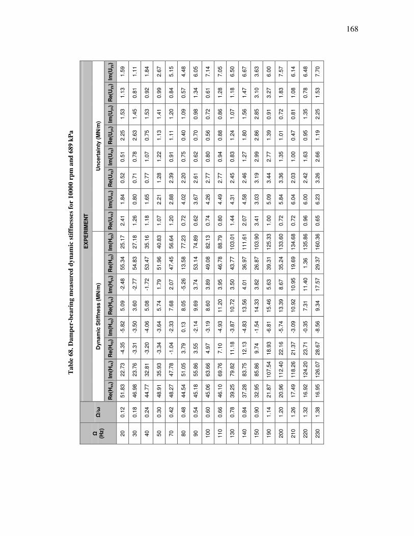
168
Ta
ble
68
. D
am
per
-bea
rin
g m
easu
red
dy
na
mic
sti
ffn
esse
s fo
r 1
000
0 r
pm
an
d 6
89 k
Pa
EX
PE
RIM
EN
T
Un
cert
ain
ty (
MN
/m)
Im(U
yy)
1.5
9
1.1
1
1.8
4
2.6
7
5.1
5
4.4
8
6.0
5
7.1
4
7.0
5
6.5
0
6.6
7
3.6
3
6.0
0
7.5
7
6.1
4
6.4
8
7.7
0
Re(U
yy)
1.1
3
0.8
1
0.9
2
0.9
9
0.8
4
0.5
7
1.3
4
0.6
1
1.2
8
1.1
8
1.4
7
3.1
0
3.2
7
1.8
3
1.0
8
0.7
8
1.5
3
Im(U
yx)
1.5
3
1.4
5
1.5
3
1.4
1
1.2
0
1.0
9
0.9
8
0.7
2
0.8
6
1.0
7
1.5
6
2.8
5
0.9
1
0.7
2
0.8
1
1.3
5
2.2
5
Re(U
yx)
2.2
5
2.6
3
0.7
5
1.1
3
1.1
1
0.4
0
0.7
0
0.5
6
0.8
8
1.2
4
1.8
0
2.8
6
1.3
9
1.0
1
0.4
7
0.9
5
1.1
9
Im(U
xy)
0.5
1
0.7
8
1.0
7
1.2
2
0.9
1
0.7
5
0.6
2
0.8
0
0.9
4
0.8
3
1.2
7
2.9
9
2.7
7
1.3
5
1.0
0
1.6
3
2.6
6
Re(U
xy)
0.5
2
0.7
1
0.7
7
1.2
8
2.3
9
2.2
0
2.6
1
2.7
7
2.7
7
2.4
5
2.4
6
3.1
9
3.4
4
3.3
6
2.0
3
2.4
2
3.2
6
Im(U
xx)
1.8
4
0.8
0
1.6
5
2.2
1
2.8
8
4.0
2
3.6
7
4.2
6
4.4
9
4.3
1
4.5
8
3.0
3
5.0
9
5.8
4
6.0
4
6.0
0
6.2
3
Re(U
xx)
2.4
1
1.2
6
1.1
8
1.0
7
1.2
0
0.7
2
0.6
2
0.7
4
0.8
0
1.4
4
2.0
7
3.4
1
1.0
0
0.7
2
0.7
2
0.9
6
0.6
5
Dyn
am
ic S
tiff
ness (
MN
/m)
Im(H
yy)
25.1
7
27.1
8
35.1
6
40.8
3
56.6
4
77.2
3
74.8
9
82.1
3
88.7
9
103.0
1
111.6
1
103.9
0
125.3
3
133.6
0
134.6
8
135.8
6
160.3
6
Re(H
yy)
55.3
4
54.8
3
53.4
7
51.9
6
47.4
5
13.5
8
53.1
4
49.0
8
46.7
8
43.7
7
36.9
7
26.8
7
39.3
1
35.2
4
19.6
9
1.3
6
29.3
7
Im(H
yx)
-2.4
8
-2.7
7
-1.7
2
1.7
9
2.0
7
-5.2
6
3.7
4
3.8
9
3.9
5
3.5
0
4.0
1
3.8
2
5.6
3
8.6
7
10.9
5
11.4
0
17.5
7
Re(H
yx)
5.0
9
3.6
0
5.0
8
5.7
4
7.6
8
8.0
5
9.6
9
8.6
0
11.2
0
10.7
2
13.5
6
14.3
3
15.4
6
13.3
9
10.9
2
7.3
1
9.3
4
Im(H
xy)
-5.8
2
-3.5
0
-4.0
6
-3.6
4
-2.3
3
0.1
3
-2.1
4
-3.1
9
-4.9
3
-3.8
7
-4.8
3
-1.5
4
-6.8
1
-5.7
4
-3.0
9
-0.3
5
-8.5
6
Re(H
xy)
-4.3
5
-3.3
1
-3.2
0
-3.3
4
-1.0
4
3.7
9
3.5
5
4.9
7
7.1
0
11.1
8
12.1
3
9.7
4
18.9
3
22.1
6
21.3
7
23.7
1
28.6
7
Im(H
xx)
22.7
3
23.7
6
32.8
1
35.9
3
47.7
8
51.0
5
55.8
6
63.6
6
69.7
6
79.8
2
83.7
5
85.8
6
107.5
4
112.4
0
118.2
6
124.2
0
126.0
7
Re(H
xx)
51.8
3
46.9
8
44.7
7
48.9
1
48.2
7
44.5
4
45.1
8
45.0
6
46.1
0
39.2
5
37.2
8
32.9
5
21.8
7
20.9
6
17.4
9
16.9
2
16.9
5
Ω/ω
0.1
2
0.1
8
0.2
4
0.3
0
0.4
2
0.4
8
0.5
4
0.6
0
0.6
6
0.7
8
0.8
4
0.9
0
1.1
4
1.2
0
1.2
6
1.3
2
1.3
8
Ω
(Hz)
20
30
40
50
70
80
90
100
110
130
140
150
190
200
210
220
230
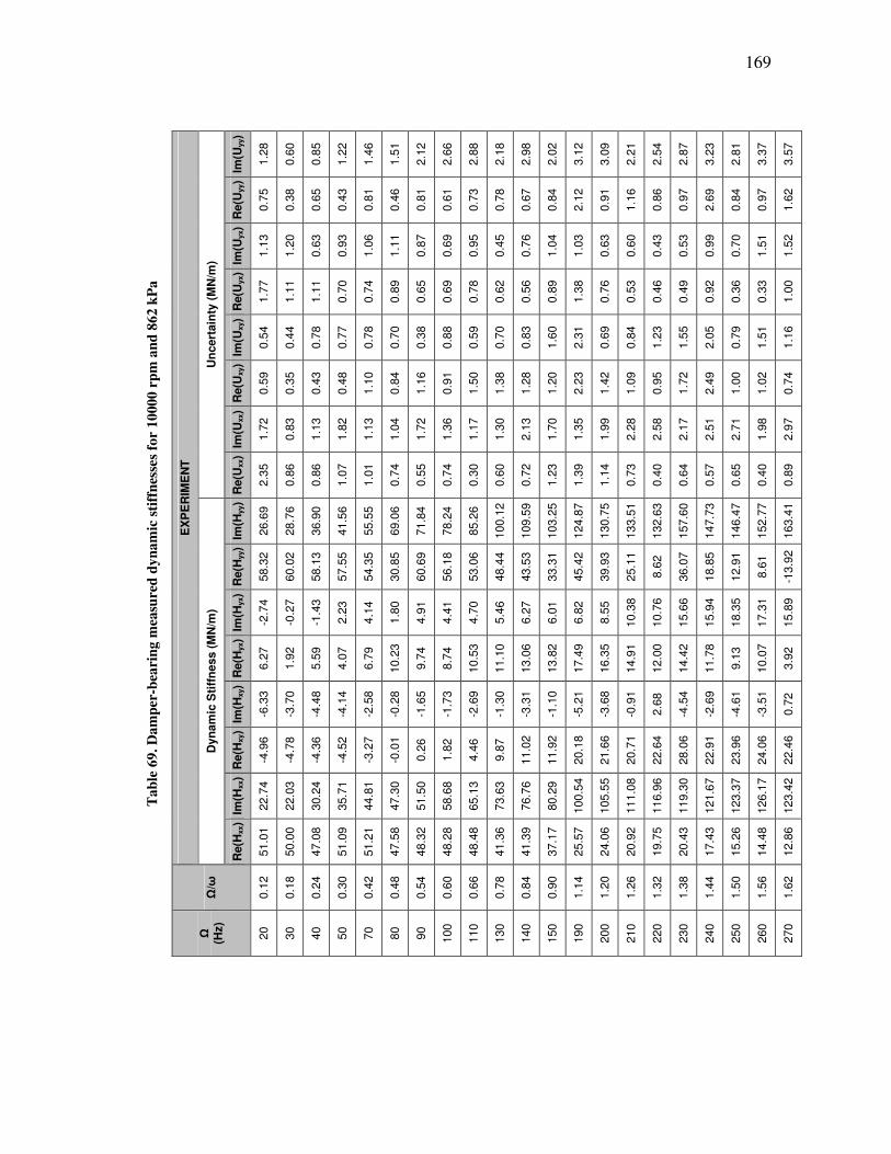
169
Ta
ble
69
. D
am
per
-bea
rin
g m
easu
red
dy
na
mic
sti
ffn
esse
s fo
r 1
000
0 r
pm
an
d 8
62 k
Pa
EX
PE
RIM
EN
T
Un
cert
ain
ty (
MN
/m)
Im(U
yy)
1.2
8
0.6
0
0.8
5
1.2
2
1.4
6
1.5
1
2.1
2
2.6
6
2.8
8
2.1
8
2.9
8
2.0
2
3.1
2
3.0
9
2.2
1
2.5
4
2.8
7
3.2
3
2.8
1
3.3
7
3.5
7
Re(U
yy)
0.7
5
0.3
8
0.6
5
0.4
3
0.8
1
0.4
6
0.8
1
0.6
1
0.7
3
0.7
8
0.6
7
0.8
4
2.1
2
0.9
1
1.1
6
0.8
6
0.9
7
2.6
9
0.8
4
0.9
7
1.6
2
Im(U
yx)
1.1
3
1.2
0
0.6
3
0.9
3
1.0
6
1.1
1
0.8
7
0.6
9
0.9
5
0.4
5
0.7
6
1.0
4
1.0
3
0.6
3
0.6
0
0.4
3
0.5
3
0.9
9
0.7
0
1.5
1
1.5
2
Re(U
yx)
1.7
7
1.1
1
1.1
1
0.7
0
0.7
4
0.8
9
0.6
5
0.6
9
0.7
8
0.6
2
0.5
6
0.8
9
1.3
8
0.7
6
0.5
3
0.4
6
0.4
9
0.9
2
0.3
6
0.3
3
1.0
0
Im(U
xy)
0.5
4
0.4
4
0.7
8
0.7
7
0.7
8
0.7
0
0.3
8
0.8
8
0.5
9
0.7
0
0.8
3
1.6
0
2.3
1
0.6
9
0.8
4
1.2
3
1.5
5
2.0
5
0.7
9
1.5
1
1.1
6
Re(U
xy)
0.5
9
0.3
5
0.4
3
0.4
8
1.1
0
0.8
4
1.1
6
0.9
1
1.5
0
1.3
8
1.2
8
1.2
0
2.2
3
1.4
2
1.0
9
0.9
5
1.7
2
2.4
9
1.0
0
1.0
2
0.7
4
Im(U
xx)
1.7
2
0.8
3
1.1
3
1.8
2
1.1
3
1.0
4
1.7
2
1.3
6
1.1
7
1.3
0
2.1
3
1.7
0
1.3
5
1.9
9
2.2
8
2.5
8
2.1
7
2.5
1
2.7
1
1.9
8
2.9
7
Re(U
xx)
2.3
5
0.8
6
0.8
6
1.0
7
1.0
1
0.7
4
0.5
5
0.7
4
0.3
0
0.6
0
0.7
2
1.2
3
1.3
9
1.1
4
0.7
3
0.4
0
0.6
4
0.5
7
0.6
5
0.4
0
0.8
9
Dyn
am
ic S
tiff
ness (
MN
/m)
Im(H
yy)
26.6
9
28.7
6
36.9
0
41.5
6
55.5
5
69.0
6
71.8
4
78.2
4
85.2
6
100.1
2
109.5
9
103.2
5
124.8
7
130.7
5
133.5
1
132.6
3
157.6
0
147.7
3
146.4
7
152.7
7
163.4
1
Re(H
yy)
58.3
2
60.0
2
58.1
3
57.5
5
54.3
5
30.8
5
60.6
9
56.1
8
53.0
6
48.4
4
43.5
3
33.3
1
45.4
2
39.9
3
25.1
1
8.6
2
36.0
7
18.8
5
12.9
1
8.6
1
-13.9
2
Im(H
yx)
-2.7
4
-0.2
7
-1.4
3
2.2
3
4.1
4
1.8
0
4.9
1
4.4
1
4.7
0
5.4
6
6.2
7
6.0
1
6.8
2
8.5
5
10.3
8
10.7
6
15.6
6
15.9
4
18.3
5
17.3
1
15.8
9
Re(H
yx)
6.2
7
1.9
2
5.5
9
4.0
7
6.7
9
10.2
3
9.7
4
8.7
4
10.5
3
11.1
0
13.0
6
13.8
2
17.4
9
16.3
5
14.9
1
12.0
0
14.4
2
11.7
8
9.1
3
10.0
7
3.9
2
Im(H
xy)
-6.3
3
-3.7
0
-4.4
8
-4.1
4
-2.5
8
-0.2
8
-1.6
5
-1.7
3
-2.6
9
-1.3
0
-3.3
1
-1.1
0
-5.2
1
-3.6
8
-0.9
1
2.6
8
-4.5
4
-2.6
9
-4.6
1
-3.5
1
0.7
2
Re(H
xy)
-4.9
6
-4.7
8
-4.3
6
-4.5
2
-3.2
7
-0.0
1
0.2
6
1.8
2
4.4
6
9.8
7
11.0
2
11.9
2
20.1
8
21.6
6
20.7
1
22.6
4
28.0
6
22.9
1
23.9
6
24.0
6
22.4
6
Im(H
xx)
22.7
4
22.0
3
30.2
4
35.7
1
44.8
1
47.3
0
51.5
0
58.6
8
65.1
3
73.6
3
76.7
6
80.2
9
100.5
4
105.5
5
111.0
8
116.9
6
119.3
0
121.6
7
123.3
7
126.1
7
123.4
2
Re(H
xx)
51.0
1
50.0
0
47.0
8
51.0
9
51.2
1
47.5
8
48.3
2
48.2
8
48.4
8
41.3
6
41.3
9
37.1
7
25.5
7
24.0
6
20.9
2
19.7
5
20.4
3
17.4
3
15.2
6
14.4
8
12.8
6
Ω/ω
0.1
2
0.1
8
0.2
4
0.3
0
0.4
2
0.4
8
0.5
4
0.6
0
0.6
6
0.7
8
0.8
4
0.9
0
1.1
4
1.2
0
1.2
6
1.3
2
1.3
8
1.4
4
1.5
0
1.5
6
1.6
2
Ω
(Hz)
20
30
40
50
70
80
90
100
110
130
140
150
190
200
210
220
230
240
250
260
270

170
Ta
ble
70
. D
am
per
-bea
rin
g m
easu
red
dy
na
mic
sti
ffn
esse
s fo
r 1
200
0 r
pm
an
d 0
kP
a
EX
PE
RIM
EN
T
Un
cert
ain
ty (
MN
/m)
Im(U
yy)
0.4
0
0.6
8
0.6
2
0.8
1
0.8
4
0.5
8
0.9
2
0.7
6
1.4
3
1.1
4
1.8
6
1.5
1
1.0
4
2.3
6
2.7
6
1.4
7
1.5
1
2.2
5
1.2
1
1.8
6
1.8
0
Re(U
yy)
1.2
2
1.2
3
0.5
7
0.6
3
1.0
1
0.6
5
0.4
7
0.7
3
0.9
4
1.7
3
0.7
9
1.3
1
2.2
4
3.0
4
2.6
1
1.7
3
1.1
0
1.5
9
1.7
2
1.6
9
1.1
2
Im(U
yx)
1.3
9
1.5
5
0.9
6
0.8
1
1.1
0
0.9
6
1.1
9
1.5
1
1.5
9
2.4
1
2.1
0
2.5
8
1.7
3
2.1
5
1.7
0
1.2
2
1.1
4
2.0
5
1.9
3
0.9
7
0.9
4
Re(U
yx)
1.5
9
1.4
5
1.0
2
0.9
1
0.8
3
0.9
4
0.9
2
1.0
2
1.3
1
1.4
4
4.3
0
2.8
0
1.2
5
1.3
2
1.8
4
1.3
9
2.7
4
1.4
6
1.4
7
0.9
6
1.6
9
Im(U
xy)
1.1
1
1.0
9
1.8
4
1.2
1
0.7
1
2.0
9
1.0
5
4.2
8
1.3
5
1.8
2
2.3
2
3.6
1
1.6
5
5.9
5
3.4
4
3.5
3
6.3
9
6.7
8
9.1
9
3.4
5
6.7
9
Re(U
xy)
1.1
0
0.8
1
3.3
2
0.9
9
1.2
4
1.2
3
1.6
6
1.1
7
2.7
1
2.1
3
2.4
6
4.2
2
2.3
1
6.2
9
4.0
6
3.8
8
3.7
7
2.3
6
3.5
5
3.6
1
2.5
0
Im(U
xx)
2.1
4
4.3
9
2.8
4
1.9
1
1.0
3
2.2
2
2.3
1
2.2
2
2.7
1
2.2
9
2.4
1
4.9
9
2.3
8
2.0
1
2.6
1
3.8
2
1.5
4
3.5
3
3.7
4
2.2
3
2.2
5
Re(U
xx)
2.2
9
4.5
8
2.9
1
1.4
8
1.2
5
1.7
5
1.5
9
1.7
1
2.2
9
3.1
1
4.6
0
3.9
5
1.8
3
3.7
4
2.3
8
2.5
8
2.2
7
2.3
3
1.8
5
1.6
9
1.1
1
Dyn
am
ic S
tiff
ness (
MN
/m)
Im(H
yy)
20.8
1
22.2
1
28.7
2
28.7
3
39.3
0
46.7
2
52.3
7
51.4
5
58.5
7
69.3
4
77.8
5
77.8
9
82.4
1
86.5
5
107.9
7
114.5
3
110.5
5
127.1
5
132.0
7
125.8
0
131.5
9
Re(H
yy)
47.3
2
44.9
6
51.1
9
46.3
0
44.6
3
39.1
9
41.2
2
44.9
1
39.1
9
32.4
4
32.7
7
30.9
5
31.9
9
29.9
4
28.7
6
25.5
2
28.9
7
12.4
4
13.1
5
19.3
9
21.9
2
Im(H
yx)
4.1
4
-0.1
6
2.3
2
2.1
4
1.5
9
3.7
4
3.7
6
1.0
5
1.8
9
-4.2
3
-12.3
9
-9.8
7
-0.1
0
1.1
6
11.1
2
13.1
6
14.1
0
18.4
8
22.8
3
24.7
8
33.7
4
Re(H
yx)
6.2
4
7.0
8
7.7
1
6.3
2
6.9
1
10.0
3
10.1
4
11.5
6
12.5
2
17.2
8
21.0
2
17.3
5
12.1
9
12.2
0
6.5
4
11.8
3
14.5
1
5.1
9
6.7
9
2.2
2
3.7
0
Im(H
xy)
-8.8
1
-9.0
4
-4.8
6
-7.3
5
-7.2
3
-3.2
0
-7.5
3
-12.0
6
-10.3
2
-10.4
6
-8.5
5
-10.1
5
-8.4
7
-11.6
6
-0.4
5
-1.8
5
8.5
2
12.6
5
7.0
0
19.3
1
19.7
0
Re(H
xy)
-2.6
2
-2.8
9
-1.1
3
-3.5
1
-4.4
0
-0.0
2
-6.9
1
-2.7
4
0.0
6
-0.7
3
4.7
8
8.1
3
6.4
1
6.0
7
17.1
3
7.0
6
8.9
2
17.7
1
11.8
7
25.2
2
23.5
1
Im(H
xx)
21.5
0
29.2
6
29.9
5
27.8
1
36.4
9
37.5
3
40.2
6
44.7
4
47.1
6
46.6
7
43.8
8
52.1
2
70.6
1
73.6
7
85.7
1
83.5
7
90.5
7
97.5
0
106.7
1
107.3
1
106.5
8
Re(H
xx)
47.9
5
47.9
7
45.2
1
43.4
0
40.6
3
47.3
4
43.8
0
41.1
0
38.9
9
40.2
7
31.7
8
29.0
8
30.5
0
24.8
4
11.0
3
8.0
0
1.1
4
-15.3
0
-16.2
1
-17.6
2
-17.9
7
Ω/ω
0.1
0
0.1
5
0.2
0
0.2
5
0.3
5
0.4
0
0.4
5
0.5
0
0.5
5
0.6
5
0.7
0
0.7
5
0.8
0
0.8
5
1.0
5
1.1
0
1.1
5
1.3
0
1.3
5
1.4
0
1.4
5
Ω
(Hz)
20
30
40
50
70
80
90
100
110
130
140
150
160
170
210
220
230
260
270
280
290
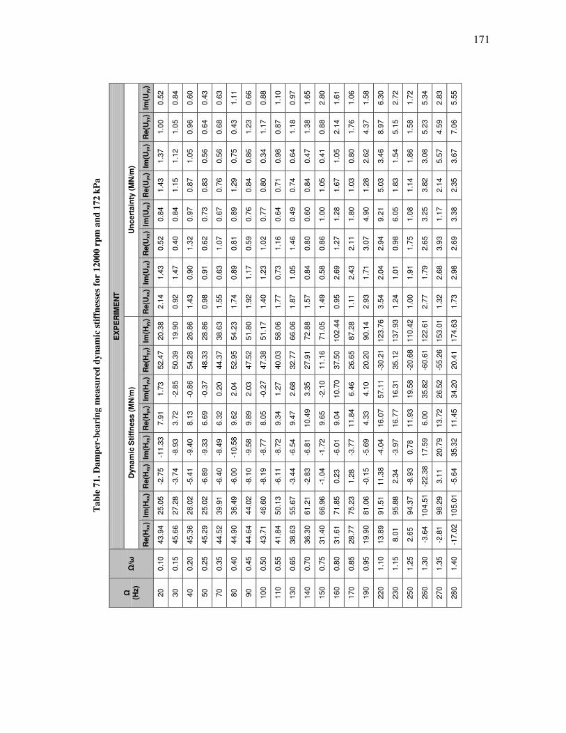
171
Ta
ble
71
. D
am
per
-bea
rin
g m
easu
red
dy
na
mic
sti
ffn
esse
s fo
r 1
200
0 r
pm
an
d 1
72 k
Pa
EX
PE
RIM
EN
T
Un
cert
ain
ty (
MN
/m)
Im(U
yy)
0.5
2
0.8
4
0.6
0
0.4
3
0.6
3
1.1
1
0.6
6
0.8
8
1.1
0
0.9
7
1.6
5
2.8
0
1.6
1
1.0
6
1.5
8
6.3
0
2.7
2
1.7
2
5.3
4
2.8
3
5.5
5
Re(U
yy)
1.0
0
1.0
5
0.9
6
0.6
4
0.6
8
0.4
3
1.2
3
1.1
7
0.8
7
1.1
8
1.3
8
0.8
8
2.1
4
1.7
6
4.3
7
8.9
7
5.1
5
1.5
8
5.2
3
4.5
9
7.0
6
Im(U
yx)
1.3
7
1.1
2
1.0
5
0.5
6
0.5
6
0.7
5
0.8
6
0.3
4
0.9
8
0.6
4
0.4
7
0.4
1
1.0
5
0.8
0
2.6
2
3.4
6
1.5
4
1.8
6
3.0
8
5.5
7
3.6
7
Re(U
yx)
1.4
3
1.1
5
0.8
7
0.8
3
0.7
6
1.2
9
0.8
4
0.8
0
0.7
1
0.7
4
0.8
4
1.0
5
1.6
7
1.0
3
1.2
8
5.0
3
1.8
3
1.1
4
3.8
2
2.1
4
2.3
5
Im(U
xy)
0.8
4
0.8
4
0.9
7
0.7
3
0.6
7
0.8
9
0.7
6
0.7
7
0.6
4
0.4
9
0.6
0
1.0
0
1.2
8
1.8
0
4.9
0
9.2
1
6.0
5
1.0
8
3.2
5
1.1
7
3.3
8
Re(U
xy)
0.5
2
0.4
0
1.3
2
0.6
2
1.0
7
0.8
1
0.5
9
1.0
2
1.1
6
1.4
6
0.8
0
0.8
6
1.2
7
2.1
1
3.0
7
2.9
4
0.9
8
1.7
5
2.6
5
3.9
3
2.6
9
Im(U
xx)
1.4
3
1.4
7
0.9
0
0.9
1
0.6
3
0.8
9
1.1
7
1.2
3
0.7
3
1.0
5
0.8
4
0.5
8
2.6
9
2.4
3
1.7
1
2.0
4
1.0
1
1.9
1
1.7
9
2.6
8
2.9
8
Re(U
xx)
2.1
4
0.9
2
1.4
3
0.9
8
1.5
5
1.7
4
1.9
2
1.4
0
1.7
7
1.8
7
1.5
7
1.4
9
0.9
5
1.1
1
2.9
3
3.5
4
1.2
4
1.0
0
2.7
7
1.3
2
1.7
3
Dyn
am
ic S
tiff
ness (
MN
/m)
Im(H
yy)
20.3
8
19.9
0
26.8
6
28.8
6
38.6
3
54.2
3
51.8
0
51.1
7
58.0
6
66.0
6
72.8
8
71.0
5
102.4
4
87.2
8
90.1
4
123.7
6
137.9
3
110.4
2
122.6
1
153.0
1
174.6
3
Re(H
yy)
52.4
7
50.3
9
54.2
8
48.3
3
44.3
7
52.9
5
47.5
2
47.3
8
40.0
3
32.7
7
27.9
1
11.1
6
37.5
0
26.6
5
20.2
0
-30.2
1
35.1
2
-20.6
8
-60.6
1
-55.2
6
20.4
1
Im(H
yx)
1.7
3
-2.8
5
-0.8
6
-0.3
7
0.2
0
2.0
4
2.0
3
-0.2
7
1.2
7
2.6
8
3.3
5
-2.1
0
10.7
0
6.4
6
4.1
0
57.1
1
16.3
1
19.5
8
35.8
2
26.5
2
34.2
0
Re(H
yx)
7.9
1
3.7
2
8.1
3
6.6
9
6.3
2
9.6
2
9.8
9
8.0
5
9.3
4
9.4
7
10.4
9
9.6
5
9.0
4
11.8
4
4.3
3
16.0
7
16.7
7
11.9
3
6.0
0
13.7
2
11.4
5
Im(H
xy)
-11.3
3
-8.9
3
-9.4
0
-9.3
3
-8.4
9
-10.5
8
-9.5
8
-8.7
7
-8.7
2
-6.5
4
-6.8
1
-1.7
2
-6.0
1
-3.7
7
-5.6
9
-4.0
4
-3.9
7
0.7
8
17.5
9
20.7
9
35.3
2
Re(H
xy)
-2.7
5
-3.7
4
-5.4
1
-6.8
9
-6.4
0
-6.0
0
-8.1
0
-8.1
9
-6.1
1
-3.4
4
-2.8
3
-1.0
4
0.2
3
1.2
8
-0.1
5
11.3
8
2.3
4
-8.9
3
-22.3
8
3.1
1
-5.6
4
Im(H
xx)
25.0
5
27.2
8
28.0
2
25.0
2
39.9
1
36.4
9
44.0
2
46.6
0
50.1
3
55.6
7
61.2
1
66.9
6
71.8
5
75.2
3
81.0
6
91.5
1
95.8
8
94.3
7
104.5
1
98.2
9
105.0
1
Re(H
xx)
43.9
4
45.6
6
45.3
6
45.2
9
44.5
2
44.9
0
44.6
4
43.7
1
41.8
4
38.6
3
36.3
0
31.4
0
31.6
1
28.7
7
19.9
0
13.8
9
8.0
1
2.6
5
-3.6
4
-2.8
1
-17.0
2
Ω/ω
0.1
0
0.1
5
0.2
0
0.2
5
0.3
5
0.4
0
0.4
5
0.5
0
0.5
5
0.6
5
0.7
0
0.7
5
0.8
0
0.8
5
0.9
5
1.1
0
1.1
5
1.2
5
1.3
0
1.3
5
1.4
0
Ω
(Hz)
20
30
40
50
70
80
90
100
110
130
140
150
160
170
190
220
230
250
260
270
280

172
Ta
ble
72
. D
am
per
-bea
rin
g m
easu
red
dy
na
mic
sti
ffn
esse
s fo
r 1
200
0 r
pm
an
d 3
45 k
Pa
EX
PE
RIM
EN
T
Un
cert
ain
ty (
MN
/m)
Im(U
yy)
2.5
2
1.2
5
1.2
0
2.5
2
4.1
7
2.8
5
6.5
5
5.5
0
5.3
4
4.1
8
6.9
7
10.5
1
5.2
6
13.4
0
7.3
9
10.9
5
Re(U
yy)
2.0
0
2.6
1
3.5
0
2.1
9
1.2
2
4.2
1
2.4
8
3.0
7
4.0
5
5.2
6
5.2
8
5.1
4
9.1
6
5.7
2
8.3
6
6.7
9
Im(U
yx)
2.2
0
1.3
3
0.4
9
1.1
7
0.5
1
1.2
8
0.8
8
0.9
2
0.8
2
0.8
3
0.8
5
1.3
3
1.3
6
2.6
2
2.8
2
2.6
2
Re(U
yx)
1.3
6
1.3
0
0.9
0
0.7
8
0.6
5
0.9
1
0.9
3
0.9
7
1.4
4
1.1
4
1.7
0
0.9
8
0.9
5
1.9
9
2.8
8
3.3
5
Im(U
xy)
0.6
3
0.6
2
0.7
2
0.7
2
1.0
1
1.1
8
1.0
5
1.1
3
0.7
5
0.8
5
0.9
9
1.2
4
0.8
2
1.2
0
0.9
1
1.5
9
Re(U
xy)
0.8
8
0.7
2
0.6
7
0.5
6
0.8
4
0.7
9
0.8
8
1.3
4
1.1
3
1.2
7
0.9
4
1.4
8
1.8
0
3.0
1
1.0
3
1.9
7
Im(U
xx)
1.7
2
1.5
6
2.0
9
0.8
5
1.1
7
0.4
1
1.0
0
1.3
9
1.6
1
1.4
3
1.0
5
1.3
5
0.7
2
1.6
0
1.6
3
4.3
9
Re(U
xx)
2.7
8
1.9
9
1.4
5
1.1
2
1.1
4
0.7
3
0.8
3
1.6
0
1.6
6
1.2
3
0.8
3
1.0
9
1.3
0
2.0
5
1.3
2
1.5
8
Dyn
am
ic S
tiff
ness (
MN
/m)
Im(H
yy)
22.3
4
24.0
9
31.0
9
36.0
9
47.0
2
58.5
9
63.3
9
69.8
5
82.0
3
92.2
6
88.4
4
115.6
4
99.6
9
134.7
1
118.5
0
171.7
6
Re(H
yy)
52.8
8
53.4
9
51.7
1
51.8
8
47.2
1
52.2
9
47.2
6
44.6
4
33.9
8
33.1
5
21.1
2
41.3
0
24.3
8
25.6
2
3.9
3
-3.4
6
Im(H
yx)
-0.6
7
-2.3
6
-0.5
6
0.7
9
1.2
1
2.7
9
1.7
4
1.1
3
1.3
1
2.0
3
1.3
8
2.4
9
4.2
7
15.3
4
21.0
7
49.4
9
Re(H
yx)
5.0
5
2.6
8
4.8
3
6.2
9
6.3
8
10.0
4
9.9
6
11.3
7
10.2
5
11.8
9
10.2
6
8.0
3
9.9
6
6.1
2
0.8
8
0.8
2
Im(H
xy)
-9.2
2
-7.1
8
-8.6
8
-8.5
5
-8.3
6
-7.8
7
-7.7
1
-7.8
2
-4.8
9
-6.2
2
-2.7
2
-4.3
7
-3.8
0
-3.3
5
-1.6
8
-3.2
5
Re(H
xy)
-5.6
3
-5.5
2
-5.7
1
-7.5
5
-7.0
5
-7.2
5
-6.9
0
-6.4
3
-0.7
9
-0.5
8
1.0
2
4.8
1
3.9
0
13.0
8
13.5
4
14.1
3
Im(H
xx)
22.8
0
26.1
2
30.9
2
28.9
3
42.0
0
45.6
1
51.9
7
55.5
8
65.4
6
69.7
1
76.3
3
81.8
3
85.2
0
101.5
8
100.2
6
112.3
8
Re(H
xx)
46.0
3
45.4
5
43.4
8
46.9
1
46.0
9
42.9
0
42.8
0
43.3
4
37.7
5
35.1
0
32.8
4
29.8
2
27.5
9
16.4
7
-1.8
5
-5.5
2
Ω/ω
0.1
0
0.1
5
0.2
0
0.2
5
0.3
5
0.4
5
0.5
0
0.5
5
0.6
5
0.7
0
0.7
5
0.8
0
0.8
5
1.1
5
1.2
5
1.4
0
Ω
(Hz)
20
30
40
50
70
90
100
110
130
140
150
160
170
230
250
280
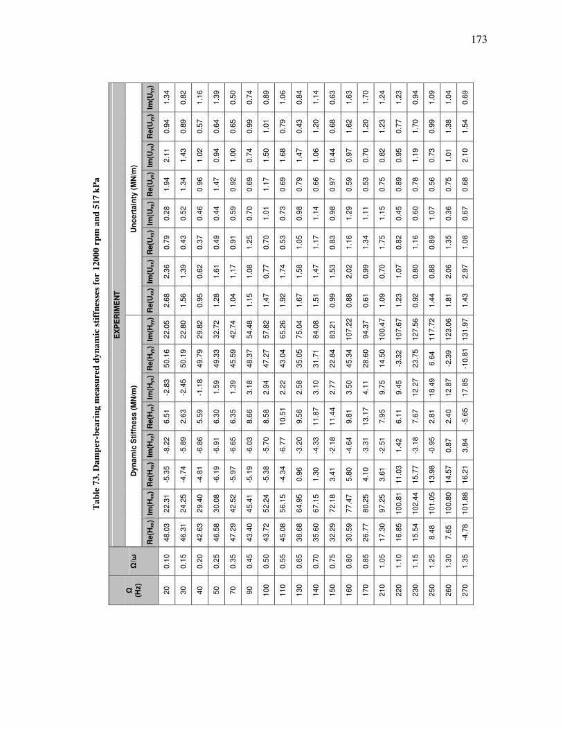
173
Ta
ble
73
. D
am
per
-bea
rin
g m
easu
red
dy
na
mic
sti
ffn
esse
s fo
r 1
200
0 r
pm
an
d 5
17 k
Pa
EX
PE
RIM
EN
T
Un
cert
ain
ty (
MN
/m)
Im(U
yy)
1.3
4
0.8
2
1.1
6
1.3
9
0.5
0
0.7
4
0.8
9
1.0
6
0.8
4
1.1
4
0.6
3
1.6
3
1.7
0
1.2
4
1.2
3
0.9
4
1.0
9
1.0
4
0.6
9
Re(U
yy)
0.9
4
0.8
9
0.5
7
0.6
4
0.6
5
0.9
9
1.0
1
0.7
9
0.4
3
1.2
0
0.6
8
1.6
2
1.2
0
1.2
3
0.7
7
1.7
0
0.9
9
1.3
8
1.5
4
Im(U
yx)
2.1
1
1.4
3
1.0
2
0.9
4
1.0
0
0.7
4
1.5
0
1.6
8
1.4
7
1.0
6
0.4
4
0.9
7
0.7
0
0.8
2
0.9
5
1.1
9
0.7
3
1.0
1
2.1
0
Re(U
yx)
1.9
4
1.3
4
0.9
6
1.4
7
0.9
2
0.6
9
1.1
7
0.6
9
0.7
9
0.6
6
0.9
7
0.5
9
0.5
3
0.7
5
0.8
9
0.7
8
0.5
6
0.7
5
0.6
8
Im(U
xy)
0.2
8
0.5
2
0.4
6
0.4
4
0.5
9
0.7
0
1.0
1
0.7
3
0.9
8
1.1
4
0.9
8
1.2
9
1.1
1
1.1
5
0.4
5
0.6
0
1.0
7
0.3
6
0.6
7
Re(U
xy)
0.7
9
0.4
3
0.3
7
0.4
9
0.9
1
1.2
5
0.7
0
0.5
3
1.0
5
1.1
7
0.8
3
1.1
6
1.3
4
1.7
5
0.8
2
1.1
6
0.8
9
1.3
5
1.0
8
Im(U
xx)
2.3
6
1.3
9
0.6
2
1.6
1
1.1
7
1.0
8
0.7
7
1.7
4
1.5
8
1.4
7
1.5
3
2.0
2
0.9
9
0.7
0
1.0
7
0.8
0
0.8
8
2.0
6
2.9
7
Re(U
xx)
2.6
8
1.5
6
0.9
5
1.2
8
1.0
4
1.1
5
1.4
7
1.9
2
1.6
7
1.5
1
0.9
9
0.8
8
0.6
1
1.0
9
1.2
3
0.9
2
1.4
4
1.8
1
1.4
3
Dyn
am
ic S
tiff
ness (
MN
/m)
Im(H
yy)
22.0
5
22.8
0
29.8
2
32.7
2
42.7
4
54.4
8
57.8
2
65.2
6
75.0
4
84.0
8
83.2
1
107.2
2
94.3
7
100.4
7
107.6
7
127.5
6
117.7
2
123.0
6
131.9
7
Re(H
yy)
50.1
6
50.1
9
49.7
9
49.3
3
45.5
9
48.3
7
47.2
7
43.0
4
35.0
5
31.7
1
22.8
4
45.3
4
28.6
0
14.5
0
-3.3
2
23.7
5
6.6
4
-2.3
9
-10.8
1
Im(H
yx)
-2.8
3
-2.4
5
-1.1
8
1.5
9
1.3
9
3.1
8
2.9
4
2.2
2
2.5
8
3.1
0
2.7
7
3.5
0
4.1
1
9.7
5
9.4
5
12.2
7
18.4
9
12.8
7
17.8
5
Re(H
yx)
6.5
1
2.6
3
5.5
9
6.3
0
6.3
5
8.6
6
8.5
8
10.5
1
9.5
6
11.8
7
11.4
4
9.8
1
13.1
7
7.9
5
6.1
1
7.6
7
2.8
1
2.4
0
-5.6
5
Im(H
xy)
-8.2
2
-5.8
9
-6.8
6
-6.9
1
-6.6
5
-6.0
3
-5.7
0
-6.7
7
-3.2
0
-4.3
3
-2.1
8
-4.6
4
-3.3
1
-2.5
1
1.4
2
-3.1
8
-0.9
5
0.8
7
3.8
4
Re(H
xy)
-5.3
5
-4.7
4
-4.8
1
-6.1
9
-5.9
7
-5.1
9
-5.3
8
-4.3
4
0.9
6
1.3
0
3.4
1
5.8
0
4.1
0
3.6
1
11.0
3
15.7
7
13.9
8
14.5
7
16.2
1
Im(H
xx)
22.3
1
24.2
5
29.4
0
30.0
8
42.5
2
45.4
1
52.2
4
56.1
5
64.9
5
67.1
5
72.1
8
77.4
7
80.2
5
97.2
5
100.8
1
102.4
4
101.0
5
100.8
0
101.8
8
Re(H
xx)
48.0
3
46.3
1
42.6
3
46.5
8
47.2
9
43.4
0
43.7
2
45.0
8
38.6
8
35.6
0
32.2
9
30.5
9
26.7
7
17.3
0
16.8
5
15.5
4
8.4
8
7.6
5
-4.7
8
Ω/ω
0.1
0
0.1
5
0.2
0
0.2
5
0.3
5
0.4
5
0.5
0
0.5
5
0.6
5
0.7
0
0.7
5
0.8
0
0.8
5
1.0
5
1.1
0
1.1
5
1.2
5
1.3
0
1.3
5
Ω
(Hz)
20
30
40
50
70
90
100
110
130
140
150
160
170
210
220
230
250
260
270
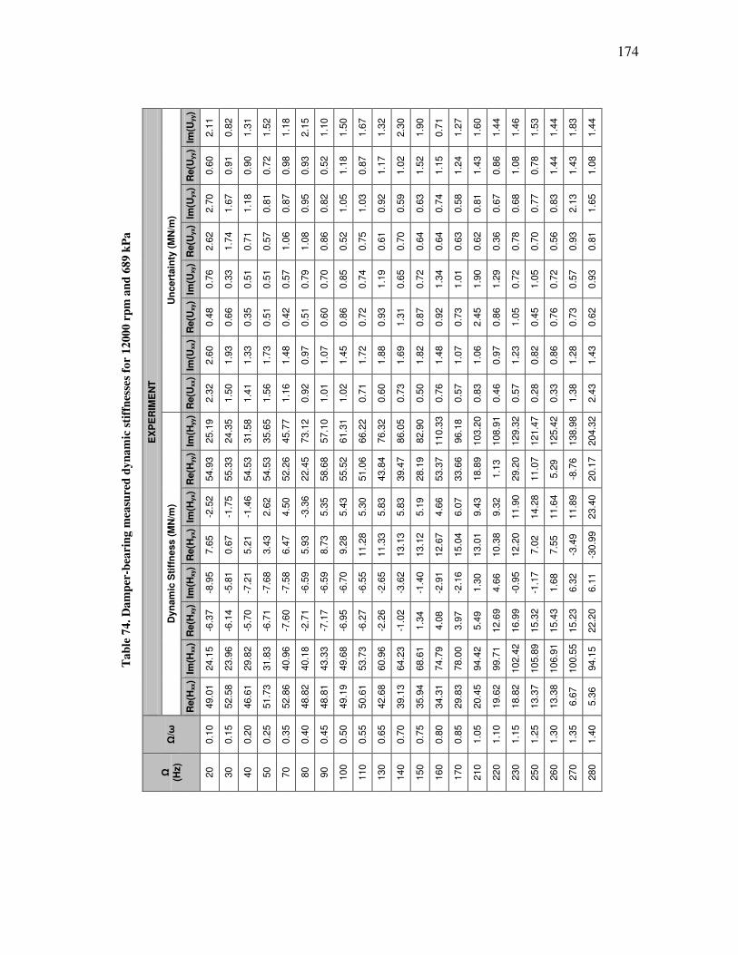
174
Ta
ble
74
. D
am
per
-bea
rin
g m
easu
red
dy
na
mic
sti
ffn
esse
s fo
r 1
200
0 r
pm
an
d 6
89 k
Pa
EX
PE
RIM
EN
T
Un
cert
ain
ty (
MN
/m)
Im(U
yy)
2.1
1
0.8
2
1.3
1
1.5
2
1.1
8
2.1
5
1.1
0
1.5
0
1.6
7
1.3
2
2.3
0
1.9
0
0.7
1
1.2
7
1.6
0
1.4
4
1.4
6
1.5
3
1.4
4
1.8
3
1.4
4
Re(U
yy)
0.6
0
0.9
1
0.9
0
0.7
2
0.9
8
0.9
3
0.5
2
1.1
8
0.8
7
1.1
7
1.0
2
1.5
2
1.1
5
1.2
4
1.4
3
0.8
6
1.0
8
0.7
8
1.4
4
1.4
3
1.0
8
Im(U
yx)
2.7
0
1.6
7
1.1
8
0.8
1
0.8
7
0.9
5
0.8
2
1.0
5
1.0
3
0.9
2
0.5
9
0.6
3
0.7
4
0.5
8
0.8
1
0.6
7
0.6
8
0.7
7
0.8
3
2.1
3
1.6
5
Re(U
yx)
2.6
2
1.7
4
0.7
1
0.5
7
1.0
6
1.0
8
0.8
6
0.5
2
0.7
5
0.6
1
0.7
0
0.6
4
0.6
4
0.6
3
0.6
2
0.3
6
0.7
8
0.7
0
0.5
6
0.9
3
0.8
1
Im(U
xy)
0.7
6
0.3
3
0.5
1
0.5
1
0.5
7
0.7
9
0.7
0
0.8
5
0.7
4
1.1
9
0.6
5
0.7
2
1.3
4
1.0
1
1.9
0
1.2
9
0.7
2
1.0
5
0.7
2
0.5
7
0.9
3
Re(U
xy)
0.4
8
0.6
6
0.3
5
0.5
1
0.4
2
0.5
1
0.6
0
0.8
6
0.7
2
0.9
3
1.3
1
0.8
7
0.9
2
0.7
3
2.4
5
0.8
6
1.0
5
0.4
5
0.7
6
0.7
3
0.6
2
Im(U
xx)
2.6
0
1.9
3
1.3
3
1.7
3
1.4
8
0.9
7
1.0
7
1.4
5
1.7
2
1.8
8
1.6
9
1.8
2
1.4
8
1.0
7
1.0
6
0.9
7
1.2
3
0.8
2
0.8
6
1.2
8
1.4
3
Re(U
xx)
2.3
2
1.5
0
1.4
1
1.5
6
1.1
6
0.9
2
1.0
1
1.0
2
0.7
1
0.6
0
0.7
3
0.5
0
0.7
6
0.5
7
0.8
3
0.4
6
0.5
7
0.2
8
0.3
3
1.3
8
2.4
3
Dyn
am
ic S
tiff
ness (
MN
/m)
Im(H
yy)
25.1
9
24.3
5
31.5
8
35.6
5
45.7
7
73.1
2
57.1
0
61.3
1
66.2
2
76.3
2
86.0
5
82.9
0
110.3
3
96.1
8
103.2
0
108.9
1
129.3
2
121.4
7
125.4
2
138.9
8
204.3
2
Re(H
yy)
54.9
3
55.3
3
54.5
3
54.5
3
52.2
6
22.4
5
58.6
8
55.5
2
51.0
6
43.8
4
39.4
7
28.1
9
53.3
7
33.6
6
18.8
9
1.1
3
29.2
0
11.0
7
5.2
9
-8.7
6
20.1
7
Im(H
yx)
-2.5
2
-1.7
5
-1.4
6
2.6
2
4.5
0
-3.3
6
5.3
5
5.4
3
5.3
0
5.8
3
5.8
3
5.1
9
4.6
6
6.0
7
9.4
3
9.3
2
11.9
0
14.2
8
11.6
4
11.8
9
23.4
0
Re(H
yx)
7.6
5
0.6
7
5.2
1
3.4
3
6.4
7
5.9
3
8.7
3
9.2
8
11.2
8
11.3
3
13.1
3
13.1
2
12.6
7
15.0
4
13.0
1
10.3
8
12.2
0
7.0
2
7.5
5
-3.4
9
-30.9
9
Im(H
xy)
-8.9
5
-5.8
1
-7.2
1
-7.6
8
-7.5
8
-6.5
9
-6.5
9
-6.7
0
-6.5
5
-2.6
5
-3.6
2
-1.4
0
-2.9
1
-2.1
6
1.3
0
4.6
6
-0.9
5
-1.1
7
1.6
8
6.3
2
6.1
1
Re(H
xy)
-6.3
7
-6.1
4
-5.7
0
-6.7
1
-7.6
0
-2.7
1
-7.1
7
-6.9
5
-6.2
7
-2.2
6
-1.0
2
1.3
4
4.0
8
3.9
7
5.4
9
12.6
9
16.9
9
15.3
2
15.4
3
15.2
3
22.2
0
Im(H
xx)
24.1
5
23.9
6
29.8
2
31.8
3
40.9
6
40.1
8
43.3
3
49.6
8
53.7
3
60.9
6
64.2
3
68.6
1
74.7
9
78.0
0
94.4
2
99.7
1
102.4
2
105.8
9
106.9
1
100.5
5
94.1
5
Re(H
xx)
49.0
1
52.5
8
46.6
1
51.7
3
52.8
6
48.8
2
48.8
1
49.1
9
50.6
1
42.6
8
39.1
3
35.9
4
34.3
1
29.8
3
20.4
5
19.6
2
18.8
2
13.3
7
13.3
8
6.6
7
5.3
6
Ω/ω
0.1
0
0.1
5
0.2
0
0.2
5
0.3
5
0.4
0
0.4
5
0.5
0
0.5
5
0.6
5
0.7
0
0.7
5
0.8
0
0.8
5
1.0
5
1.1
0
1.1
5
1.2
5
1.3
0
1.3
5
1.4
0
Ω
(Hz)
20
30
40
50
70
80
90
100
110
130
140
150
160
170
210
220
230
250
260
270
280

175
Ta
ble
75
. D
am
per
-bea
rin
g m
easu
red
dy
na
mic
sti
ffn
esse
s fo
r 1
200
0 r
pm
an
d 8
62 k
Pa
EX
PE
RIM
EN
T
Un
cert
ain
ty (
MN
/m)
Im(U
yy)
1.5
4
1.2
8
1.6
9
1.4
4
1.2
2
0.9
7
1.2
7
1.2
4
1.6
1
1.5
5
2.1
9
2.5
9
2.3
1
3.3
1
5.7
0
2.9
6
3.8
9
1.8
5
1.2
1
1.2
9
1.4
9
Re(U
yy)
1.1
5
0.9
4
0.8
6
0.8
3
0.7
6
0.5
1
1.0
2
1.4
1
1.0
4
0.9
2
1.0
0
0.6
8
2.1
5
2.7
5
2.6
5
2.0
5
2.3
3
2.0
8
2.7
9
2.9
3
5.1
3
Im(U
yx)
4.6
9
1.3
0
1.5
1
1.9
1
1.7
2
1.0
2
1.0
4
0.8
1
0.6
9
0.9
6
0.9
4
1.1
8
1.5
6
1.4
3
0.9
5
0.7
0
0.7
2
0.2
6
0.4
9
0.6
7
2.4
1
Re(U
yx)
3.3
2
1.3
0
2.4
9
1.5
9
1.2
7
1.1
7
1.0
5
1.1
5
1.1
3
0.8
9
1.2
5
0.9
7
1.0
4
0.7
8
2.0
5
0.9
2
1.1
9
1.3
0
1.2
0
1.9
0
2.4
1
Im(U
xy)
0.4
9
0.7
6
0.6
5
0.6
5
0.9
3
0.8
0
0.6
5
0.9
6
1.0
5
0.9
3
0.9
0
0.9
9
1.8
7
1.8
6
2.7
2
1.4
4
1.3
2
0.9
4
0.7
4
0.7
9
1.0
4
Re(U
xy)
0.4
9
0.5
0
0.8
7
0.7
1
0.8
3
0.7
8
0.9
6
1.3
7
1.1
4
1.1
4
1.3
1
1.5
8
2.3
9
2.8
0
5.6
3
2.8
9
1.7
6
1.2
6
0.8
3
1.1
4
0.6
0
Im(U
xx)
3.8
4
2.1
0
2.1
9
2.0
1
1.3
5
0.9
7
1.4
5
1.7
1
1.4
1
1.5
0
1.8
5
1.4
0
1.4
9
1.9
3
1.4
8
1.0
9
1.0
2
0.9
0
1.0
7
1.1
7
0.9
1
Re(U
xx)
3.5
4
1.2
5
0.7
7
1.7
2
1.1
5
1.0
8
1.5
5
2.3
5
1.3
2
1.8
8
1.4
2
1.6
4
1.8
8
2.3
3
1.5
9
0.9
6
1.5
7
1.3
6
1.2
0
1.6
9
0.6
9
Dyn
am
ic S
tiff
ness (
MN
/m)
Im(H
yy)
29.6
6
31.3
6
40.3
8
45.3
9
59.2
1
73.4
2
76.8
3
83.2
3
91.1
2
106.4
1
117.0
3
110.5
2
140.4
4
126.0
6
135.9
1
139.2
4
167.0
7
154.8
4
159.0
5
170.0
0
257.8
7
Re(H
yy)
60.1
4
61.7
4
60.4
6
60.0
6
57.4
0
33.0
5
63.2
4
60.0
3
56.7
8
51.6
5
46.2
7
37.1
2
64.3
0
42.5
9
30.6
4
16.0
0
44.8
8
23.0
3
20.5
2
-2.9
8
18.1
2
Im(H
yx)
-1.4
6
-1.0
8
-1.4
7
3.0
2
4.2
1
1.1
3
4.9
5
3.7
3
4.5
2
4.5
6
5.0
8
5.9
0
6.0
4
7.0
1
9.4
7
10.5
6
15.2
3
17.7
9
16.1
4
15.0
8
29.7
4
Re(H
yx)
4.6
9
2.0
0
5.0
2
5.5
2
8.1
1
10.6
9
10.9
5
9.2
9
11.7
8
11.4
3
14.0
6
13.9
7
14.5
3
17.2
4
17.1
6
13.1
9
15.8
8
10.5
3
11.0
2
3.7
3
-22.1
2
Im(H
xy)
-6.9
6
-4.4
7
-5.3
9
-5.2
2
-3.4
2
-0.9
6
-2.0
7
-2.1
6
-2.8
3
-1.0
8
-2.3
8
-0.3
1
-3.6
6
-0.6
2
-0.9
4
1.1
1
-4.6
2
-3.8
4
-3.3
8
1.2
6
-2.1
1
Re(H
xy)
-5.1
7
-4.8
0
-4.8
7
-5.1
4
-4.7
5
-0.4
3
-0.6
6
0.3
1
2.8
9
9.7
7
11.0
3
11.8
1
15.9
3
14.9
0
15.5
6
22.2
2
29.2
6
26.6
0
26.9
1
26.3
2
36.3
9
Im(H
xx)
23.9
3
25.1
9
33.3
9
39.4
4
48.8
2
52.4
1
55.6
4
64.6
6
70.8
2
80.9
0
84.3
5
87.6
0
94.3
2
97.9
4
115.1
3
122.1
0
124.4
2
128.3
3
129.9
1
124.8
2
122.6
2
Re(H
xx)
54.3
5
51.3
1
49.2
7
53.5
5
54.9
0
51.0
5
52.6
1
53.0
2
53.0
8
46.3
1
46.1
9
43.5
5
43.1
9
38.3
5
27.5
8
27.0
3
27.4
4
22.7
5
22.1
9
19.4
7
26.0
7
Ω/ω
0.1
0
0.1
5
0.2
0
0.2
5
0.3
5
0.4
0
0.4
5
0.5
0
0.5
5
0.6
5
0.7
0
0.7
5
0.8
0
0.8
5
1.0
5
1.1
0
1.1
5
1.2
5
1.3
0
1.3
5
1.4
0
Ω
(Hz)
20
30
40
50
70
80
90
100
110
130
140
150
160
170
210
220
230
250
260
270
280
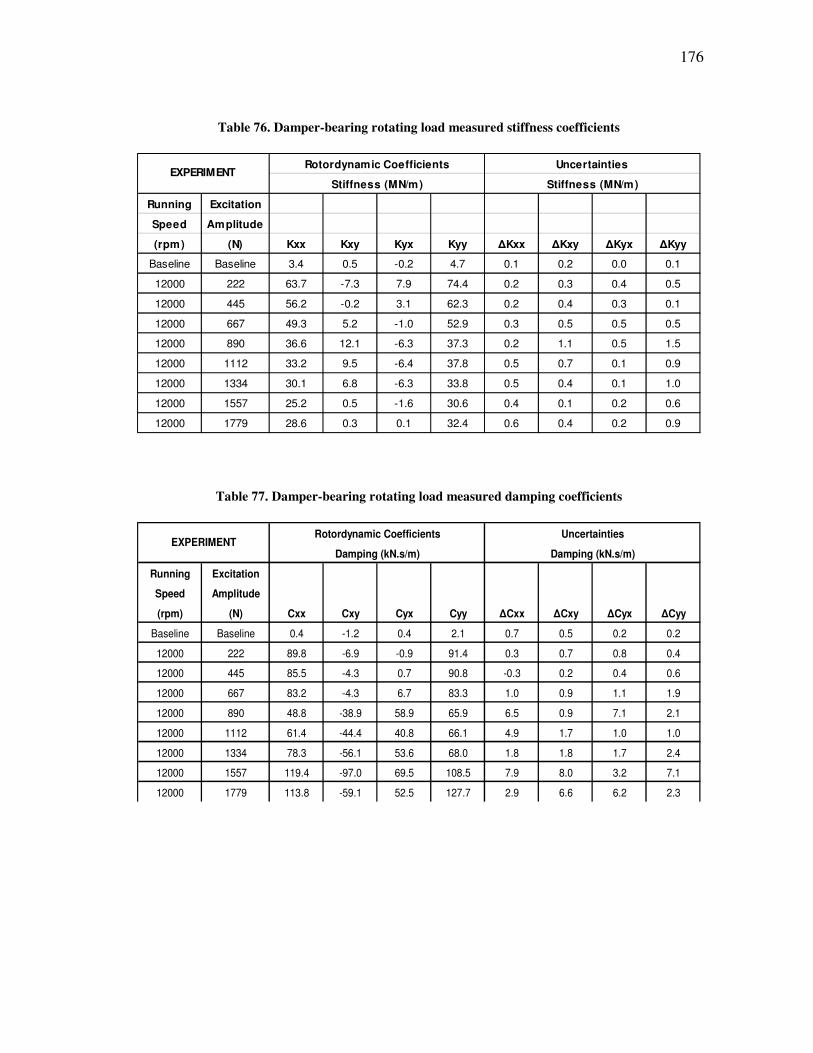
176
Table 76. Damper-bearing rotating load measured stiffness coefficients
Rotordynamic Coefficients Uncertainties
Stiffness (MN/m) Stiffness (MN/m)
Running Excitation
Speed Amplitude
(rpm) (N) Kxx Kxy Kyx Kyy ∆Kxx ∆Kxy ∆Kyx ∆Kyy
Baseline Baseline 3.4 0.5 -0.2 4.7 0.1 0.2 0.0 0.1
12000 222 63.7 -7.3 7.9 74.4 0.2 0.3 0.4 0.5
12000 445 56.2 -0.2 3.1 62.3 0.2 0.4 0.3 0.1
12000 667 49.3 5.2 -1.0 52.9 0.3 0.5 0.5 0.5
12000 890 36.6 12.1 -6.3 37.3 0.2 1.1 0.5 1.5
12000 1112 33.2 9.5 -6.4 37.8 0.5 0.7 0.1 0.9
12000 1334 30.1 6.8 -6.3 33.8 0.5 0.4 0.1 1.0
12000 1557 25.2 0.5 -1.6 30.6 0.4 0.1 0.2 0.6
12000 1779 28.6 0.3 0.1 32.4 0.6 0.4 0.2 0.9
EXPERIMENT
Table 77. Damper-bearing rotating load measured damping coefficients
Rotordynamic Coefficients Uncertainties
Damping (kN.s/m) Damping (kN.s/m)
Running Excitation
Speed Amplitude
(rpm) (N) Cxx Cxy Cyx Cyy ∆Cxx ∆Cxy ∆Cyx ∆Cyy
Baseline Baseline 0.4 -1.2 0.4 2.1 0.7 0.5 0.2 0.2
12000 222 89.8 -6.9 -0.9 91.4 0.3 0.7 0.8 0.4
12000 445 85.5 -4.3 0.7 90.8 -0.3 0.2 0.4 0.6
12000 667 83.2 -4.3 6.7 83.3 1.0 0.9 1.1 1.9
12000 890 48.8 -38.9 58.9 65.9 6.5 0.9 7.1 2.1
12000 1112 61.4 -44.4 40.8 66.1 4.9 1.7 1.0 1.0
12000 1334 78.3 -56.1 53.6 68.0 1.8 1.8 1.7 2.4
12000 1557 119.4 -97.0 69.5 108.5 7.9 8.0 3.2 7.1
12000 1779 113.8 -59.1 52.5 127.7 2.9 6.6 6.2 2.3
EXPERIMENT

177
Table 78. Damper-bearing rotating load measured added mass coefficients
Rotordynamic Coefficients Uncertainties
Added Mass (kg) Added Mass (kg)
Running Excitation
Speed Amplitude
(rpm) (N) Mxx Mxy Myx Myy ∆Mxx ∆Mxy ∆Myx ∆Myy
Baseline Baseline 4.9 0.5 1.1 4.4 0.6 0.6 0.2 0.2
12000 222 46.0 10.2 -14.6 38.7 -0.1 0.1 1.6 0.9
12000 445 35.5 10.9 -12.5 30.0 -0.2 0.1 0.1 0.8
12000 667 27.6 11.2 -7.7 29.2 0.0 2.7 0.6 2.0
12000 890 40.1 -35.4 -0.2 95.0 0.3 9.9 0.9 9.7
12000 1112 42.8 -16.7 1.6 62.8 0.9 7.6 0.6 1.1
12000 1334 49.8 11.0 -1.0 77.0 0.6 3.1 1.6 2.3
12000 1557 97.8 72.5 -50.1 105.9 6.8 11.5 6.6 6.6
12000 1779 57.7 71.4 -77.1 89.4 10.5 4.3 3.3 9.1
EXPERIMENT
178
VITA
Name: Jeffrey Scott Agnew
Address: P.O. Box 44, Tonawanda, NY 14151-0044
Email Address: [email protected]
Education: B.S., Mechanical Engineering, Arkansas State University, 2006
M.S., Mechanical Engineering, Texas A&M University, 2011