rotor blade
TRANSCRIPT

NASA Contractor Report 166525 I
I UTRC Report R84-915774-24
Analytic Investigation of Helicopter Rotor Blade Appended Aeroelas tic Devices
Richard L. Bielawa United Technologies Research Center EastHartfond, CT m1iN
Prepared for Ames Research Center under Contract NASZ-11008
T National Aeronautics and Space Administration Amas Research Center Moftett Field. California 94035

PREFACE
The resul ts described he re in were performed by United Technologies Research Center (UTRC) under c o n t r a c t NAS2-11008, "Analytic I n v e s t i g a t i o n of Hel icopter Rotor Blade Appended Aeroe la s t i c Devices.'' through the Ames Research Center of NASA with M r . Robert H. Stroub a c t i n g a s c o n t r a c t monitor. The program manager f o r t h i s s t u d y was D r . Richard L . Bielawa. The s t u d y made ex tens ive use of the GOOOPA a e r o e l a s t i c a n a l y s i s developed by UTRC f o r NASA Langley Research Center and the S t r u c t u r e s Laboratory of the USRTL (AVRADCOM) under con t r ac t NAS1-16058.
This con t r ac t was
PRWlZDPIG PAGE BLANK NOT wG13

TABLE OF CONTEXTS
PREFACE
LIST OF FIGURES AKD TABLES
SUMMARY J
INTRODUCTION Background Description of Aeroelastic Devices Analysis Requirements
LIST OF SYMBOLS
MATHEMATICAL DEV ELOPMEKT Torsionally Active Devices Harmonically Dilational Airfoil Tip
RESULTS Baseline Rotor Configuration Trimmed Flight Conditions Passive Tuned Tab Control Coupled Tab All-Flying Torsion Tip Harmonically Dilational Airfoil Tip
CONCLUSIONS AND RECOMMENDATIONS
REFERENCES
PRECEDING PAGE BLANK NOT m&X?
Page i ii
vii
1 1 3 14
17
2 3 2 3 51
3 7 37 37 47 55 58 81
85
89

L I S T OF FIGURES AXD TABLES
Figure No. T i t l e
1. P i c t o r i a l of Tuned Tra i l i ng Edge Tab
2.
3. P i c t o r i a l of All-Flying Torsion Tip
P i c t o r i d of T r a i l i n g Edge Tab Coupled t o Blade Control Loads
4 . P i c t o r i a l of Hel icopter Rotor Disk i n Forward F l i g h t Showing Conf l i c t ing Requirements f o r Blade Tip Sec t ions
5 . P i c t o r i a l of Harmonically Deformable A i r f o i l Tip
6. Geometrical and Mechanical Modeling of t he Tors iona l ly Active Devices
7 . Schematic of Exc i t a t ion Scheme f o r Harmonically Deformable A i r f o i l Tip
8 . Spanwise Var i a t ion of 1/2PTP Fla twise Bending Moment f o r Trimmed Basel ine Cases
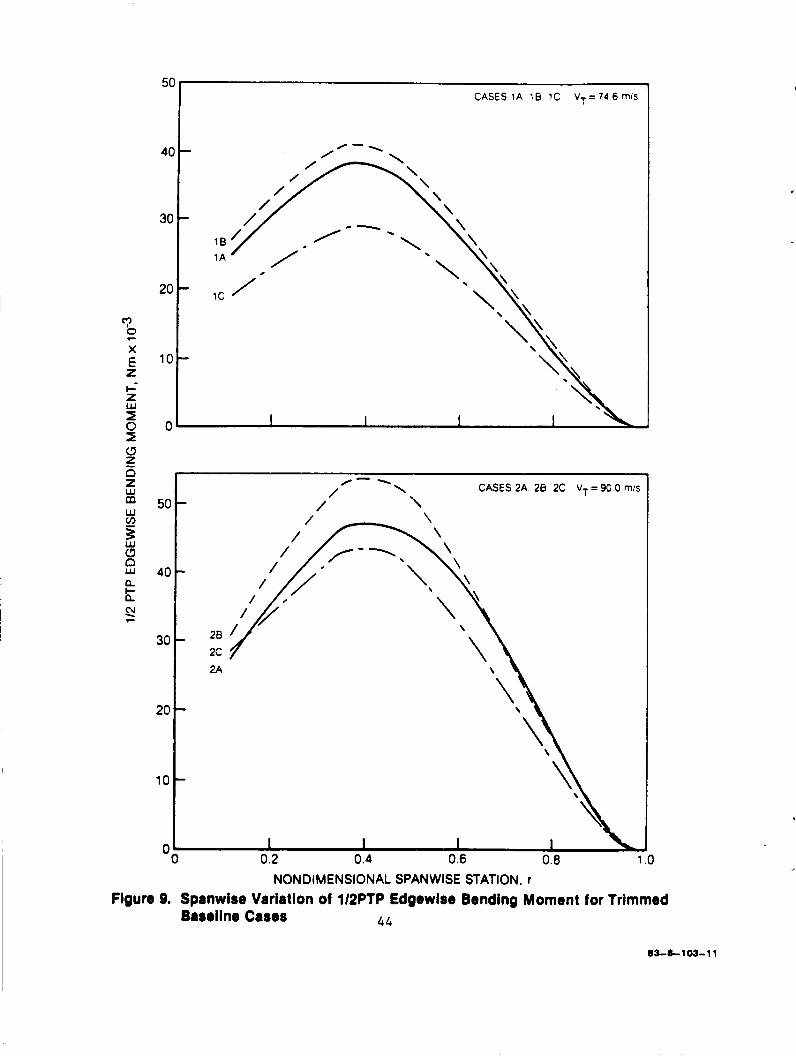
9. Spanwise Var i a t ion of 1/2PTP Edgewise Bending Moment f o r Trimmed Basel ine Cases
10. Spanwise Var i a t ion of 4P Fla twise Bending Moment f o r Trimmed Basel ine Cases
11. Spanwise Var i a t ion of 4P Edgewise Bending Moment f o r Trimmed Baseline Cases
12. S impl i f ied Conceptual izat ion of t h e Pass ive Tuned Tab
13. R e s u l t s of S impl i f ied Analysis--Effect of Pass ive Tab Spanwise Location on Root Vertical Shears , p 0 . 4 , C /0=.09
T
14. Var i a t ions i n Components of 4P Hub Shear w i t h Pass ive Tuned Tab Mass, 90 m / s F l i g h t Speed ( ~ 0 . 4 )
15. Var ia t ions i n Components of 4P Hub Shear w i th Pass ive Tuned Tab Uncoupled Tab Frequency, 90 m/s F l i g h t Speed (v-0.407)
Page
5
7
9
11
12
2 5
33
43
44
45
46
48
49
52
53
PRECEDING PAGE BLANK NOT FWE@
LIST OF FIGURES AND TABLES cont inued
Figure No. T i t l e Page
16. Var ia t ions i n Components of 4P Hub Shear with Passive 5 4 Tuned Tab Mass Center Location, 90 m / s F l i g h t Speed (p -0 .4 )
1 7 . Ef fec t of Offse t Moment and Spring Rate on Operation of All-Flying T i p - Prel iminary A n a l y s i s
60
18. Ef fec t of Linear ly Combined Offse t Moment and Spring Rate on Equilibrium Loading Moment f o r All-Flying Tip - Prel iminary Analysis
61
19. Var ia t ion of LID, with Spring Rate f o r All-Flying Tip - Prel iminary Analysis
62
20. Comparison of L/D, C h a r a c t e r i s t i c s of All-Flying Tip Using 65 Quasi-Static v s . Unsteady A i r l o a d s Formulations, 90.0 m / s F l i g h t Speed (u=0.407), 0.15R Tip Span.
21. Comparison of Equilibrium Moment C h a r a c t e r i s t i c s f o r All- 67 Flying T i p Using Al t e rna te Applied Moments, 90 m/s F l i g h t Speed (v=0.407) , 0.10R T i p Span
22. Comparison of L/De C h a r a c t e r i s t i c s of All-Flying Tip Using 68 Al t e rna te Offset Moment Schedules, 1~10.407, 0.10R Tip Span
23. Comparison of Equilibrium Moment C h a r a c t e r i s t i c s of 69 All-Flying Tip f o r Alternate F l i g h t Speeds and Tip Spans
24. Comparison of L/De Characteristics of All-Flying Tip f o r 70 Al t e rna te F l i g h t Speeds and Tip Spans
25. Time-History Responses of All-Flying Tip f o r Alternate Spring Rates, 0.15R Tip Span, ~0.407
71
v i i i

LIST OF FIGURES A?D TABLES cont inued
I .
I -
Figure No. Title
26,
27,
28.
29.
30.
31.
32.
33.
34 .
Time-History Responses of All-Flying Tip for Alternate Spring Rates, 0.10R Tip Span, ~ 0 . 4 0 7
Variation of Time-History Responses of All-Flying Tip with Flight Speed, Maximum L/De Configuration, 0.15R Tip Span
Variation of Time-History Responses of All-Flying Tip with Flight Speed, Maximum L/De Configuration, 0.10R Tip Span
Angle-of-Attack Time-Histories at r = 0.925R for All- Flying Tip, Maximum L/De Configuration, 0.15R Tip Span, PO. 338
Angle-of-Attack Time-Histories at r = 0.925R for All- Flying Tip, Maximum L/De Configuration, 0.15R Tip Span, p=0.407
Vibratory Blade Bending and Torsion Moment Charac- teristics for All-Flying Tip, 0.15R Tip Span, p=O. 338, Maximum L/De Conditions
Vibratory Blade Bending and Torsion Moment Charac- teristics for All-Flying Tip, 0.15R Tip Span, u-0.407, Maximum L/De Conditions
Variation of L/De Characteristics of Harmonically Dilational Tip with Amplitude of Perturbational Thickness Ratio, 0.15R Tip Span, p-0.407.
Comparison of L/De Characteristics of Harmonically Dilational Tip for Variations in Flight Speed and Tip Span
Page
7 2
7 3
7 4
76
7 7
79
80
8 3
84

TABLES
Table No. Title Page
I. Baseline (UH-60A) Rotor Blade Physical Parameters 38
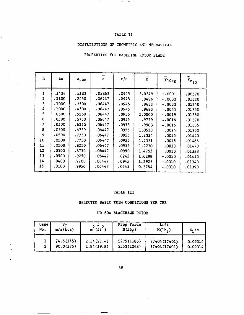
11. Distributions of Geometric and Mechanical Properties for Baseline Rotor Blade
111. Selected Basic Trim Conditions for the UH-60A Blackhawk Rotor
IV . Summary of GOOOPA Trim Calculations Achieved for UH-60A Blackhawk Rotor
39
39
4 2
V. Partial Derivatives of Performance Parameters with Respect 56 to Coupling Gain for Control Coupled Tab, ~'0.338
X
--
AXALYTIC IhT'ESTIGATIOK OF HELICOPTER ROTOR
BLADE APPENDED AEROELASTIC DEVICES
By Richard L. Bielawa United Technologies Research Center
SUMMARY
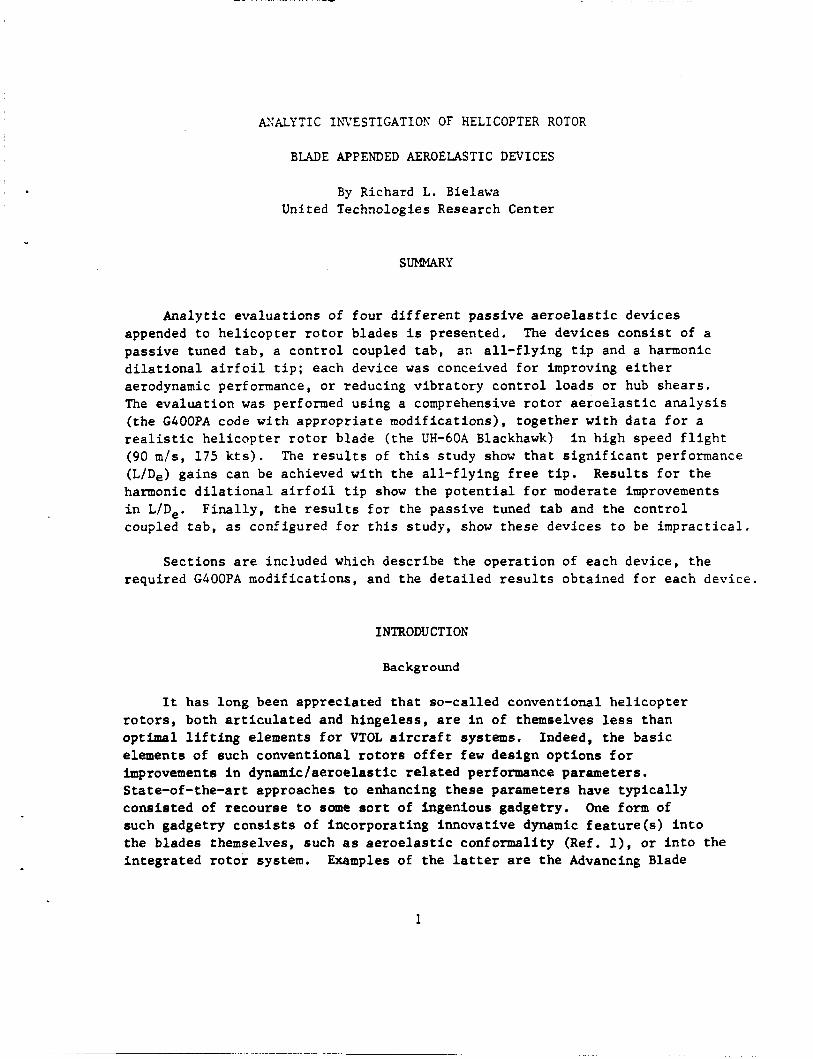
Analyt ic eva lua t ions of fou r d i f f e r e n t pas s ive a e r o e l a s t i c devices appended t o h e l i c o p t e r r o t o r blades i s presented. The devices c o n s i s t of a passive tuned t a b , a c o n t r o l coupled t a b , an a l l - f l y i n g t i p and a harmonic d i l a t i o n a l a i r f o i l t i p ; each device was conceived f o r improving e i t h e r aerodynamic performance, o r reducing v ib ra to ry c o n t r o l l oads o r hub shea r s . The eva lua t ion was performed using a comprehensive r o t o r a e r o e l a s t i c analysis ( the G400PA code with appropr i a t e mod i f i ca t ions ) , t oge the r w i t h d a t a f o r a r e a l i s t i c h e l i c o p t e r r o t o r blade ( the UH-60A Blackhawk) i n high speed f l i g h t (90 m / s , 175 k t s ) . The r e s u l t s of t h i s study show t h a t s i g n i f i c a n t performance (L/De) ga ins can be achieved with t h e a l l - f l y i n g f r e e t i p . harmonic d i l a t i o n a l a i r f o i l t i p show t h e p o t e n t i a l f o r moderate improvements i n LID,. coupled tab , as configured f o r t h i s s t u d y , show these devices t o be imprac t i ca l .
Resu l t s f o r t he
F i n a l l y , t he r e s u l t s f o r the passive tuned t a b and the c o n t r o l
Sect ions are included which descr ibe the ope ra t ion of each device, t he required GOOOPA modif icat ions, and the d e t a i l e d r e s u l t s obtained f o r each device.
I NTRODU CT I ON
Background
It has long been appreciated t h a t so-called conventional h e l i c o p t e r r o t o r s , both a r t i c u l a t e d and h inge le s s , are I n of themselves less than optimal l i f t i n g elements f o r VTOL a i r c r a f t systems. Indeed, t he b a s i c elements of such conventional r o t o r s o f f e r few design op t ions f o r improvements i n dynamlc/aeroelast ic r e l a t e d performance parameters. State-of-the-art approaches t o enhancing t h e s e parameters have t y p i c a l l y cons i s t ed of recourse t o some s o r t of ingenious gadgetry. such gadgetry c o n s i s t s of i nco rpora t ing innovat ive dynamic f e a t u r e ( s ) i n t o the blades themselves, such as a e r o e l a s t i c conformality (Ref. l), or i n t o the i n t e g r a t e d r o t o r system.
One form of
Examples of t he l a t te r are t h e Advancing Blade
1

Concept (Ref.2) o r the t i l t - r o t o r concept (Ref . 3). A second form of gadgetry c o n s i s t s of t h e appending of a s p e c i a l i z e d aeromechanical device t o an otherwise conventional (or i t se l f a e r o e l a s t i c a l l y enhanced) r o t o r blade. The p resen t emergence of high performance, high s t r e n g t h m a t e r i a l s , t oge the r w i th an improved a b i l i t y t o analyze and understand the physics involved have made the implementations of such devices more a t t r a c t i v e as design s o l u t i o n s .
An example of a r o t o r blade appended mechanical device which can be r e a d i l y assumed t o be s ta te-of- the-ar t is the blade pendular absorber (Ref . 4 ) . The blade pendular absorber is cha rac t e r i zed by being a purely dynamic device with no d i r e c t aerodynamic i n t e r a c t i o n s and tuned t o ope ra t e a t n x r o t o r speed frequencies . v i b r a t i o n suppression device.
As such, t h e pendular absorber is i n h e r e n t l y only a pass ive
Other blade appended dynamic devices which do involve d i r e c t aerodynamic i n t e r a c t i o n have been conceived, bu t have not as y e t been subjected e i t h e r t o in-depth a n a l y s i s or experimental proof-of-concept. Reasons f o r t h i s l a c k of t e c h n i c a l underpinning would inc lude the l ack of a p p l i c a b i l i t y of s ta te-of- the- a r t production o r i en ted a n a l y s i s codes, and the d i f f i c u l t i e s i n designing and t e s t i n g workable experimental hardware. A meaningful a n a l y t i c a l s tudy of such devices would r equ i r e an apprec ia t ion of their germane c h a r a c t e r i s t i c s and the implementation of t hese c h a r a c t e r i s t i c s i n a proven comprehensive a e r o e l a s t i c a n a l y s i s of the type p r e s e n t l y used for state-of- the-ar t r o t o r systems.
The o b j e c t i v e of t h e p re sen t s tudy was, t h e r e f o r e , t o determine the p r a c t i c a l i t y , both a b s o l u t e and r e l a t i v e , of f o u r (4) d i f f e r e n t passive a e r o e l a s t i c devices appended t o h e l i c o p t e r r o t o r b l ades f o r improving r o t o r performance, c o n t r o l l oads and/or v i b r a t i o n a l l e v i a t i o n . It w a s bel ieved t h a t the fou r devices s e l e c t e d f o r t h i s study could o f f e r s i g n i f i c a n t p o t e n t i a l f o r achieving these improvements. s i g n i f i c a n t advance i n h e l i c o p t e r a e r o e l a s t i c s technology through the expres s s e l e c t i o n of only devices which are both pas s ive and a e r o e l a s t i c a l l y responsive.
It w a s hoped t h a t t h e s tudy might achieve a
The emphasis on p a s s i v i t y r e f l e c t s t h e d e s i r e t o achieve ga ins in performance, c o n t r o l l oads r educ t ion and v i b r a t i o n a l l e v i a t i o n through the s i m p l i c i t y afforded by fundamental r o t o r blade a e r o e l a s t i c responses i n forward f l i g h t . a t t r a c t i v e concepts f o r b l ade appended devices which u t i l i z e a c t i v e c o n t r o l schemes t o achieve t h e s e same improvements. complexity i n t h e form of a d d i t i o n a l e l e c t r o n i c s and/or hydrau l i c s which must u l t i m a t e l y r e s u l t i n i nc reased c o s t and less a t t r a c t i v e m a i n t a i n a b i l i t y and r e l i a b i l i t y c h a r a c t e r i s t i c s .
There undoubtedly ex is t equa l ly f e a s i b l e and p o t e n t i a l l y
However, active c o n t r o l imp l i e s
.
2
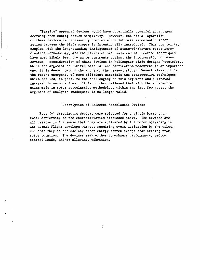
"Passive" appended devices would have p o t e n t i a l l y powerful advantages accruing from conf igu ra t ion s i m p l i c i t y . However, t he a c t u a l operat ion of these devices is n e c e s s a r i l y complex s i n c e in t ima te a e r o e l a s t i c i n t e r - a c t i o n between the blade proper i s i n t e n t i o n a l l y introduced, This complexity, eoupled with the long-standing inadequacies of s ta te-of- the-ar t r o t o r aero- e l a s t i c s methodology, and the l i m i t s of materials and f a b r i c a t i o n techniques have most l i k e l y been the major arguments a g a i n s t t he incorporat ion o r even s e r i o u s cons ide ra t ion of these devices i n h e l i c o p t e r blade designs he re to fo re . While t h e argument of l i m i t e d material and f a b r i c a t i o n resources i s an important one, i t is deemed beyond the scope of t h e p re sen t s tudy. Nevertheless, i t i s the r ecen t emergence of more e f f i c i e n t materials and cons t ruc t ion techniques which has l e d , i n p a r t , t o t he chal lenging of t h i s argument and a renewed i n t e r e s t i n such devices . It i s f u r t h e r bel ieved t h a t with the s u b s t a n t i a l ga ins made i n r o t o r a e r o e l a s t i c s methodology wi th in t h e l a s t few yea r s , t he argument of a n a l y s i s inadequacy is no longer v a l i d .
Descr ipt ion of Selected Aeroe la s t i c Devices
Four (4 ) a e r o e l a s t i c devices were s e l e c t e d f o r a n a l y s i s based upon t h e i r conformity t o t h e c h a r a c t e r i s t i c s discussed above. The devices a r e a l l passive i n the sense that they are a c t i v a t e d by t h e r o t o r ope ra t ing i n i ts normal f l i g h t envelope without r equ i r ing ove r t a c t i v a t i o n by the p i l o t , and t h a t they do no t use any other energy source except t h a t a r i s i n g from r o t o r r o t a t i o n . The devices seek e i t h e r t o enhance performance, reduce c o n t r o l loads, and/or a l l e v i a t e v i b r a t i o n .
3

1. Tuned T r a i l ing Edge Tab_
One scheme which could provide v i b r a t i o n a l l e v i a t i o n i s a Tuned (Tra i l i ng Edge) Tab concept. The o b j e c t i v e of t h i s t ab i s t o create harmonic a i r l o a d i n g of favorable amplitude and phase t o v e c t o r a l l y cancel the inherent harmonic a i r l o a d i n g which a c t s as a source of main r o t o r v i b r a t i o n .
.
A schematic of the pas s ive t a b concept i s shown i n Figure 1. P h y s i c a l l y , t h e pas s ive blade t a b i s appended near t o the t r a i l i n g edge of a s tandard r o t o r blade by some hinge conf igu ra t ion so t h a t t he t a b can d e f l e c t f r e e l y about t he hinge. or i t could be made of a composite material t h a t has a l a r g e s t r a i n a l lowable such t h a t t he t a b is a c t u a l l y "taped" t o the blade by t h e composite hinge. about the hinge would provide dynamic tuning c a p a b i l i t y ; t h e s p r i n g r a t e could be provided e i t h e r mechanically or by the e l a s t i c i ty of t he material f o r a composite hinge.
The hinge could be mechanical i n n a t u r e wi th bear ings, e t c . ,
The l a t i t u d e i n s e l e c t i n g t h e sp r ing ra te of t he t a b
The b a s i s of t he concept as ou t l ined i n Figure 1 i s simple: When a r o t o r blade t ab d e f l e c t s i t c r e a t e s an incremental a i r l o a d and p i t c h i n g moment on the r o t o r blade as a r e s u l t of t he increased camber. The p i t c h i n g moment a l s o c r e a t e s an a d d i t i o n a l a i r l o a d on the r o t o r blade by e l a s t i c t w i s t i n g t o create an incremental angle-of-attack. source of a i r l o a d i n g i s c l o s e l y t i e d t o the blade t o r s i o n a l s t i f f n e s s and na tu ra l frequency, t o t h a t obtained from t h e e f f e c t i v e camber change for t h i s concept. When the t a b d e f l e c t s harmonically, t he a i r l o a d s and p i t ch ing moment c rea t ed by the t a b d e f l e c t i o n are a l s o harmonic. Therefore, t o d e r i v e b e n e f i t from the t a b , the t a b motion m u s t be c o r r e c t l y phased t o cancel t h e inhe ren t harmonic a i r l o a d i n g t h a t excites the blade f l a t w i s e modes and produces v i b r a t i o n .
The importance of t h i s
This source of incremental a i r l o a d i n g i s secondary
The d r i v i n g f o r c e s on t h e t a b are i ts own i n e r t i a l loading as t h e blade f l a p s and p i t c h e s (both as a r i g i d body and f l e x i b l y ) and t h e aerodynamics a r i s i n g from blade and t a b motion. By inc reas ing the o f f s e t of t he t a b center of g r a v i t y from t h e hinge t h e i n e r t i a l f o r c i n g can be increased. For a t a b loca ted a t t h e blade t i p , most of t h e vertical harmonic motion would come from the response of t h e f l e x i b l e f l a t w i s e modes and nea r ly a l l of t h e t o r s i o n motion would be due t o t h e response of t h e blade f i rs t t o r s i o n mode. Hence, t h e r e is a d i r e c t r e l a t i o n s h i p between t h e motion t h a t i s i n e r t i a l l y fo rc ing t h e t a b t o d e f l e c t and t h e v i b r a t i o n t h a t i s a r e s u l t of that same motion. c o r r e c t l y s i z i n g and p l ac ing t h e t a b along t h e r o t o r blade span and choosing its mass and n a t u r a l frequency so t h a t t h e maximum v e c t o r a l c a n c e l l a t i o n of inherent harmonic a i r l o a d i n g is achieved.
Therefore, t h e success of t h i s concept hinges on
4

ALTERNATE IMPiEMENTATlON SCHEMES
MECHANICAL HINGE
COMPOSITE MATERIAL HINGE
Figure 1. Pictorial of Tuned Trailing Edge Tab
5

2. Tra i l ing Edge Tab Coupled t o Blade Control Loads
The s e l e c t i o n of a i r f o i l s f o r h e l i c o p t e r main r o t o r blades is l i m i t e d t o those a i r f o i l s which have low p i t ch ing moments because a i r f o i l s having high p i t ch ing moments cause excessive blade p i t c h c o n t r o l system v i b r a t o r y loads and high blade t o r s i o n a l d e f l e c t i o n s i n forward f l i g h t , of a i r f o i l s has t h e r e f o r e been constrained t o the use of symmetrical a i r f o i l s or a t b e s t , a i r f o i l s having 2 percent of camber. t h i s fundamental c o n s t r a i n t , h e l i c o p t e r maximum speeds are f r equen t ly l imi t ed by t h e r a p i d growth of v i b r a t o r y c o n t r o l loads as blade s t a l l i s approached, p a r t i c u l a r l y i n maneuvering f l i g h t . I f t hese c o n s t r a i n t s could be el iminated, a i r f o i l s w i th high camber could be employed and could be s e l e c t e d t o ope ra t e a t t h e i r optimum l i f t c o e f f i c i e n t s t o delay s t a l l i n g and consequently inc rease the maximum h e l i c o p t e r c r u i s e speed f o r a given r o t o r blade loading. t he use of cambered a i r f o i l s would a l s o permit ope ra t ion of t h e r o t o r a t reduced r o t o r no i se . requirement f o r c i v i l h e l i c o p t e r s , p a r t i c u l a r l y those i n the 20,000 pounds and l a r g e r s i z e c l a s s e s because of l o c a l and f e d e r a l noise r e g u l a t i o n s ,
. The s e l e c t i o n
I n a d d i t i o n t o
The achievement of higher blade loadings through
Reduction of r o t o r no i se i s emerging as a major
The reduct ion of blade c o n t r o l sys t em loads has the p o t e n t i a l f o r providing s e v e r a l a d d i t i o n a l advantages. Because of high c o n t r o l sys t em v i b r a t o r y c o n t r o l l oads many elements of the c o n t r o l system and a i r f r ame support s t r u c t u r e are l i f e - l i m i t e d . A s i g n i f i c a n t r educ t ion of t h e s e loads would provide unlimited l i f e f o r such components and would probably permit l a r g e weight reduct ions as wel l . Furthermore, t h e s e n 0 a c t u a t o r s ize , weight and power requirements could be reduced. s i g n i f i c a n t where redundant c o n t r o l sys t ems are required. a l a r g e inc rease i n c o n t r o l sys t em r e l i a b i l i t y should be achievable .
This is p a r t i c u l a r l y Concomi tan t ly ,
A c o n t r o l f o r c e r educ t ion device based on t h e use of a c o n t r o l load coupled t a b system o f f e r s t h e p o t e n t i a l f o r r e l a x i n g the c o n s t r a i n t s on the use of hinhly cambered a i r f o i l s and of DrOVidinR more r e l i a b l e and l i g h t e r c o n t r o l systems. The control load coupled t a b r o t o r blade as conceived is descr ibed below w i t h r e fe rence t o Figure 2. This c o n t r o l f o r c e r educ t ion device ope ra t e s p r imar i ly by sensing the c o n t r o l load required t o f e a t h e r t h e r o t o r blade and, through a mechanical l i nkage , d e f l e c t i n g to counter t h e b l ade p i t ch ing moment i n a d i r e c t i o n t o reduce t h e c o n t r o l load toward zero. blade i s constrained i n p i t c h ang le by means of a c o n t r o l rod which i s a t t ached t o the blade p i t c h horn a t one end and t o t h e r o t a t i n g swashplate a t the oppos i t e end. The c o n t r o l rod con ta ins a sp r ing capsu le which d e f l e c t s i n proport ion t o t h e c o n t r o l load by an amount which depends on the sp r ing rate. is compressed and lengthens when the s p r i n g is extended.
As shown i n Figure 2 t h e f r e e l y f e a t h e r i n g
By t h i s means the c o n t r o l rod shor t ens when t h e sp r ing
‘ 6

TAB HINGE AXIS, .
W E PITCH TAB PITCH
TAB
EKCRANKIN 5
CONTROL ROD SPRING CAPSULE
SWASHPLATE
DEFLECTED TAB DEPICTION
Figure 2. Pictorial of Trailing Edge Tab Coupled to Blade Control Loads
7
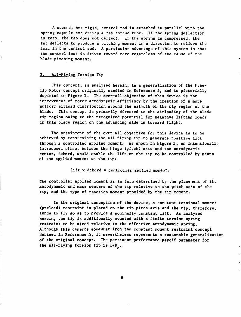
A second, but r i g i d , con t ro l rod i s a t tached i n p a r a l l e l w i t h t he spr ing capsule and d r i v e s a tab torque tube. I f the spr ing d e f l e c t i o n I s zero, the t ab does no t d e f l e c t . I f the sp r ing i s compressed, t h e t ab d e f l e c t s t o produce a p i tch ing moment i n a d i r e c t i o n t o r e l i e v e the load i n the con t ro l rod. A p a r t i c u l a r advantage of t h i s system i s t h a t the con t ro l load is driven toward zero regard less of the cause of the blade p i t ch ing moment.
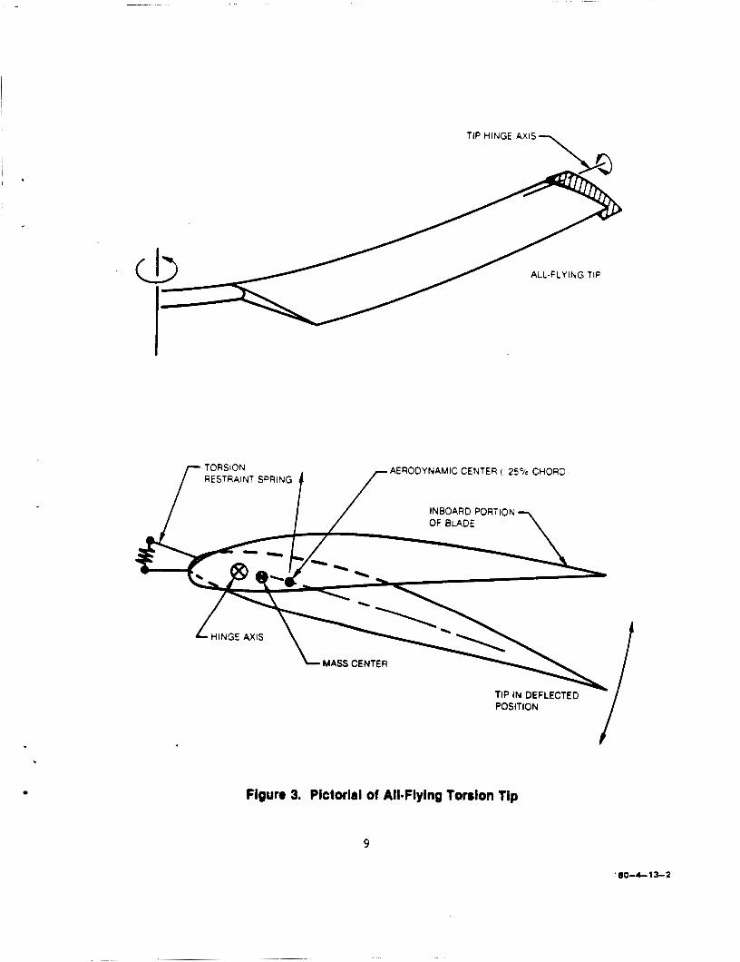
3. All-Flying Torsion Tip
This concept, a s analyzed here in , I s a gene ra l i za t ion of the Free- Tip Rotor concept o r i g i n a l l y s tud ied i n Reference 5 , and i s p i c t o r i a l l y depicted i n Figure 3 . improvement of r o t o r aerodynamic e f f i c i e n c y by the c r e a t i o n of a more uniform a i r l o a d d i s t r i b u t i o n around the azimuth of the t i p region of t h e blade. This concept i s pr imar i ly d i r ec t ed t o t h e a i r load ing of t he blade t i p region owing t o the recognized p o t e n t i a l f o r nega t ive l i f t i n g loads i n t h i s blade reg ion on the advancing s i d e i n forward f l i g h t ,
The over -a l l ob jec t ive of t h i s device i s the
The at ta inment of the over -a l l ob jec t ive f o r t h i s device i s t o be achieved by cons t ra in ing the a l l - f l y i n g t i p t o genera te p o s i t i v e l i f t through a con t ro l l ed appl ied moment. introduced o f f s e t between the hinge (p i t ch ) a x i s and the aerodynamic cen te r , Achord, would enable the l i f t on t h e t i p t o be con t ro l l ed by means of t he appl ied moment t o the t i p :
A s shown i n Figure 3 , an i n t e n t i o n a l l y
l i f t x Achord = c o n t r o l l e r appl ied moment.
The c o n t r o l l e r appl ied moment i s i n tu rn determined by t h e placement of the aerodynamic and mass c e n t e r s of t he t i p r e l a t i v e t o t h e p i t c h a x i s of t he t i p , and t h e type of r e a c t i o n moment provided by the t i p moment.
I n the o r i g i n a l conception of t h e device, a cons tan t t o r s i o n a l moment (preload) r e s t r a i n t is placed on t h e t i p p i t c h a x i s and t h e t i p , t h e r e f o r e , t ends t o f l y so as t o provide a nominally cons tan t l i f t . here in , t h e t i p i s a d d i t i o n a l l y mounted w i t h a f i n i t e t o r s i o n s p r i n g restraint t o be s i z e d relative t o t h e e f f e c t i v e aerodynamic sp r ing . Although t h i s depa r t s somewhat from t h e cons tan t moment r e s t r a i n t concept def ined i n Reference 5 , it neve r the l e s s r ep resen t s a reasonable gene ra l i za t ion of t h e o r i g i n a l concept. t he a l l - f l y i n g t o r s i o n t i p is L/De.
As analyzed
The p e r t i n e n t performance payoff parameter f o r
. 8
AERODYNAMIC CENTER 1 25% CHORD! RESTRAINT SPRING
INBOARD PORTION OF BLADE
TIP IN DEFLECTED POSITION
Figure 3. Pictorial of All*Flying Torsion Tip
9
’ 80-4- 13-2
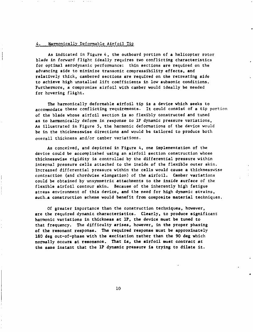
4 . Harmonically Deformable Airfoil Tip
As indicated in Figure 4 , the outboard portion of a helicopter rotor blade in forward flight ideally requires two conflicting characteristics for optimal aerodynamic performance: thin sections are required on the advancing side to minimize transonic compressibility effects, and relatively thick, cambered sections are required on the retreating side to achieve high unstalled lift coefficients in low subsonic conditions. Furthermore, a compromise airfoil with camber would ideally be needed for hovering flight.
The harmonically deformable airfoil tip is a device which seeks to accommodate these conflicting requirements. of the blade whose airfoil section is so flexibly constructed and tuned as to harmonically deform in response to 1P dynamic pressure variations, As illustrated in Figure 5, the harmonic deformations of the device would be in the thicknesswise directions and would be tailored to produce both overall thickness and/or camber variations.
It could consist of a tip portion
As conceived, and depicted in Figure 4 , one implementation of the device could be accomplished using an airfoil section construction whose thicknesswise rigidity is controlled by the differential pressure within internal pressure cells attached to the inside of the flexible outer skin. Increased differential pressure within the cells would cause a thicknessvise contraction (and chordwise elongation) of the airfoil, Camber variations could be obtained by unsymmetric attachments to the inside surface of the flexible airfoil contour skin. Because of the inherently high fatigue stress environment of this device, and the need for high dynamic strains, such.a construction scheme would benefit from composite material techniques.
Of greater importance than the construction techniques, however, are the required dynamic characteristics. Clearly, to produce significant harmonic variations in thickness at lP, the device must be tuned to that frequency. The difficulty arises, however, in the proper phasing of the resonant response. The required response must be approximately 180 deg out-of-phase with the excitation rather than the 90 deg which normally occurs at resonance. That is, the airfoil must contract at the same instant that the 1P dynamic pressure is trying to dilate it.
10

FREESTREAM VELOCITY
REGION OF TRANSONIC FLOW.
.*.THIN AIRFOILS ~= 180" LOW INCIDENCE ANGLES
NEEDED. LITTLE
REGION OF LOW SUBSONIC FLOW. HIGH INCIDENCE ANGLES (HIGH Cp S) 2. THICK. CAMBERED SECTIONS NEEDED
r L = O
Figure 4. Pictorial of Helicopter Rotor Disk in Fonnard Flight Showing Conflicting Requiromonts for Blade Tip Soctions .
11
80-4- 13-4

TIP SECTION AT k!'= 90 ' FLEXIBLE OUTER SKlhi
(TYP ) ATTACHMENT POINT
INTERNAL CELLS PRESSURiZED
TIP SECTION AT IL= 270'
1 I LOCAL DYNAMIC PRESSURE ACTS AS A 1 SUCTION TO DILATE AIRFOIL
INTERNAL CELLS DEPRESSURIZED Y
Figure 5. Pictorial of Harmonically Deformable Airfoil l i p 12

I t i s expected that appropriate gadgetry involving interblade coupling i s required t o achieve passive operation. operation are discussed i n the appropriate r e s u l t s subsection. A s with the a l l - f l y i n g tors ion t i p , the pertinent performance payoff parameter f o r t h i s device i s the l i f t t o (equivalent) drag r a t i o , LID,,
S p e c i f i c means for achieving t h i s
. 13

Analysis Requirements
Requirements for Present Study
As the descriptions of the selected appended aeroelastic devices offered in the above sub section demonstrate, these devices share iden- tifiable characteristics which pertain intrinsically to the requirements for their successful analysis:
1. The devices each generally comprise a simple dynamic element (spring-mass-damper) with a single degree-of-freedom descriptor which couples with the aeroelastics of an otherwise conventional state-of-the- art rotor blade.
2. The direct dynamic influence of the aeroelastic devices on the hub harmonic loads is subordinate to their indirect influence via modifi- cations to blade responses and resulting blade generated hub loads. whereas a fully-coupled, rotor-fuselage aeroelastic analysis would provide maximum rigor to the analysis, a more simple, conventional hub-fixed approach should yield adequate insights into the relative efficiencies of the devices.
Hence,
3. Over some spanwise portions(s) of the blade, the incremental aerodynamic loading description must account for the motion of the aeroelastic device. Typically, this incremental loading modifies the basic aerodynamic excitations of the blade (incremental section coefficients) as well as generating airload excitations of the device itself, Furthermore, because the devices would generally be expected to produce abrupt deviations from the otherwise smooth blade geometries, abrupt and concentrated airloadings at these deviations would ensue.
4. The aerodynamic environment in which these devices (as well as the basic blade itself) operate is essentially unsteady. motions and potentially high reduced frequency transient phenomena impact on the operation of the three torsionally active devices and, hence, on their potential merit. and phase lags in both the stalled and unstalled aerodynamic loadings.
Multi-harmonic blade
This impact requires an attention to the attenuations
5 . The operation of any blade appended device with respect to any one specific performance index cannot be isolated from the inherent aeroelastic stability of the device. Thus, the aeroelastic analysis must be sufficiently comprehensive as to be able to demonstrate any inherent lastability condition caused by a selection of parameters which might otherwise demonstrate superior performance in specific selected payoff parameter.
,
14

G4OOPA Rotor Aeroelastic Analysis
The analysis selected as the tool for analyzing the four appended devices is the "PA" version of the United Technologies Corporation G400 Rotor Aeroelastic Analysis. As first reported in Reference 6, this basic analysis has evolved into a family of multi-purpose programs directed to the analysis of all major rotor types and complexities with application to helicopters, wind turbines and propellers.
Generally the G400 analyses are formulated on a beam bending-torsion basis and include a rigorous modeling of large, nonlinear and time-varying structural twist. The differential equations of blade bending (flatwise and edgewise) and torsion incorporate the salient features of Reference 7 and are solved using a Galerkin procedure wherein normal "uncoupled" vibration mode shapes and their spanwise derivatives along with the spanwise derivative of the blade (nonlinear) twist are combined to approximate "coupled" blade deflections. includes the use of predetermined static airfoil data, constant or variable (multiply harmonic and spanwise variable) inflow and unsteady airload effects (both unstalled and stalled), An important capability of the G400 analysis to the present study is the implementation of a rigorous method f o r including detailed inertial and aerodynamic loadings and internal structural (elastic) characteristics with unlimited attention to nonlinearities. An important contribution to this implementation and to the ability to calculate dynamic loads arising from concentrated load sources such as pendulum absorbers and the herein considered appended devices is the force-integration method for calculating blade stresses and hub loads (Reference 8).
The aerodynamic description
The "PA" version of G400, as reported in Reference 9, was selected for the present study because it provided the best basis for meeting the above itemized requirements. In particular, by virtue of the explicit modeling of pendulum absorbers, this version already incorporated the structuring required to accommodate the differential equations for a single degree-of-freedom dynamic system attached to the rotor blade. Beyond this existing capability, however, explicit modifications were required and are described in a subsequent section.
15

LIST OF SYMBOLS
[AI Spanwise aerodynamic diffusion matrix for six outermost blade segments. ND.
a a , a Components of inertial acceleration in the "5" coordinate x5D '5 2 5 system. m/s 2 ,
b Number of blades
C Theodorsen function
CL/c, C I C Rotor aerodynaxic lift and propulsive force coefficients over solidity, respectively.
PF
cT Damper rate of explicit restraint of torsionally active device, Nms/rad.
C Blade section chord, n.
T C
'e
e
Chord of appended device, rc
Rotor equivalent drag (see Eq. 19), N.
x2 coordinate of coincident flat-lag hinge or hingeless blade off set point m.
f Equivalent flat plate area for defining aerodynamic drag, K.
Coupling gain for tab motion per root deflection, ED. GT
If Rotor horsepower.
Spring rate of explicit restraint of torsionally active device, (alternate forms), Nm/rad.
KTD K6T
R Ke Blade root torsion spring to account for control system flexibility, Nm/rad
Gain constants used for passive dynamic implementation of the hannonic dilational airfoil tip. K1' K2
k r k Mass radii of gyration of tab (or tip) mass center inertia 'T 'T about axes parallel and normal to tab chordline, respectively, IC.
c
17

LIST OF SYMBOLS cont inued
z k P k y l o 10
L
1, M
M aPPT
res i d M
MT
X M
6T
m 0
- m
n
P
PF
Uass r a d i i of gy ra t ion of blade s e c t i o n about axes through and perpendicular t o the spanwise (x5) a x i s and i n the chordvise and thicknesswise d i r e c t i o n s , r e spec t ive ly , m.
Rotor l i f t , N.
Distance from t a b device hinge a f t t o t a b mass c e n t e r , m.
Mach number
Constant appl ied moment about hinge f o r t o r s i o n a l l y a c t i v e device, Xr.
Residual e l a s t i c moment about hinge r e s i s t i n g aerodynariic and i n e r t i a l oads , Nm.
Uass of the t o r s i o n a l l y a c t i v e device, kg.
Moment about hinge a x i s of t he t o r s i o n a l l y a c t i v e device.
Reference blade mass d i s t r i b u t i o n , taken t o be t h a t of t he 5 t h blade segment, kglm.
Blade mass d i s t r i b u t i o n , (ND)
Blade segment index
Per r o t o r r evo lu t ion
Rotor propuls ive f o r c e , h’.
Sect ion shear load d i s t r i b u t i o n 6 In d i r e c t i o n s of axes i n t h e 5- coord ina te system, (ND)
S t a t i c a i r f o i l p re s su res de f in ing t h e ope ra t ion of the harmonic d i l a t l o n a l a i r f o i l t i p , Pa.
18

LIST OF SYMBOLS cont inued
Q Quas i - s t a t i c a i r f o i l downwash v e l o c i t y func t ion f o r a i r f o i l s wi th t abs , m/s.
Effec t ive a i r f o i l dcrwnwash v e l o c i t y func t ion f o r a i r f o i l s w i th t abs , m/s.
QE
A i r f o i l downwash v e l o c i t y func t ion f o r a i r f o i l s wi th t a b s , cor rec ted using unsteady decay parameter a lgori thm, m/s.
Blade j ' t h t o r s ion modal response va r i ab le . 1
9,
R Rotor r ad ius , m.
Spanxise ex ten t of appended device, m. LRT
- r
- ef f r
5 Blade spanwise coordinate , measured from o f f s e t , e, i n x d i r e c t i o n , (h?))
Effec t ive (a rea cen te r ) r ad ius of the planform of the harmonic d i l a t i o n a l t i p , ND with r e spec t t o R.
C r , Cx n ' t h blade spanwise segment ( a rc ) length , (KD) n n
F r i c t i o n (Coulomb) damping moment about hinge f o r t o r s i o n a l l y a c t i v e device, Nm.
Components of Blade Root Shears i n (nonrotat in&) long i tud ina l , 2
s , s 9 s
'1 1 l a t e ra l and v e r t i c a l d i r e c t i o n s , r e spec t ive ly , N.
6 Aerodynamic time
Trimmed r o t o r f l i g h t rpeed, m/s 8nd (kts) "T
19

LIST OF SYMBOLS c m t hued
Vector of components of incremental displacement of a point In the "5" coordinate system, m.
X cen Nondimensional blade spanwise station measured from center of rotation.
Components of the 5-coordinate system, defined to be rotating with the hub, but at the blade coned and lagged position, (hT)
Y "CG
Chordwise distance of blade section mass center forvard from the elastic axis, (ND).
'i Perturbational thickness ratio response for the i'th blade.
Section angle-of-attack, deg and rad D
Effective aerodynamic section angle-of-attack, Including effects of unsteady decay parameter, deg.
a Q Quasi-static angle-of-attack, rad.
a k' Aerodynamic section unsteady decay parameter, rad.
Prantl-Glauert transformation factor, ( = -1 E
Torsion deflection of torsionally active device, positive TE up, rad. @T
0 ET
8T1
Steady component of torsion related device deflection, rad.
Component of tab torsion motion due to ganging with root torsion motion, rad.
Deflection mode shape for the j'th torsion normal mode, (hi)
20

LIST OF SYMBOLS cont inued
0 Total local blade pitch angle, radians.
IJ
0
Rotor advance ratio, (= flight speed/RR)
Rotor solidity ( = bc/rR).
TIC Airfoil thickness ratio.
(T/c)~ , (TIC) First hannonic cosine and sine components of perturbational C Is thickness ratio.
Generalized Wagner function, with compressibility corrections. eC
$ Blade azimuthal (angular) position, rad and (deg)
R Rotor rotational frequency, or speed (rpm)
- - - '*I ~ u V s u E (Nondimensional) uncoupled natural frequencies of i'th f 1acr;ise
bending mode, k'th edgewise bending mode and j'th torsion modi, '
2 1

Subscripts
a 0
( )T
Superscript s
Arising from aerodynamic loading
Relating to the appended device (tip or tab)
Pertaining to dynamic inertia loads
Pertaining to elastic restraints
Differentiation with respect to (r/R)
Perturbational quantity
Kondimensionalization by combinations of m , R and/or C
Differentiation with respect to (at)
0
22
MATHEMATICAL DEVELOPMEKT
For purposes of t h i s s tudy, the required modif icat ions of the G4OOPA a n a l y s i s f a l l i n t o two main ca t egor i e s : those needed f o r t h e t h r e e t o r s i o n a l l y a c t i v e devices (tuned tab , c o n t r o l coupled t a b , and the a l l - f l y i n g t i p ) , and those f o r t h e d i l a t i o n a l s e c t i o n t i p . of t h i s s e c t i o n desc r ibes the a d d i t i o n a l formulations r equ i r ed t o convert t he e x i s t i n g G400PA formulations f o r a purely mechanical conventional blade appended, pendular absorber t o those f o r an aerodynamically a c t i v e pendular mass whose hinge i s now o r i en ted p a r a l l e l t o t he blade p i t c h axis. These formulat ions a r e more o r l e s s common t o a l l t h r e e t o r s i o n a l l y a c t i v e devices . Where noted, some a r e appropr i a t e ly p e r t i n e n t t o only one o r two of these devices. The l a s t p a r t of t h i s s e c t i o n d e a l s w i th design cons ide ra t ions r e l e v a n t r e l evan t t o the d i l a t i o n a l s e c t i o n t i p and wi th those GOOOPA modif icat ions necessary f o r i t s a n a l y s i s w i th in t h e scope of t he present study.
The f irst p a r t
Torsional ly Active Devices
Four b a s i c formulations and subsequent modif icat ions of t h e G400PA were required :
Development of the i n e r t i a loadings f o r a pendular mass with an a x i a l l y mounted hinge.
Inc lus ion of e l a s t i c and/or coupling c o n s t r a i n t s of the device about t h e hinge.
Extension of c l a s s i c (frequency domain) unsteady a i r l o a d s formulat ions t o a t ime-history s o l u t i o n format.
Development of a method for accounting f o r spanwise aerodynamic cross- t a l k e f f e c t s . boundaries of t h e devices .
These arise from t h e abrupt loadings changes a t the
Supplementary Assumptions
To achieve a s u c c e s s f u l modeling of the t o r s i o n a l l y active devices the following l ist of assumptions were made ( i n a d d i t i o n t o those s t a t e d i n Reference 9) :
23

1. as defined by the spanwise c e n t e r s of two s e l e c t e d blade segments, a s t y p i c a l l y used f o r blade segmentation. p o i n t s is nominally p a r a l l e l t o t he blade (reference) p i t c h a x i s .
The device is a r i g i d body at tached t o the blade proper a t two p o i n t s
The hinge l i n e defined by these two
2 . The t o r s i o n a l device i s uniform i n p r o p e r t i e s i n the spanwise d i r e c t i o n .
3. For purposes of de f in ing the incremental i n e r t i a loads on the blade proper due t o device motion, t he device is approximated by two incremental mass d i s t r i b u t i o n s a t each of t he two attachment segments, each def ined by ha l f t he device mass.
4. combination of sp r ing , damper, f r i c t i o n , constant valued and c o n t r o l coupled moments (see Figure 6 ) .
The device is mechanically r e s t r a i n e d t o t h e blade by a p a r a l l e l
5 . The normal (uncoupled) mode inpu t p repa ra t ion c a l c u l a t i o n s f o r t he blade proper are t o be performed with a blade mass d i s t r i b u t i o n appropr i a t e t o the blade ( a s designed t o inc lude t h e device) but with the a c t u a l moveable device mass removed. This moveable device m a s s must then be e x p l i c i t e l y added i n the G400PA equat ion d e s c r i p t i o n .
6. The aerodynamic d e s c r i p t i o n s f o r both t h e device and blade proper should include unsteady e f f e c t s . Because s t a l l f l u t t e r r e p r e s e n t s a "higher-order" dynamic phenomenon beyond the scope of t h e p re sen t s tudy, t he appropr i a t e unsteady e f f e c t s are those two-dimensional formulat ions based on u n s t a l l e d p o t e n t i a l flow. The c l a s s i c theory of Theodorsen and Garr ick (Reference 10) i s an appropr i a t e b a s i s .
7. a i r l o a d s accruing only from the incremental l i f t l oads due t o device d e f l e c t i o n . These c r o s s t a l k e f f e c t s are approximated by a cons t an t (cross- t a l k ) matrix premult iplying t h e (two-dimensional) s t r i p theory incremental spanwise a i r l o a d d i s t r i b u t i o n .
Aerodynamic spanwise c r o s s t a l k e f f e c t s are l i m i t e d t o those c i r c u l a t o r y
Iner t ia Load D i s t r i b u t i o n s f o r Pendular Mass
The d e r i v a t i o n of t h e dynamic loads a c t i n g on t h e t o r s i o n a l l y a c t i v e device fol lows from a s t r a igh t fo rward a p p l i c a t i o n of appropr i a t e coordinate t ransformations and d i f f e r e n t i a t i o n s of a p o s i t i o n vec to r . Using Equation (35) of Reference 6 as a s t a r t i n g p o i n t and r e f e r r i n g t o F igu re 6 , one can wri te the
24

c
25
83-6-1034
i
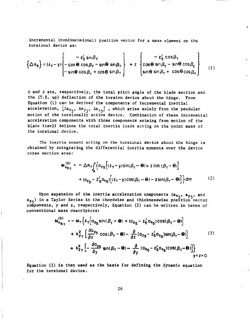
incremental (nondimensional) p o s i t i o n vector f o r a mass element on the t o r s i o n a l device as:
- 2: cos& cos@ sinp, - sin0 cosp, I sin@ sinp, + ~ ~ s @ c o s p ,
sinPT
- sin@ COS^, + cos@ sin&
- {ax,} U T - Y ) - cos@ cosp, - sin@ sin@,
0 and f! a r e , r e s p e c t i v e l y , t he t o t a l p i t c h angle of t he blade s e c t i o n and t h e (T.E. up) d e f l e c t i o n of t he t o r s i o n device about the hinge. Equation (1) can be derived the components of incremental i n e r t i a l a c c e l e r a t i o n , 1AaX5, Aayj, Aaz5j , which arise s o l e l y from the pendular motion of t he t o r s i o n a l l y a c t i v e device. Combination of t hese incremental a c c e l e r a t i o n components w i th those components a r i s i n g from motion of the blade i t s e l f de f ines t h e t o t a l i n e r t i a loads a c t i n g on t h e point mass of t h e t o r s i o n a l device.
From
The inertia moment acting on t he torsional device about the hinge is obtained by i n t e g r a t i n g the d i f f e r e n t i a l i n e r t i a moments over t h e device c o r s s s e c t i o n a rea :
Upon expansion of t h e iner t ia a c c e l e r a t i o n components (a, , aygB and az5) i n a Taylor S e r i e s i n t h e chordwise and thicknesswise p o s l t i o n v e c t o r components, y and 2 , r e s p e c t i v e l y , Equation (2) can be w r i t t e n i n t enns of conventional mass d e s c r i p t o r s :
I
Equation (3) i s then used as t h e b a s i s for def in ing t h e dynamic equat ion f o r t h e t o r s i o n a l device.
26
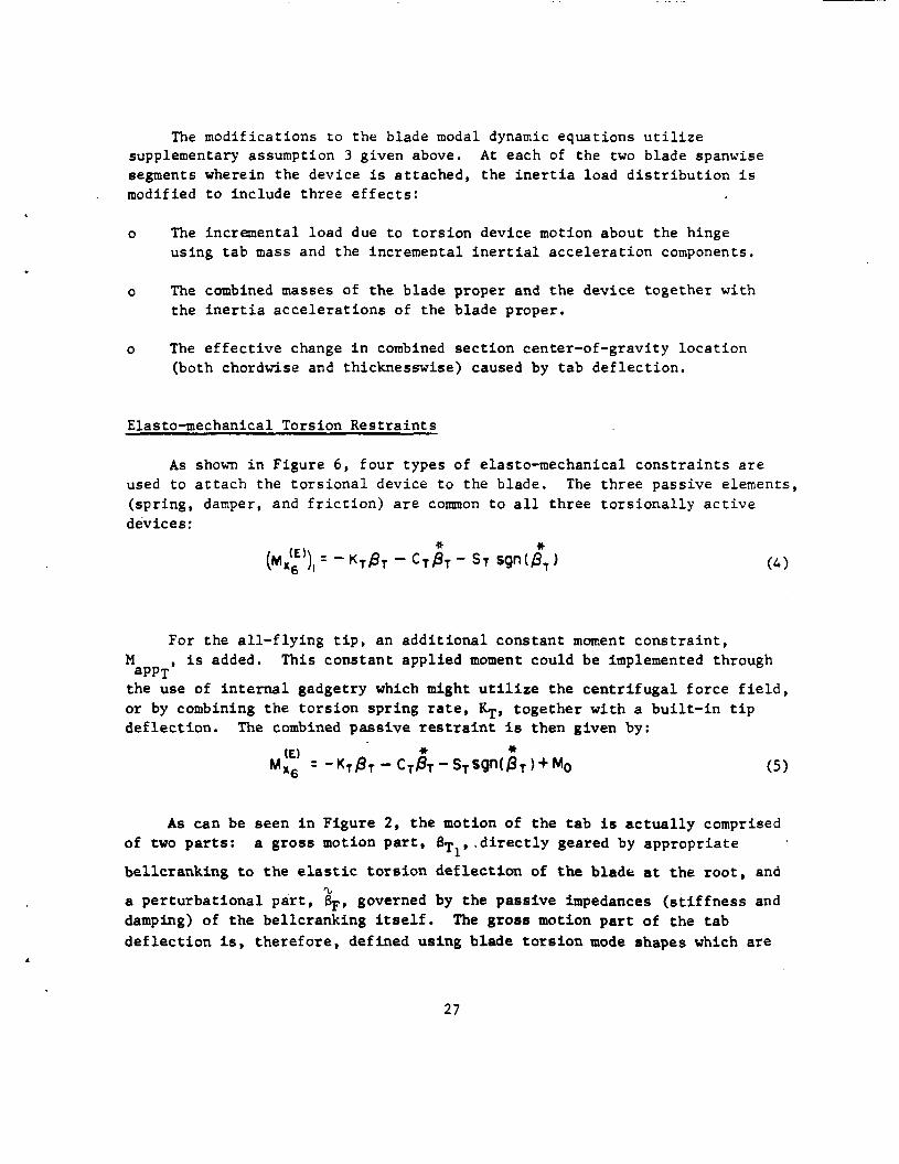
The modif icat ions t o the blade modal dynamic equat ions u t i l i z e supplementary assumption 3 given above. A t each of the two blade spanwise segments wherein t h e device is a t t ached , the i n e r t i a load d i s t r i b u t i o n i s modified t o include t h r e e e f f e c t s :
o The incremental load due t o t o r s i o n device motion about t h e hinge using t a b mass and the incremental i n e r t i a l a c c e l e r a t i o n components,
o The combined masses of t he blade proper and t h e device toge the r with the i n e r t i a a c c e l e r a t i o n s of t he blade proper.
o The e f f e c t i v e change i n combined s e c t i o n center-of-gravity l o c a t i o n (both chordwise and thicknesswise) caused by t a b d e f l e c t i o n .
Elasto-mechanical Torsion R e s t r a i n t s
As shown i n Figure 6, fou r types of elasto-mechanical c o n s t r a i n t s a r e used t o a t t a c h the t o r s i o n a l device t o the blade. The t h r e e passive elements, (spr ing, damper, and f r i c t i o n ) a r e common t o a l l t h r e e t o r s i o n a l l y a c t i v e devices:
For the a l l - f l y i n g t i p , an a d d i t i o n a l constant moment c o n s t r a i n t , M , i s added. This cons t an t appl ied moment could be implemented through
t h e use of i n t e r n a l gadgetry which might u t i l i z e t h e c e n t r i f u g a l f o r c e f i e l d , o r by combining the t o r s i o n sp r ing rate, $, t oge the r w i th a b u i l t - i n t i p d e f l e c t i o n . The combined pass ive restraint is then given by:
aPPT
As can be seen i n Figure 2, t h e motion of t h e t a b is a c t u a l l y comprised of two p a r t s :
be l l c r ank ing to t h e elastic t o r s i o n d e f l e c t i o n of t h e blade a t t h e r o o t , and
a p e r t u r b a t i o n a l p a r t , 8F, governed by the pas s ive impedances ( s t i f f n e s s and damping) of t he bel lcranking i t s e l f . d e f l e c t i o n is, t h e r e f o r e , def ined us ing blade t o r s i o n mode shapes which are
a gross motion p a r t , B T ~ , . d i r e c t l y geared by appropr i a t e
%
The g ross motion p a r t of t he t a b
27
ca lcu la t ed using r o o t t o r s i o n sp r ings . Such mode shapes have nonzero roo t (O), which can be geared ghrough a gain parameter, GT, t o de f ine
Thus, t he t o t a l c o n t r o l coupled t a b motion is defined by: j
the gross motion.
4- P,, + 4 where
Time Domain Unsteady Air loads
Each of t h e t h r e e t o r s i o n a l l y a c t i v e devices e n t a i l s a s i g n i f i c a n t degree of coupling between the blade f l a t w i s e bending modes and the t o r s i o n a l response of t h e device i t s e l f . Consequently, t he p o t e n t i a l e x i s t s f o r a e r o e l a s t i c i n s t a b i l i t y with these devices . Such i n s t a b i l i t i e s , moreover, could occur a t response f r equenc ie s s u f f i c i e n t l y high t o warrant t h e i n c l u s i o n s of the l a g s and a t t e n u a t i o n s due t o unsteady aerodynamic e f f e c t s . t r u e f o r t h e pas s ive tuned t a b which is t o o p e r a t e a t blade passage frequencies . The presence of a t r a i l i n g edge t a b w i t h two of t he t o r s i o n devices , a s a d i s t i n c t aerodynamic element, f u r t h e r d e f i n e s an aerodynamic modeling over and above t h e usua l q u a s i - s t a t i c s t r i p theory t y p i c a l l y used for t h e nonappended blade. tab f e a t u r e s is r equ i r ed i n a time-domain format. c a l c u l a t i o n s are performed by (time) i n t e g r a t i n g t h e non l inea r dynamic equat ions and t h e aerodynamics must t h e r e f o r e be def ined by appropr i a t e d i f f e r e n t i a l equat ions.
This is e s p e c i a l l y
F i n a l l y , t he i n c l u s i o n of these unsteady a i r l o a d i n g and t r a i l i n g edge A l l t he G400PA response
U n s t e a 3 Decg Parameter --- -- ----- The approach followed h e r e i n draws upon t h e use of t h e unsteady decay
I parameter, ow, descr ibed i n d e t a i l in R e f . 11 and def ined as fol lows:
I 28

This parameter is an equivalent embodiment of t he Wagner func t ion (and i t s Four ie r t ransform counterpar t , t he Theodorsen func t ion - see Ref. 12 ) . This aw parameter when taken toge ther w i th t h e q u a s i - s t a t i c angle-of-attack de f ines an equiva len t angle-of-attack:
Q ~ = Q ~ - Q ,
which when used q u a s i - s t a t i c a l l y produces a i r l o a d s which c l o s e l y approximate t h e unsteady loadings r e s u l t i n g from i n d i c i a 1 responses (Wagner problem) as w e l l a s s inuso ida l ones (Theodorsen problem).
T r a i l i n g Edge Tab E f f e c t s - - - - - - - - - - - - - I n t h e Ref. 10 formulat ion f o r t he unsteady aerodynamic loading f o r a
two-dimensional a i r f o i l wi th t ab , t he e f f e c t s of c i r c u l a t o r y unsteady e f f e c t s are seen t o be contained i n the s i n g l e product CQ. t h e f a m i l i a r Theodorsen func t ion , C , and a func t ion Q which i s analogous t o a product of t h e q u a s i - s t a t i c angle-of-attack (without t ab ) , aQ, and t h e f rees t ream v e l o c i t y , V . he re in f o r combining t h e unsteady decay parameter approach descr ibed above wi th t h e formulat ions of Theodorsen and Garr ick (Ref. 10).
This product c o n s i s t s of
This analogy sugges ts t h e h e u r i s t i c approach s e l e c t e d
S p e c i f i c a l l y , but f o r t h e CQ terms i n t h e equat ions f o r l i f t , moment and t a b moment given by Theodorsen and Garr ick, a l l o t h e r terms are a l ready def ined i n t h e t i m e domain. The CQ term is redef ined i n t o t h e time domain by means of a n equiva len t Q:
Q , = Q - Q ,
where
Jus t as aE is used q u a s i - s t a t i c a l l y t o inc lude unsteady e f f e c t s , so too is t h e QE parameter used as a s u b s t i t u t i o n f o r t h e CQ frequency-domain def ined product .
29

Spanwise Cross ta lk Ef fec t s
As demonstrated by References 13 and 1 4 , t he s o l e use of s t r i p theory
I n such in s t ances t h e incremental loadings pred ic ted over the cannot adequately desc r ibe t h e a i r load ing i n the v i c i n i t y of e i t h e r boundary of t h e tab . span of t h e t ab are r e a l i s t i c a l l y d i f fused over t he ad jacent po r t ions of the blade (or wing). This has the r e s u l t t h a t t h e a c t u a l e f f e c t i v i t y of the t a b is somewhat reduced from what would be ca l cu la t ed us ing s t r i p theory .
The r igorous accounting of t he three-dimensional c h a r a c t e r i s t i c s of a de f l ec t ed t a b on a h e l i c o p t e r r o t o r blade i n forward f l i g h t does not ye t e x i s t and some form of " f i r s t order" approximation is requi red . used here in is based on a "spanwise d i f fus ion" mat r ix , which when post- mu l t ip l i ed by the two-dimensional loading d i s t r i b u t i o n vec to r g ives an approximation t o the three-dimensional loading. assumption 7 given above, t h i s spanwise d i f f u s i o n matr ix , A, is appl ied only t o the incremental loading caused by device de f l ec t ion :
The approach
As per supplementary
The a c t u a l spanwise d i f f u s i o n mat r ix used f o r the c a l c u l a t i o n s t o be discussed i n the next s e c t i o n was ca l cu la t ed using NASA suppl ied tes t d a t a f o r a Blackhawk h e l i c o p t e r r o t o r blade f o r t he s i x (6) outboard segments s e l ec t ed :
.510 .094 .500 .187
.050 .146
.050 .0563 ,120 .150
where
{ ApZr 1 = Incremental a i r l o
.0285 .0239
.160 .080
.493 .148 ,180 .370 . l o 7 . .170 ,205 .395
.0096
.028 ,056 ,080 .243 .600
d d i s t r i b u t i o n due
.002
,100
( t ab ) d e f l e c t i o n ~~ 3 f l a p -'a f o r segments 10 through 15.
segmentation is as fol lows: Note t h a t t h e selected spanwise
= [0.05, 095, .05 , - 0 5 , .04, .01 J 10-15
30

Harmonically Dilational Airfoil Tip
In contrast to the three torsionally active devices the operation of the harmonically dilational airfoil tip does not involve potential encounters with any known unstable aeroelastic phenomena. Thus, any aeroelastic or rather aeromechanical instabilities of this device would be governed by the type of excitation scheme used and would not necessarily be inherent in the concept itself. Thus, the focusing of the analysis on the dynamics of any one type of excitation scheme would appear to be inappropriate to the intent of the present study (i.e., to assess the aerodynamic performance payoff of the device). practical excitation scheme was made in the GOOOPA program. Instead, the response of the dilational tip was modeled directly wherein the amplitude and phases were input for parametric variation, For completeness, however, a potential scheme for excitation was conceived as part of this study. In the subsections to follow the actual program modifications incorporated are first discussed. Then, the potential scheme for passive excitation is described.
For this reason no incorporation of the dynamics of a potentially
Variable Airfoil Thickness Ratio
The original GOOOPA storage and utilization of static airfoil data consisted of multi-variable tables of CQ, Cd, and aerodynamic coefficients.
Interpolation table look-up was based on selected radial station (airfoil type variation), Mach number, and angle-of-attack. For analysis of the harmonically dilational airfoil tip, the table look-up organization and interpolation with regard to radial station variation, rn, was replaced by thickness ratio variation, T / C :
C q ( M 9 Q 9 rn ) -.I Cq ( M 3 Q 9 r /C )
where q refers to either aerodynamic type ( a , d , mc/4). Further, the total thickness ratio was assumed to consist of a steady value, (T/C)~ which is dependent on span, and a perturbational part which varies dynamically in accordance with the operation of the device. ratio to be limited by minimum and maximum values, the total thickness ratio is expressible as:
Assuming the total thickness
31

where
The implementation of Eq. (14b) r e q u i r e s t he d e f i n i t i o n and inpu t of a spanwise d i s t r i b u t i o n a r r a y , ( T / c ) ~ ~ , f o r t h e d e s c r i p t i o n of t he base l ine
r o t o r blade, and a d e f i n i t i o n of a harmonic r ep resen ta t ion f o r the p e r t u r b a t i o n p a r t :
The c o e f f i c i e n t s , A ( T / c ) l C and A(T/C)lS, a r e thus the c y c l i c components of
harmonic a i r f o i l d i l a t i o n . Together w i t h t he spanwise e x t e n t of t he d i l a t i o n a l t i p , t hese c y c l i c components f o r n the p r i n c i p a l parameters t o be va r i ed i n t h i s study.
Prel iminary Conception f o r Implementation
As schematical ly depicted i n Fig. 7 , a prel iminary concept f o r implemen- t a t i o n of t h e device would use an a i r f o i l c o n s t r u c t i o n whose thicknesswise r i g i d i t y i s c o n t r o l l e d by t h r e e pressures:
i s t h e s t a t i c p res su re o u t s i d e t h e f l e x i b l e o u t e r s k i n and is chordwise l o c a t i o n dependent. as p2 and t h a t i n s i d e t h e a i r f o i l , but o u t s i d e t h e i n t e r n a l p re s su re cel ls is
denoted as p3. cells (Ap = pz-p3) would cause a thicknesswise c o n t r a c t i o n (and chordwise
elongat ion) of t h e a i r f o i l .
p1, p2, and p3. The p res su re p1
The p res su re i n s i d e t h e i n t e r n a l p r e s s u r e cel ls is denoted
Increased d i f f e r e n t i a l p re s su res w i t h i n and o u t s i d e the p re s su re
32

l h iTE9104 OF TYPICAL INTERNAL CELL P EXTERIOFi OF INTERNAL CELL P3 27 A-
EXTERIOR OF SKIN. P1
\ / ', ' '. #'
(ADVANCING SIDE,
<-&+- SECTION A-A
A / ARE CONNECTED TO
INNER PORTIONS OF BLADE ARE RIGID
RAM (TOTAL) PRESSURE ORIFICE (TYP)
PRAM = P, + 1QP UT
WHERE
2
UT, = I!R [ r + Fsn (4 + 1x12) 1
HAS 1P AND 2P COMPONENTS "TI
INTERNAL CELL AIR VOLUMES OF RESPECTIVE FOLLOWING B L ~ D E S
EXTERIOR TO CELL AIR VOLUMES OF OPPOSING BLADE TIPS ARE COYkEZTEC
1=4 I (RE1
r ' 0
'REATING SIDE)
Figure 7. Schomatic of Excitation Scheme for Harmonically Doformabie Airfoil Tip 33
81 -1 2-0-1

Because of the inhe ren t ly high f a t i g u e s t r e s s environment of t h i s device and the need f o r high dynamic s t r a i n s , a cons t ruc t ion scheme u t i l i z i n g compo- s i t e materials might be employed, Furthermore, because the device must main- t a i n a reasonably smooth a i r f o i l contour wi th in the d i l a t i o n a l range, t he ou te r a i r f o i l sk in would have t o be s t r u c t u r a l l y r e in fo rced between the i n t e r n a l c e l l t o sk in attachment p o i n t s .
Of equal importance t o these cons t ruc t ion cons ide ra t ions , however, a r e t h e required s t a t i c and dynamic c h a r a c t e r i s t i c s . S t a t i c a l l y , the a i r f o i l mus t maintain i t s "compromise" thickness r a t i o , roughly halfway between the f u l l y d i l a t e d and contracted p o s i t i o n s (as defined i n hovering f l i g h t ) , i n a l l f l i g h t condi t ions. component of dynamic p res su re . Dynamically, t he a i r f o i l must o s c i l l a t e with s i g n i f i c a n t harmonic v a r i a t i o n s i n thickness a t a once p e r r ev (1P) frequency, and, hence, must be tuned t o r e sona te a t t h a t frequency. A requirement i n implementing such a device success fu l ly arises, however, i n t h e proper phasing of t he resonant response. The required response mus t be approximately 180 degrees out-of-phase wi th the e x c i t a t i o n from t h e o u t e r s t a t i c p re s su re , p l , r a t h e r than the 90 degrees which would normally occur from t h i s e x c i t a t i o n .
That i s , i t must no t become d i l a t e d due t o t h e bas i c s t e a d y
An implementation of t h i s device which p o t e n t i a l l y s a t i s f i e s t hese requirements i s based on a four-bladed r o t o r conf igu ra t ion as shown i n Fig. 7. This implementation c o n s i s t s of t he following elements: (1) t o t a l o r "ram" p res su re o r i f i c e s loca t ed on each blade a t o r near t he s t agna t ion po in t on the leading edge, as f a r outboard along the blade as i s p r a c t i c a l ; (2) connections of t hese ram pres su re o r i f i c e s t o the i n t e r n a l c e l l s of t h e i r r e s p e c t i v e following blades; and (3) i n t e rconnec t ions of t he p3 i n t e r n a l p re s su res between opposi te blades.
This Implementation s a t i s f i e s t h e phasing requirement i n t h a t t he c o n t r a c t i o n a l e x c i t a t i o n , 1P v a r i a t i o n i n P 2 - ~ 3 , is appl ied 90 deg i n phase ahead of when the c o n t r a c t i o n i s t o occur. f o r t he I n t e r n a l c e l l p re s su re , p2, acts t o s t a b i l i z e t h e a i r f o i l s t a t i c a l l y i n hover. t he func t ion of g iv ing t h e i n t e r n a l (p=p3) a i r , i n e f f e c t , a harmonic accumulator so t h a t t he a i r f o i l can undergo a 1P volume change wi th n e g l i g i b l e impedance, In e f f e c t t h i s implementation i n s u r e s t h a t t h e ApCpz-p3) p re s su re d i f f e r e n t i a l is propor t iona l t o t h e dynamic p r e s s u r e (=%pV2) a t t h e preceding b l ade ,
Furthermore, t h e use of r a - pressure
The interconnect ion of t he p3 p res su re of t h e opposing blades serves
A s impl i f i ed mathematical modeling of t h e p e r t u r b a t i o n a l t h i ckness r a t i o , ( Z = A ( - K / C ) ) assumes t h a t f o r t h e i t h blade, Zi is governed by a b a s i c a l l y second
34

order l i n e a r d i f f e r e n t i a l equat ion wi th e x c i t a t i o n sources from s t a t i c and blade advanced ram pressures :
where t h e e x c i t a t i o n components a r e given by:
Note t h a t t he dynamic e x c i t a t i o n of t he i t h blade given i n Eq. (17) uses the o r i f i c e ram pres su re from t h e ( i + l ) t h blade. Note a l s o that t h e s t a t i c pressure e x c i t a t i o n i s p ropor t iona l t o the t o t a l th ickness r a t i o , ( T / c ) . Thus, t he s e c t i o n d i l a t i o n a l p re s su re i s i t s e l f p ropor t iona l , i n p a r t , t o the per turba- t i o n a l d i l a t i o n , Z i .
The above mathematical modeling r ep resen t s a f i r s t c u t a t def in ing the physics of t h e device. The va r ious cons tan ts used i n E q s . (16) through (18) can p resen t ly only be roughly estimated. implemented i n the GOOOPA a n a l y s i s and, with appropr i a t e e s t ima t ions of t he cons tan ts , solved as p a r t of t he aeromechanics of t h e d i l a t i o n a l t i p . This approach, however, was deemed ou t s ide t h e p r i n c i p a l scope of t h i s study and was, t h e r e f o r e , deferred t o a more in t ens ive des ign s tudy and eva lua t ion of t h i s device.
These equat ions could have been
35
RESULTS
Basel ine Rotor Configurat ion
For the purpose of providing a numerical v e h i c l e f o r eva lua t ing the fou r a e r o e l a s t i c appended devices , t h e Blackhawk UH-60A r o t o r blade w a s se lec ted . This p a r t i c u l a r s e l e c t i o n was made based on t h e t imely a v a i l a b i l i t y of t h e da t a , and on t h e f a c t t h a t t h i s r o t o r r ep resen t s a r e l evan t , s ta te -of - the-ar t , convent ional ( a r t i c u l a t e d ) b lade design. The appropr i a t e basic b lade geometry and dynamic d a t a f o r t h i s blade are summarized i n Tables I and 11. Table I p resen t s t h e b a s i c g ross des ign parameters which s i z e and dynamically d e f i n e t h e b a s e l i n e r o t o r blade. A s t h i s t a b l e Implies , t h r e e f l a t w i s e (uncoupled) modes, one edgewise mode and one t o r s i o n mode, were used t o approximate t h e elasto-mechanics of the blade. Table I1 presen t s t he d e t a i l e d d i s t r i b u t i o n of p e r t i n e n t geometric and mechanical ( re ference) blade p r o p e r t i e s used i n the c a l c u l a t i o n s . I n subsequent c a l c u l a t i o n s f o r each of t h e devices under cons idera t ion , v a r i o u s of t hese e n t r i e s were appropr i a t e ly a l tered t o accommodate t h e phys ica l c o n s t r a i n t s requi red by t h a t device.
T r i m e d F l i g h t Conditions
Se lec t ion of Cases
Each of t he f o u r appended devices w a s conceived f o r a t t a i n i n g improvements i n some type of performance index, e i t h e r dynamic o r aerodynamic, gene ra l ly a t t h e high speed end of t he f l i g h t envelope. Accordingly, two b a s i c trimmed f l i g h t cond i t ions , which accentua te t h e high speed a spec t , were selected f o r eva lua t ing t h e p o t e n t i a l g a i n s achievable wi th t h e s e l e c t e d devices . Table 111 below summarizes t h e t r i m cond i t ions se l ec t ed f o r t h e UH-60A r o t o r . Note t h a t t h e trims are def ined f o r condi t ions a t 1219 m (4000 f t ) altitude and 95 deg temperature :
37
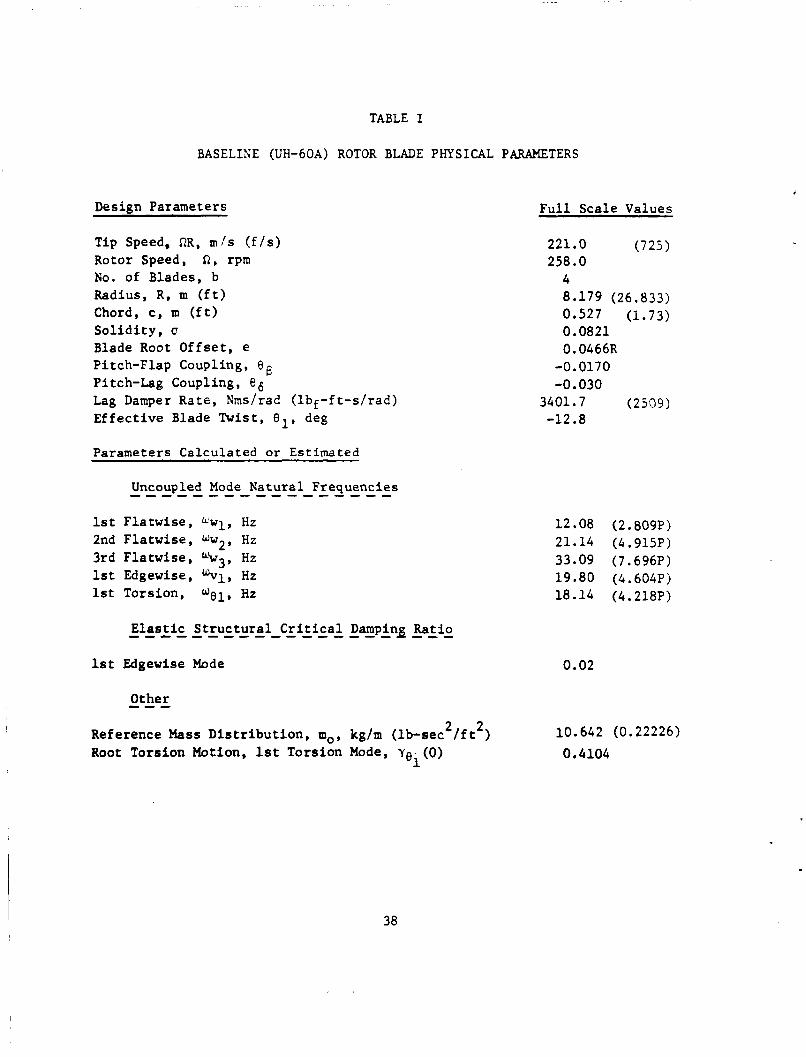
TABLE I
BASELIh’E (UH-60A) ROTOR BLADE PHYSICAL PARAMETERS
Design Parameters
Tip Speed, RR, m ! s (f/s) Rotor Speed, R, rpm No. of Blades, b Radius, R, m (ft) Chord, c, m (ft) Solidity, u Blade Root Offset, e Pitch-Flap Coupling, 8 Pitch-Lag Coupling, 86 Lag Damper Rate, Nms/rad (lbf-ft-s/rad) Effective Blade Twist, el, deg
Parameters Calculated or Estimated
1st Flatwise, uw1, Hz 2nd Flatwise, Ww2, Hz 3rd Flatwise, L’w3, Hz 1st Edgewise, %I, Hz 1st Torsion, Hz
Is t Edgewise Mode
Other --- 2 2 Reference Mass Distribution, mo, kg/m (lb-sec /ft )
Root Torsion Motion, 1st Torsion Mode, Ye. (0) 1
Full Scale Values
221.0 (725) 258.0 4 8.179 (26.833) 0.527 (1.73) 0.0821 0.0466R
-0.0170 -0.030
3401.7 (2509) -12.8
12.08 (2.809P) 21.14 (4.915P) 33.09 (7.696P) 19.80 (4.604P) 18.14 (4.218P)
0.02
10.642 (0.22226) 0.4104
38
.
1 2 3 4
.1434 ,1100 .loo0 .loo0
TA2LE I1
DISTRIBUTIONS OF GEOMETRIC AND MECHANICAL
PROPERTIES FOR BASELINE ROTOR BLADE
6 7 8 9
10 11 12 13 14 15
I .0500 .0500 ,0500 ,0500 .0500 ,0500 .0500 .0500 .0400 ,0100
,1183 ,2450 .3500 ,4500 .5250 ,5750 ,6250 .6750 ,7250 .7750 ,8250 .8750 .9250 ,9700 .9950
Case No.
1 2
.0186 3
.06447 ,06447 .06447 .06447 .06447 .06447 .06447 .06447 .06447 .06447 .06447 .06447 .06447 ,06447
Prop Force L i f t N (1bf) N(lbf) C L I U
VT 2 f 2 m/s(kts) m (ft 1
74.6(145) 2.54(27.4) 5275(1186) 77404(17401) 0.09314 90.0(175) 1.84(19.8) 5553(1248) 77404(17401) 0.09314
t l c
,0945 .0945 .0945 ,0945 .0955 .0955 .0955 .0955 .0955 .0955 .0955 .0950 ,0945 ,0945 .0945
n o c g T;; I -
3.0249 .9496 ,9638 .9683
1.0000 ,9779 .9903
1.0520 1.2324 1.2331 1.2270 1.4755 1.6298 1.2923 0.3784
-. 0001 -.0033 - -0033 - 0033 -. 0019 -. 0016 -. 0016 .0014 .0015 ,0015 ,0013 .0030
- . 0010 -. 0010 - .OOlO
,00570 .01320 .01340 ,01350 ,01360 .01370 ,01365 .01350 ,01440 .01466 .01470
.01410
.01340
.01390
01388
TABLE I11
SELECTED BASIC TRIM CONDITIONS FOR THE
U P 6 0 A BLACKHAWK ROTOR
39

Roll ing and p i t ck ing moments a r e each t o be trimmed t o zero with a to le rance of 4067 Nm (3000 lbf f t ) .
These bas i c t r i m ca ses were f u r t h e r expanded depending on t h e type, of op t iona l aerodynamic refinement included i n the c a l c u l a t i o n , For each f l i g h t speed, t h ree subcases were def ined as A, B, o r C i n accordance wi th the aero- dynamic d e s c r i p t i o n , r e spec t ive ly , being (A) quas i - s t a t i c a i r l o a d s , no v a r i a b l e inflow, (B) u n s t a l l e d unsteady a i r l o a d s , no v a r i a b l e inf low, and (C) uns t a l l ed unsteady a i r l o a d s , wi th (quasi) v a r i a b l e inflow. These t h r e e subcases were a l t e r n a t e l y used f o r gaging the appropr i a t e performance i n d i c e s of t he devices according t o the accuracy ref inements , r e spec t ive ly , requi red by each. The q u a s i - s t a t i c (A) subcases were used f o r t h e harmonically deformable t i p . The unsteady a i r l o a d s (B) subcases were genera l ly used f o r t he th ree t o r s i o n a l l y a c t i v e devices and the (C) subcases were used f o r i s o l a t e d c a l c u l a t i o n s f o r t he a l l - f l y i n g to r s ion t i p . For the (C) subcases, the v a r i a b l e inf low c a l c u l a t i o n s were performed using the UTRC Prescr ibed Wake Rotor Inflow Analysis (RIA) descr ibed i n Ref. 15.
The v a r i a b l e inflow da ta input t o G4OOPA were f i r s t ca l cu la t ed i n the R I A with a trimming procedure using the Table I11 values . By t h i s procedure, v a r i a b l e inf low da ta cons i s t en t wi th the trimmed condi t ions were obtained f o r use i n G400PA. It should be s t r e s s e d t h a t t h i s procedure r ep resen t s an a d hoc method f o r inc luding v a r i a b l e inf low i n the a e r o e l a s t i c code. The usua l , more r igorous method f o r inc luding v a r i a b l e inf low t y p i c a l l y r e q u i r e s a few i t e r a - t i o n s between the r o t o r inf low a n a l y s i s and the a e r o e l a s t i c code u n t i l convergence (consis tency) i s reached. This procedure, however, is q u i t e CPU t i m e i n t ens ive even without t he f u r t h e r onus of having t o t r i m t h e two analyses . Consequently, because of t h e l imi t ed resources a v a i l a b l e t o t h i s s tudy the here in ad hoc method was in s t ead used, i n hopes of ob ta in ing a t least a " f i r s t - cu t " i n d i c a t i o n of t h e e f f e c t s of v a r i a b l e inflow. To d i s t i n g u i s h the r e s u l t s obtained h e r e i n from those which would be obtained us ing t h e more r igorous procedure they a r e r e f e r r e d t o as "quasi" v a r i a b l e inf low r e s u l t s , It should be f u r t h e r s t r e s s e d t h a t t h i s ad hoc method f o r inc luding v a r i a b l e inf low would produce r e s u l t s which are approximately c o r r e c t In G400PA only at t h e r e spec t ive trimmed f l i g h t condi t ions .
Calculated Resu l t s
The r e s u l t s of t h e s i x t r i m c a l c u l a t i o n s are summarized i n Table I V and Figures 8 through 11. achieved ( t o be compared with r e spec t ive va lues from Table 111). General ly , t h e hub moments could be obtained t o wi th in t h e s e l e c t e d to l e rances only f o r
Table I V p re sen t s t h e actual hub f o r c e s and moment
40
the lower 145 k t f l i g h t condi t ion . Obtaining convergent trims a t the higher 175 k t f l i g h t .speed condi t ions was a c o n s i s t e n t l y d i f f i c u l t procedure through- o u t t h i s s tudy. i s bel ieved t o be r e l a t e d t o the increased ex ten t of s t a l l experienced on the r e t r e a t i n g blade s i d e a t t h i s f l i g h t speed, which thereby renders t h e t r i m p rocess h ighly nonl inear . Of p a r t i c u l a r usefu lness i n t h i s t a b l e are t h e base l ine va lues of l i f t pe r equiva len t drag, LID,, of median and &PTP roo t t o r s i o n moment, M, (0), and of t he 4P amplitudes of t he components of hub shea r s , Sxl, Syl, and Szl. Note t h a t t h e l i f t pe r equiva len t drag, LID,, accounts f o r requi red r o t o r power and is def ined as:
The d i f f i c u l t y experienced i n achieving sys temat ic convergence
5
L ‘Oe = 325.647 W / VT - PF
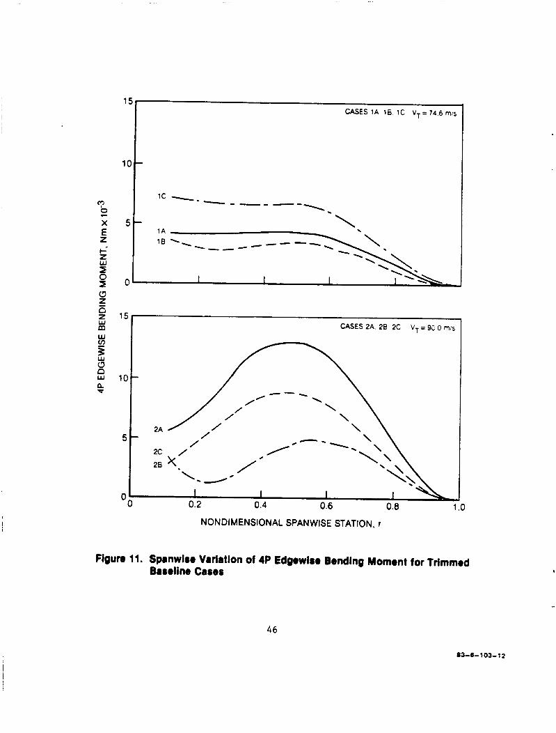
Table I V c l e a r l y shows t h e s t rong impact of v a r i a b l e inf low on LID,, median r o o t t o r s i o n moment, and 4P ver t ica l hub load ca l cu la t ions . F igures 8 and 9 show t h e %PTP f l a t w i s e and edgewise bending moments, r e spec t ive ly , f o r t h e s i x t r i m cond i t ions def ined i n Table I V . Since t h e %PTP va lues inc lude con t r i - bu t ions f rom all harmonics, F igures 10 and 11 p r e s e n t only t h e 4P ampli tudes of f l a t w i s e and edgewise bending moments, r e spec t ive ly , as an a l t e r n a t e b a s i s f o r i n t e r p r e t i n g and eva lua t ing the performance of t h e appended devices . In the subsec t ions t o fo l low t h e r e s u l t s w i l l be nondimensionalized, where poss ib l e , by t h e appropr i a t e base l ine va lues given i n e i t h e r Table I V o r Figure 8 through 11.
41
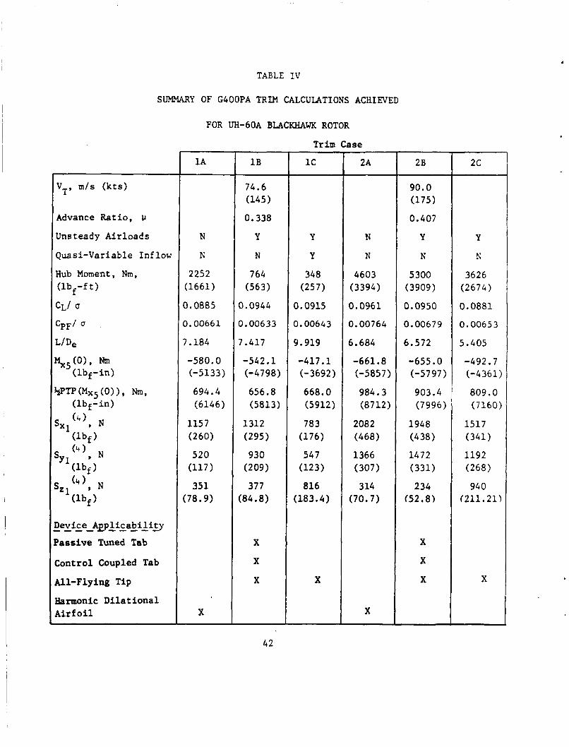
TABLE I V
SUMMARY OF G4OOPA TRIM CALCULATIONS ACHIEVED
FOR UH-60A BLACKHAWK ROTOR
Advance Ratio, u
Unsteady Airloads
Quasi-Variable I n f l o w
Hub Moment, Nm, (lbf-f t )
CLi u
‘PF’ ‘ L/D,
$5 :;:;-:) 9p 04x5 (0) 1 , h,
( l b f - i n )
(4), N
levice - - - - AEp&aiiliLy
?ass ive Tuned Tab
:ontrol Coupled Tab
Ul-Flying Tip
krmonic Di l a t iona l A i r fo i l
1 A
N
K
2252 (1661)
0.0885
0.00661
7.184
-580.0 (-5133)
694.4 (6146)
1157 (260)
520 (117 1 351
(78.9)
X
1 B
74.6 (145)
0.338
Y
N
764 (563)
0.0944
0.00633
7.417
-542.1 (- 47 98)
656.8 (5813)
1312 (295)
930 (209)
377 (84.8)
X
X
X
T r i m Case
1c
Y
Y
348 (25 7 1
0.0915
0.00643
9.919
-417 .1 (-3692)
668.0 (5912)
78 3 (176)
54 7 (123)
816 (183.4)
X
2A
N
N
4603 (3394)
0.0961
0.00764
6.684
-661.8 (-5857)
984.3 (8712)
2082 (468)
1366 (307)
314 (70.7)
X
2 B
90.0 (175)
0.407
Y
N
5300 (3909)
0.0950
0.00679
6.572
-655.0 (-57 97 )
903.4 (7996)
1948 (4 38 1 1 4 7 2 (331)
234 (52.8)
X
X
X
2c
Y
h’
3626 (2674)
0.0881
0.00653
5.405
-492.7 (-4361)
809.0 (7160)
1517 (341)
1192 (268)
94 0 (211.21)
X
42

c
20
CASES 1A. 1B. IC V T = 7 4 6 m/s
-
30 CASES 2A. 28. 2C VT = 90 0 mis
20
10 ’
2c 2A 28
I I I I 1 .o
0 0 0.2 0.4 0.6 0.8
NONDIMENSIONAL SPANWISE STATION, r
Figure 8. Spanwire Variation of 1IZPTP Fiatwise Bending Moment for Trimmed Baseline Cases
4 3
03-6- 103- 10
5c
4c
30
20
“b - X
z b- z w I 0 0 z
E ’0
I I I I OO 0.2 0.4 0.6 0.8 1
C A S E S l A 18 1C VT=746m/s
.o
‘\ \\
28 ’
‘\ \
\ CASES 2A. 2 8 2C V T = / - - \ /
/ 90.0 m/s
NONDIMENSIONAL SPANWISE STATION, r Figure 9. Spanwire Variation of 1lPPTP Edgewise Bending Moment for Trimmed
Basoline Cases 4 4
83-6103-11

CASES 1A. 18. 1C VT= 74 6 m/s 4 r
3 -
2 -
I I I
0.6 0.8 1 .o 0 0.2 0.4
NONDIMENSIONAL SPANWISE STATION, r
Figure 10. Spanwise Variation of 4P Flatwise Bending Moment for Trimmed Baseline Cases
45
1:
I C
5
0
CASES 1A, 18 IC VT = 74.6 m/s
\
I I I
’I 5
I I I I
0.2 0.4 0.6 0.8 1
NONDIMENSIONAL SPANWISE STATION, r
Figure 11. Spanwire Variation of 4P Edgewise Bending Moment for Trimmed Baseline Cases
46
83-6-103-12

Passive Tuned Tab
Background
The prel iminary development of t h i s device was performed using a sepa ra t e s impl i f i ed a e r o e l a s t i c a n a l y s i s which was only loose ly coupled with the G400PA a n a l y s i s (see Reference 16) . As descr ibed i n t h i s r e p o r t , t he b a s i s of t h e pas s ive tuned t a b was s imply conceptualized as shown i n Figure 1 2 . Generally, t h i s concep tua l i za t ion assumes t h a t the e f f e c t of t he t a b motion on the blade proper is l imi t ed t o t h e incremental a i r l o a d s der ived from the t a b motion. A s shown i n the f i g u r e , one incremental normal a i r l o a d resu!ts from an e f f e c t i v e camber induced s h i f t of t h e l i f t c o e f f i c i e n t f o r a f i x e d s e c t i o n angle-of-attack. The camber change a l s o c r e a t e s a s h i f t i n the blade p i t c h i n g moment c o e f f i c i e n t which i n t u r n c r e a t e s an a d d i t i o n a l a i r l o a d by tw i s t ing the blade t o c r e a t e a change i n the s e c t i o n angle-of-attack i t s e l f . When the t a b responds harmonically, the r e s u l t i n g incremental a i r l o a d s can add t o or s u b t r a c t from the inhe ren t (blade alone) a i r l o a d i n g depending on the amplitude and phase of t a b motion.
The e x c i t a t i o n of t he t a b w a s assumed t o be l i m i t e d t o t h a t induced i n e r t i a l l y by the blade as i t f l a p s (both as a r i g i d body and f l e x i b l y ) and p i t c h e s . The r o l e of t he G400PA a n a l y s i s i n t h i s s impl i f i ed t a b a n a l y s i s was t o provide the bas i c blade a e r o e l a s t i c responses used t o e x c i t e t he tab . The f i n a l harmonic hub shea r s can then be ca l cu la t ed using the incremental t a b loads (both i n e r t i a l and aerodynamic) together with those p red ic t ed by the G400PA a n a l y s i s .
An example of t h e v e r t i c a l hub shear loads as p red ic t ed by t h i s s impl i f i ed a n a l y s i s f o r t he Blackhawk r o t o r i s presented i n Figure 13 ( taken from Reference 16) . i d e n t i f i e d t h e p o t e n t i a l f o r t h i s device. As r epor t ed i n t h i s r e fe rence , the i n t e r p r e t a t i o n of t h e Figure 13 r e s u l t s are as follows:
It is the favorable f i n d i n g s r epor t ed i n th i s r e fe rence t h a t
"TO study t h e e f f e c t i v e n e s s of t h e pas s ive tuned tab , a b a s e l i n e t a b conf igu ra t ion w a s s e l e c t e d and v a r i a t i o n s i n t a b design parameters from the b a s e l i n e conf igu ra t ion was selected and v a r i a t i o n s i n t a b design parameters from t h e b a s e l i n e conf igu ra t ion were inveat igated. . .
Placement of t he t a b along t h e blade span is c r i t i c a l f o r t a b e f f e c t i v e n e s s . This i s shown i n Figure (13). shown as a func t ion of t a b spanwide l o c a t i o n f o r a t a b with l eng th equivalent t o 1 C pe rcen t of t h e blade r a d i u s . and lO/rev. The t a b l o c a t i o n f o r maximum e f f e c t i v e n e s s is between 50 and 70
The p red ic t ed v i b r a t o r y r o o t v e r t i c a l shea r s a r e
Resu l t s are shown f o r two t a b tunings: 5 / r ev
4 7

-
t W cn Z
v) W
W
g a
Q W cn C
K
z 5
-T-
48 00-12-29-1
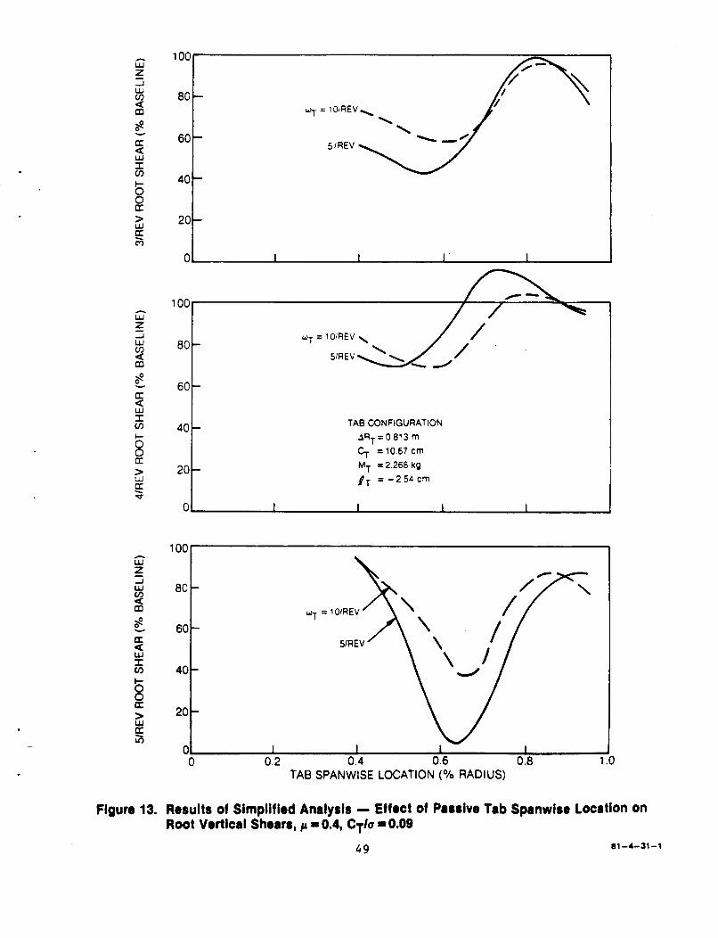
iii z 2 W a 3
5
6 B
8 - U.
I cn
> W K 3
A
W
-J w a
z
s U. W I cn
a
5 B 2 E v
W z W
3 e 4 K
I cn
's a 5 5
Figure 13.
40
208
2o t
I
6o t TAB CONFIGURATION
3RT = 0.81 3 m 5 =10.67cm
pT = - 2 5 4 c r n M~ = 2.268 kg
01 I 1 I I
TAB SPANWISE LOCATION ('lo RADIUS)
Results of Simplified Analysis - Effect of Passive Tab Spanwise Location on Root Vertical Shears, p L: 0.4, CT/U = 0.09
81-4-31-1 4 9

percent blade r a d i u s . This r e s u l t is a t t r i b u t e d d i r e c t l y t o the in f luence of the f l a t w i s e mode shapes on the e x c i t a t i o n of t he tab. Both f irst and second f l a t w i s e modes have ant inodes i n t h i s r eg ion , and s i n c e the t a b is i n e r t i a l l y exci ted by the blade f la twise motion, more e x c i t a t i o n occurs a t f l a t w i s e antinodes than a t f l a t w i s e nodes. The node p o i n t s f o r these same two f l a t w i s e modes a r e between 75 and 90 percent and Figure 1 3 shows t h a t t h i s i s the region of lowest t a b e f f e c t i v e n e s s . I n f a c t , ampl i f i ca t ion of the 4Irev r o o t v e r t i c a l shea r s a l s o occurs i n t h i s region. The blade t i p i s a l s o an ant inode f o r the blade f l a t w i s e modes but Figure 13 shows t h a t e f f e c t i v e n e s s f o r a t a b loca ted a t the blade t i p i s n o t as good as f o r a t a b near midspan. The reason f o r t h i s apparent anomaly i s related t o the in f luence of t he r i g i d body f l a t w i s e mode on t a b e x c i t a t i o n . Even though the r i g i d body f l a t w i s e mode c o n t r i b u t e s l i t t l e t o the r o o t v e r t i c a l shea r , i t s motion is apprec iab le a t 3, 4 , and 5/rev. I n f a c t , t he r i g i d body f l a t w i s e mode has more motion a t 3, 4 , and 5 / r ev than the second f l a t w i s e mode (~ '"5.1 r e v ) . The in f luence of the r i g i d body mode on the t a b e x c i t a t i o n i s t h e r e f o r e de t r imen ta l because the t a b responds t o n u l l the v e r t i c a l shear caused by the v e r t i c a l motion. From t h i s i t i s clear t h a t , based on the r i g i d body f l a t w i s e mode shape, an inboard t a b l o c a t i o n i s b e t t e r than an outboard t a b l o c a t i o n in order t o reduce the t a b response t o the r i g i d body mode. For example, a t m i d span the r i g i d body f l a t w i s e mode shape has only half the d e f l e c t i o n a t the blade t i p , so t he in f luence of t h e r i g i d body f l a t w i s e mode on the t a b response is a l s o cu t i n h a l f .
Figure 1 3 a l s o shows t h e e f f e c t of t a b tuning on the v i b r a t o r y r o o t v e r t i c a l shears . Overall, the 5 p e r rev tuning provides b e t t e r v i b r a t i o n a l l e v i a t i o n than the 10 per rev tuning. This is because t a b angular motion inc reases wi th a decrease i n t a b n a t u r a l frequency, and increased t a b motion provides increased c o n t r o l a u t h o r i t y . For a t a b loca ted a t 60 pe rcen t r a d i u s wi th a 5 / r ev tuning, t he percent reduct ions i n v i b r a t o r y shea r s are 54, 15, and 88 percen t f o r 3, 4 and S/rev, r e s p e c t i v e l y . However, t h e t a b angular motions a s soc ia t ed wi th t h i s l e v e l of r o o t shear r educ t ion may v i o l a t e design c o n s t r a i n t s . "
Limitat ions of Simglif ied Analysis - - - - - - - - - ----- -- A s a r t i c u l a t e d i n a n above subsec t ion , t h e s i m p l i f i e d a n a l y s i s omits two
forms of blade-to-tab coupling: t o blade motion, and t h e i n e r t i a e x c i t a t i o n of t h e blade proper due t o t h a t motion, The la t ter type of coupling i n l a r g e measure d e f i n e s t h e e l a s t o - mechanical "pendular absorber" dynamics which t h e t a b imposes on t h e blade because of i t s mass. A p o t e n t i a l l y weak element of ,$he s i m p l i f i e d a n a l y s i s is t h e ad hoc combining of some c a l c u l a t i o n s of t h e (nonl inear) G400PA c a l c u l a t i o n s with those of t h e ( l i n e a r ) e impl i f i ed t a b equat ions. l i m i t a t i o n of t he forced response s i m p l i f i e d a n a l y s i s is t h a t i t only o b t a i n s
the aerodynamic e x c i t a t i o n o f t he t a b due
A major
50
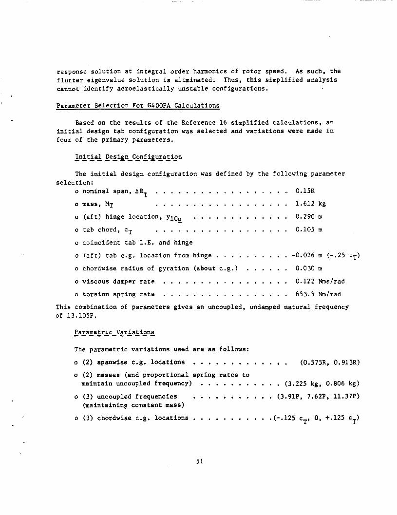
response solution at integral order harmonics of rotor speed. As such, the flutter eigenvalue solution is eliminated. Thus, this simplified analysis cannot identify aeroelastically unstable configurations.
Parameter Selection For GOOOPA Calculations
Based on the results of the Reference 16 simplified calculations, an initial design tab configuration was selected and variations were made in four of the primary parameters.
Initial Desip Configuration ------ - - - - - - The initial design configuration was defined by the following paraneter
o nominal span, ART . . . . . . . . . . . . . . . . . . 0.15R selection:
o mass, MT . . . . . . . . . . . . . . . . . . 1.612 kg
o tab chord, cT . . . . . . . . . . . . . . . . . . 0.105m o (aft) hinge location, y1oH . . . . . . . . . . . . . 0.290 m
o coincident tab L.E. and hinge
o (aft) tab c.g. location from hinge . . . . . . . . . . -0.026 m (-.25 CT)
o chordwise radius of gyration (about c .g .1 . . . . . . 0.030 m o viscous damper rate . . . . . . . . . . . . . . . . . 0.122 Nms/rad o torsion spring rate . . . . . . . . . . . . . . . . . 653.5 Nm/rad
This combination of parameters gives an uncoupled, undamped natural frequency of 13.105P.
Parametric Variations - - - - - - - - - - The parametric variations used are as follows:
o (2) spanwise c.g. locations . . . . . . . . . . . . . (0.5751, 0.913R)
o (2) masses (and proportional spring rates to maintain uncoupled frequency) . . . . . . . . . . . (3.225 kg, 0.806 kg)
o (3) uncoupled frequencies . . . . . . . . . . . (3.91P, 7.62P, 11.37P) (maintaining constant mass)
o (3) chordwise c.g. locations . . . . . . . . . . .(-.125 cT, 0, +.125 cT)
5 1

1 2
1 .o
1.0
0.8
- -- - 0.8 E
' I
-
0.6
04
0 2
0
1 2
1 I I I
1 0 - 1
L
I I I I
"E 0.2
TAB SPANWISE LOCATION
10 5R - 0 65R) - - - (0 a 5 ~ - 0 97%)
0
12
10
8
6
4
2
0
1 I I I I I 1
t 0 1 4 5
Figure 14. Variations in Components of 4P Hub Shear with Passive Tuned Tab Mass, 90 mls Flight Speed (u =0.4) 5 2
83--6103-1

1.2
1 .o
I I I
1.2
1 .o
0.8
0.6
0.4
0.2
0
12
10
a
6
4
2 1 0 I I I I I
0 5 10 15 20
TAB FREQUENCY, +, PER ROTOR REV
25
Figure 15. Variations in Components of 4P Hub Show with Passivo Tuned Tab Uncoupled
5 3
Tab Frequency, 90 mls Flight Speed (p =0.407)
0 3 - 6 1 03-6

tk
Figure 16.
1 .i
1 .c
0.e
0.6
0.4
0.2
0
I
0.E
0.4
0.2
01 I I 1 I 1
12
i o
8
6
4
2 1 0 I 1 I I I 4.3 4.2 -0.1 0 0.1 0.2 0.3
(ND) TAB C.G LOCATION FROM HINGE, Y&C T
Variations in Compononts of 4P Hub Shear with Passive Tuned Tab Mass Center Location, 90 mls Flight Sped (cc 00.4)
54 83-6-1 03-7
Generally, the results are cons i s t en t ly poor. While some modest ga ins ( reduct ions i n v i b r a t o r y shear) a r e noted f o r t he longi tudina l and la te ra l component p red ic t ions , t h e major i nc reases i n t h e ver t ical component would c l e a r l y be unacceptable. Note t h a t because of the ex ten t of t hese counter- product ive r e s u l t s , o the r lesser parameters which could have been va r i ed , such as t ab chord and f l i g h t speed, were not . v a r i a t i o n s d id n o t r e s u l t i n a design enhancing predic t ion , t he resources of t h i s s tudy were d i r ec t ed t o more product ive purposes.
Since the major parameter
The reason f o r t h e highly counter-productive r e s u l t s a c t u a l l y obtained, i n view of the o p t i m i s t i c r e s u l t s from the s impl i f i ed a n a l y s i s , is no t f u l l y understood, however. One p o s s i b l e explanat ion is that the t ab , a t these parameter va lues , is opera t ing as a badly mistuned pendular absorber . Another reason is t h a t t he proper, more f u l l y coupled a n a l y s i s of t h i s device (as afforded by the G400PA a n a l y s i s ) r equ i r e s a more d e t a i l e d accounting of a l l t h e va r ious balancing f o r c e s and moments than t h e s impl i f i ed ana lys i s i s capable of . These ques t ions , however, are beyond t h e scope of the present study.
Control Coupled Tab
I n i t i a l Parameter Se lec t ion f o r GOOOPA Calcula t ions . . . . . . . . . . . . . . . . . . . . - - - - - Because of the high degree of mechanical s i m i l a r i t y between the con t ro l
coupled t a b (CCT) and the pas s ive tuned t a b (PTT), t he nominal design configu- r a t i o n se l ec t ed f o r t he CCT w a s the same used for t h e PTT. The t a b was loca ted a t t h e outboard p o s i t i o n ( rCG -0.913R) and the minimum mass (.806 kg), T zero c.g. o f f s e t conf igura t ion was used throughout. Of t h e remaining p r i n c i p a l parameters impacting on the CCT, the blade roo t t o r s i o n s t i f f n e s s , KgR, (as
def ined by c o n t r o l system s t i f f n e s s ) , and the c o n t r o l coupl ing gain, GT were
se l ec t ed f o r major parameter variation. S p e c i f i c a l l y , v a r i a t i o n s i n Kg were
se l ec t ed t o y i e l d uncoupled b lade t o r s i o n f requencies , ue,, of 2.25P, 3.19P and
4.73P (compared wi th 4.22P f o r t h e base l ine conf igu ra t ion ) . t i o n s i n coupling ga in , GT, were determined by matching i n nondimensional u n i t s
t h e dimensional ga in v a r i a t i o n s used i n Reference 16 (0, -.00885, and -.01770 deg/Nm) .
R - The se l ec t ed var ia -
I n c o n t r a s t t o t h e i n t e n t of t he pass ive tuned tab , t h e " tab alone" dynamics of t he CCT about i t s hinge are no t germaine t o i t s ope ra t ion and, hence, should be i s o l a t e d from t h e dynamics due t o coupling. Accordingly,
55

the spr ing r e s t r a i n t of the t a b t o t h e coupling attachment was set t o a su i t ab ly high va lue t o i n s u r e t h a t t he uncoupled t ab frequency, weT, would
be i n excess of 2OP. The a c t u a l va lue achieved was 26.7P. Since t h e c o n t r o l loads would be expected t o be a func t ion of t h e trim condi t ions , i t w a s concluded that a l l c a l c u l a t i o n s f o r t h e CCT would n e c e s s i t a t e t he use of t h e t r i m procedure.
-
G4OOPA Calcula t ion Resul t s - - - - - - - - - - - - - Using the parameter s e l e c t i o n s t r a t e g y def ined above, i n i t i a l c a l c u l a t i o n s
were made with combinations of r o o t t o r s i o n s t i f f n e s s and the r e s u l t i n g va lues of coupling gain. I n every in s t ance , i t w a s found t h a t t r i m c a l c u l a t i o n s could not be achieved due t o gross l o s s e s of r o t o r l i f t . I n an a t t e m p t t o shed l i g h t on t h i s phenomenon, non-trim c a l c u l a t i o n s were made f o r s i m p l e p e r t u r b a t i o n s of the coupling ga in , GT = - + 0 . 5 (deg/deg) with the nominal roo t t o r s i o n s t i f f n e s s , These t rends are presented i n t h e form of p a r t i a l d e r i v a t i v e s of va r ious p e r t i n e n t performance parameters wi th respec t t o coupling ga in , GT.
Parameter
TABLE V
PARTIAL DERIVATIVES OF PERFORMANCE PARAMETERS
W I T H RESPECT TO COUPLING GAIN FOR CONTROL
COWLED TAB, p = 0.338
CT/ LIDe
Nm
N
N
N
a (Parameter) / a G T
Dimensional Value
,00943
0.403
- 8 .71
-231.3
- 57.8
- 1.4
% Basel ine
10.4
5.6
-1.2
-7 :2
-4.4
-0.2
56
The p r i n c i p a l r e s u l t t o be gleaned from Table V is that, f o r the t a b geometry used, the device is funct ioning almost exc lus ive ly as a generator of a d d i t i o n a l r o t o r l i f t rather than a s a r e l i e v e r of v i b r a t i o n a l push-rod loads . Su rp r i s ing ly , t he p o t e n t i a l f o r changes i n v i b r a t i o n a l push-rod load l e v e l per coupling ga in is n o t only q u i t e low i n magnitude ( r e l a t i v e t o the l i f t change p o t e n t i a l ) , but is of the opposi te s i g n from what would normally be expected based on t h e f ind ings of Reference 16.
Two explanat ions have been i d e n t i f i e d f o r t he disagreement of t h e p re sen t f i nd ings with those of Reference 16:
1. The conf igu ra t ion used he re in has t w i c e t h e t a b c h o r d / a i r f o i l chord r a t i o as t h a t used i n Reference 16 (20% vs. 10%). The twofold inc rease i n t h i s r a t i o should have a comparable inc rease i n Acg, but t he accompanying increase i n A%
because of the shortening of moment arm. Indeed, for f l a t p la te theory i n the l i m i t of u n i t chord r a t i o , t he increment i n moment c o e f f i c i e n t approaches zero.
should be r e l a t i v e l y less c / 4
2 . The c a l c u l a t i o n f o r incremental moment due t o t a b d e f l e c t i o n used he re in was made using the a n a l y t i c formulat ion of Theodorsen and Garr ick (Reference l o ) , whereas t h a t used i n Reference 16 was made using experimental va lues as given i n Reference 17. f a c t t h a t t h i s experimental d a t a was l imi t ed t o a chord r a t i o of no t more than 0.10, t he experimental d a t a source would have been a b e t t e r a l t e r n a t i v e than the a n a l y t i c one used. Within the context of t he unsteady a i r l o a d s methodology adapted h e r e i n , however, t h e i n c l u s i o n of such experimental s t a t i c data would result i n an ad hoc formulation r equ i r ing some engineer ing judgment.
Except f o r t he
One observat ion which can be made of t he CCT is t h a t aeromechanically i t bears a s t rong resemblance t o t h e Kaman servo-tab r o t o r system. concept a t a b is used t o produce blade t o r s i o n a l moments f o r t h e purpose of r o t o r c y c l i c c o n t r o l . the CCT, t h e aerodynamic p r i n c i p l e invoked is t h e same: t o r s i o n moment c o n t r o l using a t r a i l i n g edge tab. development can be assumed t o be reasonably optimized, t h e t a b is of small chord r a t i o and loca ted an exaggeratedly a f t d i s t a n c e so as t o be removed from the blade proper e n t i r e l y . aerodynamic moment generat ion while minimizing the incremental l i f t generat ion.
I n t h a t r o t o r
Although t h e i n t e n t is somewhat d i f f e r e n t from t h a t of
I n t h e Kaman system, which a f t e r several yea r s of
This conf igu ra t ion would c l e a r l y maximize t h e incremental
57
Thus, f o r purposes of the CCT, the se l ec t ed t ab conf igura t ion is f a r from optimal and a complete eva lua t ion of t h i s concept would r equ i r e an Optimization study of the design parameters. This add i t iona l opt imizat ion s tudy , w a s beyond the resources of the present s tudy.
All-Flying Torsion T r i p
Prel iminary Analysis
I n i t i a l G400PA c l c u l a t i o n s were made f o r t h e a l l - f l y i n t o r s i o n t i p using q u a s i - s t a t i c a i r l o a d s and a s t ra ight-forward implementation of a nominal s e l e c t i o n of t i p dynamic parameters. t he bas i c b lade (without t i p ) was a 95% reduct ion i n mass d i s t r i b u t i o n over the t i p span reg ions where the t i p was t o be loca ted . Thissubt rac tedmass w a s then included i n the t i p mass desc r ip t ion . With these se l ec t ed dynamic parameters , the c a l c u l a t i o n s uncovered a number of problem areas. the concept necessa r i ly e n t a i l s o f f s e t s of the t i p aerodynamic cen te r from both the hinge a x i s and t h e mass center . Nominally, t he m a s s c e n t e r would be located co inc ident wi th the hinge ax is .
Included i n input parameters f o r
As shown i n F igure 3,
Prel iminary c a l c u l a t i o n s were made using the nominal conf igu ra t ion rrLth the aerodynamic c e n t e r maintained a t the q u a r t e r chord poin t . This r e s u l t s i n a s i g n i f i c a n t forward mass cen te r c o n s i s t e n t wi th a placement of t h e t a b hinge a x i s 1 2 % of the chord i n f r o n t of t he blade p i t c h ( e l a s t i c ) a x i s . I n t h i s conf igura t ion , severe o s c i l l a t i o n s were ca l cu la t ed which were subsequently a sce r t a ined t o be f l u t t e r involving the second f l a t w i s e bending and f i r s t t o r s i o n modes. the hinge l i n e (and mass cen te r ) were co inc ident wi th t h e e l a s t i c ax i s . This conf igu ra t ion was found t o be s t a b l e and convergent responses were thereby achieved.
A temporary f i x f o r t h i s condi t ion w a s t o d i sp l ace the t i p a f t so t h a t
Subsequent a t tempts t o r e t u r n t o t h e o r i g i n a l conf igura t ion , wi th t h e forward t i p mass c e n t e r , were eventua l ly success fu l ly made. The s t a b i l i z a t i o n of t h i s o r i g i n a l conf igura t ion was achieved by ad jus t ing t h e mass c e n t e r s of blade segment numbers 2, 7 and 11 t o n u l l t he i n e r t i a l coupling of t h e second f l a t w i s e bending and t o r s i o n modes. It i s of interest t o note that t h e aero- mechanical s t a b i l i t y a n a l y s i s o f Chopra (Reference 18), whi le p r e d i c t i n g some low frequency i n s t a b i l i t i e s a s soc ia t ed wi th r i g i d f lapping and lead-lag motions, does no t p r e d i c t o r a n t i c i p a t e t h i s e s s e n t i a l l y classic bending-torsion f l u t t e r . Probable reasons f o r t he discrepancy i n f ind ings of t he p re sen t work wi th those
58
of Reference 18 are t h a t the present a n a l y s i s included the a e r o e l a s t i c equat ions f o r e las t ic modes, a t i p hinge a x i s d i sp laced from t h e e l a s t i c a x i s , and used r ea l i s t i c amounts of damping, both s t r u c t u r a l and t h a t from the lead- l a g damper, i n t he ca l cu la t ions . The ana lys i s of Reference 18, however, u s e d a s impl i f i ed modeling without e l a s t i c i t y d i r ec t ed t o t h e f lap- lag- tors ion i n s t a b i l i t y problem, and considered no s t i f f n e s s r e s t r a i n t t o t h e f r e e t o r s i o n sect ions.
A second d i f f i c u l t y experienced i n t h e pre l iminary c a l c u l a t i o n s w a s t h a t t he expected inc rease i n L/De d id n o t m a t e r i a l i z e wi th t h e device a c t i v a t e d even wi th s u f f i c i e n t (cons tan t ) appl ied moment about t h e t i p axis t o main ta in p o s i t i v e l i f t on the advancing s ide . I n these c a l c u l a t i o n s , no at tempt was made t o retrim t h e r o t o r and t h e c o n t r o l s e t t i n g s and inf low va lues appropr i a t e t o t h e trimmed unappended blade were used d i r e c t l y . I n t h i s condi t ion , t he cons tan t appl ied moment was found t o be aggrava t ing t h e s t a l l condi t ion on t h e r e t r e a t i n g blade s i d e of t h e r o t o r d i s k , thereby inc reas ing t h e equiva len t drag
De. obtained, however, only when the r o t o r w a s r e t r i m e d .
It w a s subsequently found t h a t t h e p o t e n t i a l f o r increased LIDe could be
Addi t iona l pre l iminary c a l c u l a t i o n s were performed t o e s t a b l i s h t r ends wi th regard t o t h e i n t e r p l a y between t h e o f f s e t appl ied (zero d e f l e c t i o n ) t o r s i o n moment and t h e t o r s i o n sp r ing rate. The r e s u l t s of t hese c a l c u l a t i o n s are shown i n F igures 17 t h r u 19. Figure 17 presen t s t he b a s i c t r ends achieved wi th sepa ra t e v a r i a t i o n s i n o f f s e t moment and sp r ing ra te . p o i n t s i n t h i s f i g u r e (denoted by t h e square symbols) d e f i n e t h e range of mean t i p d e f l e c t i o n ang le s achieved toge ther with t h e r e s u l t i n g average equi l ibr ium ( i n e r t i a l and aerodynamic) loading moments, MEQUIL . The equilibrium loading moment i s a d i r e c t measure of t h e s teady l i f t sus ta ined on t h e b lade s e c t i o n s comprising t h e t i p . r e l a t i v e i n s e n s i t i v i t y of t h e performance i n d i c a t o r (L/De) t o o f f s e t moment, %, and t h e s t r o n g s e n s i t i v i t y t o s p r i n g rate, Kg . shown i n t h e f i g u r e i s t h e small v a r i a t i o n i n equilibrium loading wi th o f f s e t moment. mean t i p d e f l e c t i o n angle,
The four c a l c u l a t i o n
The p r i n c i p a l f i n d i n g presented by t h i s f i g u r e i s t h e
A r e l a t e d secondary r e s u l t
The o f f s e t moment is seen t o a f f e c t p r i n c i p a l l y only t h e v a l u e of t h e
*TO
Figure 18 p r e s e n t s t h e r e s u l t s achieved by l i n e a r l y ganging t h e o f f s e t moment and sp r ing rate so t h a t a l l combinations would tend t o e q u i l i b r a t e a t a s e l e c t e d t i p d e f l e c t i o n ang le and equi l ibr ium loading moment. s e l e c t e d f o r F igure 18 are, r e spec t ive ly , -1.07 degrees and 381 Nm. With
The va lues so
5 9

751
70(
65C
60C E
+- z z
0 r Z
550
0 g 500 e a_ +
450
400
350
4 0
VT = 90.0 mls (r = 0 407)
M ~ ~ ~ t ~ = M ~ + K ~ T DP,
Jl
- K = 11524 NmlRAD - - - t T = 3 3 9 0 NmlRAD
M, = 691
'EQUILIBRIUM LOADING MOMENT, MEOUIL
1 I I I I I I -0.8 -0.6 -0.4 -0.2 0 -1.6 -1.4 -1.2 -1 .o
MEAN TIP DEFLECTION, + , deg 0
Figun 17. Effects of Offset Momont and Sphng Rat0 on Opontion of Ail-Flying Tip-Preliminary Analysis
60

E a-
I 0 I z m U
z c 2
0
e a I-
650
600
550
500
2000 4000 6000 8000 ’ 10000 12000 14000 0
TIP TORSION SPRING RATE, K , NmlRAD BT
Figure 18. Effect of Linearly Combined Offset Moment and Spring Rate on Equilibrium Loading Moment for All.Flying TipPreliminary Analysis
61 - -
83-6-1 03-1 5
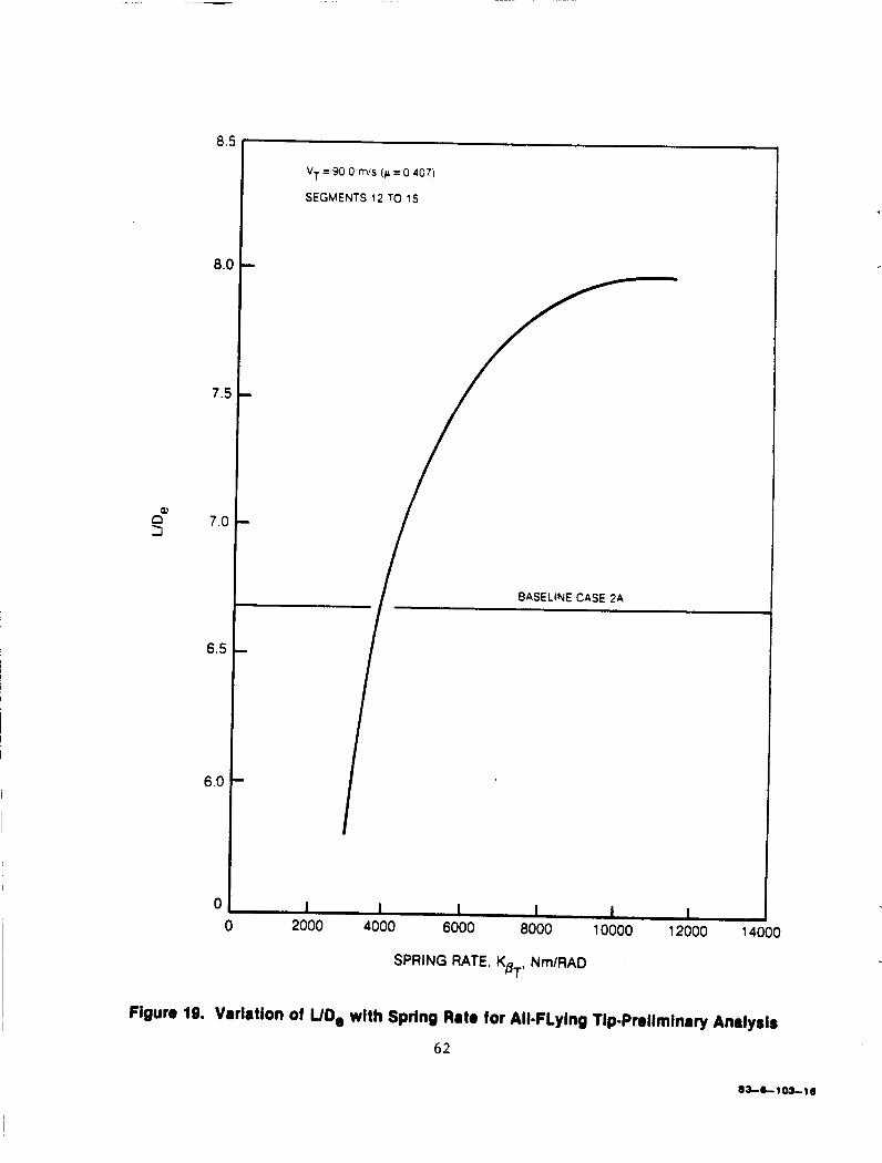
8.5
8.0 I
I VT = 90 0 m/s (F = 0 407)
SEGMENTS 12 TO 15
SPRING RATE, K NmlRAD BT'
Figure 19. Variation of UD, with Spring Rate for Ali=FLying TipPreiiminrty Analysis
62
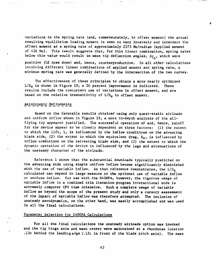
?
v a r i a t i o n s i n the sp r ing ra te (and, commensurately, i n o f f s e t moment) the a c t u a l r e s u l t i n g equi l ibr ium loading moment is seen t o vary inve r se ly and i n t e r s e c t the o f f s e t moment a t a sp r ing ra te of approximately 2373 Nmlradian (appl ied moment of 426 Nm). This r e s u l t suggests t h a t , f o r t h i s l i n e a r combination, sp r ing rates below t h i s value would r e s u l t i n mean t i p d e f l e c t i o n angles , BT,, which were
p o s i t i v e (LE nose down) and, hence, counterproductive. I n a l l o t h e r c a l c u l a t i o n s involving d i f f e r e n t l i n e a r combinations of appl ied moment and sp r ing ra te , a minimum sp r ing rate was gene ra l ly defined by the i n t e r s e c t i o n of t he two curves.
The e f f e c t i v e n e s s of t h e s e p r i n c i p l e s t o ob ta in a more nea r ly optimized L/De i s shown i n Figure 19; a 20 percent improvement is ind ica t ed . r e s u l t s include the concurrent use of v a r i a t i o n s i n o f f s e t moment, and are based on the r e l a t i v e i n s e n s i t i v i t y of LIDe t o o f f s e t moment,
These
Aerodynamic Refinements - - - - - - - - - - - Based on the favorable r e s u l t s obtained using only q u a s i - s t a t i c a i r l o a d s
and uniform inf low shown i n Figure 19, a more in-depth a n a l y s i s of the a l l - f l y i n g t i p appeared j u s t i f i e d . f o r the device appear t o be c l o s e l y dependent on t h r e e f a c t o r s : (1) the e x t e n t t o which the l i f t , L, is inf luenced by t h e inflow cond i t ions on the advancing blade s i d e , (2 ) the ex ten t t o which the equivalent drag, De, i s inf luenced by inf low cond i t ions on the r e t r e a t i n g blade s i d e , and (3) t he e x t e n t t o which the dynamic ope ra t ion of the device i s influenced by t h e l a g s and a t t e n u a t i o n s of t h e unsteady cha rac t e r of t h e a i r l o a d s .
The success fu l ope ra t ion of and, hence, payoff
Reference 1 shows t h a t t he s u b s t a n t i a l downloads t y p i c a l l y predicted on the advancing s i d e using simple uniform inf low become s i g n i f i c a n t l y diminished with the use of v a r i a b l e inflow. ca l cu la t ed can depend i n l a r g e measure on t h e o p t i o n a l use of v a r i a b l e inf low or uniform inflow. For use w i t h t h e GOOOPA, however, t h e r igo rous usage of v a r i a b l e inflow i n a combined t r i m i t e r a t i o n program i n t e r a c t i o n a l mode i s extremely computer CPU t i m e i n t ens ive . inflow as beyond the scope of the p re sen t s tudy and only a cursory assessment of t h e impact of v a r i a b l e inf low was t h e r e f o r e attempted. unsteady aerodynamics, on t h e o t h e r hand, w a s e a s i l y accomplished and was used i n a l l t h e f i n a l c a l c u l a t i o n s .
A s t h a t r e fe rence demonstrates, the L/De
Such a complete usage of v a r i a b l e
The i n c l u s i o n of
Parameter S e l e c t i o n f o r G400PA Calcu la t ions
For all t h e f i n a l c a l c u l a t i o n s t h e unsteady a i r l o a d s op t ion w a s invoked and the t i p hinge a x i s and mass c e n t e r were maintained a t a chordwise l o c a t i o n .13c behind the leadingedge (.12c i n f r o n t of t h e blade p i t c h a x i s ) , The mass
63

of each of t he t i p s e c t i o n s w a s chosen t o be approximately 95% of the cor res - ponding unappended blade s e c t i o n mass. The parameter v a r i a t i o n s used i n the f i n a l c a l c u l a t i o n s are as follows:
o t o r s i o n sp r ing rate: (W14000 Nm/rad) o moment c o n s t r a i n t r e l a t i o n between o f f s e t moment and sp r ing ra te :
(Mg = 381 + .0187 K B ~ ,
267 + e0187 K B ~ )
o spanwise ex ten t : * ( O . l O R , 0.15R) o f l i g h t a i r speed: (74.6, 90.0 m/s)
I n add i t ion , f o r t he best conf igura t ion obtained from t h e parameter v a r i a t i o n s , t he approximate e f f e c t s of v a r i a b l e inf low were inves t iga t ed f o r the two f l i g h t speeds.
G400PA Calcula t ion Resu l t s
The ca lcu la t ed r e s u l t s f o r t he a l l - f l y i n g t i p c o n s i s t predominantly of a s i n g l e performance index: l i f t t o equiva len t drag r a t i o ( see Equation 19 ) . For i s o l a t e d condi t ions , r e s u l t s a r e a l s o presented f o r 1/2PTP blade bending and t o r s i o n moment d i s t r i b u t i o n s . Generally, the c a l c u l a t i o n procedure def ined i n t h e above Prel iminary Analysis Subsection i s adhered to . The r e s u l t s are presented i n Figures 20 th ru 32.
E f f e c t s a t Unsteady Air loads - - - - - - - - - - - - - Figure 20 compares the p red ic t ed L/De v a r i a t i o n s w i t h r e s t r a in t s t i f f n e s s
as made wi th and without t h e e f f e c t s of unsteady a i r l o a d s f o r t he high speed (p 0.407) f l i g h t cond i t ion and the 15% r a d i u s t i p span conf igura t ion . The comparison appears t o be reasonably c l o s e wi th no s i g n i f i c a n t changes i n charac te r . l a t i o n discussed above are maintained and even improved upon w i t h t h e inc lus ion of unsteady a i r l o a d s . On a percent improvement over base l ine b a s i s , t h e impact of unsteady a i r l o a d s appears t o be advantageous.
The favorable g a i n s obtained wi th a q u a s i - s t a t i c a i r l o a d s fonnu-
* Note t h a t t h e corresponding t i p masses are: (11.32 kg, 13.07 kg)
64
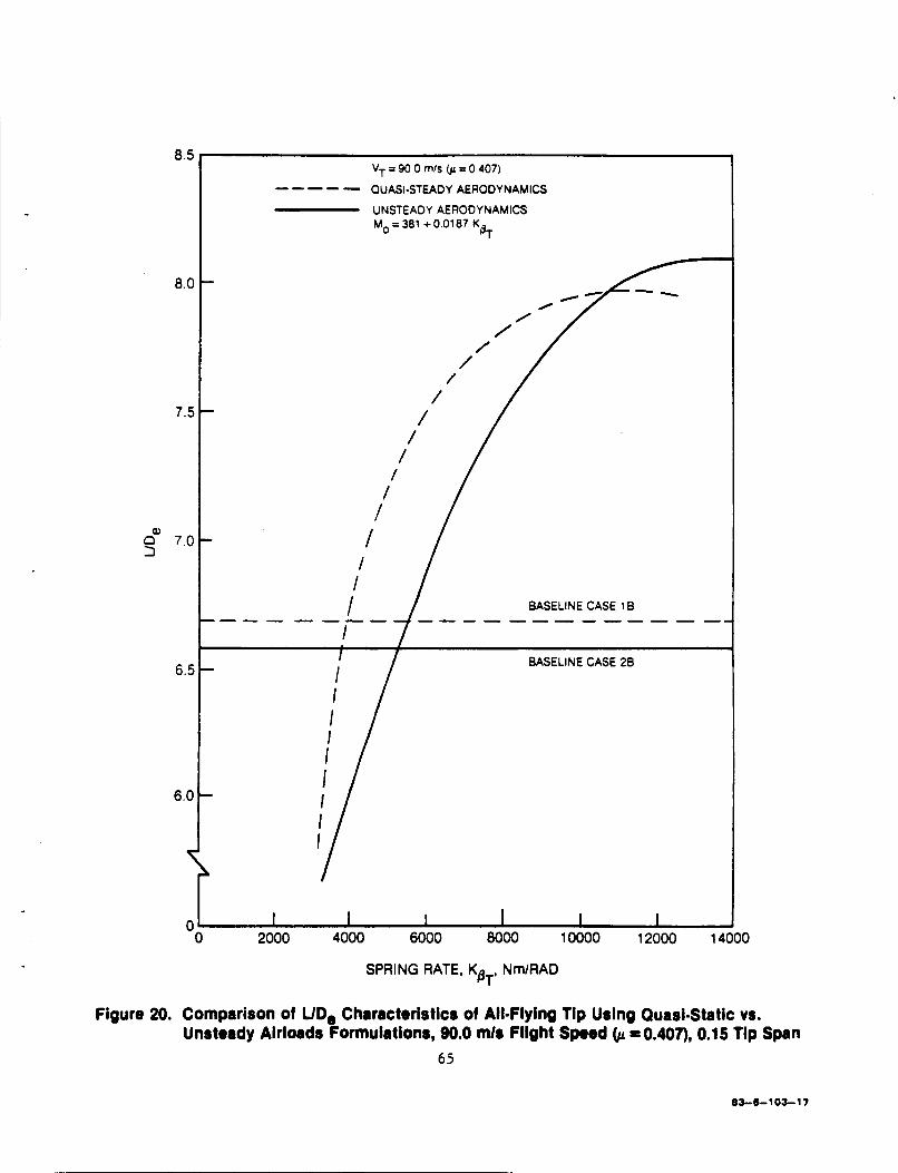
8.5
8.0
7.5
a2 0 7.0 3
6.5
6.0
VT = 90 0 m k 01 = 0 407)
----- OUASI-STEADY AERODYNAMICS
UNSTEADY AERODYNAMICS Mo = 381 + 0.01 87 K a,
I 1
/ /
/ /
- /
/
I I I I Y 0 I I I I I I 0 2000 4000 6000 8000 10000 12000 14000
SPRING RATE, K NmlRAD BT'
Figure 20. Comparison of UD, Characteristics of All=Flying Tip Using Quasi-Static vs. Unsteady Airloads Formulations, 90.0 mla Flight Sped =0.407), 0.15 Tip Span
65
83-6-103-17

Performance c h a r a c t e r i s t i c s f o r the reduced span (.10R) a r e presented i n
The reduced Figures 2 1 and 22. t o the v a r i a t i o n i n the o f f s e t moment schedule wi th sp r ing rate. value of o f f s e t moment a t zero sp r ing rate, 267 Nm, corresponds t o t h a t f o r t he 15% span r a t i o e d by the areas weighted by r2 . reduced o f f s e t moment i s seen t o occur a t the low sp r ing rate cond i t ions , wherein the g r e a t e s t d i f f e rences i n equi l ibr ium moment and s teady t i p def lec- t i o n s would occur. obtained a t sp r ing rates wherein the equi l ibr ium moments are very nea r ly equal . The r e s u l t s shown i n Figure 22 confirm the expec ta t ion t h a t the lower (area sca led) appl ied moment would produce a more near ly optimal performance index than would the moment appropr i a t e t o the 15% span conf igura t ion . F igures 21 and 22 a l s o show the optimum L/De va lues t o occur a t s i m i l a r va lues of e q u i l i - brium moment.
The pr imary comparison made i n these f i g u r e s is wi th regard
The p r i n c i p a l e f f e c t of t he
As Figure 22 shows, however, the maximum LID, va lues are
- - - - - Reduced F lakt-SEe - e d
Figure 23 c o n t r a s t s the equi l ibr ium moments obtained f o r each of the two spanwise conf igura t ions (10% and 15% span) a t the two f l i g h t speeds. General ly f o r e i t h e r spanwise ex ten t t he t r ends are similar, i n t h a t t h e h igher e q u i l i - brium moment occurs a t the h igher f l i g h t speed. As would be expected, the 15% span conf igura t ion would opera te a t a commensurately h igher equi l ibr ium moment. Figure 24 p re sen t s a summary of t he b e s t c a l c u l a t i o n s f o r t h e two spanwise ex ten t conf igu ra t ions each a t t h e two f l i g h t speeds.
Figures 25 th ru 28 p resen t t ime-history responses of t he t i p s e c t i o n s f o r va r ious o f f s e t moment/spring r a t e schedules , t i p spans and f l i g h t speeds. Figures 25 and 26 each compare the responses r e s u l t i n g from va r ious s p r i n g rates (and concomitant o f f s e t moments) a t the same high speed f l i g h t cond i t ions (p .407) but f o r t h e 15% and 10% t i p spans, r e spec t ive ly . show t h e s u b s t a n t i a l o s c i l l a t o r y c h a r a c t e r i s t i c s of t h e t i p a t the lower sp r ing rates and t h e subsequent s t a b i l i z a t i o n induced by the h igher sp r ing rates. The f igu re8 a l s o g raph ica l ly show the nega t ive peaks which occur a t the JI- 90 advancing b lade p o s i t i o n , r e f l e c t i n g t h e requi red ope ra t ion of t he t i p i n augmenting t h e a i r l o a d i n g i n t h i s po r t ion of t h e r o t o r d i sk . Note t h a t t h e higher o s c i l l a t o r y conten t i n responses f o r t he lower sp r ing rates gene ra l ly allow p o s i t i v e ( leading edge down) d e f l e c t i o n excursions and an over ly negat ive peak a t t h e 90 deg azimuth pos i t i on . Both of t hese excessive response
Both these f i g u r e s
66
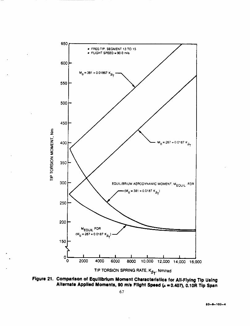
6501 600
550
500
450
E z i Z w I 0 I z v,
I-
c
E! 8 &
-
-
-
-
FREE-TIP. SEGMENT 13 TO 15 FLIGHT SPEED = 90 0 mls /
400 1 -/ / Mo=267.r00187 Kj,
- / \ EOUlLlBRlUM AERODYNAMIC MOMENT M,,, ,,, FOR
(M,=267+00187 K ) J
0 2000 4000 6000 8000 10,000 12,000 14,000 16.000
TIP TORSION SPRING RATE. K Nmlrad BT'
Figure 21. Comparison of Equilibrium Moment Characteristics for All-Flying l i p Using =0.407), O.iOR l i p Span Alternate Applied Moments, 90 mls Flight Speed
67
83-6 103-4

8.C
7.5
7.c
Q, s 6.!
FREE-TIP. SEGMENT 13 TO IS FLIGHT SPEED. VT = 90.0 mls
4 / / - M,=381 +0018667 K
I 1 I I I I 10,000 12,000 14,000 16,000
0 400 0 6000 8000
TIP TORSION PRING RATE, KsT, Nm/rad
Figure 22. Comparlson of UD, Characteristics of All=FlyIg Tip Using Alternate Offset Moment Schedules, p = 0.407,O.lOR Tip Span
68
- - - - - - FREE-TIP, SEGMENT 12 TO 15. M,=381 +00187 K
FREE-TIP, SEGMENT 13 TO 15 , M, =267 + 0.0187 K dT BT
450 1
I I I I 0'
H 300
E z b- z
0 r" 74.6 m/s 1
2501 2oo t
\
I 74.6 mls - -,------
TIP TORSION SPRING RATE, KB , Nmlrad T
Figure 23. Comparison of Equilibrium Moment Characteristics of All=Flylng Tip for Alternate Flight Speeds and Tip Spans
69
83-6-103-2

1'
I I I I I I I I I I 0 2000 4000 6000 8000 10,000 12,000 14,000 16,000 18000 20000 22000
1c
9
- BASELINE (TIP LOCKED UP)
-- FREE-TIP. SEGMENT 12 TO 15. M,=381 +00187 K
BT
81
--- FREE-TIP. SEGMENT 13 TO 15, M, = 267 + 0.0107 K
Figure 24. Comparison of UD, Characteristics of All-Flying Tip for Alternate Flight Speeds and Tip Spans
70
B L b l O 3 - 9

! *\
,yo-
(. / *
''t.c.. \
\ 1 I
d I N
71
83-8-61 -3
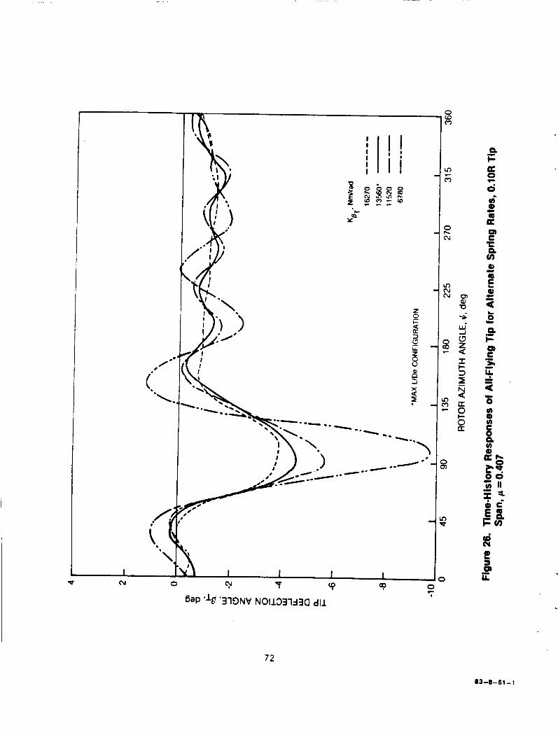
E cu
m N N
0 aD c
m (3 -
8
Ln P
3
72
83-8-61 - 1

/ \
I I I I ? T P
6aP ' lo ' '319NV NO11331330 d l l
7 3
83-8-61 -4

/ I
6ap 'l&f '319NV N01133133Q dl l
7 4
83-8-61 -2

features would detract from conditions favorable to optimum L/De: of local lift due to positive tip deflection and increase in equivalent L/De: in equivalent drag due to too high an angle-of-attack on the advancing side. Generally, the observed trends shown in Figure 25 for the 15% tip span carry over to the 10% tip span responses shown in Figure 26. these figures are the tip responses for the maximum L/De configurations. Each of these optimal responses are characterized by a well-damped signature, a negative peak at the 90 degree azimuth position and a generally negative mean value of about 1 deg. for the remainder of the rotor period. Figures 27 and 28 show the variations of the tip time-history responses with flight speed for the 15% and 10% tip span optimal configurations, respectively. For both of these spanwise extent configurations, the same spring rate (K =13560 Nrn/rad)
was used. attributed to (1) a higher natural frequency (resulting from a reduced torsion inertia) and ( 2 ) a reduction in aerodynamic damping (resulting from a reduced aerodynamic area and the less effective airloading of the tip sections). Generally, the response characteristics of the tip section are not strong functions of flight speed.
reduction
reduction of local lift due to positive tip deflection and increase
Included on both of
BT The higher oscillatory content in the 10% span responses can be
Tig Section Ankle-of-ALtack Dnamic Characteristics - - - - - - - - - - - - - - - - - - - - - - Figures 29 and 30 present the time-histories of the effective angle-of-
attack, u
the center section of the 15% tip span configuration), f o r the two flight conditions, u= 0.338 and 0.407, respectively. In each of these figures are (1) the appropriate baseline results (no tip), (2) the results for the tip section activated but responses with the increment due to tip motion arti- ficially subtracted out, and (3) with the tip motion included. clearly show the reductions in negative angle-of-attack at the advancing blade portions of the disk provided by the device. blade proper responses with the tip activated are even more negative than the baseline values in this portion of the disk. response characteristic is the blade's response to the reaction moment imparted by the tip device.
characteristics of the T = 0.925 radial station (corresponding to E'
The responses
The figures also show that the
A probable reason for this
Observations and Interzretations ----------- ---- Observations which can be made from the non-variable inflow results are
as follows:
75

' I I I I '
N 0 c c
83-8-61 -5
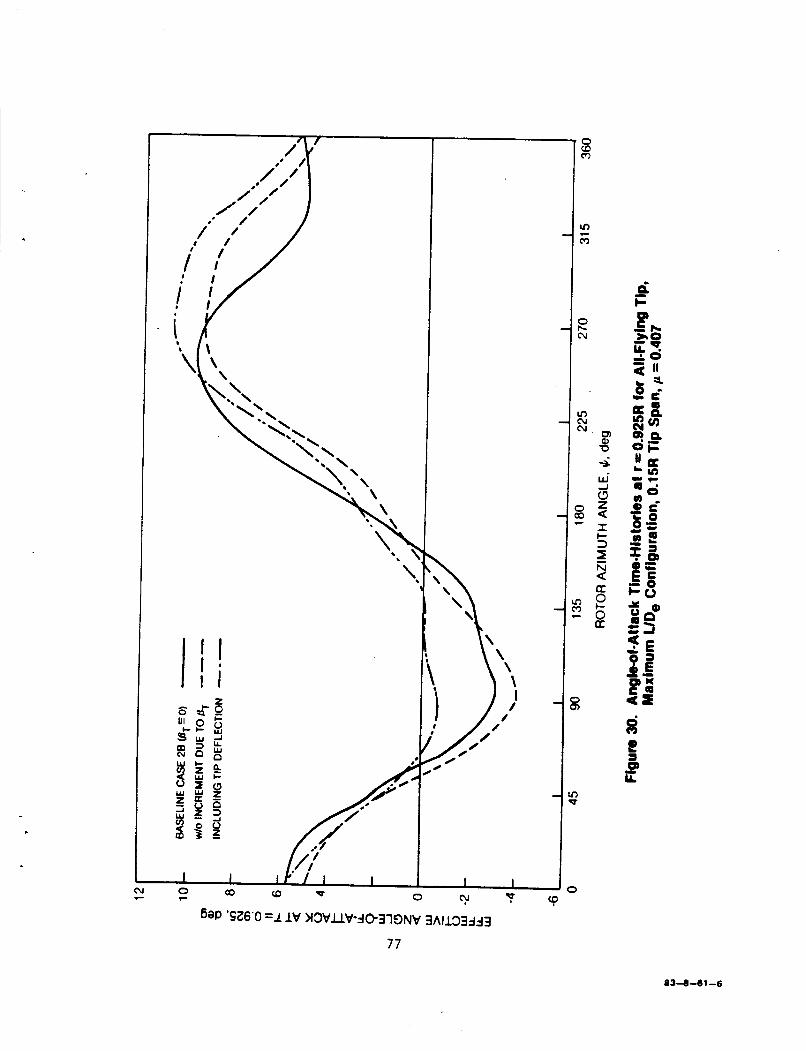
83-8-61 -6

1.
2.
3.
4 .
5.
6 .
The inc rease i n performance obtained f o r t he device t r acks the performance v a r i a t i o n wi th respect t o a i r speed f o r t he unappended device.
The e f f e c t of increased t i p span on performance i s a monotonic func t ion of t h e t i p span.
The sp r ing ra te f o r maximum LIDe v a r i e s wi th f l i g h t speed; t h e off-optimum pena l ty does n o t appear g r e a t , however.
The maximum performance ga ins f o r t h e device (again neglec t ing v a r i a b l e inf low f o r t h e moment) are approximately 20% f o r t he 0.15R conf igu ra t ion and 10% f o r t h e 0.10R conf igura t ion .
The opera t ion of t he device i s t r u l y dynamic i n t h a t i t n o t only provides a more o r less s teady inc rease i n angle-of-attack over most of t he r o t o r azimuth, but wi th an incremental dynamic peak where i t i s most needed on t h e advancing blade po r t ions of t he aximuthal per iod.
Off-optimal responses a t the reduced sp r ing rates are cha rac t e r i zed by excess ive o s c i l l a t o r y motion.
As discussed i n an above subsec t ion , t he v a r i a b l e inf low d i s t r i b u t i o n s appropr ia te t o trimmed f l i g h t a t t h e two f l i g h t speeds were c a l c u l a t e d and input t o GOOOPA, without interprogram i t e r a t i o n . These d i s t r i b u t i o n s were used t o provide a pre l iminary estimate of t h e e f f e c t of v a r i a b l e inf low on one c l o s e l y optimized conf igura t ion . General ly , t h e r e s u l t s ob ta ined wi th the use of quas i -var iab le inf low are suspec t . Comparison of t r i m cases 1 B wi th l C , and 2B wi th 2C shows a d e t e r i o r a t i o n i n t h e incremental performance due t o v a r i a b l e inf low where t y p i c a l l y t h e reverse i s t h e norm. r e s u l t s f o r t h e r o t o r wi th t h e s e l e c t e d optimized a l l - f l y i n g t i p conf igu ra t ion , a t t he two advance r a t i o s , both showed s u b s t a n t i a l aerodynamic ga ins : va lues w e l l i n excess of 10. The most v a l i d observa t ion t o be drawn from these r e s u l t s i s t h a t t h e t r u e e f f e c t of v a r i a b l e Inf low on t h e performance of t h e a l l - f l y i n g t i p i s moot and r e q u i r e s a more r igo rous i n c l u s i o n of t h i s methodology.
On t h e o t h e r hand,
L/De
F igures 31 and 32 p resen t comparisons of i n t e r n a l v i b r a t o r y blade loads f o r a conf igu ra t ion s e l e c t e d f o r b e s t L/De a t t h e two f l i g h t speeds. t r ends from these r e s u l t s are as fol lows:
Discernable
78

.
1
5.c
4.c
CL i 2.0
2 0 'I
k g
1 .o
0
m
WITH TIP ACTIVATED BASELINE CASE IC -----
-
1 .o ------ - -
2'ol , u.2
0 1 0 0.4 0.6
NONDIMENSIONAL SPANWISE STATION, r
Figure 31. Vibratory Blade Bending and Torsion Moment Characteristics for All-FLying lip, 0.15R Tip Span, p r0.338, Maximum UD, Conditions
79

3.0 I
m z o g 2.0 5 5 c
5.0
-
4.0 L /
#
/-- \ 0 \
/ \ \ .
/ I
TED WITH TIP ACTIVA BASELINE CASE 28 -----
1.0 - 0 1 1 1
NONDIMENSIONAL SPANWISE STATION,T
.
I I I
Figure 32. Vibratory Blade Bending and Tonion Moment Characteristics for All-Flying Tip, 0.15R Tip Span, 1 - 0.407, Maximum UDe Conditions
80
83-6-103-20

o The p r i n c i p a l impact of t he device on the 1 / 2 PTP f l a t w i s e bending moment d i s t r i b u t i o n i s the l o c a l i nc rease j u s t inboard of the device attachment. This would be expected based on the increased loading of t he t i p s e c t i o n s .
o Apar t from the t i p regions the device produces n e g l i g i b l e inc reases , where inc reases are noted, i n t h e bending moments.
o The 1/2 PTP t o r s i o n moments are, as would be expected, r e l a t i v e l y unaffected by t h e ope ra t ion of the device.
Harmonically D i l a t i o n a l A i r f o i l Tip
The aeromechanical ope ra t ion of the Harmonically D i l a t i o n a l A i r f o i l T i p (HDAT) is assumed t o be more benign than those f o r the t o r s i o n a l l y a c t i v e devices , which are p o t e n t i a l l y s u s c e p t i b l e t o aeromechanical and/or a e r o e l a s t i c i n s t a b i l i t y . In t h e absence of test, no known i n s t a b i l i t i e s can be l inked with the HDAT a t t h i s time. Consequently, the GOOOPA c a l c u l a t i o n s f o r t h i s device pose no s p e c i a l cons ide ra t ions and a r e r e l a t i v e l y r o u t i n e . is aerodynamic performance r e l a t e d and, hence, a l l G400PA c a l c u l a t i o n s gene ra l ly r e q u i r e t r i m computations.
The device
Parameter Se lec t ion f o r G400PA Calculat ions
The G400PA c a l c u l a t i o n s of t he HDAT u t i l i z e a i r f o i l aerodynamic d a t a look-ups based on thickness r a t i o in s t ead of r a d i a l s t a t i o n . The th i ckness r a t i o n d i s t r i b u t i o n for t h e base l ine (UH-60A) h e l i c o p t e r r o t o r blade i s given i n Table 11. This d i s t r i b u t i o n based on the SC1095 a i r f o i l series is gene ra l ly cons t an t and r e f l e c t s a c u r r e n t t rend t o cambered, r e l a t i v e l y th inne r s e c t i o n s . For success fu l ope ra t ion of t he HDAT, the a i r f o i l must c o n t r a c t t o as t h i n a s e c t i o n as is p o s s i b l e on the advancing side and commensurate d i l a t i o n must be implemented on t h e r e t r e a t i n g blade s i d e .
The p r i n c i p a l parameter s e l e c t i o n r equ i r ed f o r t he G400PA XDAT c a l c u l a t i o n s t h e r e f o r e cons i s t ed of a c q u i r i n g and preparing f o r G400PA inpu t aerodynamic a i r f o i l d a t a a t a v a r i e t y of t h i ckness r a t i o s . a i r f o i l used t o c o n s t r u c t t h e required a i r f o i l d a t a t ab le :
The following t a b l e lists the
81
Thickness Rat io A i r f o i l
0.080 . . . . . . . . RC-08 0.0945 . . . . . . . . SC1095 0.0955 . . . . . . . . SC1095/R8 0.120 . . . . . . . . sc1012 0.150 . . . . . . . . NACA 0015
Note t h a t t he th ickness r a t i o range thus a v a i l a b l e i n d i c a t e s t h a t more d i l a t i o n a l range (.0945+.15) is a v a i l a b l e than con t r ac tua l (.0945+.08). Thus, the t o t a l th ickness r a t i o s ca l cu la t ed assuming a harmonic pe r tu rba t ion were t runcated t o minimum and maximum values of .08 and .15, r e spec t ive ly .
The parameter v a r i a t i o n s used i n the G4OOPA c a l c u l a t i o n s are as fol lows:
o amplitude of pe r tu rba t iona l thickness r a t i o s , A T / C . . . (0+.06) o r o t o r azimuth angle f o r minimum thickness r a t i o s , JI (70 , 90, 110 Ceg)
‘/emin o spanwise ex ten t : * * (0.10R, 0.15R)
o f l i g h t a i r speed: . . . . . . . . . . . . . . . . . . . (74.6, 90.0 m / s )
G400PA Calculat ion Resul t s
The appropr i a t e performance index f o r the DHAT as f o r t h e a l l - f l y i n g t i p i s the l i f t pe r equiva len t drag r a t i o , L/De, (see Equation 19) . The c a l c u l a t i o n
results f o r t he DHATarepresented i n Figures 31 and 32. comparisons of t he LID, with v a r i a t i o n s i n t h e parameters discussed above.
These f i g u r e s show the
The resu l t s shown i n F igures 33 and 34 confirm t h e expected r e s u l t t h a t the HDAT is capable of increas ing the aerodynamic performance of h e l i c o p t e r r o t o r s i n forward f l i g h t . S p e c i f i c observa t ions and i n t e r p r e t a t i o n s of t hese r e s u l t s are as follows:
1. Maximum performance ga ins i n L/De of approximately 11% and 9% are indica ted a t t h e ~ 0 . 3 3 8 and 0.407 advance r a t i o s , r e spec t ive ly .
2. The maximum performance ga ins occur, as would be expected, f o r configura- t i o n s wi th a minimum th ickness aximuth angle of 90 deg. ( f u l l advancing blade condi t ion) .
82

VT=9COmls(r=0407)
BASELINE CASE 2A I
6.0 6'1 l R T $,,, T I C . deg 0 15R 90 0 15R 110 - - - 015R 70
- - - - - - - _ - _ _ _
01 I I I I I 0 0.1 0.2 0.3 0.4 0.5 0.6
AMPLITUDE OF A r k
Figure 33. Variation of UD, Characteristics of Harmonically Dllational Tip with Amplitude of Perturbational Thickness Ratio, O.15R Tip Span, p -0.407
a3
8 3 - 6 1 03-19

aJ s
8.5
8.0
7.:
7.c
6.5
7.E
7.(
6.:
6.C
VT t 74 6 mls @ = 0.338)
u
f (b) VT = 90.0 m/s (p = 0 407)
\ BASELINE CASE 2A
I I I I I 0.01 0.02 0.03 0.04 0.05 c
AMPLITUDE OF Ark
.
16
Figure 34. Comparison of UD, Characteristics of Harmonically Dllational Tip for Variations In Flight Speed and Tip Span
a4
83-6- 1 03- 1 8
! .
I '
3 . The maximum performance ga ins occur a t p e r t u r b a t i o n a l t h i ckness r a t i o amplitudes of .03 t o .035.
4 . The ga in i n performance between 0.10R and 0.15R t i p span conf igu ra t ions is i n excess of what would be expected from the r a t i o of t i p areas. One p o s s i b l e explanat ion of t h i s r e s u l t i s t h e secondary ga ins obtained from the increased thickness on the r e t r e a t i n g blade s i d e .
CONCLUSIONS AND RECOMMENDATIONS
An a n a l y t i c s tudy has been performed of t h e p r a c t i c a l i t y of fou r d i f f - e r e n t pas s ive a e r o e l a s t i c devices appended t o h e l i c o p t e r r o t o r blades f o r improving r o t o r aerodynamic performance, reducing c o n t r o l loads and/or a l l e v i a t i n g a i r f r ame v i b r a t i o n . the v a l i d i t y of t h e conclusions is heavi ly dependent on the accuracy of the modeling assumptions employed and on the depth of the s tudy performed h e r e i n ,
Since t h i s study was s t r i c t l y a n a l y t i c ,
Conclusions
General Assessment of Devices
1.
2 .
3.
. 4.
The pass ive tuned t a b as configured i n t h i s study is imprac t i ca l . This is based on the s i g n i f i c a n t l y amplif ied 4P v e r t i c a l hub shear loads and t h e r e l a t i v e l y small a t t e n u a t i o n s achieved i n the l o n g i t u d i n a l and l a t e r a l loads.
The c o n t r o l coupled t a b as configured i n t h i s s tudy i s imprac t i ca l . This is based on t h e r e l a t i v e l y excessive incremental r o t o r l i f t changes p e r coupling gain (and consequently tab d e f l e c t i o n ) obtained as compared with the incremental blade t o r s i o n moment changes forming the b a s i s of t h i s device.
The a l l - f l y i n g t i p o f f e r s t h e p o t e n t i a l f o r s i g n i f i c a n t i n c r e a s e s i n aerodynamic performance. P resen t f i n d i n g s p r o j e c t an approximately 20% inc rease i n LID, f o r t h i s device wi th no s i g n i f i c a n t i n c r e a s e s i n blade bending o r t o r s i o n moments.
The harmonically d i l a t i o n a l a i r f o i l t i p o f f e r s t he p o t e n t i a l f o r moderate i n c r e a s e s i n aerodynamic performance. approximately 10% inc rease i n L/De f o r t h i s device.
P resen t f i n d i n g s p r o j e c t an
85

5 . Favorable f ind ings f o r t he a l l - f l y i n g t i p and the harnonica l ly d i l a t i o n a l a i r f o i l t i p should be a d d i t i v e t o a s i g n i f i c a n t degree. the former device achieves performance ga ins by e l imina t ing performance robbing i n e f f i c i e n c i e s i n l i f t (notably r o t o r areas of negat ive l i f t , whereas the l a t t e r device achieves ga in by reducing l o s s e s accruing from drag rises due t o advancing blade compress ib i l i ty .
This is because
Spec i f i c Conclusions Rela t ing t o Device Operation
1.
2 .
3 .
4 .
5 .
6 .
1.
For both performance r e l a t e d devices (a l l - f l y ing t i p and d i l a t i o n a l a i r f o i l t i p ) t he ga in i n performance a r i s i n g from increased t i p span is i n excess of t h e inc rease I n t i p a rea . A poss ib l e explanat ion is t h a t the increase i n area occurs a t the inboard, aerodynamically more e f f i c i e n t end of the t i p .
The b e n e f i t s from the devices a r e not monotonic with f l i g h t speed and a r e gene ra l ly more optimal a t the moderate advance r a t i o (~30.3 t o 0,35) f l i g h t speeds than a t t h e high advance r a t i o ones.
The e f f e c t s of unsteady a i r l o a d s do no t d e t r a c t from the ga ins i n aero- dynamic performance predic ted f o r t h e a l l - f l y i n g t i p .
The r e s u l t s from the use of a quas i -var iab le inf low procedure were inconclusive.
The i n c l u s i o n of unsteady aerodynamics i s c r i t i c a l t o a s a t i s f a c t o r y modeling of t he t o r s i o n a l l y a c t i v e devices for purposes of p red ic t ing a e r o e l a s t i c i n s t a b i l i t y ( f l u t t e r ) .
A l l implementations of t o r s i o n a l l y a c t i v e devices on a b lade should be configured such t h a t t h e combined blade is appropr i a t e ly configured wi th chordwise mass balancing t o decouple c r i t i c a l f l a t w i s e and t o r s i o n modes and thereby preclude f l u t t e r .
Recommendations
Any f u t u r e work t o r e f i n e t h e assessment of the pass ive tuned t a b should be d i r e c t e d t o parameter v a r i a t i o n s on an a c t i v e implementation of the harmonic t a b responses t o e s t a b l i s h what amplitudes and phases of those responses , i f any, a c t u a l l y a t t e n u a t e the v i b r a t o r y hub loads.
86

2 , A rigorous interactional calculation, using the G4OOPA and Rotor Inflow Analysis (RIA) Programs should be made for the all-flying tip to more fully assess the impact of variable inflow on the improved L/De predictions for this device. the kinematics of the dynamic response of the all-flying tip.
This would require modification of the RIA to include
3. Additional parameter variations, with regard to hinge location and the geometry of aerodynamic sweep should be made for the all-flying tip.
4. The detailed dynamic modeling and evaluation of an implementation for passive excitation of the dilational airfoil tip should be made. This evaluation would indicate (1) how practical and obtainable the ideal response is, and (2 ) what potential aeromechanical instabilities might exist for this device.
5 . A study should be made to detennine the extent to which the gains of the all-flying tip and the harmonic dilational airfoil tip are additive.
6. Future work on the control coupled tab should be directed to tab config- urations which maximize the section moment/lift characteristics such as a nonattached tab located as far aft of the balde section proper as is practical.
r
87

REFERENCES
'. 1. Blackwell, R. H.: Investigation of the Compliant Rotor Concept.
USMlRDL Technical Report 77-7, June 1977,
2. Ruddell, A. J. : Advancing Blade Concept (ABC)m Development. Proceedings of the 23rd Annual National Forum of the American Helicopter Society, May 1976.
3. Wernicke, K. G.: Performance and Safety Aspects of the VX-15 Tilt Rotor Research Aircraft. Proceedings of the 33rd Annual National Forum of the American Helicopter Society, May 1977.
4 . Gabel, R.: Pendulum Absorbers Reduce Transition Vibration. Proceedings of the 31st Annual National Forum of the American Helicopter Society, May 1975.
5.. Stroub, R. H: Performance Improvements With the Free-Tip Rotor. Proceedings of the Specialists' Meetings on Rotor System Design of the American Helicopter Society, Philadelphia, PA., October 1980.
6. Bielawa, R. L.: Aeroelastic Analysis for Helicopter Rotor Blades With Time-Variable, Nonlinear Structural Twist and Multiple Structural Redundancy - Mathematical Derivation and Program User's Manual. NASA Contractor Report CR-2638, October 1976.
7. Houbolt, J. C. and G. W. Brooks: Differential Equations of Motions for Combined Flapwise Bending, Chordwise Bending, and Torsion of Twisted
' Nonuniform Rotor Blades. NACA Report 1346, 1958.
8 . Bielawa, R. L.: Blade Stress CalculaEions - Mode Deflection vs. Force Integration. J. of the American Helicopter Society, Vol. 24, No. 3, July 1978.
9. Bielawa, R. L.: Aeroelastic Analysis for Helicopter Rotors With Blade Appended Pendulum Vibration Asorbers -- Mathematical Derivations and Program User's Manual. NASA CR-165896, June 1982.
e 10. Theodorsen, T. and I. E. Garrick: Nonstationary Flow About a Wing- Aileron-Tab Combination Including Aerodynamic Balance. Report 736, 1941.
NACA Technical
89
P R a J D e 3 G PAGE BLANK NO!I' FILMED

11. Bielawa, R. L., S. A. Johnson, R. ti. Chi, and S. T. Gangwani: Aeroelastic Analysis for Propellers - Mathematical Formulation and Program User's Manual. NASA CR-3729, December 1983.
12. Bisplinghdff, R. L., H. Ashley, and R. L. Halfman: Aeroelasticity. Addison-Wesley Publishing Co., Inc., Reading, MA., 1955, pp 281-286.
13. Reissner, E.: Effect of Finite Span on the Airload Distributions f o r Oscillating Wings, Vol. I - Aerodynamic Theory of Oscillating Wings of Finite Span. NACA TN 1194, March 1947.
14. Rowe, W. S., J. D. Sebastian, and M. C. Redman: Recent Developments in Predicting Unsteady Airloads Caused by Control Surface Notions. J. of Aircraft, Vol. 13, No. 12, December 1976, pp 955-961.
15. Egolf, T. A. and A. J. Landgrebe: A Prescribed Wake Rotor Inflow and - Flow Field Prediction Analysis - User's Manual and Technical Approach.
NASA CR 165894, June 1984.
16. Blackwell, R. H., et al.: Predesign Study for an Advanced Flight Research Rotor. Sikorsky Aircraft Report SER-510105, NASA CR-166405, December 1982.
17. Prouty, R. W.: A State-of-the-Art Survey of Two-Dimensional Airfoil Data, Journal of the American Helicopter Society, Vol. 20, No. 4, October 1974, pp 14-25.
18, Chopra, I.: Dynamic Analysis of Constant-Lift and Free-Tip Rotors. J. of the American Helicopter Society, Vol. 28, No. 1, January 1983.
90

1. R m t No. NASA CR166525
3. R u p . n t ' s cnrlog No 2. Covunmont L o n No.
Analy t i c I n v e s t i g a t i o n of He l i cop te r Rotor Blade Appended A e r o e l a s t i c Devices
4 Tclo md Subtitlo 1. O.tr
9 Rforning Olgll)imtMn Nrmr rd Mdrrs
United Technologies Research Center East H a r t f o r d , CT 06108
7. AuthorW
Richard L. Bielawa
11 -ut or Grrnt No NAS2-11008
0. Worming Orvirrtion A ~ p o r t No
R84-915774-24 10. Work Unit No.
1 : Soornoring bqmcv ND~M md A d d r a
NASA-Ames Research Center Mof fe t t F i e l d , CA 94035
16 A@Sl'Xt A n a l y t i c e v a l u a t i o n s of f o u r d i f f e r e n t p a s s i v e a e r o e l a s t i c d e v i c e s
13 T v p of R m md hid c0vu.d Con t rac to r Report
14 Soonsonng *glncv Code
505 42 11
appended t o h e l i c o p t e r r o t o r b l a d e s is p r e s e n t e d . The dev ices c o n s i s t of a p a s s i v e tuned t a b , a c o n t r o l coupled t a b , and a l l - f l y i n g t i p and a harmonic d i l a t i o n a l a i r f o i l t i p ; each dev ice w a s conceived f o r improving e i t h e r aerodynamic performance, or reducing v i b r a t o r y c o n t r o l l o a d s o r hub s h e a r s . The e v a l u a t i o n w a s performed us ing a comprehensive r o t o r a e r o e l a s t i c a n a l y s i s ( t h e G400PA code w i t h a p p r o p r i a t e m o d i f i c a t i o n s ) , t o g e t h e r w i t h d a t a for a rea l i s t ic h e l i c o p t e r r o t o r b l a d e ( t h e UH-60A Blackhawk), i n h igh speed f l i g h t (90 m/s, 175 k t s ) . The r e s u l t s of t h i s s tudy show t h a t s i g n i f i c a n t performance (L/De) g a i n s can be achieved w i t h t h e a l l - f l y i n g f ree t i p . R e s u l t s f o r t h e harmonic d i l a t i o n a l a i r f o i l t i p show t h e p o t e n t i a l f o r moderate improvements i n L/D,. F i n a l l y , t h e r e s u l t s f o r the p a s s i v e tuned t a b and t h e c o n t r o l coupled t a b , as conf igu red for t h i s s tudy , show t h e s e dev ices t o be i m p r a c t i c a l .
t h e r e q u i r e d G400PA m o d i f i c a t i o n s , and t h e d e t a i l e d r e s u l t s o b t a i n e d f o r each dev ice .
S e c t i o n s are inc luded which d e s c r i b e t h e o p e r a t i o n of each d e v i c e ,
0. Scuritv onrlf (of tknf0poftl
No ne
7. KY WorL ISuJlmOd k Author(rI1 Tip Conf igu ra t ions Harmonic
20 SICurirv ulruf. lof m t s -1 21. No of Pogos 22 Rice.
None 100
Tuned Tab D i l a t i o n a l Tip Con t ro l Coupled Tab All-Flying Tip H e l i c o p t e r Rotor
la. Omribtian Stmonunt
Unlimited S t a r Category 05