roth np manifold system installation instructions
TRANSCRIPT
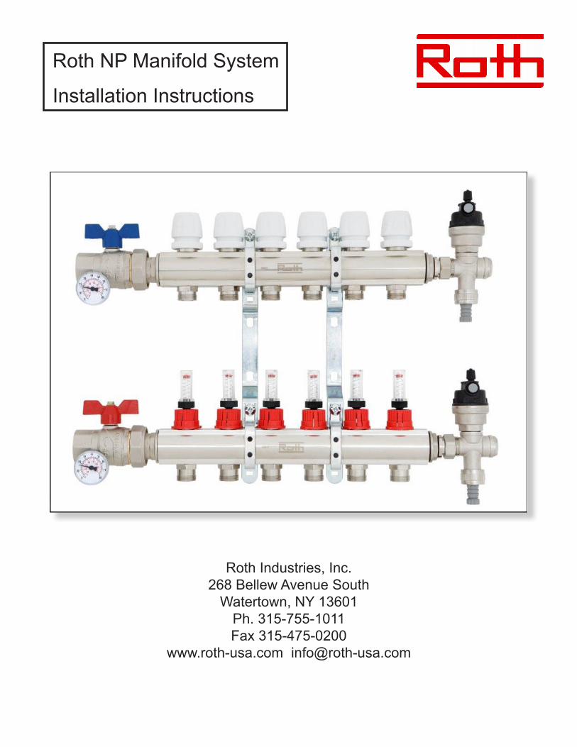
Roth NP Manifold System
Installation Instructions
Roth Industries, Inc. 268 Bellew Avenue South
Watertown, NY 13601Ph. 315-755-1011Fax 315-475-0200
www.roth-usa.com [email protected]

Roth NP Manifold System
Installation Instructions
Roth Industries, Inc. 315-755-1011 e-mail - [email protected] www.roth-america.com 2
1) Product description
• Constructed of heavy wall extruded nickel plated brass alloy. • Available in 1” and 1-1/4” trunk sizes.• 1” manifolds available in 2 - 12 loop connections.• 1-1/4” manifolds available in 4 - 12 loop connections.• Furnished complete with straight isolation ball valves for supply and return connections (1),
fill/drainvalvetees(2),automaticairvents(3),thermometersforsupplyandreturnconnections(4) and plated steel mounting brackets with rubber isolators (5).
• Flow meters (6) on the supply manifold feature a two stage adjustment capability via the main valveusedforshut-offandmacroflowadjustmentandtheflowmeterusedforfineadjustment.Flow rate scale – 0-1.6 gpm/0-6 lpm.
• Multi-turn manual shut-off valves (7) are included on the return manifold valve assemblies. The manual operators can be replaced with the Roth thermal valve actuator to allow for the installation and control of multiple zones from a single manifold.
• Supply/returnisolationballvalveassembliesandthedrain/fillandairventteescanbemountedoneitherendofthemanifoldsettoprovideinstallationandpipingflexibility.
• TheNPmanifoldusesUni-bloccompressionfittings(8)toattachlooptubing,theseareorderedand shipped separately from the manifold assembly.
1
1
2
2
7 3
3
4
455
6
2315031016 NP Manifold Uni-bloc Fitting 3/8”2315031017 NP Manifold Uni-bloc Fitting 1/2”2315031018 NP Manifold Uni-bloc Fitting 5/8”2315031019 NP Manifold Uni-bloc Fitting 3/4”
8
Roth NP Manifold System
Installation Instructions
Roth Industries, Inc. 315-755-1011 e-mail - [email protected] www.roth-america.com 3
Right-angle supply/return ball valve and temperature gauge assemblies
1” - 2315031028
1/4” - 2315031029
Manifold loop outlet cap 2315031037
Differential bypass valve assembly 2315031047
Thermal Actuators 2340055354
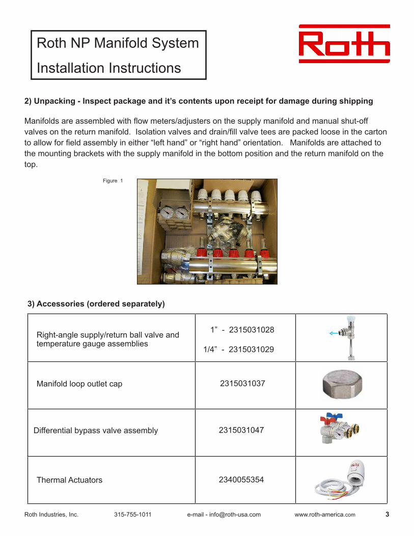
Figure 1
2) Unpacking - Inspect package and it’s contents upon receipt for damage during shipping
Manifoldsareassembledwithflowmeters/adjustersonthesupplymanifoldandmanualshut-offvalvesonthereturnmanifold.Isolationvalvesanddrain/fillvalveteesarepackedlooseinthecartontoallowforfieldassemblyineither“lefthand”or“righthand”orientation.Manifoldsareattachedtothe mounting brackets with the supply manifold in the bottom position and the return manifold on the top.
3) Accessories (ordered separately)
Roth NP Manifold System
Installation Instructions
Roth Industries, Inc. 315-755-1011 e-mail - [email protected] www.roth-america.com 4
5) Specifications
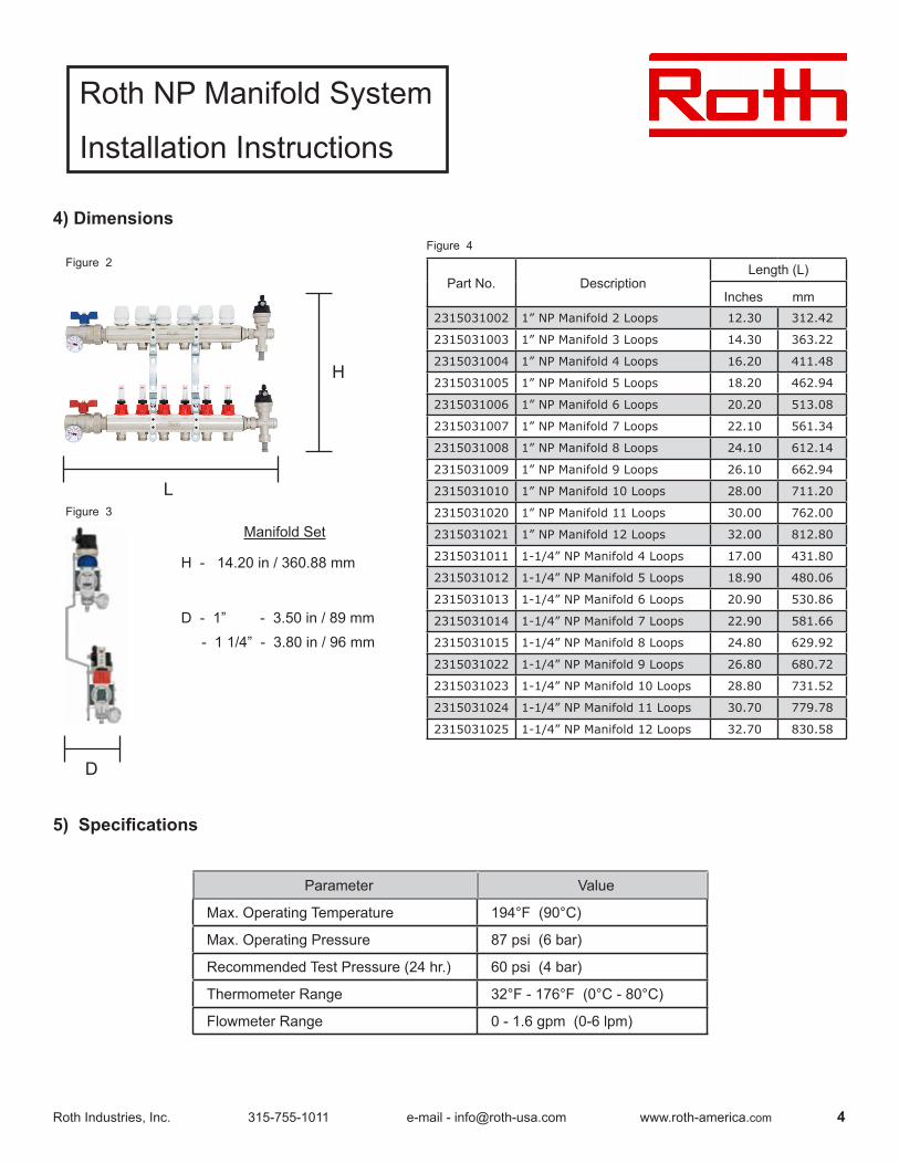
4) Dimensions
H
L
Manifold Set
H - 14.20 in / 360.88 mm
D - 1” - 3.50 in / 89 mm - 1 1/4” - 3.80 in / 96 mm
D
Part No. DescriptionLength (L)
Inches mm 2315031002 1” NP Manifold 2 Loops 12.30 312.42
2315031003 1” NP Manifold 3 Loops 14.30 363.22
2315031004 1” NP Manifold 4 Loops 16.20 411.48
2315031005 1” NP Manifold 5 Loops 18.20 462.94
2315031006 1” NP Manifold 6 Loops 20.20 513.08
2315031007 1” NP Manifold 7 Loops 22.10 561.34
2315031008 1” NP Manifold 8 Loops 24.10 612.14
2315031009 1” NP Manifold 9 Loops 26.10 662.94
2315031010 1” NP Manifold 10 Loops 28.00 711.20
2315031020 1” NP Manifold 11 Loops 30.00 762.00
2315031021 1” NP Manifold 12 Loops 32.00 812.80
2315031011 1-1/4” NP Manifold 4 Loops 17.00 431.80
2315031012 1-1/4” NP Manifold 5 Loops 18.90 480.06
2315031013 1-1/4” NP Manifold 6 Loops 20.90 530.86
2315031014 1-1/4” NP Manifold 7 Loops 22.90 581.66
2315031015 1-1/4” NP Manifold 8 Loops 24.80 629.92
2315031022 1-1/4” NP Manifold 9 Loops 26.80 680.72
2315031023 1-1/4” NP Manifold 10 Loops 28.80 731.52
2315031024 1-1/4” NP Manifold 11 Loops 30.70 779.78
2315031025 1-1/4” NP Manifold 12 Loops 32.70 830.58
Figure 2
Figure 3
Figure 4
Parameter Value
Max. Operating Temperature 194°F (90°C)
Max. Operating Pressure 87 psi (6 bar)
Recommended Test Pressure (24 hr.) 60 psi (4 bar)
Thermometer Range 32°F - 176°F (0°C - 80°C)
Flowmeter Range 0 - 1.6 gpm (0-6 lpm)
Roth NP Manifold System
Installation Instructions
Roth Industries, Inc. 315-755-1011 e-mail - [email protected] www.roth-america.com 5
6) Mounting
Warning: Flowmeters allow flow in one direction only. Supply piping must be attched to
manifold with flowmeters.
Location giuidelines1. The manifold system must be accessible for future inspection and maintenance.2. The supply/return and loop tubing should have an unobstructed approach and any bend radius must be large enough to prevent kinks. 3.Manifoldsystemlocationsshouldnotbeinfloodproneareasorexposedtotheelements.4. Avoid exposing tubing to direct sunlight, even through a door or window. Long term exposure to UV rays will cause the tubing to degrade.5. If manifold systems are located in an unconditioned space appropriate measures must be
taken to prevent damage from freezing.6. Manifolds must be horizontally or vertically level depending upon orientation.
Orientation The NP manifold can be mounted in any position, however the following conditions may occur when manifolds are mounted in positions other than upright (loop tubing approaching from bottom):1. Upside down position (loop tubing approaching from above)
a. Dirtmayaccumulateintheflowindicatorsovertime.Thiswillnothaveanyeffectontheflowratebutmaycauseflowindicatorstogivefalsereadingsorstopworkingaltogether.
b. Theflowindicatorslosesomeoftheirprecisioninthisorientationalthoughtheywillindicateflow.
c. Air vents must be inverted to operate as intended.2. Vertical position (loop tubing approaching from either side)
a. Dirtmayaccumulateintheflowindicatorswiththesameeffectsasabove.b. The automatic air vent will not operate. Turn plug in clockwise direction to close. Manual
airventmayusedduringfilingandpurging.
Caution: Conditions above do not qualify for warranty replacement.
HardwareThere are four mounting holes in the bracket set that will accommodate a 1/4”diameter fastener appropriate for the mounting surface material. These can includewood screws, sheet metal screws or through-bolting as required.
Roth NP Manifold System
Installation Instructions
Roth Industries, Inc. 315-755-1011 e-mail - [email protected] www.roth-america.com 6
7) Manifold pipe connections
Supply and Return Connections
The pipe connections on the attached straight ball valves are either 1” FPT (1” manifold) or 1-1/4” FPT (1-1/4” manifold). Use of a thread sealant compatible with water service is recommended.
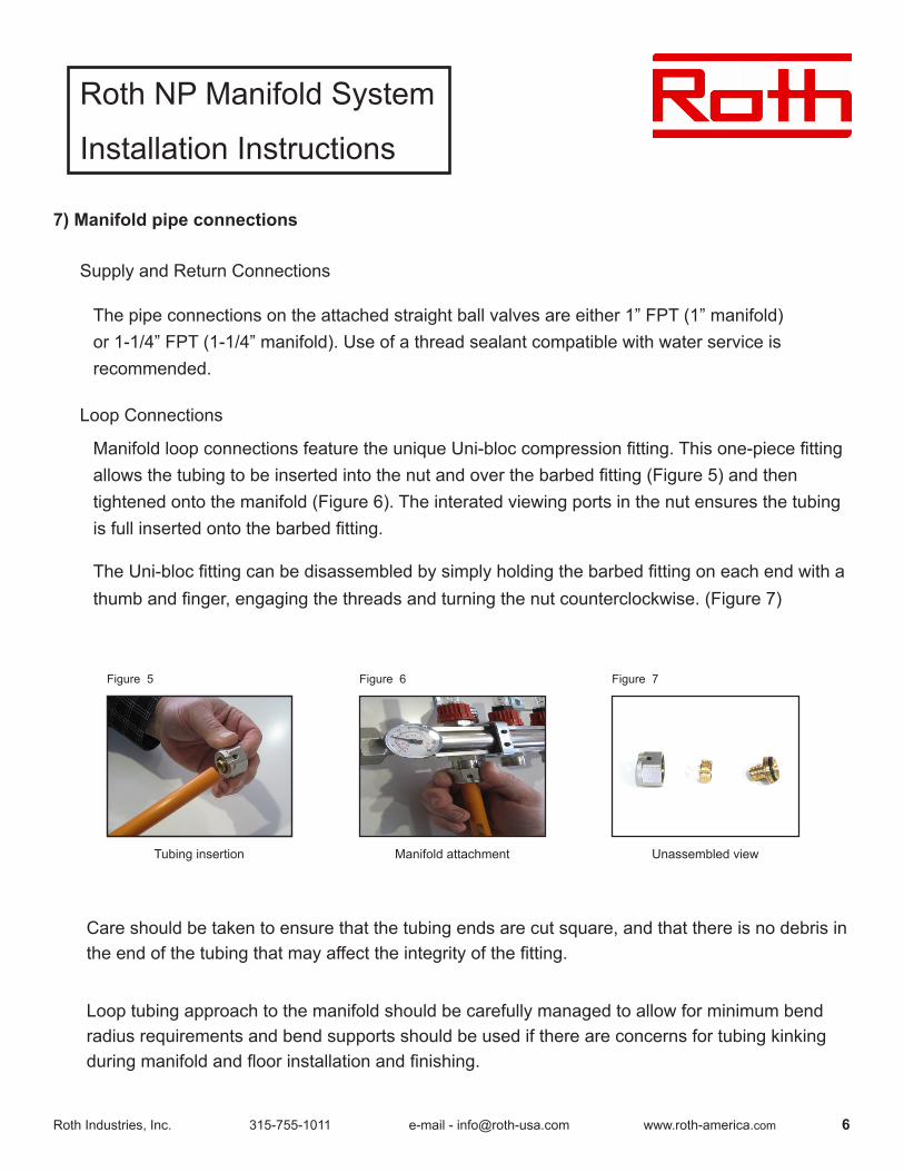
Loop Connections
ManifoldloopconnectionsfeaturetheuniqueUni-bloccompressionfitting.Thisone-piecefittingallowsthetubingtobeinsertedintothenutandoverthebarbedfitting(Figure5)andthentightened onto the manifold (Figure 6). The interated viewing ports in the nut ensures the tubing isfullinsertedontothebarbedfitting.
The Uni-bloc fittingcanbedisassembledbysimplyholdingthebarbedfittingoneachendwithathumbandfinger,engagingthethreadsandturningthenutcounterclockwise.(Figure7)
Care should be taken to ensure that the tubing ends are cut square, and that there is no debris in theendofthetubingthatmayaffecttheintegrityofthefitting.
Loop tubing approach to the manifold should be carefully managed to allow for minimum bend radius requirements and bend supports should be used if there are concerns for tubing kinking duringmanifoldandfloorinstallationandfinishing.
Figure 5
Tubing insertion Manifold attachment
Unassembled view
Unassembled view
Figure 6 Figure 7
Roth NP Manifold System
Installation Instructions
Roth Industries, Inc. 315-755-1011 e-mail - [email protected] www.roth-america.com 7
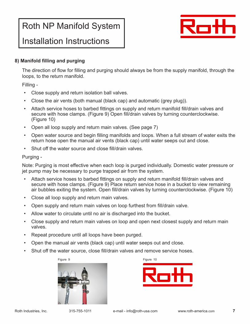
8) Manifold filling and purging
The direction offlowforfillingandpurgingshouldalwaysbefromthesupplymanifold,throughtheloops, to the return manifold.
Filling - • Close supply and return isolation ball valves.• Close the air vents (both manual (black cap) and automatic (grey plug)).• Attachservicehosestobarbedfittingsonsupplyandreturnmanifoldfill/drainvalvesand
securewithhoseclamps.(Figure9)Openfill/drainvalvesbyturningcounterclockwise.(Figure 10)
• Open all loop supply and return main valves. (See page 7)• Openwatersourceandbeginfillingmanifoldsandloops.Whenafullstreamofwaterexitsthe
return hose open the manual air vents (black cap) until water seeps out and close.• Shutoffthewatersourceandclosefill/drainvalves.
Purging -
Note: Purging is most effective when each loop is purged individually. Domestic water pressure or jet pump may be necessary to purge trapped air from the system.• Attachservicehosestobarbedfittingsonsupplyandreturnmanifoldfill/drainvalvesand
secure with hose clamps. (Figure 9) Place return service hose in a bucket to view remaining airbubblesexitingthesystem.Openfill/drainvalvesbyturningcounterclockwise.(Figure10)
• Close all loop supply and return main valves.• Opensupplyandreturnmainvalvesonloopfurthestfromfill/drainvalve.• Allow water to circulate until no air is discharged into the bucket. • Close supply and return main valves on loop and open next closest supply and return main
valves.• Repeat procedure until all loops have been purged.• Open the manual air vents (black cap) until water seeps out and close. • Shutoffthewatersource,closefill/drainvalvesandremoveservicehoses.
Figure 9 Figure 10

Roth NP Manifold System
Installation Instructions
Roth Industries, Inc. 315-755-1011 e-mail - [email protected] www.roth-america.com 8
1.6
1
.75
gpm
.5
.25
Figure 11
1.6
1
.75
gpm
.5
.25
Figure 12
1.6
1
.75
gpm
.5
.25
Figure 13
9) Loop flow adjustment
Eachloopsupplyconnectionisequippedwithavalve/flowmeterassembly.Themainvalveisinthemanifoldflowpathandisintheclosed position when the manifold is shipped.
Openingmainflowmetervalve (Figure 11)
• Pullredlockshieldintothe“UP” position
• Turn red lock shield counterclockwise until fully open. (flowmeterassemblywillalsoturn.)
Adjustingflow(Figure12)
• Pushredlockshieldin“DOWN”position.
• Turnflowmeterassemblycounterclockwisetoadjusttheflowrate.
Lockingflowmeterassembly(Figure13)
• Pullredlockshieldto“UP”positiontolockflowmeteradjustment.
Note: Main valve and flowmeter assembly must both be turned counterclockwise to achieve flow.
Equalizetheflowratesinallloopstomaintainevenheattransferthroughouttheheatedspace.
Roth NP Manifold System
Installation Instructions
Roth Industries, Inc. 315-755-1011 e-mail - [email protected] www.roth-america.com 9
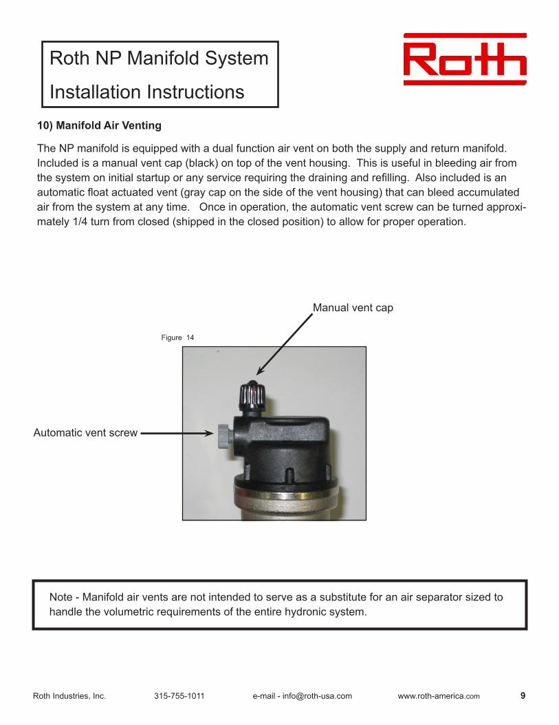
10) Manifold Air Venting
The NP manifold is equipped with a dual function air vent on both the supply and return manifold. Included is a manual vent cap (black) on top of the vent housing. This is useful in bleeding air from thesystemoninitialstartuporanyservicerequiringthedrainingandrefilling.Alsoincludedisanautomaticfloatactuatedvent(graycaponthesideoftheventhousing)thatcanbleedaccumulatedair from the system at any time. Once in operation, the automatic vent screw can be turned approxi-mately 1/4 turn from closed (shipped in the closed position) to allow for proper operation.
Note - Manifold air vents are not intended to serve as a substitute for an air separator sized to handle the volumetric requirements of the entire hydronic system.
Manual vent cap
Automatic vent screw
Figure 14