roth ma ris - rhea mprheamp.com/wp-content/uploads/2016/10/roth_hydraulics_ti... · selection of...
TRANSCRIPT

Hydraulics
excellent pressure solutions
Accumulators
Bladder Accumulators
Technical InformationSeries CE + ASME
2
Construction and Description General 3 Function 3 Overview of Roth bladder accumulators 4 Selection of pressure fluids 4 CE series BLAK / BLUAK 5
Acceptance Acceptance selection table 6
Type Code BLAK CE series BLAK 7
CE Series BLAK CE series BLAK 1 - 50 l 8
Type Code BLUAK ASME series BLUAK 9
ASME Series BLUAK ASME series BLUAK 1 QT to 15 Gal – 3000 psi and 4000 psi series 10 ASME series BLUAK 2.5 Gal to 15 Gal – 5000 psi and 6000 psi series 11
ASME Series BLUAK Top-Repairable ASME series BLUAK-T 2.5 Gal to 15 Gal – 3000 psi and 4000 psi series 12 ASME series BLUAK-T 2.5 Gal to 15 Gal – 5000 psi and 6000 psi series 13
Accumulator Calculation Form 14
Index
3
HydraulicsConstruction and Description
General
BOLENZ & SCHÄFER has been a leader in the area of accumu-lator technology for more than 60 years. As a specialist in hydrau-lic accumulator applications, it is our primary objective to develop efficient solutions in line with market needs. In accordance with the rebranding initiative of our parent company, Roth Industries – of which Bolenz & Schäfer has been a solid member for more than a quarter of a century – we are proud to continue our activities as Roth Hydraulics.
The Roth bladder accumulator enhances the product spectrum by a further innovative product. Cost optimised, low maintenance, practically wear resistant, durable, available in versions for special media and applications as well as suitable for use in extreme con-ditions – these are some of the product's distinguishing features. Roth hydraulic accumulators fulfil all applicable regulations and directives.
Accumulator adapters, safety and shut-off valve blocks along with other accessories can be found in our separate cata-logue Accumulator Accessories.
The application fields of the Roth bladder accumulator are many and diverse. Amongst other applications, they can be used for: > Energy storage> Pulsation damping> Volume compensation> Hydraulic springing> Shock absorption> Media transfer partition> Emergency operation
Function
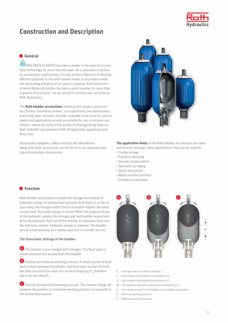
Roth bladder accumulators enable the storage and release of hydraulic energy. As pressurised hydraulic fluid flows in at the oil port valve, the nitrogen within the accumulator bladder becomes compressed. Hydraulic energy is stored. When the pressure drops in the hydraulic system, the nitrogen gas and bladder expand and drive the hydraulic fluid out of the bladder accumulator back into the hydraulic system. Hydraulic energy is released. The bladder serves simultaneously as a media separator or transfer barrier.
The three basic settings of the bladder:
A The bladder is pre-charged with nitrogen. The fluid valve is closed and prevents escape from the bladder.
B Position at minimum working pressure. A small volume of fluid must remain between the bladder and fluid valve so that the blad-der does not close the valve disc at each emptying. P0 therefore has to be less than P1.
C Position at maximum working pressure. The volume change ΔV between the position at minimum working position corresponds to the stored fluid volume.
V0 = Total gas volume of the accumulator
V1 = Gas volume in the bladder accumulator at P1
V2 = Gas volume in the bladder accumulator at P2
ΔV = Dissipated or absorbed useful volume between P1 / P2
P0 = Pre-charge pressure of the bladder in the bladder accumulator
P1 = Minimum working pressure
P2 = Maximum working pressure
A B C
P0
V0
P1
V1
P2
V2
ΔV
4
Overview of Roth bladder accumulators
Volume 1 ... 57 l
Transport filling approx. 1 bar
Operating pressure max. 350 bar (420 bar)
Materials Steel, special materials, stainless steel (on request)
Media HFC, HLP, HFD ...
Temperature -40 ... +80°C
Volume flow (Qmax.) max. 1000 l/min
Installation position preferably vertical to ... horizontal
Accumulator shell sand blasted
primer coated
top coat/ special coating available
Oil/ Gas valve Carbon steel
Stainless steel, nickel
Fluid ports G inside thread G1/2 - G2 SAE thread connections
Flange connections available
Special connections available
Bladder (elastomers) NBR, TT-NBR, ECO, IIR, FKM, EPDM
Acceptances DGR 2014/68/EU, ASME, ML China, NR13, EAC, GL, ABS, BV, DNV, Canada, CCS, LRS, RINA
Construction and Description
Gas fillingOnly nitrogen of Class 4 is to be used, never oxygen or compressed air.
Design pressure (see selection table)The design pressure corresponds to the maximum permissible operating pressure (PS) and is the maximum setting pressure of safety equipment against excess pressure (safety valves, burst discs) at the same time. We recommend operating the accumulators with a maximum pres-sure of 0.9 x PS to prevent safety equipment from responding.
Accumulator installationTo prevent damage to the bladder, a vertical accumulator assem-bly, with fluid connection below, is preferable. If the assembly site requires a horizontal mounting, the inside of the accumulator shell must be provided with the plastic coating specially developed by Roth Hydraulics. This special coating minimises abrasive wear between the accumulator inside wall and bladder.
Selection of pressure fluids
Overview of Roth bladder accumulators
Operating temperatureTemperature range standard: -15° C to +80° C, different tempera-ture ranges, e.g. -40° C to +80° C, available on request.
Condition on deliveryAccumulator shell base-coated with universal priming colour RAL 5015, manufactured seamless, inside sand-blasted. Colour treatment and blasting or other surface coatings (e.g. galvanic zinc plating) are possible. Please contact us for other solutions.
Pressure fluidsFluids of Group 2 according to DGR 2014/68/EU and nitrogen, or in relation to bladder elastomer and temperature range, according to data in the "Pressure fluids" table below. The oil purity class must be min. 19/17/14 (NAS 1638-KJ8) according to ISO 4406.
Gas pre-charge pressureTo prevent the oil valve from closing at each oil extraction, the gas pre-charge pressure should not be higher than 0.9 x the maximum working pressure (P1) and not lower than 0.25 x the maximum working pressure (P2).
Fluid Temperature range °C Elastomer
... especially for low temperature range* -32 ... +115 Hydrin C (ECO)
Fluids based on mineral oil* -15 ... +100 NBR
-28 ... +80 TT-NBR
HFA, HFB* +5 ... +55 NBR
HFC* -15 ... +60 NBR
Fluids based on phosphate ester and some synthetic fluids* -15 ... +120 Butyl (IIR)
Fluids based on phosphate ester* -40 ... +120 Ethylene propylene diene (EPDM)
Hardly flammable and / or synthetic fluids* -20 ... +140 Viton (FKM)
*Fluid selections for low temperature ranges as well as for temperature applications below -20°C or above +80°C require consultation.
G Note Operation and Maintenance Please observe the information in the operating and maintenance instructions for this.

5
HydraulicsConstruction and Description
CE Series BLAK / ASME Series BLUAK
4
3
12
7
1011
5
1
2
8/9
6
Item Designation Material
1 Accumulator shell Carbon steel
2 Elastomer bladder NBR
3 Lock nut Carbon steel
4 Gas-side valve Stainless steel
5 Protection cap PA6
6 Oil-side valve Carbon steel, pipe thread ISO 228
7 Separated ring Carbon steel / Elastomer
Item Designation Material
8 O-ring NBR / FKM
9 Back-up ring PTFE
10 Spacer ring Carbon steel
11 Slotted nut = Threaded ring Carbon steel
12 Type plate Aluminium
13 Adapter Carbon steel
Standard BLAK / BLUAK Special version BLUAK Top-Repairable
13

6
Acceptance
Acceptance
Acceptance selection table
Roth hydraulic accumulators are manufactured and approved for the European market in accordance with the "Pressure Equipment Directive". Hydraulic accumulators according to Pressure Equipment Direc-tive >1 L volume are provided with a CE mark and are supplied with a declaration of conformity and a corresponding operating manual. The Pressure Equipment Directive is also accepted by many other countries besides the EU member states. Only some additional approval documentation may be required. Countries such as Russia or China also require an approval, which Roth Hydraulics has. Pressure vessel shipment to the USA must correspond to the American regulations, the ASME Code. Roth Hydraulics has been approved since 1981, according to ASME Code Section VIII Divi-sion 1; and has the longest experience with these regulations in Germany as a hydraulic accumulator manufacturer. Vessels with ASME acceptance are marked with the so-called "U-stamp" and supplied with a data report as acceptance documentation.The scope of the ASME Code only covers pressure vessels and accumulators with an internal diameter greater than 6 inches.
The CE series BLAK can therefore be used for accumulator diame-ters less than 6 inches.Vessels according to the ASME Code are also accepted in Canada. In Canada, an additional approval (Canadian Registration Number, CRN) is required for the relevant Destination province. The prov-ince or installation site must be indicated along with the order. Maritime applications form part of daily business at Roth Hydrau-lics and are hence routine procedures. A selection of the potential maritime acceptances can be found in the following table.
Roth Hydraulics has all important product and company approvals worldwide. The following tables contain a selection of the most common acceptance variants. If your planned installation country or the required acceptance is not listed, please indicate this in plain text along with the enquiry.
Country code Countries Approval regulation Var. no.
EU EU member states Pressure Equipment Directive 2014/68/EU with CE mark 50
RUS Russia Pressure Equipment Directive 2014/68/EU + EAC 520
VRC China Pressure Equipment Directive 2014/68/EU + ML (> 30 L) 534
BR Brazil Pressure Equipment Directive 2014/68/EU + CE mark + NR 13 (Brazil) 515
USA USA ASME Code Sect. VIII Div. 1 15
Country code Countries Approval regulation Var. no.
CCS Various countries China Classification Society 537
ABS Various countries American Bureau of Shipping 510
LRS Various countries Lloyd's Register of Shipment 5
GL Various countries Germanischer Lloyd 41
RINA Various countries RINA 536
BV Various countries Bureau Veritas 506
DNV Various countries Det Norske Veritas 509
Country code Countries Approval regulation Var. no.
CND Canada ASME Code + CRN (Canadian Registration No.) Approval depending on province – indicate province 29
ASME DOSH Malaysia ASME + DOSH Malaysia 61
Standard acceptances:
Maritime acceptance:
Special acceptances:

7
Hydraulics
Series BL.. – HF– …– …– …–
▴ ▴ ▴ ▴ ▴ BLAK High- Oil content max. operating Outside ø TYPE Flow [l] pressure [bar] [cm]
Material/ Coating
...– ◀
C = (Standard) carbon steel
N = Nickel plated
X = Stainless steel on request
V = (Special coating) carbon steel
A = Special material on request
K = *inside plastic coated
Bladder material
...– ◀
1 = (Standard) NBR
2 = (Hydrin) ECO
3 = (Low temperature) TT-NBR
4 = (Butyl) IIR on request
5 = (Viton) FKM
6 = (Ethylene propylene diene) EPDM on request
Oil connection
...– ◀
G =(Standard) pipe thread
(without adapter) ISO 228
R = Pipe thread (with adapter) ISO 228
L = Flange connection, SAE 3000
H = Flange connection, SAE 6000
M = Metric thread
T = NPT
S = Special thread (please also indicate in plain text)
Acceptance
...– ◀50 = (Standard) Pressure Equipment Directive
2014/68/EU
… = Others see: Acceptance selection table
Material of oil valve
...– ◀
C = (Standard) carbon steel
P = Carbon steel zinc plated
N = Carbon steel nickel plated
X = Stainless steel
Material of gas valve ...– ◀
X = (Standard) stainless steel
A = Special material (please also indicate in plain text)
P0 pre-charge pressure ... ◀ … = Filling according to customer request [bar]
Type Code BLAK
CE Series BLAK
Example: BLAK 50 - 330 - 22 - C+K -1- G - 50 - X - X - 30
Product for order designation is:
Type: BLAK
Oil content: 50 litre
Pressure: 330 bar
Outside ø: 22 cm
Material/Coating: Carbon steel + inside plastic coated
Bladder material: Standard (NBR)
Oil connection: G2
Acceptance: Pressure Equipment Directive
Material of oil valve: Stainless steel
Material of gas valve: Stainless steel
Pre-charge pressure as required by customer 30 bar
Order designation
G Note: The use of the type code generally ensures our ability to supply. Diverse bladder accumulators with order numbers are listed on the following pages. These are only valid for the types described there. Please observe the corresponding specification!
* inside In the case of a plastic coated inside surface, please indicate "+K" in the order code (see example box "C+K").
Please indicate the required thread size/connection nominal width along with this selection.

8
CE Series BLAK
Gas volume Design pressure Type/Order number
Note
Tem
pera
ture
ra
nge Weight Dimensions
[l] [bar] [Kg] G 1ø D A1 A2 ø B1 ø B2 Q
[mm] [l/s]
1 350BLAK 01-350-11,4
4204019650
Onl
y fo
r BLA
K ...
-...-C
-1-G
-50
-C-X
-15
... +
80°C
6 G1 1/4 114 338 202 53 35 7.5
2.5 350BLAK 02.5-350-11,4
4204019639 10 G1 1/4 114 547 411 53 35 7.5
4 350BLAK 04-350-16,8
4204019420 13 G1 1/4 168 421 287 53 35 7.5
5 350BLAK 05-350-11,4
4204019638 16 G1 1/4 114 896 760 53 35 7.5
6 350BLAK 06-350-16,8
4204019419 19 G1 1/4 168 551 416 53 35 7.5
10 330BLAK 10-330-22
4204018514 30 G2 220 574 402 76 35 15
20 330BLAK 20-330-22
4204018513 45 G2 220 884 712 76 35 15
24.5 330BLAK 24.5-330-22
4204018512 54 G2 220 1019 847 76 35 15
32 330BLAK 32-330-22
4204018511 80 G2 220 1404 1232 76 35 15
42 330BLAK 42-330-22
4204018510 94 G2 220 1544 1372 76 35 15
50 330BLAK 50-330-22
4204018509 108 G2 220 1919 1747 76 35 15
A1
øB2
GøD
A2
øB1
7/8"
14U
NF
G Note: The dimensions may vary slightly depending on the materials used and/or applied acceptances. In the event of an order, you will receive a binding drawing for approval for non-standard products.
CE Series BLAK 1 - 50 l

9
Hydraulics
Series BL.. – T– HF …– …– …–
▴ ▴ ▴ ▴ ▴ ▴ BLUAK Top- High- Oil max. Outside ø TYPE Repair- flow content Operating [cm] able [gal] pressure [psi]
Material/ Coating
...– ◀
C = (Standard) carbon steel
N = Nickel plated
X = Stainless steel on request
V = (Special coating) carbon steel
A = Special material on request
K = *inside plastic coated
Bladder material
...– ◀
1 = (Standard) NBR
2 = (Hydrin) ECO
3 = (Low temperature) TT-NBR
4 = (Butyl) IIR on request
5 = (Viton) FKM
6 = (Ethylene propylene diene) EPDM on request
Oil connection
...– ◀
B =(Standard) SAE
(without adapter)
R = Pipe thread (with adapter) ISO 228
L = Flange connection, SAE 3000
H = Flange connection, SAE 6000
M = Metric thread
T = NPT
S = Special thread (please also indicate in plain text)
G = Pipe thread (without adapter) ISO 228
Acceptance...– ◀
15 = ASME Code Section VIII Division I
… = Others see: Acceptance selection table
Materialoil valve
...– ◀
C = (Standard) carbon steel
P = Carbon steel zinc plated
N = Carbon steel nickel plated
X = Stainless steel
MaterialGas valve ...– ◀
X = (Standard) stainless steel
A = Special material (please also indicate in plain text)
Gas connection...– ◀
E1 = Standard 7/8"-14 UNF-1A
E2 = Special version on request
P0 pre-charge pressure ... ◀ … = Filling according to customer indication [psi]
Type Code BLUAK
ASME Series BLUAK / BLUAK Top-Repairable
Example: BLUAK 5 - 5000 - 24,5 - C -1- G - 15 - C - X - E1 - 30
Product for order designation is:
Type: BLUAK
Oil content: 5 gallons
Pressure: 5000 psi
Outside ø: 24.5 cm
Material/Coating: Carbon steel
Bladder material: Standard (NBR)
Oil connection: G2
Acceptance: ASME
Material of oil valve: Carbon steel
Material of gas valve: Stainless steel
Gas connection: Standard 7/8"
Pre-charge pressure as required by customer 30 psi
Order designation
G Note: The use of the type code generally ensures our ability to supply. Diverse bladder accumulators with order numbers are listed on the following pages. These are only valid for the types described there. Please observe the corresponding specification!
* inside In the case of a plastic coated inside surface, please indicate "+K" in the order code (see example box "C+K").
Please indicate the required thread size/connection nominal width along with this selection.

10
ASME Series BLUAK
Gas volume Design pressure Type/Order number
Note
Tem
pera
ture
ra
nge Weight Dimensions
[gal] / [l] [psi] / [bar] [Kg] / [lbs] Bø D A1 A2 ø B1 ø B2 Q
[mm] / [inch] [l/s] / [gpm]
1QT1
3000207
BLUAK 1QT-3000-11.4 4204028560
Onl
y fo
r BLU
AK ..
.-C-1
-B-1
5-C-
X-E1
-4 ..
. +20
0°
F /
-15
… +
80°
C
715.4
1 5/16"- 12
1144.49"
30912.17"
1907.5"
421.65"
351.4"
5794000
276BLUAK 1QT-4000-11.4
4204030119
14
3000207
BLUAK 01-3000-16.8 4204028561 16
35.31 5/8"-
12168
6.61"427
16.81"286
11.26"58
2.28"35
1.4"7.51194000
276BLUAK 01-4000-16.8
4204030165
2.510
3000207
BLUAK 2.5-3000-22.94204028474 38
83.81 7/8"-
12229
9.01"572
22.52"397
15.63"763"
351.4"
152384000
276BLUAK 2.5-4000-22.9
4204030166
520
3000207
BLUAK 5-3000-22.94204028475 61
134.51 7/8"-
12229
9.01"884
34.80"709
27.91"763"
351.4"
152384000
276BLUAK 5-4000-22.9
4204030167
1032
3000207
BLUAK 10-3000-22.94204028476 101
222.71 7/8"-
12229
9.01"1420
55.91"1245
49.02"763"
351.4"
152384000
276BLUAK 10-4000-22.9
4204030168
1557
3000207
BLUAK 15-3000-22.94204028477 146
321.91 7/8"-
12229
9.01"2005
78.94"1830
72.03"763"
351.4"
152384000
276BLUAK 15-4000-22,9
4204030169
G Note: The dimensions may vary slightly depending on the materials used and/or applied acceptances. In the event of an order, you will receive a binding drawing for approval for non-standard products.
ASME series BLUAK 1QT to 15 Gal – 3000 psi and 4000 psi series
A1
øB2
BøD
A2
øB1
7/8"
14U
NF

11
HydraulicsASME Series BLUAK
Gas volume Design pressure Type/Order number
Note
Tem
pera
ture
ra
nge Weight Dimensions
[gal] / [l] [psi] / [bar] [Kg] / [lbs] Bø D A1 A2 ø B1 ø B2 Q
[mm] / [inch] [l/s] / [gpm]
2.510
5000345
BLUAK 2.5-5000-24,54204028482
Onl
y fo
r BL
UAK
...-C
-1-B
-15-
C-X-
E1
-4 ..
. +20
0°
F /
-15
… +
80°
C
58127.9
1 7/8"-12
2459.65"
58122.87"
41316.26"
763"
351.4"
152386000
414BLUAK 2.5-6000-24.5
4204030170
520
5000345
BLUAK 5-5000-24.54204028503
95209.4
1 7/8"-12
2459.65"
88634.88"
71828.27"
763"
351.4"
152386000
414BLUAK 5-6000-24.5
4204030171
1032
5000345
BLUAK 10-5000-24.54204028484
161354.9
1 7/8"-12
2459.65"
141355.63"
124548.02"
763"
351.4"
152386000
414BLUAK 10-6000-24.5
4204030172
1557
5000345
BLUAK 15-5000-24.54204028485
234545.9
1 7/8"-12
2459.65"
199778.62"
182972.01"
763"
351.4"
152386000
414BLUAK 15-6000-24.5
4204030173
G Note: The dimensions may vary slightly depending on the materials used and/or applied acceptances. In the event of an order, you will receive a binding drawing for approval for non-standard products.
ASME series BLUAK 2.5 Gal to 15 Gal – 5000 psi and 6000 psi series
A1
øB2
BøD
A2
øB1
7/8"
14U
NF

12
ASME Series BLUAK Top-Repairable
Gas volume Design pressure Type/Order number
Note
Tem
pera
ture
ra
nge Weight Dimensions
[gal] / [l] [psi] / [bar] [Kg] / [lbs] Bø D A1 A2 ø B1 ø B2 Q
[mm] / [inch] [l/s] / [gpm]
2.510
3000207
BLUAK-T-2.5-3000-22.94204028493
Onl
y fo
r BL
UAK
...-C
-1-B
-15-
C-X-
E1
-4 ..
. +20
0°
F /
-15
… +
80°
C
4088.2
1 7/8"-12
2299.01"
54721.54"
39415.51"
763"
351.4"
152384000
276BLUAK-T-2.5-4000-22.9
4204030174
520
3000207
BLUAK-T-5-3000-22,94204028494 63
138.91 7/8"-
12229
9.01"852
33.54"699
27.52"763"
351.4"
152384000
276BLUAK-T-5-4000-22.9
4204030175
1032
3000207
BLUAK-T-10-3000-22.94204028495 102
224.91 7/8"-
12229
9.01"1378
54.25"1225
48.23"763"
351.4"
152384000
276BLUAK-T-10-4000-22.9
4204030176
1557
3000207
BLUAK-T-15-3000-22.94204028496 148
326.31 7/8"-
12229
9.01"1981
77.89"1825
71.92"763"
351.4"
152384000
276BLUAK-T-15-4000-22.9
4204030177
G Note: The dimensions may vary slightly depending on the materials used and/or applied acceptances. In the event of an order, you will receive a binding drawing for approval for non-standard products.
ASME series BLUAK-T – 2.5 Gal to 15 Gal – 3000 psi and 4000 psi series
A1
øB2
BøD
A2
øB1
7/8"
14U
NF

13
HydraulicsASME Series BLUAK Top-Repairable
Gas volume Design pressure Type/Order number
Note
Tem
pera
ture
ra
nge Weight Dimensions
[gal] / [l] [psi] / [bar] [Kg] / [lbs] Bø D A1 A2 ø B1 ø B2 Q
[mm] / [inch] [l/s] / [gpm]
2.510
5000345
BLUAK-T-2.5-5000-24.54204028502
Onl
y fo
r BL
UAK
...-C
-1-B
-15-
C-X-
E1
-4 ..
. +20
0°
F /
-15
… +
80°
C
60132.3
1 7/8"-12
2459.65"
56322.17"
41316.26"
763"
351.4"
152386000
414BLUAK-T-2.5-6000-24.5
4204030178
520
5000345
BLUAK-T-5-5000-24.54204028503 94
207.31 7/8"-
12245
9.65"868
34.17"718
27.27"763"
351.4"
152386000
414BLUAK-T-5-6000-24.5
4204030179
1032
5000345
BLUAK-T-10-5000-24.54204028504 151
332.91 7/8"-
12245
9.65"1395
54.92"1245
49.02"763"
351.4"
152386000
414BLUAK-T-10-6000-24.5
4204030180
1557
5000345
BLUAK-T-15-5000-24.54204028506 215
4741 7/8"-
12245
9.65"1979
77.91"1828
72.01"763"
351.4"
152386000
414BLUAK-T-15-6000-24.5
4204030181
G Note: The dimensions may vary slightly depending on the materials used and/or applied acceptances. In the event of an order, you will receive a binding drawing for approval for non-standard products.
ASME series BLUAK-T – 2.5 Gal to 15 Gal – 5000 psi and 6000 psi series
A1
øB2
BøD
A2
øB1
7/8"
14U
NF

14
Calculation
Accumulator Calculation Form
Accumulator calculation
Working pressure [bar] minimum
maximum
Discharge volume [l]
Discharge time [s]
alternatively to discharge volume and discharge time, total volume of accumulator [l]
Ambient temperature [°C] minimum
maximum
Medium temperature [°C] minimum
maximum
Medium Fluid side
Gas side
Material Bladder
Accumulator
Load alternation per week Number
Operating mode Number of work shifts
Acceptance Installation country
Regulations
Date Company Name
Description of application:
Fax: +49 (0) 64 61 / 9 33-161 Email: [email protected]
Fax: +86 (0) 5 12 / 53 20 88 39 Email: [email protected]
Fax: +1 (0) 3 15 / 4 75 02 00Email: [email protected]

15
HydraulicsOur strengths Your benefits
Innovative
> Own product development> In-house technology centre for all
relevant tests and inspections including: Burst and swell test bench,
endurance test rig, cold chamber, salt spray test
> Close collaboration with universities and institutes
> Tested and proven design and simula-tion program for all types of hydraulic accumulator
Complete product portfolio
> Extensive range of diaphragm, blad-der and piston accumulators
> Complete and tested accessories range, including for professional installation and for (accumulator) safety
> Accumulator measuring and monitor-ing systems, mechanical or non-con-tact
> Customised special solutions
Global
> Worldwide production, assembly and service sites
> Certified according to DIN EN ISO 9001:2015, DIN EN ISO 14001
> Proximity to customers thanks to own representatives and extensive dealer network worldwide
> International production approvals, including ASME U-Stamp, Russian Customs Union, Korea KGS
15
Hydraulics

Hydraulics
Subj
ect t
o te
chni
cal m
odifi
cati
ons
420
4031
066
80
816
W3
Accumulators> Diaphragm accumulators> Bladder accumulators> Piston accumulators
Accumulator systems> Accumulator units> Monitoring systems> System accessories> Pressure vessels
Special solutions> Spring accumulators> Damper systems> Rail hydraulics> Special accumulators
Roth Hydraulics
ROTH Hydraulics GmbH (formerly Bolenz & Schäfer GmbH)Lahnstraße 34D-35216 Biedenkopf-Eckelshausen GermanyPhone: +49 (0) 64 61 / 9 33-0 Fax: +49 (0) 64 61 / 9 33-161 Email: [email protected]
ROTH Hydraulics (Taicang) Co., Ltd.(formerly BSD Hydraulic Technology (Taicang) Co., Ltd.)Building 14 A, No. 111, Dongting North Road, Taicang City,Jiangsu Province 215400, P.R. China Phone: +86 (0) 5 12 / 53 20 88 36 Fax: +86 (0) 5 12 / 53 20 88 39 Email: [email protected]
ROTH Hydraulics NA Inc.One General Motors Drive, PO Box 245, SyracuseNew York 13211USA Phone: +1 (0) 3 15 / 4 75 01 00Fax: +1 (0) 3 15 / 4 75 02 00Email: [email protected]