rotator - stuart equipment | hotplates3).pdf · instrucciones de funcionamiento...
TRANSCRIPT

Version 2.0
RotatorSTR4
Instructions for useManuel d'utilisationIstruzioni per l’usoInstrucciones de funcionamientoBedienungsanweisung

English
Support column
Drive unit
Drum fixing
Z control
Mains On/Off
Speedcontrol
Timer
RotatorSTR4Instructions for use
IntroductionThank you for purchasing this piece of Stuart equipment. To get the best performance from the equipment and for your own safety, please read these instructions carefully before use. Before discarding the packaging check that all parts are present and correct.
This equipment is designed to operate under the following conditions:
For indoor use onlyUse in a well ventilated areaAmbient temperature range +5ºC to +40ºCAltitude to 2000mRelative humidity not exceeding 80%Mains supply fluctuation not exceeding 10%Over-voltage category II IEC60364-4-443Pollution degree 2
If the equipment is not used in the manner described in this manual and with accessories other than those recommended by Stuart, the protection provided may be impaired.
Fig. 1: STR4 Drive unit

1
Electrical Installation
THIS EQUIPMENT MUST BE EARTHED
Before connection please ensure that the line supply corresponds to that shown on the rating plate.
Model Supply requirements Power
STR4 230V, 50Hz 50W
The STR4 is supplied with two mains leads fitted with IEC plugs for connection to the instrument. One has a U.K. 3 pin plug and the other has a 2 pin “Shuko” plug for connection to the mains. Choose the lead appropriate for your electrical installation and discard the other. Should neither lead be suitable, take the lead with the U.K. plug and replace the plug with a suitable alternative. This involves cutting off the moulded plug, preparing the cable and connecting to the re-wireable plug in accordance with its instructions.
THIS OPERATION SHOULD ONLY BE UNDERTAKEN BY A QUALIFIED ELECTRICIAN
NOTE: Refer to the equipment’s rating plate to ensure that the plug and fusing are suitable for the voltage and wattage stated.
The wires in the mains cable are coloured as follows:
BROWN - LIVEBLUE - NEUTRALGREEN/YELLOW - EARTH
The instrument is fitted with an IEC socket at the rear for connection of the mains lead. The appropriate mains lead should be connected BEFORE connection to the mains supply.
Should the mains lead need replacement, a cable of 1mm2 of harmonised code H05W-F connected to an IEC320 plug should be used.
IF IN DOUBT CONSULT A QUALIFIED ELECTRICIAN
Safety Advice Before Use
The unit should be carried using two hands.Never move or carry the unit while it is in use
or connected to the mains supply.
General DescriptionThe STR4 is a drive unit with variable speed control that can be set between 6 and 60rpm. For added convenience it also has an analogue timer that can be set from 10 to 60 minutes. Alternatively the unit can be set for continuous operation. The STR4 accepts one of five accessory drums that are designed to give different mixing actions.
OperationRefer to Fig. 1 to identify the parts and controls.
1. Assemble the drive unit and support column. Push the threaded ends of the two connecting rods through the holes in the support column and locate them into the corresponding two holes in the drive unit. Screw each connecting rod firmly into the drive unit.
2. Place the apparatus on a firm, level surface.
3. Attach the left hand fixing of the drum to the drum fixing on the drive unit.
4. Adjust the lateral position of the support column so that it is at the correct distance to accommodate the length of the drum shaft and secure in place with the thumb screw at the back.
5. Switch the mains On/Off and motor On/Off switches to On.
6. Turn the speed control knob until the desired rotation is seen.
7. For continuous operation, set the timer knob to Manual.
8. In order to mix for a given time, set the timer knob to the required time in minutes. When the set time is over, the unit will stop the rotation.
2
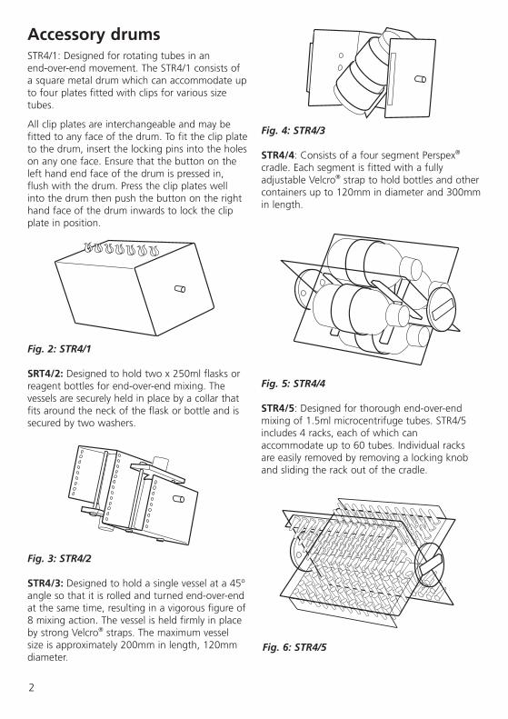
Accessory drumsSTR4/1: Designed for rotating tubes in an end-over-end movement. The STR4/1 consists of a square metal drum which can accommodate up to four plates fitted with clips for various size tubes.
All clip plates are interchangeable and may be fitted to any face of the drum. To fit the clip plate to the drum, insert the locking pins into the holes on any one face. Ensure that the button on the left hand end face of the drum is pressed in, flush with the drum. Press the clip plates well into the drum then push the button on the right hand face of the drum inwards to lock the clip plate in position.
Fig. 2: STR4/1
SRT4/2: Designed to hold two x 250ml flasks or reagent bottles for end-over-end mixing. The vessels are securely held in place by a collar that fits around the neck of the flask or bottle and is secured by two washers.
Fig. 3: STR4/2
STR4/3: Designed to hold a single vessel at a 45º angle so that it is rolled and turned end-over-end at the same time, resulting in a vigorous figure of 8 mixing action. The vessel is held firmly in place by strong Velcro® straps. The maximum vessel size is approximately 200mm in length, 120mm diameter.
Fig. 4: STR4/3
STR4/4: Consists of a four segment Perspex® cradle. Each segment is fitted with a fully adjustable Velcro® strap to hold bottles and other containers up to 120mm in diameter and 300mm in length.
Fig. 5: STR4/4
STR4/5: Designed for thorough end-over-end mixing of 1.5ml microcentrifuge tubes. STR4/5 includes 4 racks, each of which can accommodate up to 60 tubes. Individual racks are easily removed by removing a locking knob and sliding the rack out of the cradle.
Fig. 6: STR4/5

3
Maintenance & ServicingWARNING: Ensure the unit is disconnected from the mains electricity supply before attempting maintenance or servicing.
Periodically clean the instrument using a damp cloth and mild detergent solution. Do not use harsh or abrasive cleaning agents.
Any repairs or replacement of parts MUST be undertaken by suitably qualified personnel.
For a comprehensive list of parts required by service engineers conducting internal repairs, please contact the Service Department, quoting both the model number and serial number:
E-mail: [email protected]: +44 (0)1785 810475 Fax: +44 (0)1785 810471
Only spare parts supplied or specified by Stuart or its agents should be used. Fitting of non-approved parts may affect the performance of the safety features designed into the instrument. If in any doubt, please contact the Service Department of Bibby Scientific Ltd. or the point of sale.
For any other technical enquiries, please contact the Technical Support Department:E-mail: [email protected] Tel: +44 (0)1785 810433.
Spares and AccessoriesDescription Catalogue Number
Drum to hold test tube clip plates STR4/1
Clip plates for 12 x 12mm tubes (pair) STR1/1
Clip plates for 10 x 16mm tubes (pair) STR1/2
Clip plates for 8 x 19mm tubes (pair) STR1/3
Clip plates for 7 x 24mm tubes (pair) STR1/4
Drum with two platforms to hold flasks or bottles STR4/2
Drum with figure of 8 mixing action STR4/3
Drum with four segment cradle for bottles STR4/4
Drum with four segment cradle for microfuge tubes STR4/5
Spare rack for 60 x 1.5ml microfuge tubes SW2/1
WarrantyStuart warrants this equipment to be free from defects in material and workmanship, when used under normal laboratory conditions, for a period of three (3) years. In the event of a justified claim, Stuart will replace any defective component or replace the unit free of charge. This warranty does NOT apply if damage is caused by fire, accident, misuse, neglect, incorrect adjustment or repair, damage caused by installation, adaptation, modification, fitting of non-approved parts or repair by unauthorised personnel.
Bibby Scientific Ltd.Beacon Road, Stone, Staffordshire ST15 0SAUnited KingdomTel: +44 (0)1785 812121Fax: +44 (0)1785 813748E-mail: [email protected]

Technical Specification
STR4
Rotation speed 6 to 60rpm
Timer 10 to 60 minutes or continuous
Maximum load 3kg
Power 230V, 50/60Hz
Dimensions (w x d x h) mm 650 x 250 x 250mm
Net weight 6.4kg
Electrical supply 230V, 50Hz, 50W
4

These products meet the relevant EC harmonised standards for radio frequency interference and may be expected not to
interfere with, or be affected by, other equipment with similar qualifications. We cannot be sure that other equipment used in their vicinity will meet these
standards and we cannot guarantee that interference will not occur in practice. Where there is a possibility that injury, damage or loss might occur if equipment malfunctions due to radio frequency interference, or for general advice before use, please contact the Technical Service Department of Bibby Scientific Ltd.

INSPECTION REPORT
MODEL STR4
ELECTRICAL SAFETY 1. Earth continuity ❏
2. Insulation ❏
3. Flash test ❏
FUNCTIONAL 1. Indicators ❏
2. Rotation control ❏
3. Visual acceptance ❏
QUALITY CONTROL INSPECTOR
✓
✓
✓
✓
✓
✓
Bibby Scientific LtdBeacon Road Stone Staffordshire ST15 0SAUnited KingdomTel: +44 (0)1785 812121 Fax: +44 (0)1785 813748 e-mail: [email protected]
Bibby Scientific France SASZI du Rocher Vert - BP 7977793 Nemours Cedex FranceTel: +33 1 64 45 13 13 Fax: +33 1 64 45 13 00 e-mail: [email protected]
Bibby Scientific Italia SrlVia Alcide de Gasperi 5620077 Riozzo di Cerro al LambroMilano ItaliaTel: +39 (0)2 98230679Fax: +39 (0)2 98230211 e-mail: [email protected]
Bibby Scientific US Ltd 3 Terri Lane Suite 10 Burlington NJ 08016 USATel: 800-225-9243 Fax: 609-589-2571www.bibby-scientific.com
Bibby Scientific (Asia) LtdRoom 607 Yen Sheng Centre64 Hoi Yuen Road Kwun TongKowloon Hong KongTel: +852 3583 1581Fax: +852 3583 1580e-mail [email protected]