rotator cuff repair - iconn ortho
TRANSCRIPT
Rotator Cuff Repair
4.75/5.5
ICONN Answer II PEEK Suture Anchor
Surgical Protocol byGeoffrey Connor, MD
Charleston, SC
4.75/5.5/6.5
1
ICONN’s revolutionary approach is to drive
value into every aspect of our business; from
product design and engineering to distribution
and delivery and every step in between.
TABLE OF CONTENTS
ICONN Orthopedics
400 Union Hill Drive, Suite 150
Birmingham, AL 35209
800.391.6476
01 ...................................................
03 ..................................................................
05 ........................................................
07 ....................................................................................
09 ................................................................................
11 ............................................................
Suture/Anchor/Driver Assembly
Arthroscopic Preparation
Anchor Pilot Hole Preparation
Anchor Insertion
Secure Torn Tissue
Implant And Instrument List
1 | MKT-004 Rev D
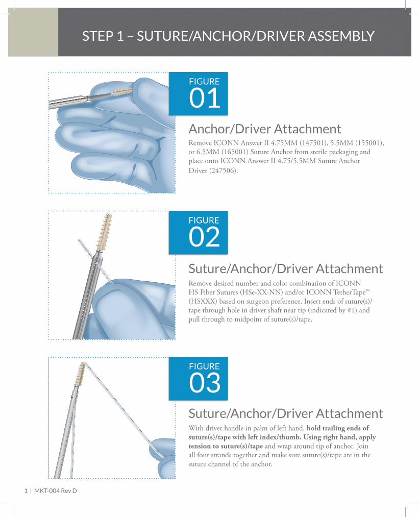
STEP 1 – SUTURE/ANCHOR/DRIVER ASSEMBLY
FIGURE
Remove ICONN Answer II 4.75MM (147501), 5.5MM (155001), or 6.5MM (165001) Suture Anchor from sterile packaging and place onto ICONN Answer II 4.75/5.5MM Suture Anchor Driver (247506).
01Anchor/Driver Attachment
FIGURE
With driver handle in palm of left hand, hold trailing ends of suture(s)/tape with left index/thumb. Using right hand, apply tension to suture(s)/tape and wrap around tip of anchor. Join all four strands together and make sure suture(s)/tape are in the suture channel of the anchor.
03Suture/Anchor/Driver Attachment
FIGURE
Remove desired number and color combination of ICONN HS Fiber Sutures (HSe-XX-NN) and/or ICONN TetherTape™ (HSXXX) based on surgeon preference. Insert ends of suture(s)/tape through hole in driver shaft near tip (indicated by #1) and pull through to midpoint of suture(s)/tape.
02Suture/Anchor/Driver Attachment
STEP 1 – SUTURE/ANCHOR/DRIVER ASSEMBLY
ICO
N An
swer
II4.
75/5
MM
Sut
ure
Anch
or D
river
3
ICO
N A
nsw
er II
4.75
/5M
M S
utur
eAn
chor
Driv
er
4
Anchor/Driver Attachment
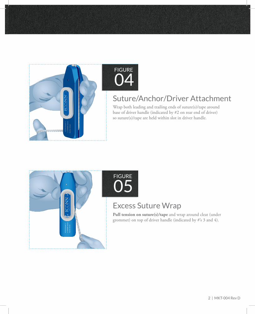
Suture/Anchor/Driver Attachment
Suture/Anchor/Driver Attachment
Wrap both leading and trailing ends of suture(s)/tape around base of driver handle (indicated by #2 on rear end of driver) so suture(s)/tape are held within slot in driver handle.
Suture/Anchor/Driver Attachment
FIGURE
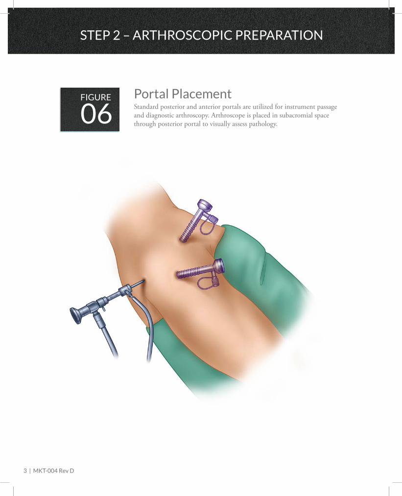
Pull tension on suture(s)/tape and wrap around cleat (under grommet) on top of driver handle (indicated by #’s 3 and 4).
05Excess Suture Wrap
FIGURE
04
2 | MKT-004 Rev D
3 | MKT-004 Rev D
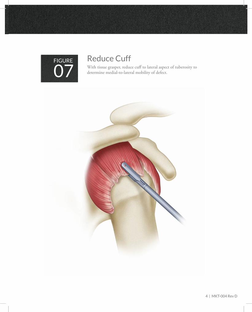
FIGUREStandard posterior and anterior portals are utilized for instrument passage and diagnostic arthroscopy. Arthroscope is placed in subacromial space through posterior portal to visually assess pathology.06Portal Placement
STEP 2 – ARTHROSCOPIC PREPARATION
STEP 2 – ARTHROSCOPIC PREPARATION
FIGUREWith tissue grasper, reduce cuff to lateral aspect of tuberosity to determine medial-to-lateral mobility of defect. 07Reduce Cuff
4 | MKT-004 Rev D
5 | MKT-004 Rev D
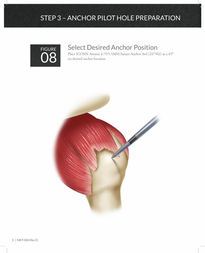
STEP 3 – ANCHOR PILOT HOLE PREPARATION
FIGUREPlace ICONN Answer 4.75/5.5MM Suture Anchor Awl (247502) at a 45⁰ on desired anchor location.08Select Desired Anchor Position
STEP 3 – ANCHOR PILOT HOLE PREPARATION
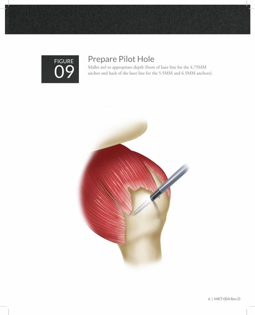
FIGUREMallet awl to appropriate depth (front of laser line for the 4.75MM anchor and back of the laser line for the 5.5MM and 6.5MM anchors).09Prepare Pilot Hole
6 | MKT-004 Rev D
7 | MKT-004 Rev D
STEP 3 – ANCHOR INSERTION
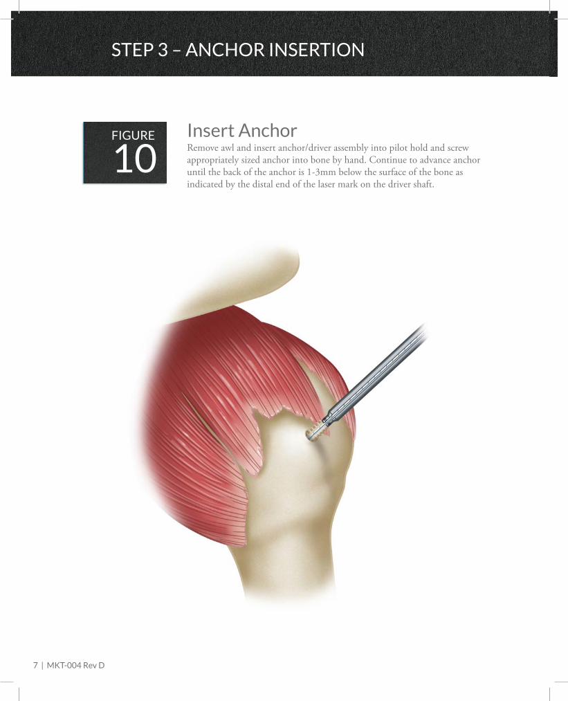
FIGURERemove awl and insert anchor/driver assembly into pilot hold and screw appropriately sized anchor into bone by hand. Continue to advance anchor until the back of the anchor is 1-3mm below the surface of the bone as indicated by the distal end of the laser mark on the driver shaft.
10Insert Anchor
STEP 3 – ANCHOR INSERTION
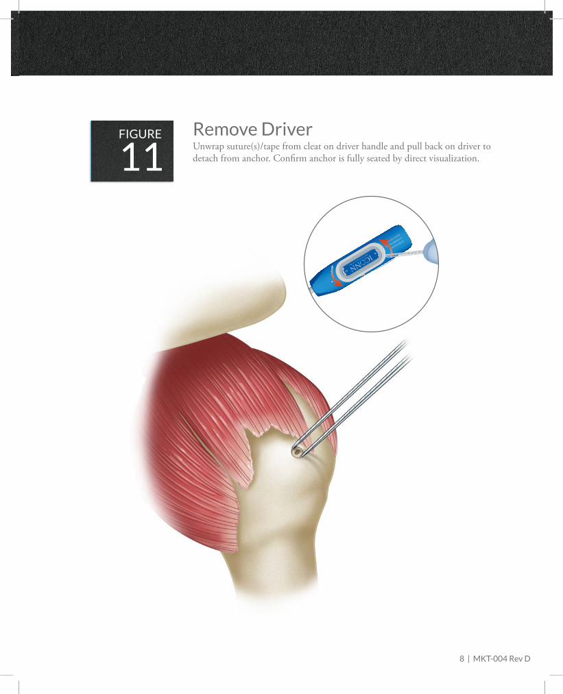
FIGUREUnwrap suture(s)/tape from cleat on driver handle and pull back on driver to detach from anchor. Confirm anchor is fully seated by direct visualization.11Remove Driver
8 | MKT-004 Rev D
ICON Answer II
4.75/5MM Suture
Anchor Driver
3
4
9 | MKT-004 Rev D
STEP 3 – SECURE TORN TISSUE
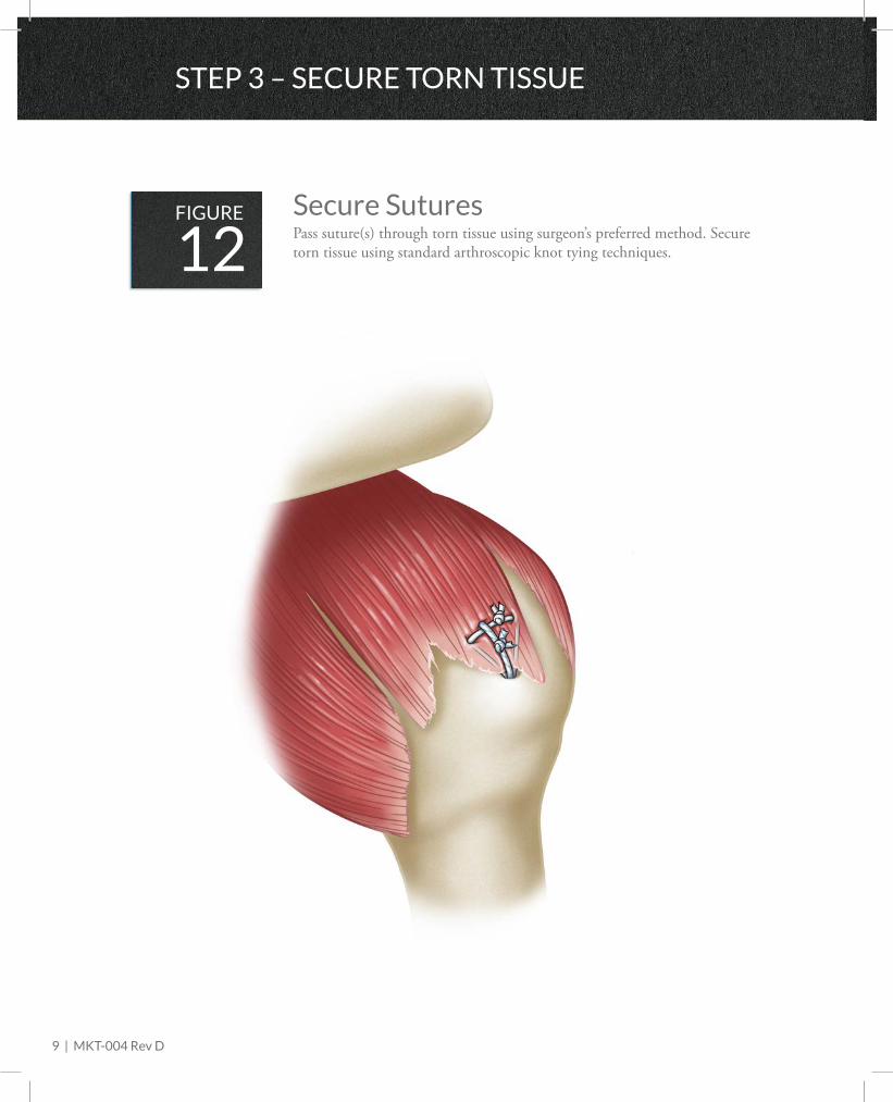
FIGUREPass suture(s) through torn tissue using surgeon’s preferred method. Secure torn tissue using standard arthroscopic knot tying techniques. 12Secure Sutures
STEP 3 – SECURE TORN TISSUE
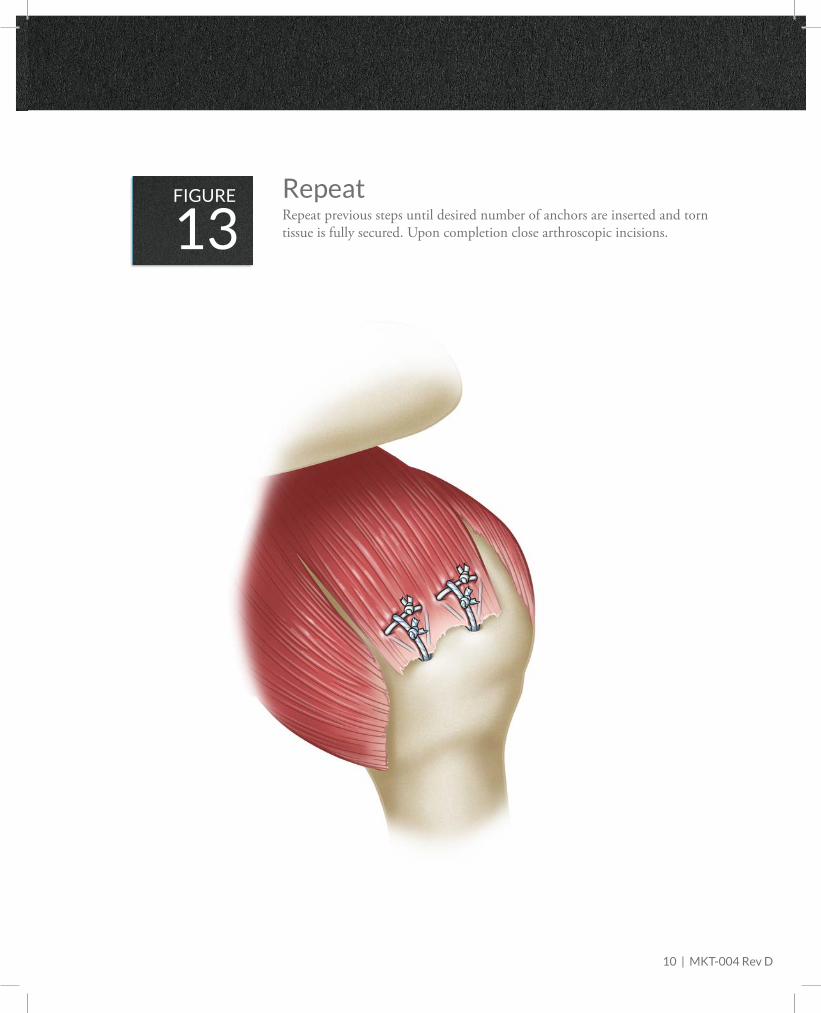
FIGURERepeat previous steps until desired number of anchors are inserted and torn tissue is fully secured. Upon completion close arthroscopic incisions. 13Repeat
10 | MKT-004 Rev D
11 | MKT-004 Rev D
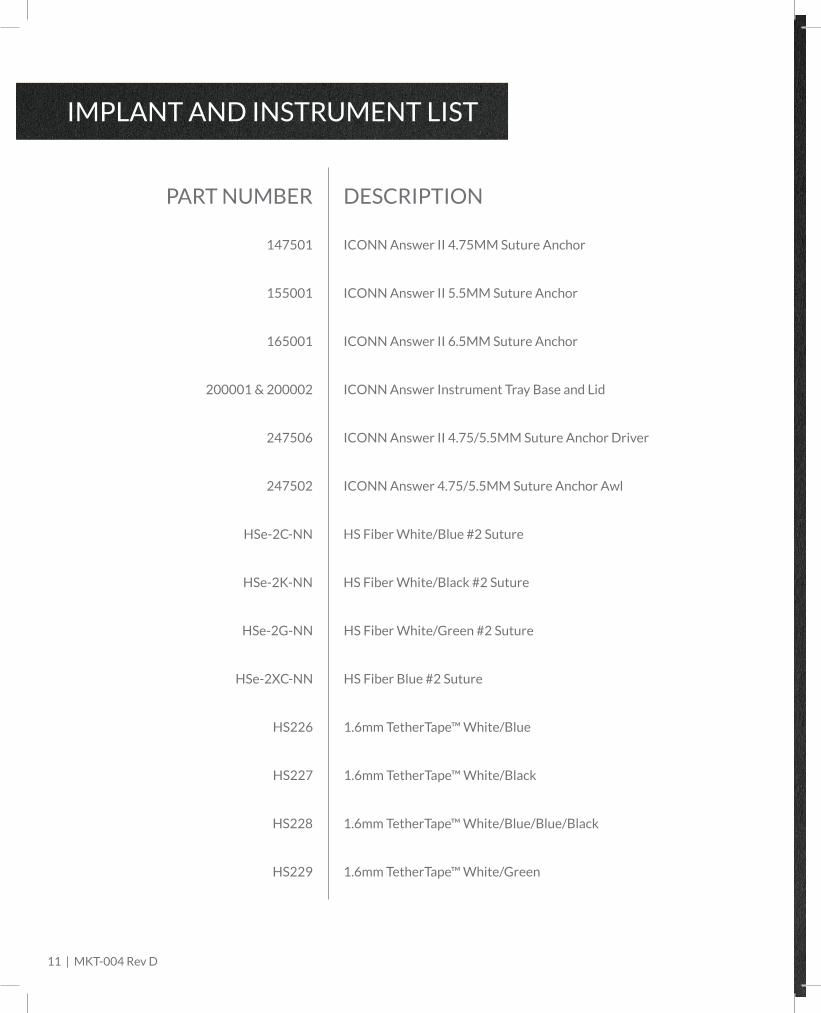
IMPLANT AND INSTRUMENT LIST
DESCRIPTION
ICONN Answer II 4.75MM Suture Anchor
ICONN Answer II 5.5MM Suture Anchor
ICONN Answer Instrument Tray Base and Lid
ICONN Answer II 4.75/5.5MM Suture Anchor Driver
ICONN Answer 4.75/5.5MM Suture Anchor Awl
147501
155001
200001 & 200002
247506
247502
PART NUMBER
HS Fiber White/Blue #2 SutureHSe-2C-NN
HS Fiber White/Black #2 SutureHSe-2K-NN
HS Fiber White/Green #2 SutureHSe-2G-NN
HS Fiber Blue #2 SutureHSe-2XC-NN
1.6mm TetherTape™ White/BlueHS226
ICONN Answer II 6.5MM Suture Anchor165001
1.6mm TetherTape™ White/BlackHS227
1.6mm TetherTape™ White/Blue/Blue/BlackHS228
1.6mm TetherTape™ White/GreenHS229

1
We are designing products, and even more so,
a company which is equally as innovative from
a performance standpoint as from a
cost-reduction standpoint.

ICONN Orthopedics
400 Union Hill Drive, Suite 150
Birmingham, AL 35209
800.391.6476