rotated!tunerkitforgarrettgtturbos.…iftunerdesirestousethe&bigmafhousinginsteadofblowothruboosttube,itwouldbeinstalledbetweenfilterandtubeinabovepicture.&...
TRANSCRIPT
Rotated Tuner Kit for Garrett GT Turbos
031411 Thank you for purchasing the PERRIN performance rotated turbo kit. Installation of this turbo should only be performed by persons experienced in the installation and proper operation of turbochargers and related systems. This kit is designed around using Garrett GT3071R, GT3076R, and GT3582R (utilizing Garrett T3 turbine housing with 3”, 4 bolt
discharge) and Tial 44mm v-‐band style wastegate. Neither the wastegate or turbocharger is included and must be purchased separately.
Warning: An accurate boost gauge and programmable engine management, is required for proper installation and adjustment of this product. Improper installation and use of this product will damage the engine and may result in injury or death! PERRIN performance is in no way responsible for any damages as a result of the installation of this product!
WARNING: This part is designed, manufactured, and sold solely for use on off-‐road and racing vehicles not controlled by federal and or local emissions laws. It is not intended for use on vehicles that operate on public streets and highways. Use of this part on emissions controlled vehicles may be in violation of federal or local law! ASMC, LTD. is not responsible for
any damages as a result of misuse of this part. Check your local laws prior to use or installation.
SPECIAL NOTES: • The use of a factory service manual is highly recommended. http://techinfo.subaru.com. • It is critical that all bolts and nuts are tightened; improper tightening can cause damage or serious injury/death. • The use of penetrating oil will greatly reduce the chances of galling threads on bolts as they are removed. We highly recommend the use of anti-‐seize on treads of all bolts,
when reassembling. • This part is designed to work best with a Blow-‐Thru Boost Tube, or Stand alone ECU that removes the MAF sensor. If a tuner is unfamiliar with Blow-‐Thru boost tube, we also
include our BigMAF housing and a reducer coupler. This is a more traditional style of intake system and it would be installed on filter side of intake tube using supplied coupler. Take note that this requires a Vent to Atmosphere Blow off Valve to be installed.
•
Parts Included with PERRIN Rotated Tuner Kit: • (1) Rotated Turbo Uppipe • (1) Rotated Turbo Downpipe • (1) Aluminum 3” Turbo Intake • (1) 3”-‐4” Silicone Reducer coupler • (1) 2”-‐2.25” Silicone Jog coupler • (1) 2.5”-‐2.25” Silicone Jog coupler • (1) 2.75”-‐3” Silicone reducer coupler • (1) 3.125”ID PERRIN 2pc Filter • (1) PERRIN BigMAF housing • (1) STI oil line with female fitting (WRX oil line with banjo fitting is ordered separately) • (1) Gasket set (T3 inlet, Turbo outlet, GT oil drain, 3” gasket, (2) restrictors) • (2) Banjo Coolant Sets (M14 banjo bolt, M14 banjo fitting, (2) M14 washers) • (1) GT oil drain flange • (1) 3/8NPT-‐ 1/2” barb 45 degree fitting • (4) 10mm x 1.25mm Studs • (4) 10mm x1.25 Nuts • (2) M8 x 20 Socket cap screws • (4) M8 x 25 Socket cap screws • (1) 5/32” tee • (1) 1/2” tee • (2) 1/2”-‐3/8” reducers • (2) 1/2”-‐5/8” reducers • (1) 3/8” connector • (2) 1/2” straight connector • (1) 3/8” Straight connector • (1) 3/8”-‐5/16”connector • (1) T-‐bolt 175 size • (3’) –10 PERRIN PYROshield • (2’) –12 PERRIN PYROshield • (7’) 1/2” Fuel hose • (2’) 1/4” fuel hose • (3’) –6 Pushlock coolant hose • (7’) 5/32” vacuum hose • (20) Zip ties • (1) Size 64 hose clamp • (4) Size 48 hose clamp • (1) Size 36 hose clamp • (2) #3 hose clamps • (2) M4 Phillips pan head screw
Assembling and Preparing for Turbo Installation 1) Remove the factory turbocharger per factory service manual. Take care in removing OEM oil line from turbo. Remove this line from engine to insure it
doesn’t become stressed from over bending. Keep track of both coolant lines, and the oil drain hoses as these connection points are going to be reused later.
2) Remove factory Uppipe bracket and Uppipe from car.
3) Remove OEM inlet hose from engine. This can be done by removing the manifold, or by destroying OEM part. 4) Install supplied oil line onto OEM oil line fitting. Make sure to tighten down or oil leak can occur. Some bending of OEM oil line will be necessary to
clear turbo. Extra care must be taken to ensure the hard line doesn’t break. Wait to bend line once turbo is ready to drop into engine bay. 5) Prepare for Turbo kit mock up. This is done to help align the wastegate to uppipe and downpipe.
• Install 4 studs into uppipe, and install gasket to flange. • Install turbo onto uppipe and install 10mm nuts, but leave 1/2 turn loose. • Install downpipe to turbo (using gasket between connection), and leave M8 bolts 1/2 turn loose. • Install Wastegate to uppipe making sure to install valve seat between wastegate and uppipe. Leave v-‐band clamp loose enough to allow
rotation of wastegate. (Use of Anti-‐Seize on inside of clamps can aid in installation) • Slide wastegate dump tube (on downpipe) up to wastegate outlet. Install and fully tighten v-‐band clamp. • Snug down bolts on downpipe, and then fully tighten bolts on uppipe. This will align wastegate to uppipe and downpipe. Fully tighten
remaining wastegate flange to uppipe. • Remove (4) bolts on downpipe and slide downpipe off of wastegate dump tube and from turbo.
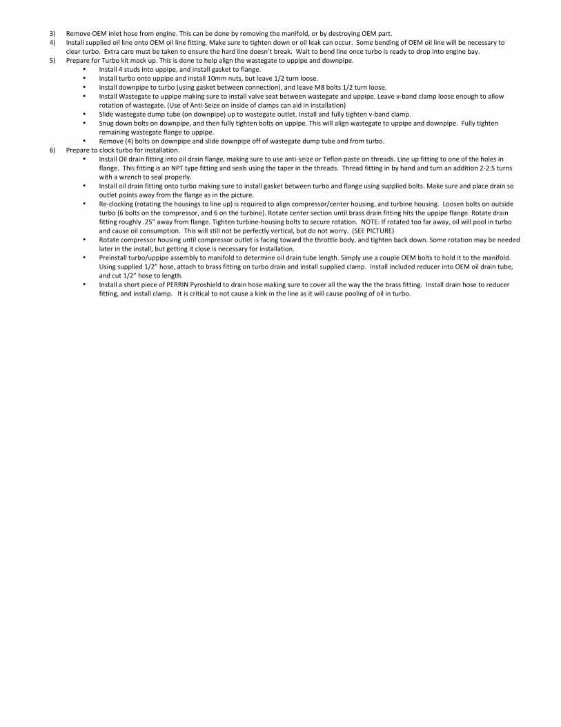
6) Prepare to clock turbo for installation. • Install Oil drain fitting into oil drain flange, making sure to use anti-‐seize or Teflon paste on threads. Line up fitting to one of the holes in
flange. This fitting is an NPT type fitting and seals using the taper in the threads. Thread fitting in by hand and turn an addition 2-‐2.5 turns with a wrench to seal properly.
• Install oil drain fitting onto turbo making sure to install gasket between turbo and flange using supplied bolts. Make sure and place drain so outlet points away from the flange as in the picture.
• Re-‐clocking (rotating the housings to line up) is required to align compressor/center housing, and turbine housing. Loosen bolts on outside turbo (6 bolts on the compressor, and 6 on the turbine). Rotate center section until brass drain fitting hits the uppipe flange. Rotate drain fitting roughly .25” away from flange. Tighten turbine-‐housing bolts to secure rotation. NOTE: If rotated too far away, oil will pool in turbo and cause oil consumption. This will still not be perfectly vertical, but do not worry. (SEE PICTURE)
• Rotate compressor housing until compressor outlet is facing toward the throttle body, and tighten back down. Some rotation may be needed later in the install, but getting it close is necessary for installation.
• Preinstall turbo/uppipe assembly to manifold to determine oil drain tube length. Simply use a couple OEM bolts to hold it to the manifold. Using supplied 1/2” hose, attach to brass fitting on turbo drain and install supplied clamp. Install included reducer into OEM oil drain tube, and cut 1/2” hose to length.
• Install a short piece of PERRIN Pyroshield to drain hose making sure to cover all the way the the brass fitting. Install drain hose to reducer fitting, and install clamp. It is critical to not cause a kink in the line as it will cause pooling of oil in turbo.
Turbocharger taken apart for illustration purposes only!
7) Install PERRIN uppipe to exhaust manifold making sure to use new gasket, and use OEM bolts. Do to the precise nature of the OEM exhaust manifold, you can line up the flanges of the PERRIN uppipe to and torque bolts down. If installing with other aftermarket manifold, leave slightly loose until all other parts are installed.
8) Install oil supply line to turbo oil inlet making sure to install oil line restrictors (SEE PICTURE). Special Note: Included with kit are 2 oil line restrictors, make sure to use them both as shown in the diagram.
9) Install downpipe onto turbo and wastegate dump tube. Snap into transmission hanger and install bolt loosely. Then install and tighten 4 bolts onto turbo exhaust housing.
10) Under car, tighten downpipe to tranny mount and to rear catback exhaust using supplied 3” gasket. This Downpipe requires that the installed catback has a flex joint in the pipe. If catback uses a doughnut type gasket, we recommend flipping it 180 degrees, the installing the catback.
11) Using full length of 3/8” Coolant hose, Install push-‐loc banjo fittings into both ends. Temporarily mount fittings to turbo and determine the cut length of each hose. Keep in mind that there will be 3/8”-‐1/2” reducer fittings installed to allow you to connect hoses to OEM 1/2" coolant hoses. NOTE: We
recommend installing the right side (left if standing in front of the car) hose pointing up and going to the coolant reservoir. The left side (right side if standing in front of car) pointing down going toward block then to coolant hose coming off the engine. It doesn’t matter which hose goes where as long as they are connected to the same coolant hoses the OEM turbo was connected.
12) With hose length set, install supplied 3/8”-‐1/2” reducer fitting to ends of hose and secure with supplied clamps. With hose length set, remove coolant hoses from car.
13) Using smaller diameter Pyroshield, cover both coolant hoses from banjo fitting all the way to the installed adapters. Install supplied clamps over banjo fitting end clamping over Pyroshield and hose at the same time. NOTE: Slide Pyroshield over banjo end is easier than installing over other end.
14) Reinstall fittings making sure to use copper gaskets between turbo and banjo fitting, and between head of banjo bolt and banjo fitting. Align fittings to turbo and tighten to roughly 20ft-‐lbs.
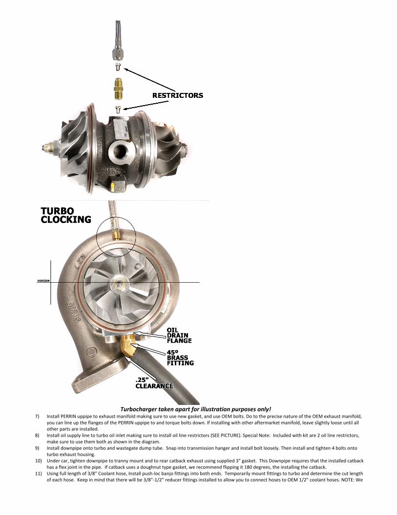
15) Install PERRIN rotated turbo intake kit and boost tube connection. (See Rotated Intake instructions below) 16) Install boost control system to wastegate according to instructions provided with boost controller, or follow Boost Controller Hookup instructions
below. If you are unsure about your boost control system, located lower port on wastegate, and connect to boost source. This will provide 14psi of boost.
17) Start car and check for oil leaks at turbo, at the oil drain tube connection, and coolant line connections. If any leaks are found stop engine and fix. Start engine, and let it warm to normal operating temperature. Once again make sure there are no leaks.
18) Once no leaks are found, using supplied zipties, tie coolant hoses out of way of turbo, and Pyroshield material to oil line, and power steering line. Extra Pyroshield is included for covering misc wires and harnesses.
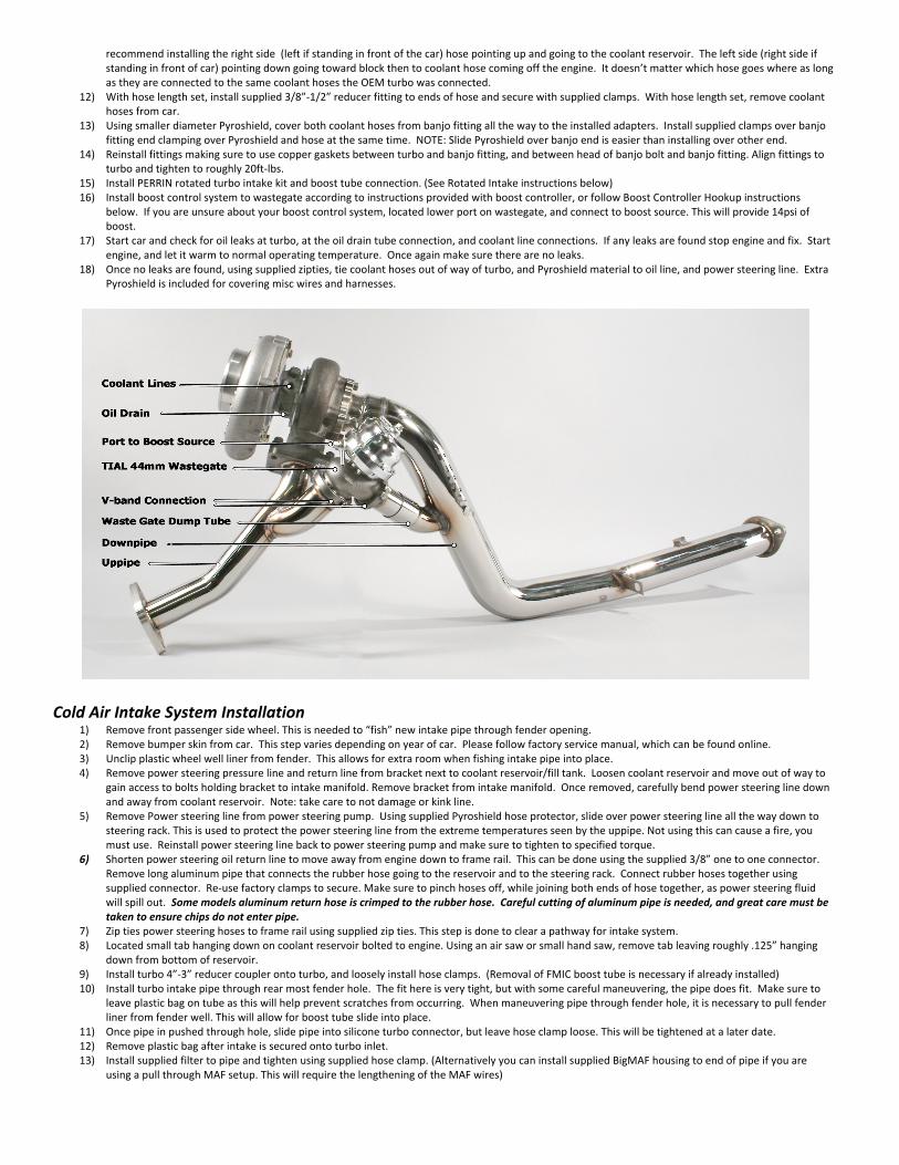
Cold Air Intake System Installation
1) Remove front passenger side wheel. This is needed to “fish” new intake pipe through fender opening. 2) Remove bumper skin from car. This step varies depending on year of car. Please follow factory service manual, which can be found online. 3) Unclip plastic wheel well liner from fender. This allows for extra room when fishing intake pipe into place. 4) Remove power steering pressure line and return line from bracket next to coolant reservoir/fill tank. Loosen coolant reservoir and move out of way to
gain access to bolts holding bracket to intake manifold. Remove bracket from intake manifold. Once removed, carefully bend power steering line down and away from coolant reservoir. Note: take care to not damage or kink line.
5) Remove Power steering line from power steering pump. Using supplied Pyroshield hose protector, slide over power steering line all the way down to steering rack. This is used to protect the power steering line from the extreme temperatures seen by the uppipe. Not using this can cause a fire, you must use. Reinstall power steering line back to power steering pump and make sure to tighten to specified torque.
6) Shorten power steering oil return line to move away from engine down to frame rail. This can be done using the supplied 3/8” one to one connector. Remove long aluminum pipe that connects the rubber hose going to the reservoir and to the steering rack. Connect rubber hoses together using supplied connector. Re-‐use factory clamps to secure. Make sure to pinch hoses off, while joining both ends of hose together, as power steering fluid will spill out. Some models aluminum return hose is crimped to the rubber hose. Careful cutting of aluminum pipe is needed, and great care must be taken to ensure chips do not enter pipe.
7) Zip ties power steering hoses to frame rail using supplied zip ties. This step is done to clear a pathway for intake system. 8) Located small tab hanging down on coolant reservoir bolted to engine. Using an air saw or small hand saw, remove tab leaving roughly .125” hanging
down from bottom of reservoir. 9) Install turbo 4”-‐3” reducer coupler onto turbo, and loosely install hose clamps. (Removal of FMIC boost tube is necessary if already installed) 10) Install turbo intake pipe through rear most fender hole. The fit here is very tight, but with some careful maneuvering, the pipe does fit. Make sure to
leave plastic bag on tube as this will help prevent scratches from occurring. When maneuvering pipe through fender hole, it is necessary to pull fender liner from fender well. This will allow for boost tube slide into place.
11) Once pipe in pushed through hole, slide pipe into silicone turbo connector, but leave hose clamp loose. This will be tightened at a later date. 12) Remove plastic bag after intake is secured onto turbo inlet. 13) Install supplied filter to pipe and tighten using supplied hose clamp. (Alternatively you can install supplied BigMAF housing to end of pipe if you are
using a pull through MAF setup. This will require the lengthening of the MAF wires)
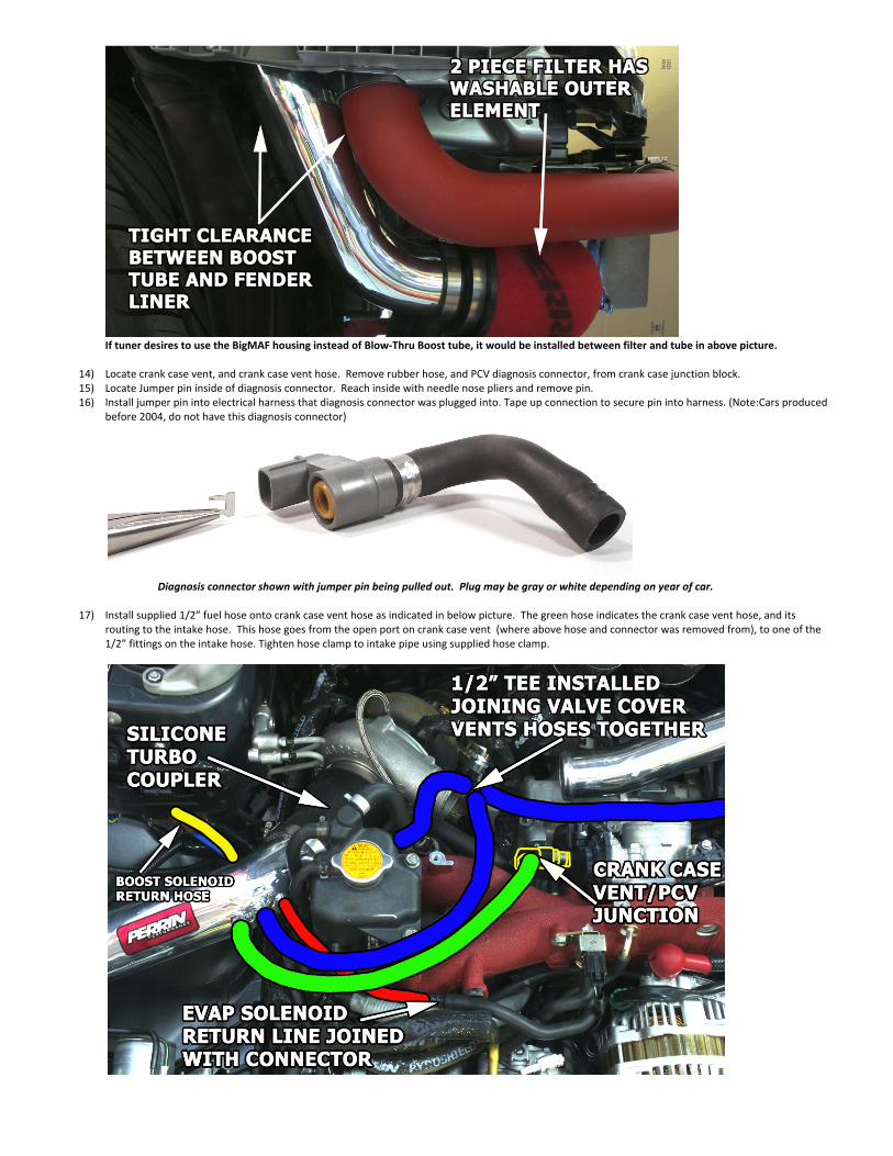
If tuner desires to use the BigMAF housing instead of Blow-‐Thru Boost tube, it would be installed between filter and tube in above picture.
14) Locate crank case vent, and crank case vent hose. Remove rubber hose, and PCV diagnosis connector, from crank case junction block. 15) Locate Jumper pin inside of diagnosis connector. Reach inside with needle nose pliers and remove pin. 16) Install jumper pin into electrical harness that diagnosis connector was plugged into. Tape up connection to secure pin into harness. (Note:Cars produced
before 2004, do not have this diagnosis connector)
Diagnosis connector shown with jumper pin being pulled out. Plug may be gray or white depending on year of car.
17) Install supplied 1/2” fuel hose onto crank case vent hose as indicated in below picture. The green hose indicates the crank case vent hose, and its
routing to the intake hose. This hose goes from the open port on crank case vent (where above hose and connector was removed from), to one of the 1/2” fittings on the intake hose. Tighten hose clamp to intake pipe using supplied hose clamp.
18) Using supplied 1/2” fuel hose, 1/2” tee, and 1/2” connector, join left and right valve cover vent hoses together as shown in diagram below. The blue colored hoses indicate the valve cover vent hoses and their routing. Reuse OEM hose for passenger side connection, and use about 24” of 1/2” fuel hose to reach drivers side. Connect the drivers side valve cover vent hose to 1/2” fuel hose using the supplied 1/2” connector.
19) Connect remaining open tee connection to supplied 1/2” fuel hose, and route to 1/2” spigot on intake pipe. Tighten hose clamp to intake pipe using supplied small hose clamp.
20) Locate EVAP solenoid return hose. This hose connected to OEM turbo intake hose. Using supplied 1/4” fuel hose and 14”-‐3/8” adapter, connect hose to small spigot on intake pipe. This hose is indicated above in red.
21) Locate Boost solenoid return hose. This hose connected to OEM turbo intake hose. Install large diameter OEM rubber hose, and connecter to intake pipe spigot. Shorten small diameter rubber hose to fit to reducer connector. If aftermarket boost controller is being used, this hose may not be needed to be connected to the intake pipe. This hose is indicated above in yellow.
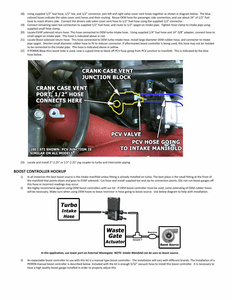
22) If PERRIN Blow-‐thru boost tube is used, now is a good time to block off PCV hose going from PCV junction to manifold. This is indicated by the blue hose below.
23) Locate and install 2”-‐2.25” or 2.5”-‐2.25” jog coupler to turbo and intercooler piping.
BOOST CONTROLLER HOOKUP 1) In all instances the best boost source is the intake manifold unless fitting is already installed on turbo. The best place is the small fitting at the front of
the manifold that points down and goes to EVAP solenoid. Cut hose and install supplied tee and zip tie connection points. (Do not run boost gauges off this hose or incorrect readings may occur.
2) We highly recommend against using OEM boost controllers with our kit. If OEM boost controller must be used, some extending of OEM rubber hoses will be necessary. Make sure when using OEM hoses to leave restrictor in hose going to boost source. Use below diagram to help with installation.
In this application, use lower port on External Wastegate. NOTE: Intake Manifold can be uses as boost source.
3) An expectable boost controller to use with this kit is a manual type boost controller. The installation will vary with different brands. The installation of a
PERRIN manual boost controller is described below. Included with the kit is enough 5/32” vacuum hose to install this boost controller. It is necessary to have a high quality boost gauge installed in order to properly adjust this.
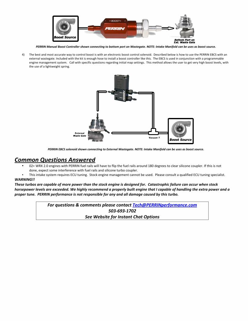
PERRIN Manual Boost Controller shown connecting to bottom port on Wastegate. NOTE: Intake Manifold can be uses as boost source.
4) The best and most accurate way to control boost is with an electronic boost control solenoid. Described below is how to use the PERRIN EBCS with an
external wastegate. Included with the kit is enough hose to install a boost controller like this. The EBCS is used in conjunction with a programmable engine management system. Call with specific questions regarding initial map settings. This method allows the user to get very high boost levels, with the use of a lightweight spring.
PERRIN EBCS solenoid shown connecting to External Wastegate. NOTE: Intake Manifold can be uses as boost source.
Common Questions Answered
• 02+ WRX 2.0 engines with PERRIN fuel rails will have to flip the fuel rails around 180 degrees to clear silicone coupler. If this is not done, expect some interference with fuel rails and silicone turbo coupler.
• This intake system requires ECU tuning. Stock engine management cannot be used. Please consult a qualified ECU tuning specialist. WARNING!! These turbos are capable of more power than the stock engine is designed for. Catastrophic failure can occur when stock horsepower levels are exceeded. We highly recommend a properly built engine that I capable of handling the extra power and a proper tune. PERRIN performance is not responsible for any and all damage caused by this turbo.
For questions & comments please contact [email protected] 503-‐693-‐1702
See Website for Instant Chat Options