rotary table series msu - smc etechcontent2.smcetech.com/pdf/msua2_eu.pdf · 4-108 auto switch...
TRANSCRIPT
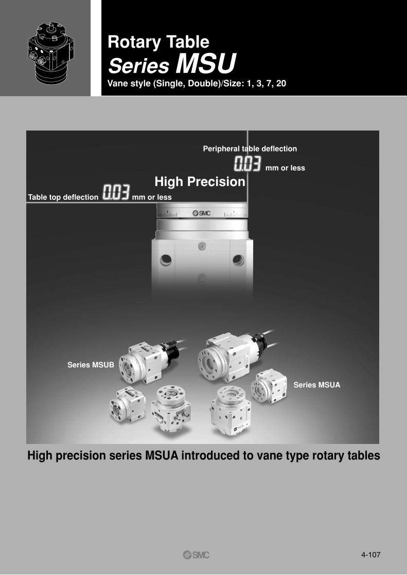
Rotary Table
Series MSUVane style (Single, Double)/Size: 1, 3, 7, 20
High precision series MSUA introduced to vane type rotary tables
Peripheral table deflection
mm or less
Table top deflection mm or less
Series MSUB
Series MSUA
High Precision
4-107
4-108
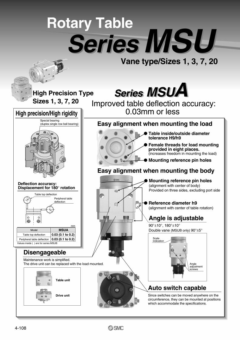
Auto switch capableSince switches can be moved anywhere on the circumference, they can be mounted at positions which accommodate the specifications.
Easy alignment when mounting the load
Angle is adjustable
Rotary Table
90°±10°, 180°±10°Double vane (MSUB only) 90°±5°
Vane type/Sizes 1, 3, 7, 20
Easy alignment when mounting the body
Mounting reference pin holes(alignment with center of body) Provided on three sides, excluding port side
Reference diameter h9(alignment with center of table rotation)
DisengageableMaintenance work is simplified.The drive unit can be replaced with the load mounted.
Scaleindication
Angleadjustmentscrews
Series MSUA High precision/High rigidity
Special bearing(duplex single row ball bearing)
Table unit
Drive unit
Model
Table top deflection
Peripheral table deflection
Values inside ( ) are for series MSUB
MSUA0.03 (0.1 to 0.2) 0.03 (0.1 to 0.2)
Deflection accuracy:Displacement for 180° rotation
Table top deflection
Peripheral tabledeflection
mm
Series MSUA
Series MSU Free-mount type
Can be mounted from three directions: axial, lateral, perpendicular
Axial mounting Perpendicular mountingLateral mounting
Size
1
3
7
20
1
3
7
20
Rotation Vane type Applicable auto switch
D-9, D-T99D-9A, D-S99, S9P
D-R73, D-T79D-R80, D-S79, S7P
D-9, D-T99D-9A, D-S99, S9P
D-R73, D-T79D-R80, D-S79, S7P
Single vane
Single vane∗
Double vane
90°
180°
90°
180°
Series
∗ Double vane is available with 90° rotation setting only.
Series variations
High precisiontype
MSUA
MSUB
Through hole (1)
Through hole (1) Tapped holes (2)
Tapped holes (4)
Bottom mount Top mount
Tapped holes (2)
Tapped holes (4)
Bearing
Single vane
Series MSUB Basic Type Series MSUB
MSUA
MSUB
MSUA
MSUB
MSUA
MSUB
Improved table deflection accuracy: 0.03mm or less
Table inside/outside diameter tolerance H9/h9
Female threads for load mounting provided in eight places.(increases freedom in mounting the load)
Mounting reference pin holes
Rotary actuator with lightweight, compact table for robotic hands
Sizes 1, 3, 7, 20• Single vane and double vane standardized• Double vane has the same dimensions as
single vane (except size 1)
Series MSUHigh Precision TypeSizes 1, 3, 7, 20

4-109
Auto switch capableSince switches can be moved anywhere on the circumference, they can be mounted at positions which accommodate the specifications.
Easy alignment when mounting the load
Angle is adjustable
Rotary Table
90°±10°, 180°±10°Double vane (MSUB only) 90°±5°
Vane type/Sizes 1, 3, 7, 20
Easy alignment when mounting the body
Mounting reference pin holes(alignment with center of body) Provided on three sides, excluding port side
Reference diameter h9(alignment with center of table rotation)
DisengageableMaintenance work is simplified.The drive unit can be replaced with the load mounted.
Scaleindication
Angleadjustmentscrews
Series MSUA High precision/High rigidity
Special bearing(duplex single row ball bearing)
Table unit
Drive unit
Model
Table top deflection
Peripheral table deflection
Values inside ( ) are for series MSUB
MSUA0.03 (0.1 to 0.2) 0.03 (0.1 to 0.2)
Deflection accuracy:Displacement for 180° rotation
Table top deflection
Peripheral tabledeflection
mm
Series MSUA
Series MSU Free-mount type
Can be mounted from three directions: axial, lateral, perpendicular
Axial mounting Perpendicular mountingLateral mounting
Size
1
3
7
20
1
3
7
20
Rotation Vane type Applicable auto switch
D-9, D-T99D-9A, D-S99, S9P
D-R73, D-T79D-R80, D-S79, S7P
D-9, D-T99D-9A, D-S99, S9P
D-R73, D-T79D-R80, D-S79, S7P
Single vane
Single vane∗
Double vane
90°
180°
90°
180°
Series
∗ Double vane is available with 90° rotation setting only.
Series variations
High precisiontype
MSUA
MSUB
Through hole (1)
Through hole (1) Tapped holes (2)
Tapped holes (4)
Bottom mount Top mount
Tapped holes (2)
Tapped holes (4)
Bearing
Single vane
Series MSUB Basic Type Series MSUB
MSUA
MSUB
MSUA
MSUB
MSUA
MSUB
Improved table deflection accuracy: 0.03mm or less
Table inside/outside diameter tolerance H9/h9
Female threads for load mounting provided in eight places.(increases freedom in mounting the load)
Mounting reference pin holes
Rotary actuator with lightweight, compact table for robotic hands
Sizes 1, 3, 7, 20• Single vane and double vane standardized• Double vane has the same dimensions as
single vane (except size 1)
Series MSUHigh Precision TypeSizes 1, 3, 7, 20

4-110
How to Order
M
M
Nominal size (torque)13720
MSUA 1MSUA 3MSUA 7MSUA 20
With auto switch unit
Singlevane
90180
90°180°
WithAuto Switch Unit
WithoutAuto Switch Unit 20 90 S
20 90 S
Free-mount
SUA
D SUA R73
Bearing typeA High precision
S Single vane
Vane type
SymbolApplication Rotation
Connection port positionNilE
Side portsTop ports
Applicable auto switches
Lead wiretype
Parallel cordHeavy duty
Parallel cord
Heavyduty
Heavyduty
Typ
e Electricalentry
Applicable loads
Lead wire length (m)∗
3 wire(NPN)
3 wire(PNP)
3 wire (NPN)
3 wire (PNP)
2 wire
2 wire
24V
24V 12V
12V
DC AC0.5(Nil)
3(L)
None(N)
No
Yes
Yes
No
Yes
Grommet
Grommet
Connector
Grommet
Connector
Grommet
Connector
Grommet
5V, 12V 5V, 12V, 24V5V, 12V,
100V5V, 12V, 24V, 100V
48V,100V
24V, 48V,100V
100V
100V
5V,12V
5V,12V
90
90A
97
93A
T99
T99V
S99
S99V
S9P
S9PV
R73
R73C
R80
R80C
T79
T79C
S79
S7P
ICcircuit
ICcircuit
ICcircuit
ICcircuit
Relay,
PLC
Relay,
PLC
5(Z)
—
—
—
—
—
—
—
—
—
—
—
—
—
—
—
—
—
—
—
—
—
—
—
—
—
—
Ree
d S
olid
sta
te
Sol
id s
tate
R
eed
Operating time ––––– 1.2ms Operating temperature range ––– 5 to 60°C Impact resistance ––– 300m/s² (reed), 1000m/s² (solid state)
∗ Lead wire length symbols 0.5m .... Nil (Example) R73C3m ....... L (Example) R73CL5m ....... Z (Example) R73CZNone ..... N (Example) R73CN
Appl
icab
lem
odel
MDSUA7
MDSUA20
MDSUA1
MDSUA3
Rotation
Number of auto switches1 pc.∗2 pcs.
S
Nil
Type of auto switchWithout auto switch
∗ Select applicable auto switches from the table below.
Nil
Indi
cato
rlig
ht
Load voltageWiring
(output)
Autoswitch
part no.
Available with side ports only, when equipped with switch unit.
∗ For 1 piece, a right hand auto switch is installed.
Rotation adjustment rangeSingle vane: Both ends ±5° each
Order example: MSUA20 single vane type (connection port side position selected)
1. Standard type (without auto switches), rotation 90°, side port positionMSUA20-90S
2. With switch unit (without auto switches), rotation 180°, side port position MDSUA20-180S
3. With switch unit + auto switch R73, rotation 180°, side port position MDSUA20-180S-R73
Rotary Table/Vane Type: High Precision
Series MSUASizes 1, 3, 7, 20

4-111
For 90° rotation
Single vane (S): 80° to 100° adjustable
For 180° rotation
Single vane (S): 170° to 190° adjustable
Adjustment bolt (A)adjustment range(S): 10°
Adjustment bolt (B)adjustment range
(S): 10°
Adjustment bolt (A) adjustment range
Adjustment bolt (B)adjustment range
90°
22.5°
22.5°
Positioning pin hole
Adjustment bolt (A) Adjustment bolt (B)
10° 10°
Positioning pin hole
Adjustment bolt (A) Adjustment bolt (B)
180°
Model 2∗
Single vane Vane type
Rotation 1∗
Fluid
Proof pressure MPa
Ambient and fluid temperature
Operating pressure range MPa
Rotation time adjustment range sec/90°
Shaft load
Bearing
Port position
Port size
Deflection accuracy
Allowable radial load
Allowable thrust load
Allowable moment
MSUA1
90°±10° 180°±10°
Single vane
MSUA3
90°±10° 180°±10°
Single vane
MSUA7
90°±10° 180°±10°
Single vane
MSUA20
90°±10° 180°±10°Air (unlubricated)
5 to 60°C
Special bearings
Side ports or Top ports
0.03mm or less
0.15 to 0.70.2 to 0.7
M3
M3 M5
20N
15N
0.3N⋅m
40N
30N
0.7N⋅m
50N
60N
0.9N⋅m
M5
60N
80N
2.9N⋅m
0.07 to 0.3
1.05 1.5
0.15 to 1.0
∗2. Correspondance to equivalent conventional free-mount typesRotary table
MSUA 1MSUA 3MSUA 7MSUA20
Free-mount/Rotary actuatorCRBUW10CRBUW15CRBUW20CRBUW30
Specifications
Auto switch type
Reed switch
Solid state switch
MDSUB1, 3
D-90/97, D-90A/93A
D-S99, D-T99, D-S9P
MDSUB7, 20
D-R7, R8
D-S7, S7P, T7
Size
1
3
7
20
RotationAuto switch unit
+ Auto switch 2 pcs.
25
30
50
60
Basic weight
Unit: g
90
180
90
180
90
180
90
180
162
161
261.5
259.5
440
436
675
670.5
Single vane
Angle adjustment is possible as shown in the drawings below using adjustment bolts (A) and (B).
Applicable Auto SwitchesTable Rotation Range
Weights
Allowable Loads
Size
1
3
7
20
Allowable radial load (N)
20
40
50
60
Allowable moment (N⋅m)
0.3
0.7
0.9
2.9
Allowable thrust load (N)
15
30
60
80
Do not permit the load and moment applied to the table to exceed the allowable values shown in the table below. (Operation above the allowable values can cause adverse effects on service life, such as play in the table and loss of accuracy.)
Side ports
Top ports
∗1. Single vane 90° can be adjusted to 90°±10° (both ends of rotation ±5° each)Single vane 180° can be adjusted to 180°±10° (both ends of rotation ±5° each)
∗2
How to Order
M
M
Nominal size (torque)13720
MSUA 1MSUA 3MSUA 7MSUA 20
With auto switch unit
Singlevane
90180
90°180°
WithAuto Switch Unit
WithoutAuto Switch Unit 20 90 S
20 90 S
Free-mount
SUA
D SUA R73
Bearing typeA High precision
S Single vane
Vane type
SymbolApplication Rotation
Connection port positionNilE
Side portsTop ports
Applicable auto switches
Lead wiretype
Parallel cordHeavy duty
Parallel cord
Heavyduty
Heavyduty
Typ
e Electricalentry
Applicable loads
Lead wire length (m)∗
3 wire(NPN)
3 wire(PNP)
3 wire (NPN)
3 wire (PNP)
2 wire
2 wire
24V
24V 12V
12V
DC AC0.5(Nil)
3(L)
None(N)
No
Yes
Yes
No
Yes
Grommet
Grommet
Connector
Grommet
Connector
Grommet
Connector
Grommet
5V, 12V 5V, 12V, 24V5V, 12V,
100V5V, 12V, 24V, 100V
48V,100V
24V, 48V,100V
100V
100V
5V,12V
5V,12V
90
90A
97
93A
T99
T99V
S99
S99V
S9P
S9PV
R73
R73C
R80
R80C
T79
T79C
S79
S7P
ICcircuit
ICcircuit
ICcircuit
ICcircuit
Relay,
PLC
Relay,
PLC
5(Z)
—
—
—
—
—
—
—
—
—
—
—
—
—
—
—
—
—
—
—
—
—
—
—
—
—
—
Ree
d S
olid
sta
te
Sol
id s
tate
R
eed
Operating time ––––– 1.2ms Operating temperature range ––– 5 to 60°C Impact resistance ––– 300m/s² (reed), 1000m/s² (solid state)
∗ Lead wire length symbols 0.5m .... Nil (Example) R73C3m ....... L (Example) R73CL5m ....... Z (Example) R73CZNone ..... N (Example) R73CN
Appl
icab
lem
odel
MDSUA7
MDSUA20
MDSUA1
MDSUA3
Rotation
Number of auto switches1 pc.∗2 pcs.
S
Nil
Type of auto switchWithout auto switch
∗ Select applicable auto switches from the table below.
Nil
Indi
cato
rlig
ht
Load voltageWiring
(output)
Autoswitch
part no.
Available with side ports only, when equipped with switch unit.
∗ For 1 piece, a right hand auto switch is installed.
Rotation adjustment rangeSingle vane: Both ends ±5° each
Order example: MSUA20 single vane type (connection port side position selected)
1. Standard type (without auto switches), rotation 90°, side port positionMSUA20-90S
2. With switch unit (without auto switches), rotation 180°, side port position MDSUA20-180S
3. With switch unit + auto switch R73, rotation 180°, side port position MDSUA20-180S-R73
Rotary TableHigh Precision Type Series MSUA
Rotary Table/Vane Type: High Precision
Series MSUASizes 1, 3, 7, 20

4-112
These drawings indicate the condition when the B port is pressurized.Dimensions
ø25
23.5
�31
�38
ø51
8 x M3 depth 5
4 x M4 depth 4
A
C
B
22.5° 4.5
2.5H9
22.5°
Long groove depth 4(positioning pin hole)
16
�31
4.26.5
10.3
5
27
2-4.5 through
Angle adjustment bolt
Adjustment: Max. 7.5
3-R1.5
3-R1.5
3-3H9 long groove depth 2.5
( A , B , C )
4 x M4 depth 82 x M3 depth 4
ø17 H9
2.5
22-4.5 through
27
9
2 x M3
5
0.5B portA port
6.5
4.5
1
231
.52
12.5
378
A port B port9.5
8.5
2 x M3
Top ports/MSUA1-�SE
+0.025
0
+0.0250
3-3H9 depth 3
( A , B , C )
+0.0250
+0.043 0
ø36h9
ø29 0 –0.062
ø9h9 0 –0.036
ø4g6 –0.004–0.012
ø36h9 0 –0.062
ø35h9 0 –0.062
MSUA1MSUA1-�S, SE
Scale: 70%
Series MSUA
4-113
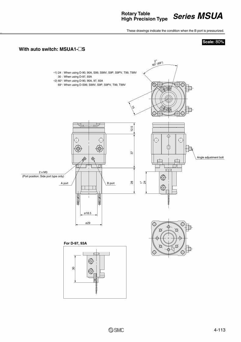
Scale: 80%
These drawings indicate the condition when the B port is pressurized.
Angle adjustment bolt
241∗
2∗
60° (69°)
15
12.5
3728
ø18.5
ø29
2 x M3(Port position: Side port type only)
A port B port
30
For D-97, 93A
With auto switch: MSUA1-�S
∗1) 24 : When using D-90, 90A, S99, S99V, S9P, S9PV, T99, T99V30 : When using D-97, 93A
∗2) 60° : When using D-90, 90A, 97, 93A69° : When using D-S99, S99V, S9P, S9PV, T99, T99V
Rotary TableHigh Precision Type Series MSUA
These drawings indicate the condition when the B port is pressurized.Dimensions
ø25
23.5
�31
�38
ø51
8 x M3 depth 5
4 x M4 depth 4
A
C
B
22.5° 4.5
2.5H9
22.5°
Long groove depth 4(positioning pin hole)
16
�31
4.26.5
10.3
5
27
2-4.5 through
Angle adjustment bolt
Adjustment: Max. 7.5
3-R1.5
3-R1.5
3-3H9 long groove depth 2.5
( A , B , C )
4 x M4 depth 82 x M3 depth 4
ø17 H9
2.5
22-4.5 through
27
9
2 x M3
5
0.5B portA port
6.5
4.5
1
231
.52
12.5
378
A port B port9.5
8.5
2 x M3
Top ports/MSUA1-�SE
+0.025
0
+0.0250
3-3H9 depth 3
( A , B , C )
+0.0250
+0.043 0
ø36h9
ø29 0 –0.062
ø9h9 0 –0.036
ø4g6 –0.004–0.012
ø36h9 0 –0.062
ø35h9 0 –0.062
MSUA1MSUA1-�S, SE
Scale: 70%

4-114
These drawings indicate the condition when the B port is pressurized.Dimensions
22.5°
22.5°
�36
3-3H9 long groove depth 2.5
( A , B , C )
4 x M4 depth 8
ø21H9
2-4.5 through
2 x M5
B portA port
A port B port
2 x M3
Top ports/MSUA3-�SE
+0.025
0
+0.0250
3-3H9 depth 3
( A , B , C )
+0.025 0
+0.0520
ø42h9
ø34
0 –0.062
ø12h9 0–0.043
ø5g6 –0.004–0.012
ø42h9 0–0.062
ø41h9 0–0.062
ø30 �44
�3627
29
11
29
ø58
8 x M4 depth 7
4 x M4 depth 5.5
5
3H9
Long groove depth 5(positioning pin hole)
55
811
2-4.5 through
3-R1.5
3-R1.5
18.3
Angle adjustment bolt
Adjustment: Max. 8.2
3
6
0.5
2.5
81.
5
236
3 15.5
459
11
10
B
C
6
A
MSUA3MSUA3-�S, SE
Scale: 70%
Series MSUA

4-115
Scale: 80%
These drawings indicate the condition when the B port is pressurized.
Angle adjustment bolt
2∗60° (69°)
ø18.5
ø34
2 x M5(Port position: Side port type only)
A port B port
1∗ 24
15
15.5
4529
30
D-97, 93A
With auto switch: MDSUA3-�S
∗1) 24 : When using D-90, 90A, S99, S99V, S9P, S9PV, T99, T99V30 : When using D-97, 93A
∗2) 60° : When using D-90, 90A, 97, 93A69° : When using D-S99, S99V, S9P, S9PV, T99, T99V
Rotary TableHigh Precision Type Series MSUA
These drawings indicate the condition when the B port is pressurized.Dimensions
22.5°
22.5°
�36
3-3H9 long groove depth 2.5
( A , B , C )
4 x M4 depth 8
ø21H9
2-4.5 through
2 x M5
B portA port
A port B port
2 x M3
Top ports/MSUA3-�SE
+0.025
0
+0.0250
3-3H9 depth 3
( A , B , C )
+0.025 0
+0.0520
ø42h9
ø34
0 –0.062
ø12h9 0–0.043
ø5g6 –0.004–0.012
ø42h9 0–0.062
ø41h9 0–0.062
ø30 �44
�3627
29
11
29
ø58
8 x M4 depth 7
4 x M4 depth 5.5
53H9
Long groove depth 5(positioning pin hole)
55
811
2-4.5 through
3-R1.5
3-R1.5
18.3
Angle adjustment bolt
Adjustment: Max. 8.2
3
6
0.5
2.5
81.
5
236
3 15.5
459
11
10
B
C
6
A
MSUA3MSUA3-�S, SE
Scale: 70%

4-116
Scale: 60%
These drawings indicate the condition when the B port is pressurized.Dimensions
22.5°
�41
3-4H9 long groove depth 3
( A , B , C )
4 x M5 depth 10
ø26H9
2-5.5 through
2 x M5
B portA port
A port B port
2 x M5
Top ports/MSUA7-�SE
+0.025
0
+0.0300
3-4H9 depth 4
( A , B , C )
+0.0300
+0.0520
ø48h9
ø42
0–0.062
ø14h9 0–0.043
ø6g6 –0.004–0.012
ø48h9 0–0.062
ø47h9 0–0.062
�50
�41
3H9
Long groove depth 5(positioning pin hole)
2-5.5 through Angle adjustment bolt
33
ø37
ø67
5
4 x M5 depth 7
8 x M4 depth 8
22.5°
B
C
3610
.513
76
22.3
3-R2
3-R2
Adjustment: Max.10.2
4
36
11
7
0.5
3
10.5
4.5
19
1.5
443
1058
.5
6
14
13
A
MSUA7MSUA7-�S, SE
Series MSUA

4-117 7
Scale: 60%
These drawings indicate the condition when the B port is pressurized.
65°
ø25
ø42
A port B port
34.5
26.
5
Connector type
4
8
30
25.5
(34
.5: C
onne
ctor
type
)
20.5
(26
.5: C
onne
ctor
type
)
Angle adjustment bolt
19
2 x M5(Port position: Side port type only)
58.5
30
Connector type
With auto switch: MDSUA7-�S
Rotary TableHigh Precision Type Series MSUA
Scale: 60%
These drawings indicate the condition when the B port is pressurized.Dimensions
22.5°
�41
3-4H9 long groove depth 3
( A , B , C )
4 x M5 depth 10
ø26H9
2-5.5 through
2 x M5
B portA port
A port B port
2 x M5
Top ports/MSUA7-�SE
+0.025
0
+0.0300
3-4H9 depth 4
( A , B , C )
+0.0300
+0.0520
ø48h9
ø42
0–0.062
ø14h9 0–0.043
ø6g6 –0.004–0.012
ø48h9 0–0.062
ø47h9 0–0.062
�50
�41
3H9
Long groove depth 5(positioning pin hole)
2-5.5 through Angle adjustment bolt
33
ø37
ø67
5
4 x M5 depth 7
8 x M4 depth 8
22.5°
B
C
36
10.5
13
76
22.3
3-R2
3-R2
Adjustment: Max.10.2
4
36
11
7
0.5
3
10.5
4.5
19
1.5
443
1058
.5
6
14
13
A
MSUA7MSUA7-�S, SE

4-118
Scale: 50%
These drawings indicate the condition when the B port is pressurized.Dimensions
22.5°
�48
3-4H9 long groove depth 3
( A , B , C )
4 x M6 depth 11
ø30H9
2-6.6 through
2 x M5
B port
A port
A port B port
2 x M5
Top ports/MSUA20-�SE
+0.025
0
+0.0300
3-4H9 depth 4
( A , B , C )
+0.0300
+0.052 0
ø53.5h9
ø50
0–0.074
ø16h9 0–0.043
ø8g6 –0.005–0.014
ø53.5h9 0–0.074
ø52h9 0–0.074
�59
�48
3H9
Long groove depth 5(positioning pin hole)
2-6.6 through
Angle adjustment bolt
4 x M6 depth 7
8 x M5 depth 10
22.5°
ø42
38
ø78
5
B
C
43
10.5
16
76
3-R2
3-R2
23Adjustment: Max. 10.3
A
5
43
13
8
1
4
10.5
5
21.5
2
464
7213
14
15.5
6
MSUA20MSUA20-�S, SE
Series MSUA

4-119 7
Scale: 50%
65°
ø25
ø50
A port B port
Connector type
25.5
(34
.5: C
onne
ctor
type
)
20.5
(26
.5: C
onne
ctor
type
)
Angle adjustment bolt
2 x M5(Port position: Side port type only)
31
8
4
21.5
7231
34.5
26.5
Connector type
With auto switch: MDSUA20-�S
These drawings indicate the condition when the B port is pressurized.
Rotary TableHigh Precision Type Series MSUA
Scale: 50%
These drawings indicate the condition when the B port is pressurized.Dimensions
22.5°
�48
3-4H9 long groove depth 3
( A , B , C )
4 x M6 depth 11
ø30H9
2-6.6 through
2 x M5
B port
A port
A port B port
2 x M5
Top ports/MSUA20-�SE
+0.025
0
+0.0300
3-4H9 depth 4
( A , B , C )
+0.0300
+0.052 0
ø53.5h9
ø50
0–0.074
ø16h9 0–0.043
ø8g6 –0.005–0.014
ø53.5h9 0–0.074
ø52h9 0–0.074
�59
�48
3H9
Long groove depth 5(positioning pin hole)
2-6.6 through
Angle adjustment bolt
4 x M6 depth 7
8 x M5 depth 10
22.5°
ø42
38
ø78
5
B
C
43
10.5
16
76
3-R2
3-R2
23
Adjustment: Max. 10.3
A
5
43
13
8
1
4
10.5
5
21.5
2
464
7213
14
15.5
6
MSUA20MSUA20-�S, SE

4-120
Construction
Internal construction with auto switch
MDSUA1, 3 MDSUA7, 20
No.
1234567891011121314151617181920212223
Description
Body A
Body B
Body C
Vane shaft
Stopper
Stopper seal
Table
Stopper lever
Stopper guide
Lever retainer
Bearing retainer
Bearing
Special bearing
Back-up ring
O-ring
Adjustment bolt
Hexagon nut
Hexagon socket head cap screw
Hexagon socket head cap screw
Hexagon socket head cap screw
Button bolt
Hexagon socket head set screw
Label
Material
Aluminum alloy
Aluminum alloy
Aluminum alloy
Stainless steel (MSUA20 is carbon steel)
Resin
NBR
Aluminum alloy
Carbon steel
Stainless steel
Carbon steel
Aluminum alloy
High carbon chrome bearing steel
High carbon chrome bearing steel
Stainless steel
NBR
Carbon steel
Carbon steel
Stainless steel
Stainless steel
Carbon steel
Carbon steel
Stainless steel
Note
Light gray color
Light gray color
Light gray color
Single vane
Single vane
Light gray color
Light gray color
SE type only
Model
MDSUA 1
MDSUA 3
MDSUA 7
MDSUA20
Auto switch unit part number
P211070-1
P211090-1
P211060-1
P211080-1
Auto switch block unit
MDSUA1, 3 MDSUA7, 20
Left-handedRight-handed Combination left & right-handed
Part no.: P211060-8Part no.: P211070-9Part no.: P211070-8
∗ A switch block unit is the assembly required to mount one auto switch on a switch unit.
∗ The plug 22 is used only when the connection port is type SE.
Auto switch unit
180° (Indicates intermediate position)
90°(Indicates A port pressurized)
Single vane
Parts list
A port B port
∗ Auto switches are not included with switch units.
Series MSUA

4-121
Construction
Internal construction with auto switch
MDSUA1, 3 MDSUA7, 20
No.
1234567891011121314151617181920212223
Description
Body A
Body B
Body C
Vane shaft
Stopper
Stopper seal
Table
Stopper lever
Stopper guide
Lever retainer
Bearing retainer
Bearing
Special bearing
Back-up ring
O-ring
Adjustment bolt
Hexagon nut
Hexagon socket head cap screw
Hexagon socket head cap screw
Hexagon socket head cap screw
Button bolt
Hexagon socket head set screw
Label
Material
Aluminum alloy
Aluminum alloy
Aluminum alloy
Stainless steel (MSUA20 is carbon steel)
Resin
NBR
Aluminum alloy
Carbon steel
Stainless steel
Carbon steel
Aluminum alloy
High carbon chrome bearing steel
High carbon chrome bearing steel
Stainless steel
NBR
Carbon steel
Carbon steel
Stainless steel
Stainless steel
Carbon steel
Carbon steel
Stainless steel
Note
Light gray color
Light gray color
Light gray color
Single vane
Single vane
Light gray color
Light gray color
SE type only
Model
MDSUA 1
MDSUA 3
MDSUA 7
MDSUA20
Auto switch unit part number
P211070-1
P211090-1
P211060-1
P211080-1
Auto switch block unit
MDSUA1, 3 MDSUA7, 20
Left-handedRight-handed Combination left & right-handed
Part no.: P211060-8Part no.: P211070-9Part no.: P211070-8
∗ A switch block unit is the assembly required to mount one auto switch on a switch unit.
∗ The plug 22 is used only when the connection port is type SE.
Auto switch unit
180° (Indicates intermediate position)
90°(Indicates A port pressurized)
Single vane
Parts list
A port B port
∗ Auto switches are not included with switch units.

4-122
How to Order
M
M
13720
With auto switch unit
Rotation
Singlevane
Doublevane
90180
90°180°
90 90°
SNil
20 90 S
20 90 S
Free-mount
SUB
D SUB R73
Bearing typeB Basic type
SD
Single vaneDouble vane
Vane type
Rotation adjustment rangeSingle vane: Both ends ±5° eachDouble vane: Both ends ±2.5° each
Nil
Connection port positionNilE
Applicable auto switchesAuto switch
part no.
Load voltage
24V
24V 12V
12V
DC AC3
(L)None(N)
5V, 12V 5V, 12V, 24V5V, 12V,
100V5V, 12V, 24V, 100V
48V,100V
24V, 48V,100V
100V
100V
5V,12V
5V,12V
90
90A
97
93A
T99
T99V
S99
S99V
S9P
S9PV
R73
R73C
R80
R80C
T79
T79C
S79
S7P
5(Z)
MDSUB1
MDSUB3
MDSUB7
MDSUB20
Side portsTop ports
WithAuto Switch Unit
WithoutAuto Switch Unit
Nominal size (torque)MSUB 1MSUB 3MSUB 7MSUB 20 SymbolApplication Rotation
Number of auto switches1 pc.∗2 pcs.
Type of auto switchWithout auto switch
∗ Select applicable auto switches from the table below.
Typ
eR
eed
Sol
id s
tate
S
olid
sta
te
Ree
d
Electricalentry
Grommet
Grommet
Connector
Grommet
Connector
Grommet
Connector
Grommet
Appl
icab
lem
odel
3 wire(NPN)
3 wire(PNP)
3 wire (NPN)
3 wire (PNP)
2 wire
2 wire
No
Yes
Yes
No
Yes
Indi
cato
rlig
ht Wiring(output)
Leadwiretype
Parallel cord
Heavy duty
Parallel cord
Heavy duty
Heavy duty
Applicableloads
Lead wire length (m)∗
0.5(Nil)
ICcircuit
ICcircuit
ICcircuit
ICcircuit
Relay,PLC
Relay,PLC
—
—
—
—
—
—
—
—
—
—
—
—
—
—
—
—
—
—
—
—
—
—
—
—
—
—
Available with side ports only, when equipped with switch unit.
∗ For 1 piece, a right hand auto switch is installed.
Order example: MSUA20 single vane type (connection port side position selected)
1. Standard type (without auto switches), rotation 90°, side port positionMSUB20-90S
2. With switch unit (without auto switches), rotation 180°,side port position MDSUB20-180S
3. With switch unit + auto switch R73, rotation 180°, side port position MDSUB20-180S-R73
Operating time ––––– 1.2ms Operating temperature range ––– 5 to 60°C Impact resistance ––– 300m/s² (reed), 1000m/s² (solid state)
∗ Lead wire length symbols 0.5m .... Nil (Example) R73C3m ....... L (Example) R73CL5m ....... Z (Example) R73CZNone ..... N (Example) R73CN
Rotary Table/Vane Type: Basic
Series MSUBSizes 1, 3, 7, 20

4-123
B
MDSUB1, 3
D-90/97, D-90A/93A
D-S99, D-T99, D-S9P
MDSUB7, 20
D-R7, R8
D-S7, D-S7P, T7
90
180
90
180
90
180
90
180
Single vane
145
140
230
225
360
355
510
505
Double vane
150
240
375
580
Unit: g
Size
1
3
7
20
Allowable radial load (N)
20
40
50
60
Allowable moment (N⋅m)
0.3
0.7
0.9
2.9
Allowable thrust load (N)
15
30
60
80
10
15
30
40
A
Model 3∗
Single vane Vane type
Rotation 1∗
Fluid
Proof pressure MPa
Ambient and fluid temperature
Operating pressure range MPa
Rotation time adjustment range sec/90°
Shaft load
Bearing
Port position
Port size
Allowable radial load
Allowable thrust load 2∗
Allowable moment
Side ports
Top ports
MSUB1
90°±10° 180°±10° 90°±5°
Double vane Single vane
MSUB3
90°±10° 180°±10° 90°±5°
Double vane Single vane
MSUB7
90°±10° 180°±10° 90°±5°
Double vane Single vane
MSUB20
90°±10° 180°±10° 90°±5°
Double vane
Air (unlubricated)
5 to 60°C
Bearings
Side ports or Top ports
0.15 to 0.70.2 to 0.7
M3
M3 M5
20N
15N
10N
0.3N⋅m
40N
30N
15N
0.7N⋅m
50N
60N
30N
0.9N⋅m
M5
60N
80N
40N
2.9N·m
0.07 to 0.3
1.05 1.5
0.15 to 1.0
∗3. Correspondence to equivalent conventional free-mount types
Rotary tableMSUB 1MSUB 3MSUB 7MSUB20
Free-mount rotary actuatorCRBUW10CRBUW15CRBUW20CRBUW30
For 90° rotation
Single vane (S): 80° to 100° adjustable
Double vane (D): 85° to 95° adjustable
For 180° rotation
Single vane (S): 170° to 190° adjustable
∗ The double vane type is not available with 180° rotation.
Adjustment bolt (A) adjustment range
(S): 10°(D): 5°
Adjustment bolt (B) adjustment range (S): 10° (D): 5°
90°
A B
22.5°
22.5°
Positioning pin hole
10° 10°
180°
Specifications
Table Rotation RangeAngle adjustment is possible as shown in the drawings below using adjustment bolts (A) and (B).
Adjustment bolt (A) Adjustment bolt (B)
Adjustment bolt (A) adjustment range
Adjustment bolt (B) adjustment range
Positioning pin hole
Adjustment bolt (A) Adjustment bolt (B)
Auto switch type
Reed switch
Solid state switch
Applicable Auto Switches
Size
1
3
7
20
RotationAuto switch unit
+Auto switch 2 pcs.
25
30
50
60
Weights
Basic weight
Allowable LoadsDo not permit the load and moment applied to the table to exceed the allowable values shown in the table below. (Operation above the allowable values can cause adverse effects on service life, such as play in the table and loss of accuracy.)
∗1. Single vane 90° type can be adjusted to 90°±10° (both ends of rotation ±5° each)Single vane 180° type can be adjusted to 180°±10° (both ends of rotation ±5° each)Double vane 90° type can be adjusted to 90°±5° (both ends of rotation ±2.5° each)• Rotation angles other than 90° and 180° (single vane) are available by special order.
∗2. The allowable thrust load is directional. For details refer to the allowable load table below.
Rotary Table Series MSUB
How to Order
M
M
13720
With auto switch unit
Rotation
Singlevane
Doublevane
90180
90°180°
90 90°
SNil
20 90 S
20 90 S
Free-mount
SUB
D SUB R73
Bearing typeB Basic type
SD
Single vaneDouble vane
Vane type
Rotation adjustment rangeSingle vane: Both ends ±5° eachDouble vane: Both ends ±2.5° each
Nil
Connection port positionNilE
Applicable auto switchesAuto switch
part no.
Load voltage
24V
24V 12V
12V
DC AC3
(L)None(N)
5V, 12V 5V, 12V, 24V5V, 12V,
100V5V, 12V, 24V, 100V
48V,100V
24V, 48V,100V
100V
100V
5V,12V
5V,12V
90
90A
97
93A
T99
T99V
S99
S99V
S9P
S9PV
R73
R73C
R80
R80C
T79
T79C
S79
S7P
5(Z)
MDSUB1
MDSUB3
MDSUB7
MDSUB20
Side portsTop ports
WithAuto Switch Unit
WithoutAuto Switch Unit
Nominal size (torque)MSUB 1MSUB 3MSUB 7MSUB 20 SymbolApplication Rotation
Number of auto switches1 pc.∗2 pcs.
Type of auto switchWithout auto switch
∗ Select applicable auto switches from the table below.
Typ
eR
eed
Sol
id s
tate
S
olid
sta
te
Ree
d
Electricalentry
Grommet
Grommet
Connector
Grommet
Connector
Grommet
Connector
Grommet
Appl
icab
lem
odel
3 wire(NPN)
3 wire(PNP)
3 wire (NPN)
3 wire (PNP)
2 wire
2 wire
No
Yes
Yes
No
Yes
Indi
cato
rlig
ht Wiring(output)
Leadwiretype
Parallel cord
Heavy duty
Parallel cord
Heavy duty
Heavy duty
Applicableloads
Lead wire length (m)∗
0.5(Nil)
ICcircuit
ICcircuit
ICcircuit
ICcircuit
Relay,PLC
Relay,PLC
—
—
—
—
—
—
—
—
—
—
—
—
—
—
—
—
—
—
—
—
—
—
—
—
—
—
Available with side ports only, when equipped with switch unit.
∗ For 1 piece, a right hand auto switch is installed.
Order example: MSUA20 single vane type (connection port side position selected)
1. Standard type (without auto switches), rotation 90°, side port positionMSUB20-90S
2. With switch unit (without auto switches), rotation 180°,side port position MDSUB20-180S
3. With switch unit + auto switch R73, rotation 180°, side port position MDSUB20-180S-R73
Operating time ––––– 1.2ms Operating temperature range ––– 5 to 60°C Impact resistance ––– 300m/s² (reed), 1000m/s² (solid state)
∗ Lead wire length symbols 0.5m .... Nil (Example) R73C3m ....... L (Example) R73CL5m ....... Z (Example) R73CZNone ..... N (Example) R73CN
Rotary Table/Vane Type: Basic
Series MSUBSizes 1, 3, 7, 20

4-124
MSUB1 (Single vane)
MSUB1-�S, SE
These drawings indicate the condition when the B port is pressurized.Dimensions
∗ If the adjustment bolt is removed, rotation will be approximately 270° for the single vane type and 100° for the double vane type. Since this will make it impossible to satisfy the specifications, operate with adjustment within the range of maximum values.
Series MSUB

4-125
With auto switch: MDSUB1-�S
These drawings indicate the condition when the B port is pressurized.
D-97, 93A
∗1) When using 24 : D-90, 90A, S99(V), T99(V), S9P(V) When using 30 : D-97, 93A
∗2) When using 60° : D-90, 90A, 97, 93A When using 69° : D-S99(V), T99(V), S9P(V)
∗ If the adjustment bolt is removed, rotation will be approximately 270° for the single vane type and 100° for the double vane type. Since this will make it impossible to satisfy the specifications, operate with adjustment within the range of maximum values.
MSUB1 (Single vane)
MSUB1-�S, SE
These drawings indicate the condition when the B port is pressurized.Dimensions
∗ If the adjustment bolt is removed, rotation will be approximately 270° for the single vane type and 100° for the double vane type. Since this will make it impossible to satisfy the specifications, operate with adjustment within the range of maximum values.
Rotary Table Series MSUB

4-126
These drawings indicate the condition when the B port is pressurized.
MSUB1 (Double vane)
MSUB1-�D
Dimensions
∗ If the adjustment bolt is removed, rotation will be approximately 270° for the single vane type and 100° for the double vane type. Since this will make it impossible to satisfy the specifications, operate with adjustment within the range of maximum values.
Series MSUB

4-127
With auto switch: MDSUB1-�D
These drawings indicate the condition when the B port is pressurized.
D-97, 93A
∗1) When using 24 : D-90, 90A, S99(V), T99(V), S9P(V)When using 30 : D-97, 93A
∗2) When using 60° : D-90, 90A, 97, 93A When using 69° : D-S99(V), T99(V), S9P(V)
∗ If the adjustment bolt is removed, rotation will be approximately 270° for the single vane type and 100° for the double vane type. Since this will make it impossible to satisfy the specifications, operate with adjustment within the range of maximum values.
These drawings indicate the condition when the B port is pressurized.
MSUB1 (Double vane)
MSUB1-�D
Dimensions
∗ If the adjustment bolt is removed, rotation will be approximately 270° for the single vane type and 100° for the double vane type. Since this will make it impossible to satisfy the specifications, operate with adjustment within the range of maximum values.
Rotary Table Series MSUB

4-128
These drawings indicate the condition when the B port is pressurized.
MSUB3 (Single vane, Double vane)
MSUB3-�S, D
Dimensions
The outside drawings show the single vane type, but only the position of the chamfered sections shown in the above drawings differs for single and double vane.
∗ If the adjustment bolt is removed, rotation will be approximately 270° for the single vane type and 100° for the double vane type. Since this will make it impossible to satisfy the specifications, operate with adjustment within the range of maximum values.
Series MSUB

4-129
With auto switch: MDSUB3
D-97, 93A
These drawings indicate the condition when the B port is pressurized.
∗1) When using 24 : D-90, 90A, S99(V), T99(V), S9P(V) When using 30 : D-97, 93A
∗2) When using 60° : D-90, 90A, 97, 93A When using 69° : D-S99(V), T99(V), S9P(V)
∗ If the adjustment bolt is removed, rotation will be approximately 270° for the single vane type and 100° for the double vane type. Since this will make it impossible to satisfy the specifications, operate with adjustment within the range of maximum values.
These drawings indicate the condition when the B port is pressurized.
MSUB3 (Single vane, Double vane)
MSUB3-�S, D
Dimensions
The outside drawings show the single vane type, but only the position of the chamfered sections shown in the above drawings differs for single and double vane.
∗ If the adjustment bolt is removed, rotation will be approximately 270° for the single vane type and 100° for the double vane type. Since this will make it impossible to satisfy the specifications, operate with adjustment within the range of maximum values.
Rotary Table Series MSUB

4-130
MSUB7 (Single vane, Double vane)
MSUB7-�S, D
Dimensions These drawings indicate the condition when the B port is pressurized.
The outside drawings show the single vane type, but only the position of the chamfered sections shown in the above drawings differs for single and double vane.
∗ If the adjustment bolt is removed, rotation will be approximately 270° for the single vane type and 100° for the double vane type. Since this will make it impossible to satisfy the specifications, operate with adjustment within the range of maximum values.
Series MSUB
4-131
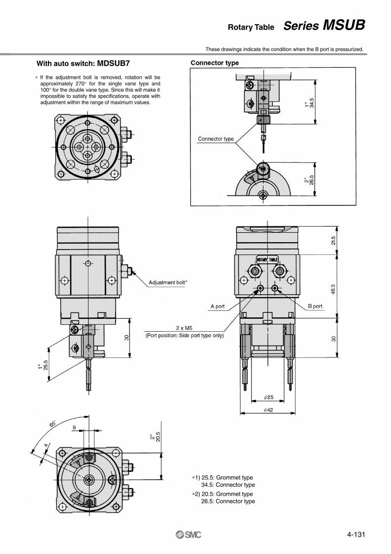
With auto switch: MDSUB7
These drawings indicate the condition when the B port is pressurized.
∗1) 25.5: Grommet type34.5: Connector type
∗2) 20.5: Grommet type26.5: Connector type
∗ If the adjustment bolt is removed, rotation will be approximately 270° for the single vane type and 100° for the double vane type. Since this will make it impossible to satisfy the specifications, operate with adjustment within the range of maximum values.
MSUB7 (Single vane, Double vane)
MSUB7-�S, D
Dimensions These drawings indicate the condition when the B port is pressurized.
The outside drawings show the single vane type, but only the position of the chamfered sections shown in the above drawings differs for single and double vane.
∗ If the adjustment bolt is removed, rotation will be approximately 270° for the single vane type and 100° for the double vane type. Since this will make it impossible to satisfy the specifications, operate with adjustment within the range of maximum values.
Rotary Table Series MSUB
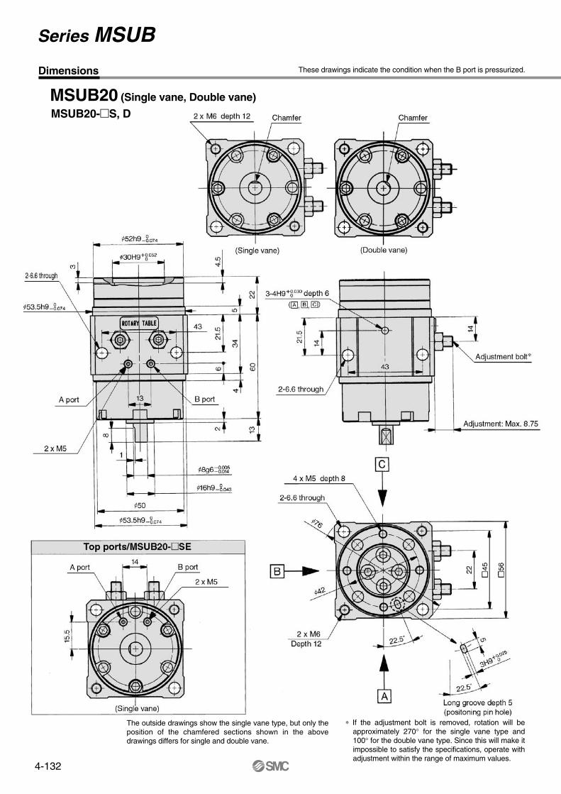
4-132
These drawings indicate the condition when the B port is pressurized.
MSUB20 (Single vane, Double vane)
MSUB20-�S, D
Dimensions
∗ If the adjustment bolt is removed, rotation will be approximately 270° for the single vane type and 100° for the double vane type. Since this will make it impossible to satisfy the specifications, operate with adjustment within the range of maximum values.
The outside drawings show the single vane type, but only the position of the chamfered sections shown in the above drawings differs for single and double vane.
Series MSUB

4-133
With auto switch: MDSUB20
These drawings indicate the condition when the B port is pressurized.
∗ If the adjustment bolt is removed, rotation will be approximately 270° for the single vane type and 100° for the double vane type. Since this will make it impossible to satisfy the specifications, operate with adjustment within the range of maximum values.
∗1) 25.5: Grommet type34.5: Connector type
∗2) 20.5: Grommet type26.5: Connector type
These drawings indicate the condition when the B port is pressurized.
MSUB20 (Single vane, Double vane)
MSUB20-�S, D
Dimensions
∗ If the adjustment bolt is removed, rotation will be approximately 270° for the single vane type and 100° for the double vane type. Since this will make it impossible to satisfy the specifications, operate with adjustment within the range of maximum values.
The outside drawings show the single vane type, but only the position of the chamfered sections shown in the above drawings differs for single and double vane.
Rotary Table Series MSUB

4-134
Internal construction with auto switch
No.12
3
456789101112131415161718192021222324252627282930
DescriptionBody (A)Body (B)
Vane shaft
StopperStopperStopper sealTableStopper lever (D) Stopper lever (S) Lever retainerRing collarBearingBearingBack-up ringScraperO-ringAdjustment boltHexagon nutHexagon socket head cap screwHexagon socket head cap screwHexagon socket head cap screwButton boltRubber capHexagon socket head set screwCoverPlateGasketO-ringO-ringLabel
MaterialAluminum alloyAluminum alloy
Stainless steel (MSUB20: Carbon steel)Carbon steel
ResinStainless steel
NBRAluminum alloyCarbon steelCarbon steelCarbon steelCarbon steel
High carbon chrome bearing steelHigh carbon chrome bearing steel
Stainless steel
NBRNBR
Carbon steelStainless steelStainless steelStainless steelStainless steelCarbon steel
NBRStainless steelAluminum alloy
ResinNBRNBRNBR
NoteLight gray colorLight gray color
Single vaneDouble vaneSingle vaneDouble vane
Light gray color
SE type only
MDSUB 1
MDSUB 3
MDSUB 7
MDSUB20
P211070-1
P211090-1
P211060-1
P211080-1
Auto switch block unit
For MDSUB1, 3 For MDSUB7, 20
Part no.: P211060-8Part no.: P211070-9Part no.: P211070-8
∗ A switch block unit is the assembly required to mount one auto switch on a switch unit.
∗ The plug number 24 is used only when the connection port is type SE.
Single vane: Size 1 Single vane: Sizes 3, 7, 20
Double vane: Size 1 Double vane: Sizes 3, 7, 20
Units are common for both single and double vane.
Parts list
Construction/Parts List
Model Auto switch unit part no.
Left-handedRight-handed Combination left & right-handed
MDSUB1, 3 MDSUB7, 20
The external configuration of the MDSUB1 double vane is different.( )
∗ Auto switches are not included with switch units.
Series MSUB

4-135
Table Positioning Pin Hole Rotation Range and Auto Switch Mounting Position
Applicable series Auto switch model Electrical entry
Grommet (2 wire)
Grommet (2 wire)
Grommet (3 wire)
Grommet (3 wire) PNP
Grommet (2 wire)
Grommet (2 wire)
Grommet (2 wire), Connector (2 wire)
Grommet (3 wire)
Grommet (3 wire) PNP
Grommet (2 wire), Connector (2 wire)
MDSU1
MDSU3
MDSU7
MDSU20
Reedswitch
Solid stateswitch
Reedswitch
Solid stateswitch
D-90, 90A
D-97, 93A
D-S99, S99V
D-S9P, S9PV
D-T99, T99V
D-R73
D-R80
D-S79
D-S7P
D-T79
Applicable auto switches
MSU1, 3Single vane type
90°Double vane type (MSUB only)
90°180°
MSU7, 20Single vane type
90°Double vane type (MSUB only)
90°180°
Model
MDSU1, 3
MDSU7, 20
Rotation range
110°90°
Actuation range
10°
Auto switch rotation and actuation ranges• In drawings that show the rotation range, the arrows on the solid line 90° (180°) indicate the
rotation range of the positioning pin holes on the table surface. When the pin hole is at END1, the END1 switch operates, and when the pin hole is at END2, the END2 switch operates.
• The arrows on the broken line indicate the rotation range of the internal magnet. The rotation range of each switch can be reduced by moving the END1 switch clockwise and the END2 switch counterclockwise.
Internal construction with auto switch
No.12
3
456789101112131415161718192021222324252627282930
DescriptionBody (A)Body (B)
Vane shaft
StopperStopperStopper sealTableStopper lever (D) Stopper lever (S) Lever retainerRing collarBearingBearingBack-up ringScraperO-ringAdjustment boltHexagon nutHexagon socket head cap screwHexagon socket head cap screwHexagon socket head cap screwButton boltRubber capHexagon socket head set screwCoverPlateGasketO-ringO-ringLabel
MaterialAluminum alloyAluminum alloy
Stainless steel (MSUB20: Carbon steel)Carbon steel
ResinStainless steel
NBRAluminum alloyCarbon steelCarbon steelCarbon steelCarbon steel
High carbon chrome bearing steelHigh carbon chrome bearing steel
Stainless steel
NBRNBR
Carbon steelStainless steelStainless steelStainless steelStainless steelCarbon steel
NBRStainless steelAluminum alloy
ResinNBRNBRNBR
NoteLight gray colorLight gray color
Single vaneDouble vaneSingle vaneDouble vane
Light gray color
SE type only
MDSUB 1
MDSUB 3
MDSUB 7
MDSUB20
P211070-1
P211090-1
P211060-1
P211080-1
Auto switch block unit
For MDSUB1, 3 For MDSUB7, 20
Part no.: P211060-8Part no.: P211070-9Part no.: P211070-8
∗ A switch block unit is the assembly required to mount one auto switch on a switch unit.
∗ The plug number 24 is used only when the connection port is type SE.
Single vane: Size 1 Single vane: Sizes 3, 7, 20
Double vane: Size 1 Double vane: Sizes 3, 7, 20
Units are common for both single and double vane.
Parts list
Construction/Parts List
Model Auto switch unit part no.
Left-handedRight-handed Combination left & right-handed
MDSUB1, 3 MDSUB7, 20
The external configuration of the MDSUB1 double vane is different.( )
∗ Auto switches are not included with switch units.
Series MSU
Auto Switch Specifications

4-136
How to change Auto switch Detecting Positions
Auto Switch Units
Auto Switch Mounting Classifications
MDSU1, 3
MDSU7, 20
Left-handedD-992
Right-handedD-991
Left-handedD-2
Right-handedD-1
Model
MDSU 1
MDSU 3
MDSU 7
MDSU20
Unit part number
P211070-1
P211090-1
P211060-1
P211080-1
Auto switch unit part numbers
Auto switch block units
Caution
MDSU1, 3 MDSU7, 20
Left-handedRight-handed Combination left & right-handed
Part no.: P211060-8Part no.: P211070-9Part no.: P211070-8
∗ A switch block unit is the assembly required to mount one switch on a switch unit.
Set screw
MDSU1, 3 MDSU7, 20
∗The magnet lever is included.
Magnet lever
Autoswitchunit
To set a new detection position, slightly loosen the set screw, move the switch to the desired position and retighten the screw. Over-tightening can damage the screw making it impossible to hold the position. Use a tightening torque of about 0.5N⋅m.
Be sure to read before handling.Refer to pages 2.11-2 through 2.11-4 before using auto switches.
Series MSU
Auto Switch Specifications

4-137
1. Adjust the rotation angle within the prescri-bed ranges. (90°±10°, 180°±10°) (±5° at end of rotation)Adjustment outside the prescribed ranges may cause malfunc-tion of the product or failure of switches to operate.
2. Adjust the rotation time within the prescribed values using a speed controller, etc. (0.07 to 0.3s/90°)The product is provided with a fixed throttle and is designed not to operate faster than 0.07s/90°. However, in cases such as a large load inertia, it can exceed the allowable energy causing damage to equipment. (Refer to the model selection procedu-res in this catalog.)Furthermore, adjustment to a speed slower than 0.3s/90° can cause sticking and slipping or stopping of operation.
Mounting
Caution
Maintenance
Caution
Note 1) Note that the rotation angle should not be changed even though the rotary unit has been changed.For maintenance, order units with a part number suitable for the model being used.
Note 2) Due to the integral construction of the MSUB series, the rotary and table units cannot be ordered separately.
Model Unit part no.
P402070-3A
P402070-3B
P402090-3A
P402090-3B
P402060-3A
P402060-3B
P402080-3A
P402080-3B
Rotary unit Model Unit part no.
P402070-2A
P402070-2B
P402090-2A
P402090-2B
P402060-2A
P402060-2B
P402080-2A
P402080-2B
Table unit
<High precision type/MSUA>
MSUA 1-S
MSUA 1-SE
MSUA 3-S
MSUA 3-SE
MSUA 7-S
MSUA 7-SE
MSUA20-S
MSUA20-SE
MSUA 1- 90
MSUA 1-180
MSUA 3- 90
MSUA 3-180
MSUA 7- 90
MSUA 7-180
MSUA20- 90
MSUA20-180
1. Keep the load energy within the product's allowable energy value.Operation with a load kinetic energy exceeding the allowable value can cause human injury and/or damage to equipment or machinery. (Refer to model section procedures in this catalog.)
Selection
Warning
1. When there are load fluctuations, allow a suf-ficient margin in the actuator torque.In case of horizontal mounting (operation with product facing si-deways), malfunction may occur due to load fluctuations.
Caution
In case a rotary unit and table unit are required for maintenance, order with the unit part numbers shown below.
Series MSUSpecific Product Specifications 1Be sure to read before handling.
How to change Auto switch Detecting Positions
Auto Switch Units
Auto Switch Mounting Classifications
MDSU1, 3
MDSU7, 20
Left-handedD-992
Right-handedD-991
Left-handedD-2
Right-handedD-1
Model
MDSU 1
MDSU 3
MDSU 7
MDSU20
Unit part number
P211070-1
P211090-1
P211060-1
P211080-1
Auto switch unit part numbers
Auto switch block units
Caution
MDSU1, 3 MDSU7, 20
Left-handedRight-handed Combination left & right-handed
Part no.: P211060-8Part no.: P211070-9Part no.: P211070-8
∗ A switch block unit is the assembly required to mount one switch on a switch unit.
Set screw
MDSU1, 3 MDSU7, 20
∗The magnet lever is included.
Magnet lever
Autoswitchunit
To set a new detection position, slightly loosen the set screw, move the switch to the desired position and retighten the screw. Over-tightening can damage the screw making it impossible to hold the position. Use a tightening torque of about 0.5N⋅m.
Be sure to read before handling.Refer to pages 2.11-2 through 2.11-4 before using auto switches.

4-138