rotary direct drive manual - motion control systems · commutation techniques. ... the following...
TRANSCRIPT

Gearmotors & Gearheads
Linear & RotaryPositioning Stages
Servo Motors & Drives
Direct Drive Rotary Table
Product Manual

Direct Drive Rotary TableProduct Manual
Rev: 3.2 / 1103P/N: 12197009
Please check www.baysidemotion.com for latest revisions.

I. Introduction 1
II. Packaging 1Uncrating
III. Mechanical Specifications 2
IV. Electrical Specifications 3GeneralMotorRotary Encoder
V. Wiring 6
Appendix
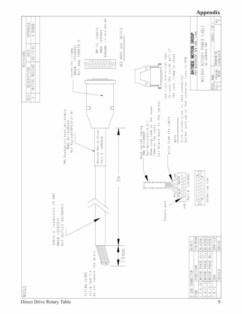
Cable Drawing - 10963067 Rev A 8Cable Drawing - 10963018 Rev A 9Cable Drawing - 10963240 Rev A 10Cable Drawing - 10963241 Rev A 11Cable Drawing - 10963136 Rev A 12
Product Manual
Direct Drive Rotary Table
Table Of Contents
27 Seaview Boulevard * Port Washington, NY 11050 * 516-484-5353 * Fax: 516-484-5496www.baysidemotion.com

Direct Drive Rotary Table 1
Introduction / Packaging
I. Introduction
Thank you for your purchase of the R Series of direct drive rotary tables. The R Series rotary stagesdesigned to meet the most demanding of automation applications. This manual provides installation andmaintenance information for the:
R100D Rotary StagesR150D Rotary StagesR200D Rotary Stages
If there are any questions regarding the set up of your product, please feel free to contact Bayside MotionGroup, at (516)484-5353 for additional support.
II. Packaging
The stage is packaged in a wooden crate/carton with high density foam padding to avoid any damageduring transportation. The assembly is wrapped in plastic to maintain cleanliness and should be handledwith appropriate care.
UncratingAll appropriate stage documentation (including this manual) will be found on top of the stage. The stagecan be easily lifted out of the crate/box and placed on a secure surface.

Direct Drive Rotary Table 2
Mechanical Specifications
Dimensions
MODEL NO. A B C D E F G H J K L M N P
(mm) (mm) (mm) (mm) (mm) (mm) (mm) (mm) Tap (mm) (mm) (mm) (mm) (mm)
R100D 100 100 75 130 50 5 85 20 M5 60 5.5 9.5 25 5
R150D 150 150 78 180 75 7 125 20 M6 95 6.5 11.2 25 5
R200D 200 200 100 230 100 10 160 30 M8 125 8.5 14.0 25 5
Performance Specifications
III. Mechanical Specifications
Model Axial *Perpendicular Continuous Peak MaximumNo. Capacity Capacity Output Output Output
@ Radius Torque Torque Speed (1)
(kgf) (lb) (Nm) (in lb) (Nm) (in lb) (RPM)
R100D 75 165.3 20kgf @ 50mm 0.65 5.75 1.96 17.34 700
R150D 150 330.6 75kgf @ 75mm 4.00 35.4 12.00 106.2 500
R200D 250 551.1 150kgf @ 100mm 6.20 54.80 18.6 164.40 300
*Bearing capacity of a shaft into hole & distance of applied force(1) Maximum output speed based on 300V bus and may be limited by selected drive frequency limitations
Model Radial Axial WobbleNo. Runout Runout @ Axis Inertia Stage Weight
@ øH @ øK of Rotation
(microns) (microns) (arc sec) (gm cm sec2) (oz in sec2) (kg) (lb)
R100D 20 18 60 14.2 0.197 2.2 4.85
R150D 26 23 45 86.4 1.200 5.8 12.79
R200D 36 30 30 338.0 4.695 10.5 23.15

Direct Drive Rotary Table 3
Electrical Specifications
IV. Electrical Specifications
General
The direct drive rotary tables consist of a brushless DC motor, high resolution encoder and loadmounting plate assembled on a single shaft and supported by a single set of precision bearings. Byeliminating any gearing between the motor and load plate, an extremely stiff assembly is created, with nomechanical backlash or hysteresis, resulting in a high servo performance and wide bandwidth capableunit.
The motor can be driven by any three phase brushless DC servo amplifier capable of supplying thevoltage and current shown in the motor specifications.
All I/O signals are available in a single D type connector (see below).
For easy installation, motor power and encoder/Hall cables can be purchased from Bayside MotionGroup. To order cables, please contact Bayside Sales Department at 516-484-5353
R=ROTARYSERIES
DRIVED=Direct Drive
MODEL100150200
OrderNumbering
Example: 1 5 0R D
Cable Options:
See cable drawings in appendix for color codes
Mating Sensor Cable
(1) NOTE: When an external controller is used in a closed loop mode an additional sensor cable, part number 10963136, is required.
Part Number Length Used With10963241_3000 3 meters Flying Leads10963240_3000 3 meters i-Drive10963241_8000 8 meters Flying Leads10963240_8000 8 meters i-Drive10963136
(1)i-Drive / Controller
Part Number Length Used With10963018 3 meters Flying Leads/i-Drive10963067 8 meters Flying Leads/i-Drive
Mating Power Cable

Direct Drive Rotary Table 4
Electrical Specifications
Motor Specifications
Model Voltage Constant Torque Constant Resistance Inductance ThermalNo. KEL-L KTL-L RL-L LL-L Resistance
(V/kRPM) (Nm/amp) (in lb/amp) (ohms@ 25°C) (mH) (°C/W)
R100D 75 0.72 6.37 59.9 50 2.0
R150D 210 2 17.7 11.4 14 2.0
R200D 325 3.1 27.4 10.4 21 2.0
Model Rated Voltage Icont Ipeak Logic Voltage (1) Pole Count
No. (V) (amps) (amps) (V/amp)
R100D 300 0.9 2.72 5 V @ 170 ma 12
R150D 300 2.0 6.0 5 V @ 170 ma 20
R200D 300 2.0 6.0 5 V @ 170 ma 32(2)
Notes:(1) For i-Drive applications, the logic voltage is supplied by thei-drive when using matching sensor cable.
(2) For i-Drive applications, certain parameters would be specially set based on 16 poles dueto 24 pole maximum. Certain user application parameters may require correspondingadjustment due to 32 poles actual.

Direct Drive Rotary Table 5
Electrical Specifications
TemperatureAll motor speed/torque curves are based on 25 deg C ambient with a winding temperature of 155 deg C,at stall. Ambient temperatures above 25 deg C will require derating. Consult Bayside Motion Group at(516) 484-5482, ext. 130 for application assistance.
Circumferential Rotary EncoderThe high resolution encoder has a fixed number of counts per revolution and angular resolution isdetermined per table shown below.
Although to a large extent a function of the closed loop performance of the total system, repeatability of+/-3 counts (+/-6.3 arc sec nominal) is achievable.
CommutationThree commutation signals, derived by digital Hall sensors, are available for Trap Hall or Hall start upcommutation techniques.
Electrical Characteristics of Hall SensorsSupply Voltage 5Vdc + 10% Output Format TTL (Internal pull-up resistors provided), 120 degree spacing
Signal TimingThe following chart shows the timing of the commutation and encoder signals in relation to the motor bemf.
Rotary Motor Signal Timing Rotary Encoder TimingVU-V VV-W VW-U
BEMFWAVEFORMS
ELECTRICALDEGREES
HALL SENSORWAVEFORMS
A
B
I
360+/- 5.5
180 +/- 30
90 +/- 15
90+/- 30 ALL TIMING INELECTRICAL DEGREESSEN3
SEN2
SEN1
0 60 120 180 240 300 360
All timing is for CCW rotation asviewed from the rotary table.CCW
Encoder Data
(1) Post quadrature (includes 10x interpolation and 4x of control)(2) Typical system repeatibility that can be achieved by a closed loop control system.
Model No. R100D R150D R200D
Total Number of counts/rev (1) 473,600 629,760 944,000
Frequency at Max Speed (1) (MHz) 5.5 5.2 4.7
Resolution after x4 (arc sec) 2.73 2.05 1.3728
Repeatability after x4 (arc sec) (2) ± 8.4 ± 6.15 ± 4.1

Direct Drive Rotary Table 6
Wiring
V. WiringSensor Signal Connector
PIN ASSIGNMENTS26-Pin “D” Sub-miniature high density
Pin Number Name Function
1 /ENCA Encoder Channel A
2 ENCA Encoder Channel A
3 /ENCB Encoder Channel B
4 ENCB Encoder Channel B
5 /INDEX Encoder Channel I
6 INDEX Encoder Channel I
7 +5v +5VDC Power Supply
8 GND Ground
9 N/C Spare
10 N/C Spare
11 N/C Spare
12 N/C Spare
13 N/C Spare
14 N/C Spare
15 N/C Spare
16 N/C Spare
17 N/C Spare
18 N/C Spare
19 SEN 1 Hall Sensor 1 (X)
20 SEN 2 Hall Sensor 2 (Y)
21 SEN 3 Hall Sensor 3 (Z)
22 +5V +5VDC Power Supply
23 GND Ground
24 T1 Thermistor
25 T2 Thermistor
26 SHIELD Shield

Direct Drive Rotary Table 7
Wiring
POWER CONNECTORPIN ASSIGNMENTS
15-Pin "D" Sub-miniature
Pin Numbers Name Function
1, 2, 9, 10 PHASE U (X) Motor Power In
3, 4, 11, 12 PHASE V (Y) Motor Power In
5, 6, 13, 14 PHASE W (Z) Motor Power In
7, 8, 15 GND Chassis Ground
Note: Power for Phases are split over multiple pins.

Direct Drive Rotary Table 8
Appendix
Direct Drive Rotary Table 9
Appendix

Direct Drive Rotary Table 10
Appendix

Direct Drive Rotary Table 11
Appendix

Direct Drive Rotary Table 12
Appendix