ross controls · 3-way 2-position valves, ... for ordering the dale cp series manifold valves with...
TRANSCRIPT

ROSS CONTROLS®
dale series ValVes
inline PoPPet ValVes & Manifolds
leaK tight ValVes & Manifolds

www.rosscontrols.com
VALVE
TYPE/FUNCTIONSOLENOID PRESSURE
AVAILABLE INLET PORT SIZES
MA
XIM
UM
F
LO
W C
v MOUNTING
Page
1/4 3/8 1/2 3/4 1 11/4 11/2 2 21/2
INLINE MANIFOLD
CP SERIES
2/2 108 B1.3 - B1.6
3/2 12.3 B1.3 - B1.6
LF SERIES
2/2 62.7 B1.7 - B1.8
CX SERIES for Leak Test Applications
2/2 108 B1.9 - B1.10
3/2 12.3 B1.11
2/2 108 B1.12 - B1.13
3/2 12.3 B1.12 - B1.13
CX SERIES MANIFOLDS for Leak Test Applications
2/2 108 B1.14 - B1.15
3/2 12.3 B1.16
2/2 108 B1.17 - B1.18
3/2 12.3 B1.17 - B1.18
LX SERIES for Leak Test Applications
2/2 62.7 B1.19 - B1.20
2/2 62.7 B1.21
LT SERIES
3/4 2.2 B1.22 - B1.23
Accessories Electrical Connectors, Silencers B1.25
CP Series
LF Series
Internally or externally piloted series for use in standard pressure applications with 30 psi (2 bar) minimum operating pressure.
CX Series LX Series LT Series
Externally piloted only series for use in leak tight, low pressure, vacuum, and process applications.
For use in leak test applications.
B

IMPORTANT NOTE: Please read carefully and thoroughly all of the CAUTIONS, WARNINGS on the inside back cover.
B1.3www.rosscontrols.comOnline VersionRev. 05/16
B1
Dale CP SeriesSolenoid Pilot Controlled Valves
B
3-Way 2-Position Valves, Spring Assisted Air Return
Port SizeModel Number*
Pilot Port ThreadAvg. CV
Weightlb (kg)Internal Pilot Supply
1, 3 2 Normally Closed Normally Open NPT BSPP
1/2 3/8 CP34NB37101** CP44NB37101** 10-32 UNF M5 3.5 1.8 (0.8)
1/2 1/2 CP34NB47101** CP44NB47101** 10-32 UNF M5 3.5 1.8 (0.8)
1 3/4 CP36NB57101** CP46NB57101** 1/8-27 NPT G1/8 12.3 5.3 (2.4)
1 1 CP36NB67101** CP46NB67101** 1/8-27 NPT G1/8 12.3 5.3 (2.4)
* NPT threads. For BSPP threads, replace “N” in the model number with a “D” , e.g., CP34DB37101W.** Insert voltage code: “W” = 24 volts DC; “Z” = 110 volts AC, 120 volts AC; e.g., CP34NB37101W.
1 Normally Open
1/2 Normally Open
1
2
3 1
2
3
1/2 & 1 Normally Closed
13
2
Port Sizes3/8 & 1/2
Port Sizes 3/4 thru 21/2
Port Sizes3/8 & 1/2
Port Sizes3/4 & 1
STANDARD SPECIFICATIONS (for valves on this page):
Accessories ordered separately, refer to page B1.25.
The CP Series valves can be easily field converted to external pilot supply by simply removing existing pipe plug from port X-1, and installing air supply to the X-1 port.
EXTERNAL PILOT SUPPLY CONVERSION:
2-Way 2-Position Valves, Spring Assisted Air Return
Port SizeModel Number*
Pilot Port ThreadAvg. CV
Weightlb (kg)
Internal Pilot Supply
1 2 Normally Closed Normally Open NPT BSPP
1/2 3/8 CP14NB37101** CP24NB37101** 10-32 UNF M5 3.5 1.4 (0.6)
1/2 1/2 CP14NB47101** CP24NB47101** 10-32 UNF M5 3.5 1.4 (0.6)
1 3/4 CP16NB57101** CP26NB57101** 1/8-27 NPT G1/8 12.3 3.5 (1.6)
1 1 CP16NB67101** CP26NB67101** 1/8-27 NPT G1/8 12.3 3.5 (1.6)
11/2 11/4 CP18NB77101** CP28NB77101** 1/8-27 NPT G1/8 44.9 10.0 (4.6)
11/2 11/2 CP18NB87101** CP28NB87101** 1/8-27 NPT G1/8 44.9 10.0 (4.6)
21/2 2 CP10NB97101** CP20NB97101** 1/8-27 NPT G1/8 108 19.5 (8.9)
21/2 21/2 CP10NB07101** CP20NB07101** 1/8-27 NPT G1/8 108 19.5 (8.9)
* NPT threads. For BSPP threads, replace “N” in the model number with a “D” , e.g., CP14DB37101W.** Insert voltage code: “W” = 24 volts DC; “Z” = 110 volts AC, 120 volts AC; e.g., CP14NB37101W.
1/2 thru 21/2Normally Closed
11/2 & 21/2Normally Open
1
2
1
2
1
2
1/2 & 1Normally Open
Construction: Poppet. Mounting Type: Inline.Solenoid Pilot: Rated for continuous duty. Standard Voltages/Power Consumption (each solenoid): 2/2 Valves Port Size 1/2 & 1 and 3/2 Valves Port Size 1/2: 24 volts DC: 1.2 watts on DC. 110 volts AC, 50 Hz: 5.4 VA. 120 volts AC, 60 Hz: 5.0 VA. 2/2 Valves Port Size 11/2 & 21/2 and 3/2 Valves Port Size 1: 24 volts DC; 110 volts AC, 50 Hz; 120 volts AC, 50/60 Hz. 5.8 watts nominal on AC and DC, 6.5 watts maximum on AC and DC.
Ambient Temperature: 40° to 120°F (4° to 50°C).Media Temperature: 40° to 175°F (4° to 80°C).Flow Media: Filtered air. For liquid applications, consult ROSS.Inlet Pressure: 30 to 145 psig (2 to 10 bar).Pilot Pressure: 30 to 145 psig (2 to 10 bar). Must be equal to or greater than inlet pressure. Manual Override: Non-Locking.
2/2 valves: Port Size: 1/2 thru 21/2 (Normally Closed). Port Size: 1/2 & 1 (Normally Open).3/2 valves: Port Size: 1/2 & 1 (Normally Closed). Port Size: 1/2 (Normally Open).

B1.4 © 2016, ROSS CONTROLS®. All Rights Reserved.Online Version
Rev. 05/16
Dale CP SeriesSolenoid Pilot Controlled Valves
0.83 (21.1)
2.85(72.4)2.59
(65.8)2
11.14
(29.0)1.15
(29.2)2.32 (58.8)
0.52(13.3)
2.83 (72.0)3.83 (97.4)
2.83(71.8)
X-11.82
(46.3)
0.92(23.5)
0.73 (18.5)
0.70 (17.8) 1.40(35.5) 2.18 (55.4)
0.41 (10.3)1.01 (25.7)
2.10(53.2)
Ø0.23 (5.8)Ø0.38 (9.8)Ext. Pilot Port
10-32 UNF or M5X0.8
1.31 (33.4)
4.63(117.6)
25.63
(142.9)
1.72(43.7)
1.80(45.6)
3.31 (84.1)4.17 (105.8)
1
3.45(87.6)
X-1
0.70 (17.8)1.63
(41.3)
0.89(22.6)
1.56 (39.6) 2.72 (69.0)
1.00(25.4)
2.77(70.4)
2.61 (66.4)0.32 (8.1) 0.46 (11.7)
Ø0.23 (5.8)Ø0.38 (9.8)
Ext.Pilot Port1/8-27 NPT
or G1/8
2.69(68.3)
8.45(214.6)
X-1
2
1
5.65 (143.4)
6.50 (165.1)
2.38 (60.3)3.75 (95.3)
1.50 (38.1)
Ext. Pilot Port1/8-27 NPT
or G1/8
0.75 (19.1) 2.38 (60.3)
1.25 (31.8)
3.36 (84.4)
1.55 (39.4)
4.55 (115.5)
5.00 (127.0)
1.50 (38.1)
0.28 (7.1)
0.88 (22.2)
Ø0.44 (11.1)Through-Hole
Mounting
6.41 (162.7)
2.56(65.1)1.75
(44.5)
X-11
8.47(215.2)
10.42 (264.8)
3.75(95.3)
3.00 (76.2)5.00 (127.0)
2.50(63.5)
5.50 (139.7)
6.75(171.5)
0.75(19.1) 3.50 (88.9)
5.81(147.7)
1.50(38.1)
0.56(14.3)
0.94 (23.8)
Ext. Pilot Port1/8-27 NPT
or G1/8
Ø0.44 (11.1)Through-Hole Mounting
1.14 (29.0)
4.58 (116.3)3.58 (90.9)
2.83(71.8)
Ø0.23(5.8)Ext. Pilot Port
10-32 UNFor M5-0.8
0.83(21.1)
1.15(29.2)
1.15(29.2)
2.85(72.4)2.59
(65.7)0.52 (13.3)
2
X-11 3
1.25(31.75)
2.93 (74.3) 0.70 (17.8)
1.40 (35.5)3.58 (90.9)
2.10(53.2)
0.41(10.3)
0.38(9.7)
1.15(29.2)
0.74 (18.9)
1.43 (36.3)
4.29 (109.0)
6.19(157.3)
1.72 (43.7)
2.11(53.6)
Ext. Pilot Port1/8-27 NPT
or G1/8
5.00 (127.1)
1 3
4.62 (117.5)
1.16 (29.5) 1.16 (29.5)
X-1
3.45(87.6)2
0.70 (17.8)
0.89(22.6)
1.63 (41.3)
1.56 (39.6)
Ø0.27 (6.8)Ø0.44 (11.3)
0.46(11.7)
2.75(69.9)
0.66(16.8)
Port Size 3/8 & 1/2
Port Size 3/4 & 1
Port Size 11/4 & 11/2
Port Size 2 & 21/2
Port Size 3/8 & 1/2
Port Size 3/4 & 1
B1
3/2 Valves
2/2 Valves
B
Valve Dimensions – inches (mm)

IMPORTANT NOTE: Please read carefully and thoroughly all of the CAUTIONS, WARNINGS on the inside back cover.
B1.5www.rosscontrols.comOnline VersionRev. 05/16
Dale CP SeriesSolenoid Pilot Controlled Valve Manifolds
Valve Manifold Ports 11/4 thru 21/2
Valve Manifold Ports 3/4 & 1
Valve Manifold Ports
3/8 & 1/2
Valve Manifold Ports 3/8 & 1/2
Manifolds can be ordered from two to ten stations. Complete valves-on-manifold assemblies can be ordered to fit your precise requirements.For preassembled manifold valves with the same model number, select the part number from the table below.
For ordering the Dale CP Series manifold valves with different valve functions, please see page B1.24 for manifold configurator.
STANDARD SPECIFICATIONS (for valves on this page):
* NPT threads. For BSPP threads, replace “N” in the model number with a “D”, e.g., CP14DB3711XW.** Insert voltage code: “W” = 24 volts DC; “Z” = 110 volts AC, 120 volts AC; e.g., CP14NB3711XW.X To indicate the number of stations desired (2-10), replace X in the model number with the specific number of stations, e.g., CP14NB37114W, 4 = Number of Stations. Contact ROSS for 1 station valve manifolds or refer to single CX Valve product page.
Valve Manifold Ports 3/4 &1
Accessories ordered separately, refer to page B1.25.
The CP Series valves can be easily field converted to external pilot supply by simply removing existing pipe plug from port X-1, and installing air supply to the X-1 port.
EXTERNAL PILOT SUPPLY CONVERSION:
2-Way 2-Position Valves, Spring Assisted Air Return
Port SizeModel Number*
Pilot Port ThreadAvg. CV
Internal Pilot Supply1 2 Normally Closed Normally Open NPT BSPP
1/2 3/8 CP14NB3711X** CP24NB3711X** 10-32 UNF M5 3.7
1/2 1/2 CP14NB4711X** CP24NB4711X** 10-32 UNF M5 3.7
1 3/4 CP16NB5711X** CP26NB5711X** 1/8-27 NPT G1/8 13.7
1 1 CP16NB6711X** CP26NB6711X** 1/8-27 NPT G1/8 13.7
11/2 11/4 CP18NB7711X** CP28NB7711X** 1/8-27 NPT G1/8 44.9
11/2 11/2 CP18NB8711X** CP28NB8711X** 1/8-27 NPT G1/8 44.9
21/2 2 CP10NB9711X** CP20NB9711X** 1/8-27 NPT G1/8 108
21/2 21/2 CP10NB0711X** CP20NB0711X** 1/8-27 NPT G1/8 108
1/2 & 1Normally Open
1/2 thru 21/2Normally Closed
11/2 & 21/2Normally Open
1
2
1
2
1
2
3-Way 2-Position Valves, Spring Assisted Air Return
Port SizeModel Number*
Pilot Port ThreadAvg. CV
Internal Pilot Supply1, 3 2 Normally Closed Normally Open NPT BSPP
1/2 3/8 CP34NB3711X** CP44NB3711X** 10-32 UNF M5 3.6
1/2 1/2 CP34NB4711X** CP44NB4711X** 10-32 UNF M5 3.6
1 3/4 CP36NB5711X** CP46NB5711X** 1/8-27 NPT G1/8 12.3
1 1 CP36NB6711X** CP46NB6711X** 1/8-27 NPT G1/8 12.3
1 Normally Open
1/2 Normally Open
1
2
3 1
2
31/2 & 1
Normally Closed
13
2
Construction: Poppet. Mounting Type: Inline.Solenoid Pilot: Rated for continuous duty. Standard Voltages/Power Consumption (each solenoid): 2/2 Valves Port Size 1/2 & 1 and 3/2 Valves Port Size 1/2: 24 volts DC: 1.2 watts on DC. 110 volts AC, 50 Hz: 5.4 VA. 120 volts AC, 60 Hz: 5.0 VA. 2/2 Valves Port Size 11/2 & 21/2 and 3/2 Valves Port Size 1: 24 volts DC; 110 volts AC, 50 Hz; 120 volts AC, 50/60 Hz. 5.8 watts nominal on AC and DC, 6.5 watts maximum on AC and DC.
Ambient Temperature: 40° to 120°F (4° to 50°C).Media Temperature: 40° to 175°F (4° to 80°C).Flow Media: Filtered air. For liquid applications, consult ROSS.Inlet Pressure: 30 145 psig (2 to 10 bar).Pilot Pressure: 30 to 145 psig (2 to 10 bar). Must be equal to or greater than inlet pressure. Manual Override: Non-Locking.
2/2 valves: Port Size: 1/2 thru 21/2 (Normally Closed). Port Size: 1/2 & 1 (Normally Open).3/2 valves: Port Size: 1/2 & 1 (Normally Closed). Port Size: 1/2 (Normally Open).
B1
B

B1.6 © 2016, ROSS CONTROLS®. All Rights Reserved.Online Version
Rev. 05/16
Dale CP SeriesSolenoid Pilot Controlled Valve Manifolds
0.52(13.3)
1.15(29.2)
22.85(72.4)
2.93(74.3)
3.58(90.9)
4.58(116.3)
2.13(54.0)
Number of Valves X 1.46 (37.0)
1.14 (29.0)
Ext. Pilot Port10-32 UNFor M5x0.8
0.83(21.1)
1.15 (29.2)
1.15(29.2)
1 3
2 2 2
X1
Ø0.23 (5.8)Ø0.38 (9.8)
2.110(53.6)1 3
X1
Ext. Pilot Port1/8-27 NPT
or G1/8
2 2 2
0.70(17.8)
2.75(69.9)
4.29(109.0)
5.00(127.1)
Number of Valves X 2.25 (57.2)
2
0.89(22.6)
4.63(117.5)
6.20(157.5)
2.75(69.9)
1.72 (43.7)
1.56(39.6)
1.16(29.5)
1.16(29.4)
Ø0.27 (6.8)Ø0.44 (11.3)
1.55(39.4)
3.36(85.4)
4.55(115.6)
5.65(143.4)
6.50(165.1)
8.45(214.6)
1.25(31.8)
4.25(108.0)
2.38(60.3)
2.69(68.3)
3.75 (95.3)
1.50(38.1)
1
2
X1
Number of Valves X 3.75 (95.3)
2 2 2
Ø0.44 (11.1)
Ext. Pilot Port1/8-27 NPTor G1/8
0.75(19.1)
2.50(63.5)
8.47(215.2)
10.42(264.8)
0.75(19.1)
6.00(152.4)
5.5(139.7)
6.40(162.7)
3.00(76.2) 5.00
(127.0)
3.75(95.3)
Number of Valves X 5.00 (127.0)
Ext.Pilot Port1/8-27 NPTor G1/8
2 2 2 2
X11
0.94(23.8)
Ø0.39 (9.9)
0.75(19.1)
6.00(152.4)Number of Valves X 5.00 (127.0)
0.89(22.6)
22.61
(66.4)3.31
(84.1)
4.17(105.8)1.15
(29.2)
2.75(69.9)
Number of Valves X 2.25 (57.2)
4.63(117.5)
5.63(142.9)
2 2 2
1.56(39.6)
2.72 (69.0)
1.72(43.7)
1.80(45.6)
Ext. Pilot Port1/8-27 NPT
or G1/8
1X1
0.70(17.8)
Ø0.23 (5.8)Ø0.38 (9.8)
0.52 (13.3)2
2.85(72.4)
1.42(36.0) 2.18
(55.4)
3.83(97.4)
2.83(72.0)
2.13(54.0)
Number Of Valves X 1.46 (37.1)
0.83(21.1)
1
1.14(29.0)
2.32 (58.8)
Ext. Pilot Port10-32 UNFor M5x0.8
2 2 2
X11.15
(29.2) 0.70 (17.8)
Ø0.21 (5.3)Ø0.38 (9.8)
Port Size 3/8 & 1/2
Port Size 3/4 & 1
Port Size 11/4 & 11/2
Port Size 2 & 21/2
Port Size 3/8 & 1/2
Port Size 3/4 & 1
B1
3/2 Valves
2/2 Valves
B
Dimensions – inches (mm)

IMPORTANT NOTE: Please read carefully and thoroughly all of the CAUTIONS, WARNINGS on the inside back cover.
B1.7www.rosscontrols.comOnline VersionRev. 05/16
Dale LF SeriesSolenoid Pilot Controlled Valves
Ports 3/8 thru 1
Ports 11/4 thru 21/2
Construction: Poppet. Mounting Type: Inline. Solenoid Pilot: Rated for continuous duty. Standard Voltages/Power Consumption (each solenoid): Port Size 3/8 thru 1: 24 volts DC: 1.2 watts on DC. 110 volts AC, 50 Hz: 5.4 VA. 120 volts AC, 60 Hz: 5.0 VA. Port Size 11/4 thru 21/2: 24 volts DC; 110 volts AC, 50 Hz; 120 volts AC, 50/60 Hz. 5.8 watts nominal on AC and DC, 6.5 watts maximum on AC and DC.
Ambient Temperature: 40° to 120°F (4° to 50°C).Media Temperature: 40° to 175°F (4° to 80°C).Flow Media: Filtered air. For liquid applications, consult ROSS.Inlet Pressure: 30 to 145 psig (2 to 10 bar).Pilot Pressure: 30 to 145 psig (2 to 10 bar). Must be equal to or greater than inlet pressure. Manual Override: Non-Locking.Port Size: 3/8 thru 21/2 (Normally Closed). Port Size: 3/8 thru 1 (Normally Open).
STANDARD SPECIFICATIONS (for valves on this page):
Accessories ordered separately, refer to page B1.25.
2-Way 2-Position Valves, Spring Assisted Air Return
Port SizeModel Number*
Pilot Port Thread Avg. CV
Weightlb (kg)
Internal Pilot Supply
1 2 Normally Closed Normally Open NPT BSPP
3/8 3/8 LF13NB37101** LF23NB37101** 1/8-27 NPT G1/8 3.6 1.5 (0.7)
1/2 1/2 LF14NB47101** LF24NB47101** 1/8-27 NPT G1/8 3.6 1.5 (0.7)
3/4 3/4 LF15NB57101** LF25NB57101** 1/8-27 NPT G1/8 12.2 3.5 (1.6)
1 1 LF16NB67101** LF26NB67101** 1/8-27 NPT G1/8 12.2 3.5 (1.6)
11/4 11/4 LF17NB77101** LF27NB77101** 1/8-27 NPT G1/8 36.1 9.3 (4.2)
11/2 11/2 LF18NB87101** LF28NB87101** 1/8-27 NPT G1/8 36.1 9.3 (4.2)
2 2 LF19NB97101** LF29NB97101** 1/8-27 NPT G1/8 62.7 19.3 (8.8)
21/2 21/2 LF10NB07101** LF20NB07101** 1/8-27 NPT G1/8 62.7 19.3 (8.8)
* NPT threads. For BSPP threads, replace “N” in the model number with a “D”, e.g., LF13DB37101W.** Insert voltage code: “W” = 24 volts DC; “Z” = 110 volts AC, 120 volts AC; e.g., LF13NB37101W.
1
2
11/4 thru 21/2 Normally OpenNormally Closed
1
2
3/8 thru 1Normally Open
1
2
The LF & LX Series provides superior performance over a diaphragm valve with a rugged poppet design, bi-directional flow and high cycle life.
The LF & LX Series provides superior performance over a ball valve with solenoid actuation, shifting speed, cycle life, and most important, a cost effective alternative.
Diaphragm Valve
Ball Valve
Improved
Performance
Cost
Effective
The LF Series valves can be easily field converted to external pilot supply by simply removing existing pipe plug from port X-1, and installing air supply to the X-1 port.
EXTERNAL PILOT SUPPLY CONVERSION:
B1
B

B1.8 © 2016, ROSS CONTROLS®. All Rights Reserved.Online Version
Rev. 05/16
Dale LF SeriesSolenoid Pilot Controlled Valves
3.12 (79.3)
3.06(77.7)
4.78(121.3)
0.72(18.3)
FLOW
2.94(74.7)
3.38(85.7)
1.87(47.6)
0.72(18.3)
SpeedControlX-1
1.45(36.9)
Ext. Pilot Port1/8-27 NPT
or G1/8 2.42 (61.4)
1.87(47.6)
Ø 0.21 (5.3)Through-Hole
Mounting
4.12 (104.7)
4.52(114.9)
4.11(104.3)
6.34(161.0)
FLOW
1.09(27.8)
4.94(125.4)
1.09(27.8)
2.50(63.5)
X-1SpeedControl
2.50(63.5)
Ext. Pilot Port1/8-27 NPT
or G1/8
Ø 0.25 (8.6)Through-Hole
Mounting
3.25 (82.5)
2.05(52.0)
5.50 (139.7)
6.52(165.7)
9.09(230.8)
6.15(156.2)
FLOW
X-1
1.50(38.1)
7.20(182.8)
1.50(38.1)
3.75 (95.3)
Speed Control
3.75(95.3)
Ext Pilot Port1/8-27 NPT
or G1/8
1.19(30.1)
Ø0.33 (8.3) Through-Hole
Mounting
3.20(81.3)
10.74(272.9)
8.11(205.9)
7.50 (190.5)
FLOW
1.75(44.5)
7.79(198.0)
8.86(224.9) 5.00 (127.0)
1.75(44.5)
X-1 SpeedControl
5.00(127.0)
Ext. Pilot Port1/8-27 NPT
or G1/8
1.09(27.8)
Ø0.34 (8.7) Through-Hole
Mounting
4.36(110.1)
Port Size 3/8 & 1/2
Port Size 3/4 & 1
Port Size 11/4 & 11/2
Port Size 2 & 21/2
B1
B
Valve Dimensions – inches (mm)

IMPORTANT NOTE: Please read carefully and thoroughly all of the CAUTIONS, WARNINGS on the inside back cover.
B1.9www.rosscontrols.comOnline VersionRev. 05/16
Dale CX SeriesSolenoid Pilot Controlled Valvesfor Leak Tight Applications
Port Sizes3/8 & 1/2
Port Sizes 1/4, 3/4 thru 21/2
STANDARD SPECIFICATIONS (for valves on this page):
Accessories ordered separately, refer to page B1.25.
2-Way 2-Position Valves, Spring Assisted Air Return
Port SizeModel Number*
Pilot Port Thread Avg. CV
Weightlb (kg)
External Pilot Supply
1 2 Normally Closed Normally Open NPT BSPP
1/4 1/4 CX12NB27501** CX22NB27501** 10-32 UNF M5 0.9 1.3 (0.6)
1/2 3/8 CX14NB37501** CX24NB37501** 10-32 UNF M5 3.5 1.4 (0.6)
1/2 1/2 CX14NB47501** CX24NB47501** 10-32 UNF M5 3.5 1.4 (0.6)
1 3/4 CX16NB57501** CX26NB57501** 1/8-27 NPT G1/8 12.3 3.5 (1.6)
1 1 CX16NB67501** CX26NB67501** 1/8-27 NPT G1/8 12.3 3.5 (1.6)
11/2 11/4 CX18NB77501** CX28NB77501** 1/8-27 NPT G1/8 44.9 10.0 (4.6)
11/2 11/2 CX18NB87501** CX28NB87501** 1/8-27 NPT G1/8 44.9 10.0 (4.6)
21/2 2 CX10NB97501** CX20NB97501** 1/8-27 NPT G1/8 108 19.5 (8.9)
21/2 21/2 CX10NB07501** CX20NB07501** 1/8-27 NPT G1/8 108 19.5 (8.9)
* NPT threads. For BSPP threads, replace “N” in the model number with a “D”, e.g., CX12DB27501W.** Insert voltage code: “W” = 24 volts DC; “Z” = 110 volts AC, 120 volts AC; e.g., CX12NB27501W.
1/4 thru 21/2Normally Closed
11/2 & 21/2Normally Open
1
2
1
2
1
2
1/4 thru 1Normally Open
Construction: Poppet. Mounting Type: Inline.Solenoid Pilot: Rated for continuous duty. Standard Voltages/Power Consumption (each solenoid): Port Size 1/4 thru 1: 24 volts DC: 1.2 watts on DC. 110 volts AC, 50 Hz: 5.4 VA. 120 volts AC, 60 Hz: 5.0 VA. Port Size 11/4 thru 21/2: 24 volts DC; 110 volts AC, 50 Hz; 120 volts AC, 50/60 Hz. 5.8 watts nominal on AC and DC, 6.5 watts maximum on AC and DC.Ambient Temperature: 40° to 120°F (4° to 50°C).
Media Temperature: 40° to 175°F (4° to 80°C).Flow Media: Filtered air. For liquid applications, consult ROSS.Inlet Pressure: Port Size 1/4: Vacuum to 250 psig (vacuum to 17.2 bar).Port Size 1/2 thru 21/2: Vacuum to 145 psig (vacuum to 10 bar).Pilot Pressure: Port Size 1/4: 70 to 145 psig (5 to 10 bar).Port Size 1/2 thru 21/2: 30 to 145 psig (2 to 10 bar). Must be equal to or greater than inlet pressure. Manual Override: Non-Locking. Port Size: 1/4 thru 21/2 (Normally Closed). Port Size: 1/4 thru 1 (Normally Open).
Features & Benefits:
Compact Manifold Design – Eliminating pipingHigh Flow – CP Series port sizes from 3/8” to 2-1/2”Consistent Shifting – Dual piston provides smooth, consistent shiftingBi-Directional Flow – Allows pressure or vacuum on any port at any timeReduced Downtime – Poppet cartridge rebuilds completed in minutesLife Test – Tested to 20 million cycles
B1
B

B1.10 © 2016, ROSS CONTROLS®. All Rights Reserved.Online Version
Rev. 05/16
Dale CX SeriesSolenoid Pilot Controlled Valvesfor Leak Tight Applications
0.83 (21.1)
2.85(72.4)2.59
(65.8)2
11.14
(29.0)1.15
(29.2)2.32 (58.8)
0.52(13.3)
2.83 (72.0)3.83 (97.4)
2.83(71.8)
X-11.82
(46.3)
0.92(23.5)
0.73 (18.5)
0.70 (17.8) 1.40(35.5) 2.18 (55.4)
0.41 (10.3)1.01 (25.7)
2.10(53.2)
Ø0.23 (5.8)Ø0.38 (9.8)Ext. Pilot Port
10-32 UNF or M5X0.8
1.31 (33.4)
4.63(117.6)
25.63
(142.9)
1.72(43.7)
1.80(45.6)
3.31 (84.1)4.17 (105.8)
1
3.45(87.6)
X-1
0.70 (17.8)1.63
(41.3)
0.89(22.6)
1.56 (39.6) 2.72 (69.0)
1.00(25.4)
2.77(70.4)
2.61 (66.4)0.32 (8.1) 0.46 (11.7)
Ø0.23 (5.8)Ø0.38 (9.8)
Ext.Pilot Port1/8-27 NPT
or G1/8
2.69(68.3)
8.45(214.6)
X-1
2
1
5.65 (143.4)
6.50 (165.1)
2.38 (60.3)3.75 (95.3)
1.50 (38.1)
Ext. Pilot Port1/8-27 NPT
or G1/8
0.75 (19.1) 2.38 (60.3)
1.25 (31.8)
3.36 (84.4)
1.55 (39.4)
4.55 (115.5)
5.00 (127.0)
1.50 (38.1)
0.28 (7.1)
0.88 (22.2)
Ø0.44 (11.1)Through-Hole
Mounting
6.41 (162.7)
2.56(65.1)1.75
(44.5)
X-11
8.47(215.2)
10.42 (264.8)
3.75(95.3)
3.00 (76.2)5.00 (127.0)
2.50(63.5)
5.50 (139.7)
6.75(171.5)
0.75(19.1) 3.50 (88.9)
5.81(147.7)
1.50(38.1)
0.56(14.3)
0.94 (23.8)
Ext. Pilot Port1/8-27 NPT
or G1/8
Ø0.44 (11.1)Through-Hole Mounting
Port Size 3/8 & 1/2
Port Size 3/4 & 1
Port Size 11/4 & 11/2
Port Size 2 & 21/2
Port Size 1/4
2
1
Ext. Pilot Port10-32 UNF or M5X0.8 2.33 (59.2)
4.45(113.4)
3.07(77.9)
2.70 (68.6)
X-11.20
(30.4)1.89 (48.0)
0.55(14.1)
1.30(33.0)
0.47(11.9)
Ø0.19 (4.8)Ø0.33 (8.4)
1.10(27.8)
0.64 (16.3)
0.92(23.3)
B1
B
Valve Dimensions – inches (mm)

IMPORTANT NOTE: Please read carefully and thoroughly all of the CAUTIONS, WARNINGS on the inside back cover.
B1.11www.rosscontrols.comOnline VersionRev. 05/16
Dale CX SeriesSolenoid Pilot Controlled Valvesfor Leak Tight Applications
1.14 (29.0)
4.58 (116.3)3.58 (90.9)
2.83(71.8)
Ø0.23(5.8)Ext. Pilot Port
10-32 UNFor M5-0.8
0.83(21.1)
1.15(29.2)
1.15(29.2)
2.85(72.4)2.59
(65.7)0.52 (13.3)
2
X-11 3
1.25(31.75)
2.93 (74.3) 0.70 (17.8)
1.40 (35.5)3.58 (90.9)
2.10(53.2)
0.41(10.3)
0.38(9.7)
1.15(29.2)
0.74 (18.9)
1.43 (36.3)
4.29 (109.0)
6.19(157.3)
1.72 (43.7)
2.11(53.6)
Ext. Pilot Port1/8-27 NPT
or G1/8
5.00 (127.1)
1 3
4.62 (117.5)
1.16 (29.5) 1.16 (29.5)
X-1
3.45(87.6)2
0.70 (17.8)
0.89(22.6)
1.63 (41.3)
1.56 (39.6)
Ø0.27 (6.8)Ø0.44 (11.3)
0.46(11.7)
2.75(69.9)
0.66(16.8)
Port Size 3/8 & 1/2
Port Size 3/4 & 1
STANDARD SPECIFICATIONS (for valves on this page):
Accessories ordered separately, refer to page B1.25.
Construction: Poppet. Mounting Type: Inline.Solenoid Pilot: Rated for continuous duty. Standard Voltages/Power Consumption (each solenoid): Port Size 1/2: 24 volts DC: 1.2 watts on DC. 110 volts AC, 50 Hz: 5.4 VA. 120 volts AC, 60 Hz: 5.0 VA. Port Size 1: 24 volts DC; 110 volts AC, 50 Hz; 120 volts AC, 50/60 Hz.5.8 watts nominal on AC and DC, 6.5 watts maximum on AC and DC.
Ambient Temperature: 40° to 120°F (4° to 50°C).Media Temperature: 40° to 175°F (4° to 80°C).Flow Media: Filtered air. For liquid applications, consult ROSS.Inlet Pressure: Vacuum to 145 psig (vacuum to 10 bar).Pilot Pressure: 50 to 145 psig (3.4 to 10 bar). Must be equal to or greater than inlet pressure.Manual Override: Non-Locking.
Port Size: 1/2 & 1 (Normally Closed). Port Size: 1/2 (Normally Open).
Port Sizes3/8 & 1/2
Port Sizes3/4 & 1
3-Way 2-Position Valves, Spring Assisted Air Return
Port SizeModel Number*
Pilot Port Thread Avg. CV
Weightlb (kg)
External Pilot Supply
1, 3 2 Normally Closed Normally Open NPT BSPP
1/2 3/8 CX34NB37501** CX44NB37501** 10-32 UNF M5 3.5 1.8 (0.8)
1/2 1/2 CX34NB47501** CX44NB47501** 10-32 UNF M5 3.5 1.8 (0.8)
1 3/4 CX36NB57501** CX46NB57501** 1/8-27 NPT G1/8 12.3 5.3 (2.4)
1 1 CX36NB67501** CX46NB67501** 1/8-27 NPT G1/8 12.3 5.3 (2.4)
* NPT threads. For BSPP threads, replace “N” in the model number with a “D”, e.g., CX34DB37501W.** Insert voltage code: “W” = 24 volts DC; “Z” = 110 volts AC, 120 volts AC; e.g., CX34NB37501W.
1Normally Open
1/2 Normally Open
1
2
3 1
2
3
1/2 & 1Normally Closed
13
2
B1
B
Valve Dimensions – inches (mm)

B1.12 © 2016, ROSS CONTROLS®. All Rights Reserved.
IMPORTANT NOTE: Please read carefully and thoroughly all of the CAUTIONS, WARNINGS on the inside back cover.
Online VersionRev. 05/16
Dale CX Series
Pressure Controlled Valvesfor Leak Tight Applications
3-Way 2-Position Valves, Spring Assisted Air ReturnPort Size Model Number* Pilot Port Thread
Avg. CV
Weightlb (kg)
1, 3 2 Normally Closed NPT BSPP
1/2 3/8 CX34NB35501 10-32 UNF M5 3.5 1.4 (0.6)
1/2 1/2 CX34NB45501 10-32 UNF M5 3.5 1.4 (0.6)
1 3/4 CX36NB55501 1/8-27 NPT G1/8 12.3 3.5 (1.6)
1 1 CX36NB65501 1/8-27 NPT G1/8 12.3 3.5 (1.6)
* NPT threads. For BSPP threads, replace “N” in the model number with a “D”, e.g., CX34DB35501.
2-Way 2-Position Valves, Spring Assisted Air ReturnPort Size
Model Number* Pilot Port ThreadAvg. CV
Weightlb (kg)
1 2 Normally Closed NPT BSPP
1/2 3/8 CX14NB35501 10-32 UNF M5 3.5 1.4 (0.6)
1/2 1/2 CX14NB45501 10-32 UNF M5 3.5 1.4 (0.6)
1 3/4 CX16NB55501 1/8-27 NPT G1/8 12.3 3.5 (1.6)
1 1 CX16NB65501 1/8-27 NPT G1/8 12.3 3.5 (1.6)
11/2 11/4 CX18NB75501 1/8-27 NPT G1/8 44.9 10.0 (4.6)
11/2 11/2 CX18NB85501 1/8-27 NPT G1/8 44.9 10.0 (4.6)
21/2 2 CX10NB95501 1/8-27 NPT G1/8 108 19.5 (8.9)
21/2 21/2 CX10NB05501 1/8-27 NPT G1/8 108 19.5 (8.9)
* NPT threads. For BSPP threads, replace “N” in the model number with a “D”, e.g., CX34DB35501.
1
2
3
2
1
Construction: Poppet. Mounting Type: Inline.Ambient Temperature: 40° to 120°F (4° to 50°C).Media Temperature: 40° to 175°F (4° to 80°C).Flow Media: Filtered air. For liquid applications, consult ROSS.Inlet Pressure: Vacuum to 250 psig (17.2 bar).
Pilot Pressure: 2/2 valves: 30 to 250 psig (2 to 17.2 bar). Must be equal to or greater
than inlet pressure.3/2 valves: 50 to 250 psig (3.4 to 17.2 bar). Must be equal to or
greater than inlet pressure.
STANDARD SPECIFICATIONS (for valves on this page):
Note: The Dale Series pressure controlled valves require both an external pilot supply and a control signal to operate the valve. When a pressure control signal is applied the valve shifts to the open position.
Pressure Control Signal
External Pilot Supply
1 3
X-1
Accessories ordered separately, refer to page B1.25.
Port Sizes3/8 & 1/2
Port Sizes 3/4 thru 21/2
B1
B

B1.13www.rosscontrols.comOnline VersionRev. 05/16
Dale CX SeriesPressure Controlled Valvesfor Leak Tight Applications
2.56(65.1)1.75
(44.5)
X-11
2
Ext. Pilot Port1/8-27 NPTor G1/8
8.47(215.2)
9.62 (244.4)
3.75(95.3)
3.00 (76.2)5.00 (127.0)
2.50(63.5)
5.50 (139.7)
6.75(171.5)
0.75(19.1) 3.50 (88.9)
Pilot Port 1/8-27 NPT or G1/8
5.81(147.7)
1.50(38.1)
0.56 (14.3) 0.94 (23.8)Ø 0.44 (11.1)
3.36 (85.4)
2.69(68.3)
7.68(194.3)
X-1
2
1
1.55 (39.4)
4.55 (115.5)
6.50 (165.1)
3.75 (59.3)
1.50 (38.1)
Ext. Pilot Port1/8-27 NPT
or G1/8
5.00 (127.0)
0.75(19.1) 2.38 (60.3)
1.25 (31.8)
1.50 (38.1)
0.28 (7.1)
0.88 (22.2)2.38 (60.3)
Pilot Port1/8-27 NPT
or G1/8
Ø 0.44 (11.1)Thru Hole Mounting
3.94 (100.0)3.58 (90.9)
2.83(71.8)
1.15(29.2)
1.14 (29.0)
Ext. Pilot Port10-32 UNFor M5-0.8
0.83(21.1)
1.15(29.2) 2.93 (74.3)
2.10(53.2)
0.41(10.3)
0.38(9.7)
1.15(29.2)
0.74 (18.9)
2.85(72.4)2.59
(65.7)0.52 (13.3)
2
1.25(31.75)
0.70 (17.8)1.40 (35.5)
3.58 (90.9)1.43 (36.3)
X-11 3
Ø0.23 (5.8)Ø0.38 (9.8)
4.29 (109.0)
6.19(157.3)
1.72 (43.7)
2.11(53.6)
Ext. Pilot Port1/8-27 NPT
or G1/8
5.00 (127.1)
1 3
4.62 (117.5)
1.16 (29.5) 1.16 (29.5)
X-1
3.45(87.6)2
0.70 (17.8)
0.89(22.6)
1.63 (41.3)
1.56 (39.6)
Ø0.27 (6.8)Ø0.44 (11.3)
0.46(11.7)
2.75(69.9)
0.66(16.8)
Ø0.23 (5.8)Ø0.38 (9.8)
2.85(72.4)
0.73 (18.5)
0.52(13.3)
2.18 (55.4)
2.83 (72.0)3.19 (81.1)
2.83(71.8)
20.83
(21.1)11.14
(29.0)1.15
(29.2)2.32 (58.8)
Ext. Pilot Port10-32 UNFor M5X0.8
0.70(17.8)
1.90(48.3)
1.40(35.5)
2.10(53.2) 0.38
(9.7)
0.41 (10.3)1.01 (25.7)
X-1
1.82(46.3)
0.92(23.5)
Pilot Port10-32 UNFor M5X0.8
Ø0.23 (5.8)Ø0.38 (9.8)
1.31 (33.4)
2.61 (66.4)
4.63(117.5)
24.94(125.5)
1.56(39.6) 2.72 (69.0)
1.72(43.7)
1.80(45.6)
Ext. Pilot Port1/8-27 NPT
or G1/83.31 (84.1)
3.53 (89.5)
1
3.45(87.6)
X-1
0.70(17.8)
Pilot Port10-32 UNF or M5x0.8
2.77(70.4)
0.32(8.1)
1.00(25.4)
0.46 (11.7)1.63(41.3)
0.89(22.6)
Port Size 3/8 & 1/2
Port Size 3/4 & 1
Port Size 11/4 & 11/2
Port Size 2 & 21/2
Port Size 3/8 & 1/2
Port Size 3/4 & 1
3/2 Valves
2/2 Valves
B1
B
Valve Dimensions – inches (mm)

B1.14 © 2016, ROSS CONTROLS®. All Rights Reserved.
IMPORTANT NOTE: Please read carefully and thoroughly all of the CAUTIONS, WARNINGS on the inside back cover.
Online VersionRev. 05/16
Dale CX SeriesSolenoid Pilot Controlled Valve Manifoldsfor Leak Tight Applications
Manifolds can be ordered from two to ten stations. Complete valves-on-manifold assemblies can be ordered to fit your precise requirements.For preassembled manifold valves with the same model number, select the part number from the table below.
For ordering the Dale CX Series manifold valves with different valve functions, please see page B1.24 for manifold configurator.
STANDARD SPECIFICATIONS (for valves on this page):
* NPT threads. For BSPP threads, replace “N” in the model number with a “D”, e.g., CX12DB2751XW.** Insert voltage code: “W” = 24 volts DC; “Z” = 110 volts AC, 120 volts AC; e.g.,CX12NB2751XW.X To indicate the number of stations desired, replace X in the model number with the specific number of stations, e.g., CX12NB27514W, 4 = Number of Stations.
Accessories ordered separately, refer to page B1.25.
1
2
1
2
1
2
1/4 thru 21/2Normally Closed
11/2 & 21/2Normally Open
1/4 thru 1Normally Open
Construction: Poppet. Mounting Type: Inline.Solenoid Pilot: Rated for continuous duty. Standard Voltages/Power Consumption (each solenoid): Port Size 1/4 thru 1: 24 volts DC: 1.2 watts on DC. 110 volts AC, 50 Hz: 5.4 VA. 120 volts AC, 60 Hz: 5.0 VA. Port Size 11/4 thru 21/2: 24 volts DC; 110 volts AC, 50 Hz; 120 volts AC, 50/60 Hz.5.8 watts nominal on AC and DC, 6.5 watts maximum on AC and DC.Ambient Temperature: 40° to 120°F (4° to 50°C).Media Temperature: 40° to 175°F (4° to 80°C).
Flow Media: Filtered air. For liquid applications, consult ROSS.Inlet Pressure: Port Size 1/4: Vacuum to 250 psig (vacuum to 17.2 bar).Port Size 1/2 thru 21/2: Vacuum to 145 psig (vacuum to 10 bar).Pilot Pressure: Port Size 1/4: 70 to 145 psig (5 to 10 bar).Port Size 1/2 thru 21/2: 30 to 145 psig (2 to 10 bar). Must be equal to or greater than inlet pressure. Manual Override: Non-Locking. Port Size: 1/4 thru 21/2 (Normally Closed).
Port Size: 1/4 thru 1 (Normally Open).
Valve Manifold Ports 1/4, 11/4 thru 21/2
Valve Manifold Ports 3/8 & 1/2
Valve Manifold Ports 3/4 &1
2-Way 2-Position Valves, Spring Assisted Air Return
Port SizeModel Number*
Pilot Port ThreadAvg. CVExternal Pilot Supply
1 2 Normally Closed Normally Open NPT BSPP
1/4 1/4 CX12NB2751X** CX22NB2751X** 10-32 UNF M5 0.9
1/2 3/8 CX14NB3751X** CX24NB3751X** 10-32 UNF M5 3.5
1/2 1/2 CX14NB4751X** CX24NB4751X** 10-32 UNF M5 3.5
1 3/4 CX16NB5751X** CX26NB5751X** 1/8-27 NPT G1/8 12.3
1 1 CX16NB6751X** CX26NB6751X** 1/8-27 NPT G1/8 12.3
11/2 11/4 CX18NB7751X** CX28NB7751X** 1/8-27 NPT G1/8 44.9
11/2 11/2 CX18NB8751X** CX28NB8751X** 1/8-27 NPT G1/8 44.9
21/2 2 CX10NB9751X** CX20NB9751X** 1/8-27 NPT G1/8 108
21/2 21/2 CX10NB0751X** CX20NB0751X** 1/8-27 NPT G1/8 108
Features & Benefits:Compact Manifold Design – Eliminating pipingHigh Flow – CP Series port sizes from 3/8” to 2-1/2”Consistent Shifting – Dual piston provides smooth, consistent shiftingBi-Directional Flow – Allows pressure or vacuum on any port at any timeReduced Downtime – Poppet cartridge rebuilds completed in minutesLife Test – Tested to 20 million cycles
B1
B

B1.15www.rosscontrols.comOnline VersionRev. 05/16
Dale CX SeriesSolenoid Pilot Controlled Valve Manifoldsfor Leak Tight Applications
1.55(39.4)
3.36(85.4)
4.55(115.6)
5.65(143.4)
6.50(165.1)
8.45(214.6)
1.25(31.8)
4.25(108.0)
2.38(60.3)
2.69(68.3)
3.75 (95.3)
1.50(38.1)
1
2
X1
Number of Valves X 3.75 (95.3)
2 2 2
Ø0.44 (11.1)
Ext. Pilot Port1/8-27 NPTor G1/8
0.75(19.1)
2.50(63.5)
8.47(215.2)
10.42(264.8)
0.75(19.1)
6.00(152.4)
5.5(139.7)
6.40(162.7)
3.00(76.2) 5.00
(127.0)
3.75(95.3)
Number of Valves X 5.00 (127.0)
Ext.Pilot Port1/8-27 NPTor G1/8
2 2 2 2
X11
0.94(23.8)
Ø0.39 (9.9)
0.75(19.1)
6.00(152.4)Number of Valves X 5.00 (127.0)
0.89(22.6)
22.61
(66.4)3.31
(84.1)
4.17(105.8)1.15
(29.2)
2.75(69.9)
Number of Valves X 2.25 (57.2)
4.63(117.5)
5.63(142.9)
2 2 2
1.56(39.6)
2.72 (69.0)
1.72(43.7)
1.80(45.6)
Ext. Pilot Port1/8-27 NPT
or G1/8
1X1
0.70(17.8)
Ø0.23 (5.8)Ø0.38 (9.8)
0.52 (13.3)2
2.85(72.4)
1.42(36.0) 2.18
(55.4)
3.83(97.4)
2.83(72.0)
2.13(54.0)
Number Of Valves X 1.46 (37.1)
0.83(21.1)
1
1.14(29.0)
2.32 (58.8)
Ext. Pilot Port10-32 UNFor M5x0.8
2 2 2
X11.15
(29.2) 0.70 (17.8)
Ø0.21 (5.3)Ø0.38 (9.8)
Port Size 3/8 & 1/2
Port Size 3/4 & 1
Port Size 11/4 & 11/2
Port Size 2 & 21/2
Port Size 1/4
1
Ext. Pilot Port10-32 UNF or M5X0.8
2.33 (59.2)
4.45(113.4)
3.07(77.9)
X-11.20
(30.4)1.89 (48.0) 1.30 (33.0)
0.47(11.9)
Ø0.19 (4.8)Ø0.33 (8.4)
0.64(16.3)
0.92(23.3)
Number Of Valves X 1.80 (45.7)
0.70 (17.8)
2.18(55.4)
2.83(72.0)
2.70(68.6)
B1
B
Dimensions – inches (mm)

B1.16 © 2016, ROSS CONTROLS®. All Rights Reserved.
IMPORTANT NOTE: Please read carefully and thoroughly all of the CAUTIONS, WARNINGS on the inside back cover.
Online VersionRev. 05/16
Dale CX SeriesSolenoid Pilot Controlled Valve Manifoldsfor Leak Tight Applications
0.52(13.3)
1.15(29.2)
22.85(72.4)
2.93(74.3)
3.58(90.9)
4.58(116.3)
2.13(54.0)
Number of Valves X 1.46 (37.0)
1.14 (29.0)
Ext. Pilot Port10-32 UNFor M5x0.8
0.83(21.1)
1.15 (29.2)
1.15(29.2)
1 3
2 2 2
X1
Ø0.23 (5.8)Ø0.38 (9.8)
2.110(53.6)1 3
X1
Ext. Pilot Port1/8-27 NPT
or G1/8
2 2 2
0.70(17.8)
2.75(69.9)
4.29(109.0)
5.00(127.1)
Number of Valves X 2.25 (57.2)
2
0.89(22.6)
4.63(117.5)
6.20(157.5)
2.75(69.9)
1.72 (43.7)
1.56(39.6)
1.16(29.5)
1.16(29.4)
Ø0.27 (6.8)Ø0.44 (11.3)
Port Size 3/8 & 1/2
Port Size 3/4 & 1
Manifolds can be ordered from two to ten stations. Complete valves-on-manifold assemblies can be ordered to fit your precise requirements.For preassembled manifold valves with the same model number, select the part number from the table below. For ordering the Dale CX Series manifold valves with different valve functions, please see page B1.24 for manifold configurator.
3-Way 2-Position Valves, Spring Assisted Air Return
Port SizeModel Number*
Pilot Port ThreadAvg. CV
External Pilot Supply
1, 3 2 Normally Closed Normally Open NPT BSPP
1/2 3/8 CX34NB3751X** CX44NB3751X** 10-32 UNF M5 3.6
1/2 1/2 CX34NB4751X** CX44NB4751X** 10-32 UNF M5 3.6
1 3/4 CX36NB5751X** CX46NB5751X** 1/8-27 NPT G1/8 12.3
1 1 CX36NB6751X** CX46NB6751X** 1/8-27 NPT G1/8 12.3
1
2
3 1
2
313
2
1 Normally Open
1/2 Normally Open
1/2 & 1 Normally Closed
STANDARD SPECIFICATIONS (for valves on this page):
* NPT threads. For BSPP threads, replace “N” in the model number with a “D”, e.g., CX34DB3751**.** Insert voltage code: “W” = 24 volts DC; “Z” = 110 volts AC, 120 volts AC; e.g., CX34NB3751XW.XTo indicate the number of stations desired, replace X in the model number with the specific number of stations, e.g., CX34NB37514W, 4 = Number of Stations.
Accessories ordered separately, refer to page B1.25.
Construction: Poppet. Mounting Type: Inline.Solenoid Pilot: Rated for continuous duty. Standard Voltages/Power Consumption (each solenoid): Port Size 1/2: 24 volts DC: 1.2 watts on DC. 110 volts AC, 50 Hz: 5.4 VA. 120 volts AC, 60 Hz: 5.0 VA. Port Size 1: 24 volts DC; 110 volts AC, 50 Hz; 120 volts AC, 50/60 Hz.5.8 watts nominal on AC and DC, 6.5 watts maximum on AC and DC.
Ambient Temperature: 40° to 120°F (4° to 50°C).Media Temperature: 40° to 175°F (4° to 80°C).Flow Media: Filtered air. For liquid applications, consult ROSS.Inlet Pressure: Vacuum to 145 psig (vacuum to 10 bar).Pilot Pressure: 50 to 145 psig (3.4 to 10 bar). Must be equal to or greater than inlet pressure. Manual Override: Non-Locking.
Port Size: 1/2 & 1 (Normally Closed). Port Size: 1/2 (Normally Open).
Valve Manifold Ports 3/4 & 1
Valve Manifold Ports 3/8 & 1/2
B1
B
Dimensions – inches (mm)

IMPORTANT NOTE: Please read carefully and thoroughly all of the CAUTIONS, WARNINGS on the inside back cover.
B1.17www.rosscontrols.comOnline VersionRev. 05/16
Dale CX SeriesPressure Controlled Valve Manifoldsfor Leak Tight Applications
3-Way 2-Position Valves, Spring Assisted Air Return
Port Size Model Number* Pilot Port ThreadAvg. CV1, 3 2 Normally Closed NPT BSPP
1/2 3/8 CX34NB3551X 10-32 UNF M5 3.6
1/2 1/2 CX34NB4551X 10-32 UNF M5 3.6
1 3/4 CX36NB5551X 1/8-27 NPT G1/8 12.3
1 1 CX36NB6551X 1/8-27 NPT G1/8 12.3
2-Way 2-Position Valves, Spring Assisted Air Return
Port Size Model Number* Pilot Port ThreadAvg. CV1 2 Normally Closed NPT BSPP
1/2 3/8 CX14NB3551X 10-32 UNF M5 3.7
1/2 1/2 CX14NB4551X 10-32 UNF M5 3.7
1 3/4 CX16NB5551X 1/8-27 NPT G1/8 13.7
1 1 CX16NB6551X 1/8-27 NPT G1/8 13.7
11/2 11/4 CX18NB7551X 1/8-27 NPT G1/8 44.9
11/2 11/2 CX18NB8551X 1/8-27 NPT G1/8 44.9
21/2 2 CX10NB9551X 1/8-27 NPT G1/8 108
21/2 21/2 CX10NB0551X 1/8-27 NPT G1/8 108
STANDARD SPECIFICATIONS (for valves on this page):
* NPT threads. For BSPP threads, replace “N” in the model number with a “D”, e.g., CX14DB3551X.X To indicate the number of stations desired, replace X in the model number with the specific number of stations, e.g., CX14NB35516 6 = Number of Stations.
1
2
3
2
1
Accessories ordered separately, refer to page B1.25.
Note: For manifolds requiring different valves types, consult ROSS.
Note: The Dale Series pressure controlled valves require both an external pilot supply and a control signal to operate the valve. When a pressure control signal is applied the valve shifts to the open position.
Pressure Control Signal
External Pilot Supply
1 3
X-1
Construction: Poppet. Mounting Type: Inline.Ambient Temperature: 40° to 120°F (4° to 50°C).Media Temperature: 40° to 175°F (4° to 80°C).Flow Media: Filtered air. For liquid applications, consult ROSS.Inlet Pressure: Vacuum to 250 psig (vacuum to 17.2 bar).
Pilot Pressure: 2/2 valves: 30 to 250 psig (2 to 17.2 bar). Must be equal to or greater than inlet pressure.3/2 valves: 50 to 250 psig (3.4 to 17.2 bar). Must be equal to or greater than inlet pressure.
Valve Manifold Ports 3/8 & 1/2
Valve Manifold Ports 3/8 & 1/2
Manifolds can be ordered from two to ten stations.Complete valves-on-manifold assemblies can be ordered to fit your precise requirements.For preassembled manifold valves with the same model number, select the part number from the table below.
For ordering the Dale CX Series manifold valves with different valve functions, please see page B1.24 for manifold configurator.
B1
B

B1.18 © 2016, ROSS CONTROLS®. All Rights Reserved.Online Version
Rev. 05/16
Dale CX SeriesPressure Controlled Valve Manifoldsfor Leak Tight Applications
Ø0.23 (5.8)Ø0.38 (9.8)0.52
(13.3)
22.85
(72.4)
1.42(36.0) 2.18
(55.4)
3.19(81.1)
2.83(72.0)
2.13(54.0)
Number Of Valves X 1.46 (37.0)
0.83(21.1)1
1.14(29.0)
1.15(29.2)2.83 (2.07)
Pilot Port10-32 UNFor M5X0.8
2 2 2
X1
0.70(17.8)
Pilot Port10-32 UNFor M5X0.8
Ø0.23 (5.8)Ø0.38 (9.8)
0.89(22.6)
22.61
(66.4)3.31
(84.1)
3.53(89.5)1.31
(33.4)
Number of Valves X 2.25 (57.2)
4.63(117.5)
4.94(125.5) 2 2 2
1.56(39.6) 2.72 (69.0)
1.72(43.7)
1.80(45.6)
Pilot Port1/8-27 NPT
or G1/8
1X1
Pilot Port10-32 UNF or M5x0.8
0.70(17.8)
2.25(57.2)
2.75(69.9)
1.55(39.4)
3.36(85.4)
4.55(115.5)
6.48(164.6)
7.63(193.8)
1.23 (31.2)
4.25(108.0)
2.38(60.3)
2.69(68.3)
3.75 (95.3)
1.50(38.1)
1
2
X1
Number of Valves X 3.75 (95.3)
2 2 2
Ø 0.44 (11.1)
Pilot Port1/8-27 NPT or G1/8
3.75 (95.3)
Port Size 3/4 & 1
2.50(63.5)
8.47(215.2)
9.62(244.4)
1.75(44.5)
6.00 (152.4)
5.5(139.7)
3.00(76.2) 5.00
(127.0)
3.75(95.3)
Number of Valves X 5.00 (127.0)
Pilot Port1/8-27 NPT or G1/8
2 2 2 2
X11
0.94 (23.8)Ø0.0.39 (9.9)
Pilot Port1/8-27 NPT or G1/8
Ø0.23 (5.8)Ø0.38 (9.8)
Pilot Port10-32 UNF or M5X0.8
Pilot Port10-32 UNF or M5X0.8
0.52(13.3)
1.15(29.2)
1.15(29.2)
22.85
(72.4)
2.93(74.3)
3.58(90.9)
3.94(100.0)
2.13(54.0)
Number of Valves X 1.46 (37.0)
1.14 (29.0) 0.83
(21.1)1.15
(29.2)1.15
(29.2)
1 3
2 2 2
X10.70
(17.8)
Ø0.27 (6.8)Ø0.44 (11.3)
Ø0.23 (5.8)Ø0.38 (9.8)
2.75(69.9)
Number of Valves X 2.25 (57.2)
2 5.00(127.1)
0.89(22.6)
4.63(117.5)
5.45(138.5)
2.75(69.9)
1.72 (43.7)
2.110(53.6)
1 3
1.56(39.6)
1.16(29.5)
1.16(29.4)
X12 2 2
4.29(109.0)
Pilot Port1/8-27 NPT
or G1/8
Pilot Port1/8-27 NPTor G1/8
0.70(17.8)
Port Size 3/8 & 1/2
Port Size 3/4 & 1
Port Size 11/4 & 11/2
Port Size 2 & 21/2
Port Size 3/8 & 1/2
B1
3/2 Valves
2/2 Valves
B
Dimensions – inches (mm)

IMPORTANT NOTE: Please read carefully and thoroughly all of the CAUTIONS, WARNINGS on the inside back cover.
B1.19www.rosscontrols.comOnline VersionRev. 05/16
Dale LX SeriesSolenoid Pilot Controlled Valvesfor Leak Tight Applications
2-Way 2-Position Valves, Spring Assisted Air Return
Port Size
Model Number*Pilot Port Thread Avg.
CV
Weightlb (kg)
External Pilot Supply
1 2 Normally Closed Normally Open NPT BSPP
3/8 3/8 LX13NB37501** LX23NB37501** 10-32 UNF M5 3.6 1.5 (0.7)
1/2 1/2 LX14NB47501** LX24NB47501** 10-32 UNF M5 3.6 1.5 (0.7)
3/4 3/4 LX15NB57501** LX25NB57501** 1/8-27 NPT G1/8 12.2 3.5 (1.6)
1 1 LX16NB67501** LX26NB67501** 1/8-27 NPT G1/8 12.2 3.5 (1.6)
11/4 11/4 LX17NB77501** LX27NB77501** 1/8-27 NPT G1/8 36.1 9.3 (4.2)
11/2 11/2 LX18NB87501** LX28NB87501** 1/8-27 NPT G1/8 36.1 9.3 (4.2)
2 2 LX19NB97501** LX29NB97501** 1/8-27 NPT G1/8 62.7 19.3 (8.8)
21/2 21/2 LX10NB07501** LX20NB07501** 1/8-27 NPT G1/8 62.7 19.3 (8.8)
* NPT threads. For BSPP threads, replace “N” in the model number with a “D”, e.g., LX13DB37501W.** Insert voltage code: “W” = 24 volts DC; “Z” = 110 volts AC, 120 volts AC; e.g., LX13NB37501W.
STANDARD SPECIFICATIONS (for valves on this page):
Diaphragm Valve
Ball Valve
Improved
Performance
Cost
Effective
Accessories ordered separately, refer to page B1.25.
1
2
11/4 & 21/2 Normally OpenNormally Closed
1
2
3/8 thru 1Normally Open
1
2
The LF & LX Series provides superior performance over a diaphragm valve with a rugged poppet design, bi-directional flow and high cycle life.
The LF & LX Series provides superior performance over a ball valve with solenoid actuation, shifting speed, cycle life, and most important, a cost effective alternative.
Construction: Poppet. Mounting Type: Inline.Solenoid Pilot: Rated for continuous duty. Standard Voltages/Power Consumption (each solenoid): Port Size 3/8 thru 1: 24 volts DC: 1.2 watts on DC. 110 volts AC, 50 Hz: 5.4 VA. 120 volts AC, 60 Hz: 5.0 VA. Port Size 11/4 thru 21/2: 24 volts DC; 110 volts AC, 50 Hz; 120 volts AC, 50/60 Hz. 5.8 watts nominal on AC and DC, 6.5 watts maximum on AC and DC.
Ambient Temperature: 40° to 120°F (4° to 50°C).Media Temperature: 40° to 175°F (4° to 80°C).Flow Media: Filtered air. For liquid applications, consult ROSS.Inlet Pressure: Vacuum to 145 psig (vacuum to 10 bar).Pilot Pressure: 30 to 145 psig (2 to 10 bar). Must be equal to or greater than inlet pressure. Manual Override: Non-Locking.Port Size: 3/8 thru 21/2 (Normally Closed). Port Size: 3/8 thru 1 (Normally Open).
Ports 3/8 thru 1
Ports 11/4 thru 21/2
The LX Series valves can be easily field converted to external pilot supply by simply removing existing pipe plug from port X-1, and installing air supply to the X-1 port.
EXTERNAL PILOT SUPPLY CONVERSION:
B1
B

B1.20 © 2016, ROSS CONTROLS®. All Rights Reserved.Online Version
Rev. 05/16
Dale LX SeriesSolenoid Pilot Controlled Valvesfor Leak Tight Applications
3.12 (79.3)
3.06(77.7)
4.78(121.3)
0.72(18.3)
FLOW
2.94(74.7)
3.38(85.7)
1.87(47.6)
0.72(18.3)
SpeedControlX-1
1.45(36.9)
Ext. Pilot Port1/8-27 NPT
or G1/8 2.42 (61.4)
1.87(47.6)
Ø 0.21 (5.3)Through-Hole
Mounting
4.12 (104.7)
4.52(114.9)
4.11(104.3)
6.34(161.0)
FLOW
1.09(27.8)
4.94(125.4)
1.09(27.8)
2.50(63.5)
X-1SpeedControl
2.50(63.5)
Ext. Pilot Port1/8-27 NPT
or G1/8
Ø 0.25 (8.6)Through-Hole
Mounting
3.25 (82.5)
2.05(52.0)
5.50 (139.7)
6.52(165.7)
9.09(230.8)
6.15(156.2)
FLOW
X-1
1.50(38.1)
7.20(182.8)
1.50(38.1)
3.75 (95.3)
Speed Control
3.75(95.3)
Ext Pilot Port1/8-27 NPT
or G1/8
1.19(30.1)
Ø0.33 (8.3) Through-Hole
Mounting
3.20(81.3)
10.74(272.9)
8.11(205.9)
7.50 (190.5)
FLOW
1.75(44.5)
7.79(198.0)
8.86(224.9) 5.00 (127.0)
1.75(44.5)
X-1 SpeedControl
5.00(127.0)
Ext. Pilot Port1/8-27 NPT
or G1/8
1.09(27.8)
Ø0.34 (8.7) Through-Hole
Mounting
4.36(110.1)
Port Size 3/8 & 1/2
Port Size 3/4 & 1
Port Size 11/4 & 11/2
Port Size 2 & 21/2
B1
B
Valve Dimensions – inches (mm)

IMPORTANT NOTE: Please read carefully and thoroughly all of the CAUTIONS, WARNINGS on the inside back cover.
B1.21www.rosscontrols.comOnline VersionRev. 05/16
Dale LX SeriesPressure Controlled Valvesfor Leak Tight Applications
2-Way 2-Position Valves, Spring Assisted Air ReturnPort Size Model Number* Pilot Port Thread
Avg. CV
Weightlb (kg)1 2 Normally Closed NPT BSPP
3/8 3/8 LX13NB35501 10-32 UNF M5 3.6 1.5 (0.7)
1/2 1/2 LX14NB45501 10-32 UNF M5 3.6 1.5 (0.7)
3/4 3/4 LX15NB55501 1/8-27 NPT G1/8 12.2 3.5 (1.6)
1 1 LX16NB65501 1/8-27 NPT G1/8 12.2 3.5 (1.6)
11/4 11/4 LX17NB75501 1/8-27 NPT G1/8 36.1 9.3 (4.2)
11/2 11/2 LX18NB85501 1/8-27 NPT G1/8 36.1 9.3 (4.2)
2 2 LX19NB95501 1/8-27 NPT G1/8 62.7 19.3 (8.8)
21/2 21/2 LX10NB05501 1/8-27 NPT G1/8 62.7 19.3 (8.8)
* NPT threads. For BSPP threads, replace “N” in the model number with a “D”, e.g., LX13DB35501.
1
2
Construction: Poppet. Mounting Type: Inline.Ambient Temperature: 40° to 120°F (4° to 50°C).Media Temperature: 40° to 175°F (4° to 80°C).
Flow Media: Filtered air. For liquid applications, consult ROSS.Inlet Pressure: Vacuum to 250 psig (vacuum to 17.2 bar).Pilot Pressure: 30 to 250 psig (2 to 17.2 bar). Must be equal to or greater than inlet pressure.
STANDARD SPECIFICATIONS (for valves on this page):
Accessories ordered separately, refer to page B1.25.
Ø 0.33 (8.3) Mounting
Through-Hole 5.50 (139.7)
6.52(165.7)6.15
(156.2)
1.50(38.1)
1.50(38.1)
3.75 (95.3)7.47
(189.8)
7.20(182.8)
3.75(95.3)
X-1
Ext. Pilot Port 1/8-27 NPT
or G1/8
Speed Control
FLOW
4.49 (114.1)
1.19(30.1) Pilot Port
1/8-27 NPTor G1/8
3.20(81.3)
10.01(254.1)
8.11(205.9)
6.75 (171.5)
FLOW1.75
(44.5)
7.79(198.0)
8.86(224.9)
5.00 (127.0)
1.75(44.5)
X-1 SpeedControl
5.00(127.0)
Ext. Pilot Port1/8 NPT or G1/8
1.09(27.8)
4.36(110.8)
7.66 (143.8)
Pilot Port1/8 NPT or G1/8
Ø 0.23 (5.8)Mounting
Through-Hole
Ø 0.24 (6.1)Mounting
Through-Hole
3.12 (79.3)
3.06(77.7)4.09
(103.9) FLOW
2.94(74.7)
3.38(85.7)
1.88(47.6)
0.72(18.3)
SpeedControlX-1
1.88(47.6)
0.72(18.3)
Pilot Port10-32 UNFor M5x0.8
Ext. Pilot Port1/8-27 NPT
or G1/8 2.42(61.4)
1.45(36.9)
4.12 (104.7)
4.45(114.7)
Pilot Port10-32 UNFor M5x0.8
4.11(104.3)
5.65(143.6)
FLOW
1.09(27.8)
4.94(125.4) 1.09
(27.8)
2.50(63.5)
X-1SpeedControl 3.25 (82.5)
2.50(63.5)
2.05(52.0)
Ext. Pilot Port1/8-27 NPT
or G1/8
Port Size 11/4 & 11/2
Port Size 2 & 21/2
Port Size 3/8 & 1/2
Port Size 3/4 & 1
Note: The Dale Series pressure controlled valves require both an external pilot supply and a control signal to operate the valve. When a pressure control signal is applied the valve shifts to the open position.
Pressure Control Signal
External Pilot Supply
1 3
X-1
B1
B
Valve Dimensions – inches (mm)
B1.22 © 2016, ROSS CONTROLS®. All Rights Reserved.
IMPORTANT NOTE: Please read carefully and thoroughly all of the CAUTIONS, WARNINGS on the inside back cover.
Online VersionRev. 05/16
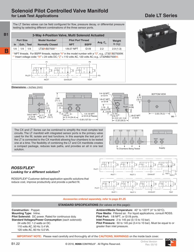
Dale LT SeriesSolenoid Pilot Controlled Valve Manifoldfor Leak Test Applications
3-Way 4-Position Valve, Multi Solenoid Actuated
Port Size Model Number* Pilot Port ThreadAvg. CV
Weightlb (kg)In Exh. Test Normally Closed NPT BSPP
1/4 1/4 1/4 LT32NB27500** 1/8-27 NPT G1/8 2.2 2.9 (1.3)
* NPT threads. For BSPP threads, replace “N” in the model number with a “D”, e.g., LT32DB27500W.** Insert voltage code: “W” = 24 volts DC; “Z” = 110 volts AC, 120 volts AC; e.g., LT32NB27500W.
0.75(19.1)
M6
1.00(25.4)
2.14 (54.4)0.42
(10.7)
0.77(19.5)
0.77(19.7)
0.78(19.7)
0.38(9.58)
0.59(14.9)
1.19(30.2)
3.00 (76.2)
1/8-27 NPTor G1/8
1/4-18 NPTor G1/4
1/8-27 NPTor G1/8
1/8-27 NPTor G1/8
(2 Places)
1/4-18 NPTor G1/4 (2 Places)
TEST INLET
P3
P2
EXHAUST
P1
PILOT
2.80(71.1)
0.52(13.2)
2.01 (51.1)2.33 (59.2)
BOTTOM VIEW
5.00 (127.0)
TEST
P1
INLET
PILOT
P2
P3
EXHAUST
TEST
PILOT
EXHAUSTINLET 1 INLET 2
Construction: Poppet. Mounting Type: Inline.Pilot Solenoid: DC power. Rated for continuous duty.Standard Voltages/Power Consumption (each solenoid): 24 volts DC: 1.2 watts on DC. 110 volts AC, 50 Hz: 5.4 VA. 120 volts AC, 60 Hz: 5.0 VA.
Ambient/Media Temperature: 40° to 120°F (4° to 50°C).Flow Media: Filtered air. For liquid applications, consult ROSS.Pilot Port: 1/8 NPT, or G1/8 ports.Inlet Pressure: 2 to 145 psi (0.13 to 10 bar).Pilot Pressure: 50 to 145 psi (3.4 to 10 bar). Must be equal to or greater than inlet pressure.
STANDARD SPECIFICATIONS (for valves on this page):
Accessories ordered separately, refer to page B1.25.
PILOT
EXHAUSTINLET 1 INLET 2 P1 P2TEST 1TEST 2
The CX and LT Series can be combined to simplify the most complex test circuits. The LT manifold with integrated sensor ports is the primary valve used for the fill, isolate and test functions. In this example the test port of the LT is connected to the CX manifold allowing four chambers to be tested one at a time. The flexibility of combining the LT and CX manifolds creates a compact package, reduces leak paths, and provides an all in one test solution.
2 2 2 2
To Chambers Being Tested
TEST INLET
Supply
The LT Series valves can be field configured for flow, pressure decay, or differential pressure testing by selecting different combinations of the three sensor ports.
ROSS/FLEX®
Looking for a different solution?
ROSS/FLEX® Customer defined application specific solutions that reduce cost, improve productivity and provide a perfect fit.
B1
B
Dimensions – inches (mm)

IMPORTANT NOTE: Please read carefully and thoroughly all of the CAUTIONS, WARNINGS on the inside back cover.
B1.23www.rosscontrols.comOnline VersionRev. 05/16
Dale LT SeriesSolenoid Pilot Controlled Valve Manifoldfor Leak Tight Applications
3-Way 4-Position Valve, Multi Solenoid Actuated
ThreadsPort Size Model Number Sensor Ports Pilot Port
ThreadAvg. CV
Weightlb (kg)In Exh. Test Normally Closed P1 P2 P3
NPT 1/4 1/4 1/4 LT32NB27500**01 1/8 1/8 1/8 1/8 NPT 0.9 3.6 (1.7)
BSPP 1/4 1/4 1/4 LT32DB27500**01 1/8 1/8 1/8 G 1/8 0.9 3.6 (1.7)
** Insert voltage code: “W” = 24 volts DC; “Z” = 110 volts AC, 120 volts AC; e.g., LT32NB27500W01.
Construction: Poppet. Mounting Type: Inline.Pilot Solenoid: DC power. Rated for continuous duty.Standard Voltages/Power Consumption (each solenoid): 24 volts DC: 1.2 watts on DC. 110 volts AC, 50 Hz: 5.4 VA. 120 volts AC, 60 Hz: 5.0 VA.
Ambient/Media Temperature: 40° to 120°F (4° to 50°C).Flow Media: Filtered air. For liquid applications, consult ROSS.Pilot Port: 1/8 NPT, or G1/8 ports.Inlet Pressure: Vacuum to 250 psi (vacuum to 17.2 bar).Pilot Pressure: 70 to 145 psi (4.8 to 17.2 bar).
STANDARD SPECIFICATIONS (for valves on this page):
Accessories ordered separately, refer to page B1.25.
The LT Series valves can be field configured for flow, pressure decay, or differential pressure testing by selecting different combinations of the three sensor ports.
4.65(118.1)
2.33(59.2)
0.49(12.5)
6.30 (159.9)
0.49(12.5)
0.31(7.8)
Ø0.19 (4.8)Ø0.33 (8.3)
1.00(25.4)
1.10(28.0)
1.00 (25.4)
0.83(21.0)
1.10(28.0)
5.00 (126.9)3.15 (80.0)
1.30(33.0)
0.50(12.7)
5.90 (149.8) 0.20(5.1)
1.75(4.45)TEST EXH. INLET
X1
P2
P3P1
1/4 or G1/4(3 places)
1/8 or G1/8
1/8 or G1/8P2
(plugged port)
P2
TEST
PILOT
EXHAUSTINLET 1 INLET 2
PILOT
EXHAUSTINLET 1 INLET 2 P1 P2TEST 1TEST 2
The CX and LT Series can be combined to simplify the most complex test circuits. The LT manifold with integrated sensor ports is the primary valve used for the fill, isolate and test functions. In this example the test port of the LT is connected to the CX manifold allowing four chambers to be tested one at a time. The flexibility of combining the LT and CX manifolds creates a compact package, reduces leak paths, and provides an all in one test solution.
ROSS/FLEX®
Looking for a different solution?
ROSS/FLEX® Customer defined application specific solutions that reduce cost, improve productivity and provide a perfect fit.
1 22 12 1
1/8 NPT or G1/8P2 Port
1/8 NPT or G1/8P3 Port
1/4 NPT or G1/4TEST
1/4 NPT or G1/4EXHAUST
1/4 NPT or G1/4INLET
1/8 NPT or G1/8
Pilot Supply
1/8 NPT or G1/8Plugged Port1/8 NPT
or G1/8P1 Port
B1
B
Dimensions – inches (mm)

B1.24 © 2016, ROSS CONTROLS®. All Rights Reserved.Online Version
Rev. 05/16
CP & CX Series Assembled Valve Manifold Configurator
This form can be used when your application requires either a CP or CX Series valve manifold with different valve functions to provide you with complete valve manifold assemblies to fit your precise requirements.
Manifolds can be ordered from two to ten stations. For other combinations, contact ROSS for more information.
Valve Position Number
Valve Model Number*
1
2
3
4
5
6
7
8
9
10
*Refer to CP or CX Valve product pages for Valve Model Numbers. Enter “Blank” to indicate base with blocking plate.
Example:
Valve Position Number
Valve Model Number**
1 CX14NB37511W
2 CX14NB37511W
3 CX24NB37511W
4 CX24NB37511W
5 Blank
6 CX14NB47511W
7 CX24NB47511W
8 CX14NB35511
9
10
**Example given for an eight station manifold.
Fax completed form to 1-706-356-3600 or e-mail to [email protected]
to obtain pre-assemble part number, price, and delivery.
Compatible Combinations
• Air Pilot & Solenoid Pilot Valves• 24 volts DC & 110 or 120 volts AC Solenoid Pilot Valves• Different port 2 sizes with same port 1 size
(i.e., valve 1 = 1/2” port 1 & 3/8” port 2; valve 2 = 1/2” port 1 & 1/2” port 2.
Name: Date:
Company Name:
Address:
City, State, Zip Code:
Tel: e-mail:
# of Stations 2 3 4 5 6 7 8 9 10
Port Thread: NPT BSPP
Valve Series: CP CX
Valve Type: 2/2 3/2
B1
B

IMPORTANT NOTE: Please read carefully and thoroughly all of the CAUTIONS, WARNINGS on the inside back cover.
B1.25www.rosscontrols.comOnline VersionRev. 05/16
Electrical Connectors for CP, CX Series Solenoid Pilot Controlled Valves.
Valve Type
Port Size
Electrical Connector
Form
Electrical Connectors Part Number
Lighted Connector Only Lighted Connector Pre-wired*
24 Volts DC 120 Volts AC 24 Volts DC 120 Volts AC
2/2 1/4 - 1 DIN 43650 Form C 2453K77-W 2453K77-Z 2476K77-W 2476K77-Z
2/2 11/2-21/2 DIN 43650 Form A 936K87-W 936K87-Z 720K77-W 720K77-Z
3/2 1/2 DIN 43650 Form C 2453K77-W 2453K77-Z 2476K77-W 2476K77-Z
3/2 1 DIN 43650 Form A 936K87-W 936K87-Z 720K77-W 720K77-Z
*Pre-wired connectors include a 2 meter (61/2 ft.) cord.
Accessories for Dale Series
Silencers
Electrical Connectors
Port Size
Thread Type
Model Number Avg. CV
Dimensions inches (mm) Weightlb (kg)NPT Threads BSPT Threads A B
1/4 Male 5500A2003 D5500A2003 2.1 0.9 (21) 2.2 (55) 0.1 (0.1)
3/8 Male 5500A3013 D5500A3013 2.7 0.9 (21) 2.2 (55) 0.1 (0.1)
3/8 Male 5500A3003 D5500A3003 4.3 1.3 (32) 3.5 (88) 0.2 (0.1)
1/2 Male 5500A4003 D5500A4003 4.7 1.3 (32) 3.6 (91) 0.2 (0.1)
3/4 Male 5500A5003 D5500A5003 11.5 2.0 (51) 5.3 (135) 0.6 (0.3)
1 Male 5500A6003 D5500A6003 14.6 2.0 (51) 5.4 (138) 0.6 (0.3)
Pressure Range: 0 to 150 psig (0 to 10.3 bar) maximum. Flow Media: Filtered air.
A
B
Electrical Connectors for LF, LX Series Solenoid Pilot Controlled Valves.
Valve Type
Port Size
Electrical Connector
Form
Electrical Connectors Part Number
Lighted Connector Only Lighted Connector Pre-wired*
24 Volts DC 120 Volts AC 24 Volts DC 120 Volts AC
2/2 3/8 - 1 DIN 43650 Form C 2453K77-W 2453K77-Z 2476K77-W 2476K77-Z
2/2 11/4-21/2 DIN 43650 Form A 936K87-W 936K87-Z 720K77-W 720K77-Z
*Pre-wired connectors include a 2 meter (61/2 ft.) cord.
Electrical Connectors for LT Series Solenoid Pilot Controlled Valves.
Valve Type
Port Size
Electrical Connector
Form
Electrical Connectors Part Number
Lighted Connector Only Lighted Connector Pre-wired*
24 Volts DC 120 Volts AC 24 Volts DC 120 Volts AC
1/4 3/8 - 1 DIN 43650 Form C 2453K77-W 2453K77-Z 2476K77-W 2476K77-Z
*Pre-wired connectors include a 2 meter (61/2 ft.) cord.
B1
B

2 © 2016, ROSS CONTROLS®. Content subject to change.
General Information
Thread Types by Model Prefix Letter
Pneumatic Port Prefix Threaded Electrical Threads Letter Opening
NPT (ANSI B2.1) None NPT
ISO 228 - DIN 259 Parallel, BSPP# C* —
ISO 228 - DIN 259 Parallel, BSPP# D G
ISO 228 - JIS B0203 Tapered# J ISO
SAE 1926- ISO 11926 S NPT
* Used only for filters, regulators, lubricators.# ISO 228 threads superseds BSPP, G and JIS thread types.
Order Placement
For order placement, consult ROSS or your local ROSS distributor.For a current list of countries and local distributors, visit ROSS’ website at www.rosscontrols.com.
Standard Specifications
The standard specifications for the products on each page of this catalog are given on the same page or referenced. For solenoid pilot valves, models with internal pilot supply are listed. Most models are also available for use with external pilot supply or have a built-in pilot supply selector valve.
The products in this catalog are intended for use in industrial pneumatic systems. Most products are adaptable to other uses and conditions not covered by the standard specifications given in this catalog. Weights shown are approximate and are subject to change. Dimensions given, unless otherwise noted, are envelope dimensions (not for mounting). Consult ROSS for further information.
Port Threads
Ports of valves and bases described in this catalog have NPT (ANSI B2.1) threads. Other thread types can be specified by putting an appropriate prefix letter on the model or part number when ordering.
Flow Ratings
Flow ratings are expressed as CV where CV = 1 corresponds to a steady state air flow of approximately 32 scfm under the following conditions: Inlet pressure = 100 psig (6.7 bar) Pressure drop = 10 psi (0.69 bar) Air temperature = 68°F (20°C) Relative humidity = 36 percent
Note: Because widely differing test standards are used to measure CV values, the figures given in this catalog should not be used to compare ROSS valves with those of other makers. The CV ratings given here are intended only for use with performance charts published by ROSS. The CV ratings are averages for the various flow paths through the valve and are for steady flow conditions.
Approvals and Certifications
ROSS products are designed to meet a number of industrial standards, including the Canadian Standards Association (C.S.A.) guidelines. For more information on specific product approvals, contact your local distributor or ROSS.
Solenoids
All ROSS standard solenoids are rated for continuous duty (unless noted otherwise) and will operate the valve within the air pressure range specified in this catalog.
Explosion-Proof Solenoid Pilot available, for more information consult ROSS.
Voltage & Hertz
When ordering a solenoid valve, also specify the desired solenoid voltage and hertz.
Recommended Solenoid Voltages: 100-110 volts, 50 Hz; 100-120 volts, 60 Hz; 24 volts DC; 110 volts DC.
In addition, the following voltages are available:
200, 220 volts, 50 Hz200, 240, 480 volts, 60 Hz
24, 48, 220 volts, 50 Hz240 volts, 60 Hz
200, 220 volts, 50 Hz200, 240 volts, 60 Hz.
For example: Model 2773B5001, 120 volts, 60 Hz. Model W6076B2401, 220 volts, 50 Hz.
Please note that not all configurations are available for all models.
For additional information or help with voltage configuration, please contact your local distributor or ROSS.
Port Identification
Valve symbols in this catalog conform to the ISO 1219-1:1991 standard of the International Organization for Standardization (ISO) and the SAE J2051 standard of the Society of Automotive Engineers (SAE) respectively.
Information or Technical AssistanceFor additional information or application assistance concerning ROSS products, consult ROSS or your local ROSS distributor (see contact information on the back cover).
Voltage Types by Model Suffix Letter
Voltage Suffix Letter
120 volts AC Z
220 volts AC Y
12 volts DC H
24 volts DC W
48 volts DC M
90 volts DC K
110 volts DC P
125 volts DC C

3www.rosscontrols.com
CAUTIONS, WARNINGS and STANDARD WARRANTY
PRE-INSTALLATION or SERVICE
1. Before servicing a valve or other pneumatic component, be sure that all sources of energy are turned off, the entire pneumatic system is shut off and exhausted, and all power sources are locked out (ref: OSHA 1910.147, EN 1037).2. All ROSS products, including service kits and parts, should be installed and/or serviced only by persons having training and experience with pneumatic equipment. Because any installation can be tampered with or need servicing after installation, persons responsible for the safety of others or the care of equipment must check every installation on a regular basis and perform all necessary maintenance.3. All applicable instructions should be read and complied with before using any fluid power system in order to prevent harm to persons or equipment. In addition, overhauled or serviced valves must be functionally tested prior to installation and use. If you have any questions, call your nearest ROSS location listed on the cover of this document.
4. Each ROSS product should be used within its specification limits. In addition, use only ROSS parts to repair ROSS products.
WARNING: Failure to follow these directions can adversely affect the performance of the product or result in the potential for human injury or damage to property.
FILTRATION and LUBRICATION
5. Dirt, scale, moisture, etc. are present in virtually every air system. Although some valves are more tolerant of these contaminants than others, best performance will be realized if a filter is installed to clean the air supply, thus preventing contaminants from interfering with the proper performance of the equipment. ROSS recommends a filter with a 5-micron rating for normal applications.6. All standard ROSS filters and lubricators with polycarbonate plastic bowls are designed for compressed air applications only. Do not fail to use the metal bowl guard, where provided, to minimize danger from high pressure fragmentation in the event of bowl failure. Do not expose these products to certain fluids, such as alcohol or liquefied petroleum gas, as they can cause bowls to rupture, creating a combustible condition, hazardous leakage, and the potential for human injury or damage to property. Immediately replace a crazed, cracked, or deteriorated bowl. When bowl gets dirty, replace it or wipe it with a clean dry cloth.
7. Only use lubricants which are compatible with materials used in the valves and other components in the system. Normally, compatible lubricants are petroleum based oils with oxidation inhibitors, an aniline point between 180°F (82°C) and 220°F (104°C), and an ISO 32, or lighter, viscosity. Avoid oils with phosphate type additives which can harm polyurethane components, potentially leading to valve failure which risks human injury, and/or damage to property.
AVOID INTAKE/EXHAUST RESTRICTION
8. Do not restrict the air flow in the supply line. To do so could reduce the pressure of the supply air below the minimum requirements for the valve and thereby cause erratic action.
9. Do not restrict a valve’s exhaust port as this can adversely affect its operation. Exhaust silencers must be resistant to clogging and must have flow capacities at least as great as the exhaust capacities of the valves. Contamination of the silencer can result in reduced flow and increased back pressure.
WARNING: ROSS expressly disclaims all warranties and responsibility for any unsatisfactory performance or injuries caused by the use of the wrong type, wrong size, or an inadequately maintained silencer installed with a ROSS product.
POWER PRESSES
10. Mechanical power presses and other potentially hazardous machinery using a pneumatically controlled clutch and brake mechanism must use a press control double valve with a monitoring device. A double valve without a self-contained monitoring device should be used only in conjunction with a control system which assures monitoring of the valve. All double valve installations involving hazardous applications should incorporate a monitoring system which inhibits further operation of the valve and machine in the event of a failure within the valve mechanism.
ENERGY ISOLATION/EMERGENCY STOP
11. Per specifications and regulations, ROSS L-O-X® and L-O-X® with EEZ-ON® operation products are defined as energy isolation devices, NOT AS EMERGENCY STOP DEVICES.
All products sold by ROSS CONTROLS are warranted for a one-year period [with the exception of all Filters, Regulators and Lubricators (“FRLs”) which are warranted for a period of seven years] from the date of purchase to be free of defects in material and workmanship. ROSS’ obligation under this warranty is
limited to repair or replacement of the product or refund of the purchase price paid solely at the discretion of ROSS and provided such product is returned to ROSS freight prepaid and upon examination by ROSS is found to be defective. This warranty becomes void in the event that product has been subject to misuse, misapplication, improper maintenance, modification or tampering.
THE WARRANTY EXPRESSED ABOVE IS IN LIEU OF AND EXCLUSIVE OF ALL OTHER WARRANTIES AND ROSS EXPRESSLY DISCLAIMS ALL OTHER WARRANTIES EITHER EXPRESSED OR IMPLIED WITH RESPECT TO MERCHANTABILITY OR FITNESS FOR A PARTICULAR PURPOSE. ROSS MAKES NO WARRANTY WITH RESPECT TO ITS PRODUCTS MEETING THE PROVISIONS OF ANY GOVERNMENTAL OCCUPATIONAL SAFETY AND/OR HEALTH LAWS OR REGULATIONS. IN NO EVENT IS ROSS LIABLE TO PURCHASER, USER, THEIR EMPLOYEES OR OTHERS FOR INCIDENTAL OR CONSEQUENTIAL DAMAGES WHICH MAY RESULT FROM A BREACH OF THE WARRANTY DESCRIBED ABOVE OR THE USE OR MISUSE OF THE PRODUCTS. NO STATEMENT OF ANY REPRESENTATIVE OR EMPLOYEE OF ROSS MAY EXTEND THE LIABILITY OF ROSS AS SET FORTH HEREIN.
STANDARD WARRANTY

Full-Service Global LocationsThere are ROSS Distributors Throughout the World
For a current list of countries and local distributors, visit ROSS’ website at www.rosscontrols.com.
To meet your requirements across the globe, ROSS distributors are located throughout the world. Through ROSS or its distributors, guidance is available for the selection of ROSS products, both for those using pneumatic components for the first time and those designing complex pneumatic systems.
Other literature is available for engineering, maintenance, and service requirements. If you need products or specifications not shown here, please contact ROSS or your ROSS distributor. They will be happy to assist you in selecting the best product for your application.
© 2016, ROSS CONTROLS. All Rights Reserved. Form ROSS-DalePrinted in the U.S.A. - Rev. 09/15Content subject to change.Revised 05/16, online version only.
ROSS CONTROLSU.S.A.
Tel: +1-248-764-1800Customer Svs. 1-800-GET-ROSSTechnical Svs. 1-888-TEK-ROSS
ROSS EUROPA GmbHGermany
Tel: [email protected] www.rosseuropa.com
ROSS ASIA K.K.Japan
Tel: +81-42-778-7251www.rossasia.co.jp
ROSS UK Ltd.United Kingdom
Tel: [email protected]
www.rossuk.co.uk
ROSS CONTROLS INDIA Pvt. Ltd.India
Tel: [email protected]
ROSS SOUTH AMERICA Ltda.Brazil
Tel: [email protected]
ROSS FRANCE S.A.S.France
Tel: +33-1-49-45-65-65www.rossfrance.com
ROSS CONTROLS (CHINA) Ltd.China
Tel: +86-21-6915-7961sales@rosscontrols.com.cnwww.rosscontrolschina.com
ROSS CANADACanada
Tel: [email protected]
6077170 CANADA INC. An Independent RepResentatIve