rosemount 5400m series - emerson electric · 2019-04-12 · marine application characteristics a...
TRANSCRIPT

www.EmersonRosemount.com/mtm
Reference Manual Marine Version Ed 01 Rev ABNovember 2012
Rosemount 5400M SeriesTwo-Wire Radar Level Transmitter

The Emerson logo is a trademark and service mark of Emerson Co. Rosemount TankRadar and the Rosemount logotype are registered trademarks of RosemountTank Radar AB. All rights reserved. All other marks are the property of their respective owners.
The content of this publication are presented for information purposes only, and while effort has been made to ensure their accuracy, they are not to be construed aswarranties or guarantees, expressed or implied, regarding the products or services described herein or their use or applicability. All sales are governed by our termsand conditions, which are available upon request. We reserve the right to modify or improve the designs or specifications of our products at any time without notice.Rosemount Tank Radar AB accepts no responsibility for any errors that may appear in this publication. As each system may be configured for each delivery, the content and illustrations in this manual may differ from your system.
Copyright © Rosemount Tank Radar AB, 2012Reference Manual Marine Version
1st edition Version ABNovember 2012
Rosemount 5400M
Marine Tank ManagementEmerson Process ManagementRosemount Tank Radar ABGamlestadsvägen 18BBox 13045SE-40251 GöteborgSweden

Reference Manual Marine Version Ed 01 Rev ABNovember 2012 Rosemount 5400M Series
www.EmersonProcess.com/mtm
Table of ContentsSECTION 1Introduction
Safety Messages . . . . . . . . . . . . . . . . . . . . . . . . . . . . . . . . . . . . . . . . . 1-1Manual Overview . . . . . . . . . . . . . . . . . . . . . . . . . . . . . . . . . . . . . . . . . 1-2Service Support . . . . . . . . . . . . . . . . . . . . . . . . . . . . . . . . . . . . . . . . . . 1-2Product Recycling/Disposal . . . . . . . . . . . . . . . . . . . . . . . . . . . . . . . . . 1-3
SECTION 2Transmitter Overview
Theory of Operation. . . . . . . . . . . . . . . . . . . . . . . . . . . . . . . . . . . . . . . 2-1Components of the transmitter . . . . . . . . . . . . . . . . . . . . . . . . . . . . . . 2-2System Architecture. . . . . . . . . . . . . . . . . . . . . . . . . . . . . . . . . . . . . . . 2-3Marine Application Characteristics . . . . . . . . . . . . . . . . . . . . . . . . . . . 2-4
Dielectric constant . . . . . . . . . . . . . . . . . . . . . . . . . . . . . . . . . . . . . 2-4Foam . . . . . . . . . . . . . . . . . . . . . . . . . . . . . . . . . . . . . . . . . . . . . . . 2-4Transition Zone. . . . . . . . . . . . . . . . . . . . . . . . . . . . . . . . . . . . . . . . 2-4
SECTION 3Mechanical Installation
Safety Messages . . . . . . . . . . . . . . . . . . . . . . . . . . . . . . . . . . . . . . . . . 3-1Installation Procedure . . . . . . . . . . . . . . . . . . . . . . . . . . . . . . . . . . . . . 3-2Placement Considerations. . . . . . . . . . . . . . . . . . . . . . . . . . . . . . . . . . 3-3
Free space requirements . . . . . . . . . . . . . . . . . . . . . . . . . . . . . . . . 3-3Pipes Intruding into the Radar Beam . . . . . . . . . . . . . . . . . . . . . . . 3-4
Location of Heating Coils . . . . . . . . . . . . . . . . . . . . . . . . . . . . . 3-4Coil Supports. . . . . . . . . . . . . . . . . . . . . . . . . . . . . . . . . . . . . . . 3-5
Transmitter Close to Bulkhead and in Narrow Wing Tanks . . . . . . 3-6Inclined Tank Bottom . . . . . . . . . . . . . . . . . . . . . . . . . . . . . . . . . . . 3-6Cargo Deep Well/Inlet . . . . . . . . . . . . . . . . . . . . . . . . . . . . . . . . . . 3-7Longitudinals or Frames on the Tank Bottom. . . . . . . . . . . . . . . . . 3-8Deflection Plates. . . . . . . . . . . . . . . . . . . . . . . . . . . . . . . . . . . . . . . 3-8Service Space and Orientation. . . . . . . . . . . . . . . . . . . . . . . . . . . . 3-9
Mounting Considerations . . . . . . . . . . . . . . . . . . . . . . . . . . . . . . . . . . . 3-9Transmitter Socket Requirements . . . . . . . . . . . . . . . . . . . . . . . . . 3-9Gasket Recommendation . . . . . . . . . . . . . . . . . . . . . . . . . . . . . . . . 3-9
General Recommendation . . . . . . . . . . . . . . . . . . . . . . . . . . . 3-10Mounting, Cable inlet . . . . . . . . . . . . . . . . . . . . . . . . . . . . . . . . . . . . . 3-10
Cable Gland . . . . . . . . . . . . . . . . . . . . . . . . . . . . . . . . . . . . . . . . . 3-10Cable Protection Hose . . . . . . . . . . . . . . . . . . . . . . . . . . . . . . . . . 3-11
SECTION 4Electrical Installation
Safety Messages . . . . . . . . . . . . . . . . . . . . . . . . . . . . . . . . . . . . . . . . . 4-1Cable/Conduit Entries . . . . . . . . . . . . . . . . . . . . . . . . . . . . . . . . . . . . . 4-2Grounding . . . . . . . . . . . . . . . . . . . . . . . . . . . . . . . . . . . . . . . . . . . . . . 4-3Cable Selection . . . . . . . . . . . . . . . . . . . . . . . . . . . . . . . . . . . . . . . . . . 4-3Hazardous Areas . . . . . . . . . . . . . . . . . . . . . . . . . . . . . . . . . . . . . . . . . 4-3External Circuit Breaker. . . . . . . . . . . . . . . . . . . . . . . . . . . . . . . . . . . . 4-3Power Requirements . . . . . . . . . . . . . . . . . . . . . . . . . . . . . . . . . . . . . . 4-3Connecting the Transmitter . . . . . . . . . . . . . . . . . . . . . . . . . . . . . . . . . 4-4Non-Intrinsically Safe Power Supply . . . . . . . . . . . . . . . . . . . . . . . . . . 4-5
Reference Manual Marine VersionEd 01 Rev AB
November 2012Rosemount 5400M Series
2
Intrinsically Safe Power Supply . . . . . . . . . . . . . . . . . . . . . . . . . . . . . . 4-6IS parameters . . . . . . . . . . . . . . . . . . . . . . . . . . . . . . . . . . . . . . 4-7
SECTION 5Service and Troubleshooting
Safety Messages . . . . . . . . . . . . . . . . . . . . . . . . . . . . . . . . . . . . . . . . . 5-1Troubleshooting Overview . . . . . . . . . . . . . . . . . . . . . . . . . . . . . . . . . . 5-2
Errors . . . . . . . . . . . . . . . . . . . . . . . . . . . . . . . . . . . . . . . . . . . . . . . 5-3Measurement Status . . . . . . . . . . . . . . . . . . . . . . . . . . . . . . . . . . . 5-4Volume Calculation Status . . . . . . . . . . . . . . . . . . . . . . . . . . . . . . . 5-5Analog Output Status . . . . . . . . . . . . . . . . . . . . . . . . . . . . . . . . . . . 5-6
SECTION 6Reference Data
Specifications. . . . . . . . . . . . . . . . . . . . . . . . . . . . . . . . . . . . . . . . . . . . 6-1
SECTION 7Product Certifications
Safety messages . . . . . . . . . . . . . . . . . . . . . . . . . . . . . . . . . . . . . . . . . 7-1EU Conformity . . . . . . . . . . . . . . . . . . . . . . . . . . . . . . . . . . . . . . . . . . . 7-2European ATEX Directive Information. . . . . . . . . . . . . . . . . . . . . . . . . 7-3
Intrinsic Safety . . . . . . . . . . . . . . . . . . . . . . . . . . . . . . . . . . . . . . . . 7-3Special Conditions for Safe Use (X) . . . . . . . . . . . . . . . . . . . . . 7-3
Flameproof . . . . . . . . . . . . . . . . . . . . . . . . . . . . . . . . . . . . . . . . . . . 7-4Special Conditions for Safe Use (X) . . . . . . . . . . . . . . . . . . . . . 7-4
Hazardous Locations Certifications . . . . . . . . . . . . . . . . . . . . . . . . . . . 7-5Factory Mutual (FM) Approvals . . . . . . . . . . . . . . . . . . . . . . . . . . . 7-5IECEx Approval . . . . . . . . . . . . . . . . . . . . . . . . . . . . . . . . . . . . . . . 7-6
EX Approval Drawings. . . . . . . . . . . . . . . . . . . . . . . . . . . . . . . . . . . . . 7-8
Reference Manual Marine Version Ed 01 Rev ABNovember 2012 Rosemount 5400M Series
www.EmersonProcess.com/mtm
Section 1 Introduction
Safety Messages . . . . . . . . . . . . . . . . . . . . . . . . . . . . . . . . . page 1-1Manual Overview . . . . . . . . . . . . . . . . . . . . . . . . . . . . . . . . page 1-2Service Support . . . . . . . . . . . . . . . . . . . . . . . . . . . . . . . . . page 1-2Product Recycling/Disposal . . . . . . . . . . . . . . . . . . . . . . . page 1-3
SAFETY MESSAGES Procedures and instructions in this manual may require special precautions to ensure the safety of the personnel performing the operations. Information that raises potential safety issues is indicated by a warning symbol ( ). Refer to the safety messages listed at the beginning of each section before performing an operation preceded by this symbol.
Failure to follow safe installation and service guidelines could result in death or serious injury
• Make sure only qualified personnel perform installation or service.
• Use the equipment only as specified in this manual. Failure to do so may impair the protection provided by the equipment.
• Any substitution of non-authorized parts or repair, other than exchanging the complete transmitter head or antenna assembly, may jeopardize safety and is prohibited.
• Unauthorized changes to the product are strictly prohibited as they may unintentionally and unpredictably alter performance and jeopardize safety. Unauthorized changes that interfere with the integrity of the welds or flanges, such as making additional perforations, compromise product integrity and safety. Equipment ratings and certifications are no longer valid on any products that have been damaged or modified without the prior written permission of Emerson Process Management. Any continued use of product that has been damaged or modified without prior written authorization is at the customer's sole risk and expense.
Explosions could result in death or serious injury
• Verify that the operating environment of the transmitter is consistent with the appropriate hazardous locations specifications.
• In an Explosion-proof/Flameproof installation, do not remove the transmitter cover when power is applied to the unit.
• Before connecting a HART® based communicator in an explosive atmosphere, make sure the instruments in the loop are installed in accordance with intrinsically safe or non-incendive field wiring practices.
Electrical shock can result in death or serious injury
• Avoid contact with the leads and terminals. High voltage that may be present on leads can cause electrical shock.
• Make sure the main power to the 5400M Series transmitter is off and the lines to any other external power source are disconnected or not powered while wiring the transmitter.

Reference Manual Marine VersionEd 01 Rev AB
November 2012Rosemount 5400M Series
2
MANUAL OVERVIEW This manual provides installation, configuration and maintenance information for the Rosemount 5400M Series Radar Transmitter.
Section 2: Transmitter Overview
• Theory of operation
• Descripton of the transmitter
• Process and vessel characteristics
Section 3: Mechanical Installation
• Mounting considerations
• Mounting
Section 4: Electrical installation
• Cable/conduit entries
• Grounding
• Cable selection
• Hazardous areas
• External circuit breaker
• Power requirements
• Connecting the transmitter
• Non-intrinsically safe power supply
• Intrinsically safe power supply
• Optional devices
Section 5: Service and Troubleshooting
• Troubleshooting
• Error and warning codes
• Communication errors
Appendix A: Reference Data
• Specifications
• Ordering Information
Appendix B: Product Certifications
• Examples of labels
• European ATEX Directive information
• FM approvals
• CSA approvals
• IECEx approvals
• TIIS approval
• NEPSI approvals
• Approval drawings
SERVICE SUPPORT Contact Marine Tank Management, Emerson Process Management, Rosemount Tank Radar AB at Gamlestadsvägen 18B, Box 13045SE-40251 Göteborg, Sweden.

Reference Manual Marine Version Ed 01 Rev ABNovember 2012 Rosemount 5400M Series
3
PRODUCT RECYCLING/DISPOSAL
Recycling of equipment and packaging should be taken into consideration and disposed of in accordance with local and national legislation/regulations.

Reference Manual Marine VersionEd 01 Rev AB
November 2012Rosemount 5400M Series
4

Reference Manual Marine Version Ed 01 Rev ABNovember 2012 Rosemount 5400M Series
www.EmersonProcess.com/mtm
Section 2 Transmitter Overview
Theory of Operation . . . . . . . . . . . . . . . . . . . . . . . . . . . . . . page 2-1Components of the transmitter . . . . . . . . . . . . . . . . . . . . . page 2-2System Architecture . . . . . . . . . . . . . . . . . . . . . . . . . . . . . . page 2-3Marine Application Characteristics . . . . . . . . . . . . . . . . . . page 2-4
THEORY OF OPERATION The Rosemount 5400M Series Radar Gauge is a smart, two-wire continuous level transmitter. A 5400 transmitter is installed at the top of the tank and emits short microwave pulses towards the product surface in the tank. When a pulse reaches the surface, part of the energy is reflected back to the antenna for subsequent processing by the transmitter electronics. The time difference between the transmitted and reflected pulse is detected by a micro-processor and is converted into a distance, which calculates the level.
The product level is related to the tank height and the measured distance by the following expression:
Level = Tank Height - Distance.
Figure 2-1. Measurement principle for the Rosemount 5400M Series.
Time Lev
elD
ista
nce
Tan
k H
eig
ht
Signal Amplitude

Reference Manual Marine VersionEd 01 Rev AB
November 2012Rosemount 5400M Series
2
COMPONENTS OF THE TRANSMITTER
The Rosemount 5400M Series Radar Gauge is available with a stainless steel housing containing advanced electronics for signal processing.
The radar electronics produces an electromagnetic pulse that is emitted through the antenna.
The transmitter head has separate compartments for electronics and terminals, and can be removed without opening the tank. The head has two entries for conduit/cable connections.
The tank connection consists of a Tank Seal and a flange (DIN or JIS).
Figure 2-2. Transmitter components.
Cable Entry:½" NPT.
Transmitter Head with Radar Electronics
Antenna
Display Panel Terminal side
Cable Entry:½" NPT.
Flange
Tank Seal

Reference Manual Marine Version Ed 01 Rev ABNovember 2012 Rosemount 5400M Series
3
SYSTEM ARCHITECTURE
The Rosemount 5400M Series Radar Transmitter is loop-powered, and uses the same two wires for power supply and output signal. The output is a 4-20 mA analog signal superimposed with a digital HART signal.
By using the optional HART Tri-loop, the HART signal can be converted up to three additional 4-20 mA analog signals.
With the HART protocol multidrop configuration is possible. In this case, communication is restricted to digital, since current is fixed to the 4 mA minimum value.
The transmitter can be connected to a Rosemount 751 Field Signal Indicator, or it can be equipped with an integral display.
The transmitter can easily be configured using a PC with the Rosemount Radar Master software. Rosemount 5400M Series transmitters can also be configured with the AMS® Suite and DeltaV™ software, and other tools that support Electronic Device Description Language (EDDL) functionality.
For HART communication a minimum load resistance of 250Ω within the loop is required.
Figure 2-3. HART system architecture
Integral Display
Rosemount Radar Master or AMS Suite
HART modem
Rosemount 751 Field Signal Indicator
3 x 4-20 mA
DCS
Rosemount 5400 Series Radar Transmitter
Tri-Loop

Reference Manual Marine VersionEd 01 Rev AB
November 2012Rosemount 5400M Series
4
MARINE APPLICATION CHARACTERISTICS
A calm surface gives better reflection than a turbulent surface. Maximum measurement range for a Marine application has taken turbulence surface in consideration and in-tank environment. For products with higher dielectric constant and/or lower turbulence surface measuring range can be extended. Please advice Rosemount Tank Radar AB for details.
Dielectric constant A key parameter for measurement performance is reflectivity. A high dielectric constant of the media provides better reflection and enables a longer measuring range.
Foam Rosemount 5400M Series Radar Transmitter measurement in foamy applications depends on the foam properties; light and airy or dense and heavy, high or low dielectrics, etc. If the foam is conductive and creamy, the transmitter may measure the surface of the foam. If the foam is less conductive, the microwaves may penetrate the foam, and measure the liquid surface.
Transition Zone The measurement accuracy is reduced within the Transition Zone region 6 in. (150 mm) from the lower end of the antenna. This is normally avoided by following installation drawings and by choice of gauge socket.

Reference Manual Marine Version Ed 01 Rev ABNovember 2012 Rosemount 5400M Series
www.EmersonProcess.com/mtm
Section 3 Mechanical Installation
Safety Messages . . . . . . . . . . . . . . . . . . . . . . . . . . . . . . . . . page 3-1Installation Procedure . . . . . . . . . . . . . . . . . . . . . . . . . . . . page 3-2Mounting Considerations . . . . . . . . . . . . . . . . . . . . . . . . . page 3-9Mounting, Cable inlet . . . . . . . . . . . . . . . . . . . . . . . . . . . . . page 3-10
SAFETY MESSAGES Procedures and instructions in this section may require special precautions to ensure the safety of the personnel performing the operations. Information that raises potential safety issues is indicated by a warning symbol ( ). Please refer to the following safety messages before performing an operation preceded by this symbol.
Failure to follow safe installation and service guidelines could result in death or serious injury
• Make sure only qualified personnel perform installation or service.
• Use the equipment only as specified in this manual. Failure to do so may impair the protection provided by the equipment.
• Any substitution of non-recognized spare parts may jeopardize safety. Repair, e.g. substitution of components etc. may also jeopardize safety and is under no circumstances allowed.
Explosions could result in death or serious injury
• Verify that the operating environment of the transmitter is consistent with the appropriate hazardous locations specifications.
• In an Explosion-proof/Flameproof installation, do not remove the transmitter cover when power is applied to the unit.
• Before connecting a HART® based communicator in an explosive atmosphere, make sure the instruments in the loop are installed in accordance with intrinsically safe or non-incendive field wiring practices.
Electrical shock can result in death or serious injury
• Avoid contact with the leads and terminals. High voltage that may be present on leads can cause electrical shock.
• Make sure the main power to the 5400M Series transmitter is off and the lines to any other external power source are disconnected or not powered while wiring the transmitter.

Reference Manual Marine VersionEd 01 Rev AB
November 2012Rosemount 5400M Series
2
INSTALLATION PROCEDURE
This is a recommended working procedure of how to perform the installation.
The procedure presents an overview of the installation steps.
NOTE!Please refer to Installation drawings for more detailed information.
1. Decide the location of the transmitter.
2. Manufacture the transmitter’s socket (if supplied by the yard), refer to drawings.
3. Cut the hole in the deck
4. Weld the socket to the deck.
5. Mount the transmitter on the socket with the appropriate gasket.
6. Lay out the cables.
7. Fasten the cable and strip the wires.Use the PTFE tape to seal gland and plug.
8. Connect the wires.
9. Fasten the lid.
NOTE!Retighten glands and clamp ring within one week!

Reference Manual Marine Version Ed 01 Rev ABNovember 2012 Rosemount 5400M Series
3
PLACEMENT CONSIDERATIONS
Before installing a Rosemount 5400M Series Transmitter, consider specific mounting requirements, vessel, and process characteristics.
The general recommendation in international (ISO) and API measurement standards for location is to place the transmitter as close to the tank center on deck as possible. This location minimizes the uncertainty from trim/list corrections, as well as avoids excessive liquid turbulence during open sea operations.
This is especially important for tankers, operating in high sea conditions such as shuttle tankers, FPSO’s etc. This reduces excessive errors in the trim/list correction of ullage, minimizes the liquid splashing from the bulkheads and is of essential importance to achieve an acceptable measurement.
Locating the transmitter close to the vertical line through the center of gravity of the tank, also provides the best accuracy for volume calculation.
Free space requirements When deciding the location of the transmitter on deck, the free space requirement must be considered. The radar beam must pass unobstructed to the tank bottom. This is the most important requirement in order to get a trouble-free operation of the transmitter. The ideal free space requirements for the transmitter is best described as a circular cone, centered around the antenna axis with an angle of 9°. See Figure 3-1 on page -4.
There can be certain exceptions from the ideal free space requirements, for example when the transmitter is installed close to a bulkhead. Exceptions with requirements and recommendations are described later on in this chapter.
All exceptions from the ideal free space requirements must be revised and approved by Rosemount Tank Radar AB before any installation arrangements are planned.
If there are any hesitations about the location of the transmitter, contact Rosemount Tank Radar AB.

Reference Manual Marine VersionEd 01 Rev AB
November 2012Rosemount 5400M Series
4
Figure 3-1. Free space requirements.
Pipes Intruding into the Radar Beam
One pipe with a diameter that equals to or is less than 56 mm (2”) can, without restriction, pass through the inner area of the radar beam. Another pipe, without flanged joints, does not seriously affect the performance and can be allowed outside a 9° cone centered around the antenna axis. In doubtful cases contact Rosemount Tank Radar AB for advice.
Location of Heating Coils
Heating coils, should if possible be located outside the radar beam so that the radar echo is unaffected within the free space requirements.
Reference Manual Marine Version Ed 01 Rev ABNovember 2012 Rosemount 5400M Series
5
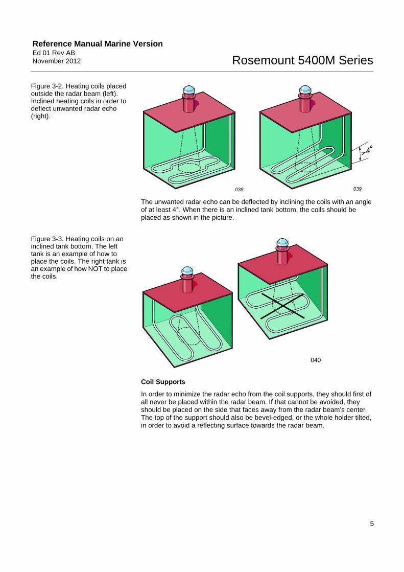
Figure 3-2. Heating coils placed outside the radar beam (left). Inclined heating coils in order to deflect unwanted radar echo (right).
The unwanted radar echo can be deflected by inclining the coils with an angle of at least 4°. When there is an inclined tank bottom, the coils should be placed as shown in the picture.
Figure 3-3. Heating coils on an inclined tank bottom. The left tank is an example of how to place the coils. The right tank is an example of how NOT to place the coils.
Coil Supports
In order to minimize the radar echo from the coil supports, they should first of all never be placed within the radar beam. If that cannot be avoided, they should be placed on the side that faces away from the radar beam’s center. The top of the support should also be bevel-edged, or the whole holder tilted, in order to avoid a reflecting surface towards the radar beam.

Reference Manual Marine VersionEd 01 Rev AB
November 2012Rosemount 5400M Series
6
Figure 3-4. Placement of coil support.
Transmitter Close to Bulkhead and in Narrow Wing Tanks
Because of circular polarization, there is no clearance distance requirement from the tank wall if it is flat and free of obstructions such as heating coils and ladders. The optimal location is 1/4 of the inner beam diameter from the tank wall.
Inclined Tank Bottom Avoid, if possible, to locate the transmitter over an inclined tank bottom. The bottom echo with an empty tank may be too weak for reliable indication. If a placement over an inclined tank bottom cannot be avoided, the transmitter should be placed over the deepest part of the tank.
If the bottom inclination exceeds 2°, a square steel target plate should be installed as a bottom reflector perpendicular to the ships vertical axis (within ±1°). It should be installed as deep in the tank as possible, however, the whole target plate must be inside the radar beam.
The target plate must be installed under the antenna, measured from the ship´s vertical axis below the antenna, and have a size according to the table below.
Table 3-1. Target plate size. .
The plate should be designed to endure high-pressure tank washing.
Do not mount the target plate in a way that creates a pocket. Mount in a way that allows cleaning.
Tank height Plate size Plate center from radar beam axis
(m) (mm) (mm)
0 - 5 120 x 120 max. 100
5 - 10 160 x 160 max. 200

Reference Manual Marine Version Ed 01 Rev ABNovember 2012 Rosemount 5400M Series
7
Figure 3-5. A target plate installed on an inclined tank bottom.
Cargo Deep Well/Inlet The transmitter must not be located directly above a cargo deep well or cargo inlet. The deep well or inlet can cause disturbances on the product surface when loading or discharging. These disturbances can prevent the measurement or cause inaccurate measurements.
Locate the transmitter so far away from cargo deep wells or inlets that the disturbances on the product surface do not intrude into the radar beam; hence the measurement will not be affected.
Figure 3-6. A cargo inlet at the bottom of the tank. To the left is an example of how to place the transmitter. To the right is an example of how NOT to place the transmitter.

Reference Manual Marine VersionEd 01 Rev AB
November 2012Rosemount 5400M Series
8
Figure 3-7. A cargo inlet at the top of the tank. To the left is an example of how to place the transmitter. To the right is an example of how NOT to place the transmitter.
Figure 3-8. A deep well in the bottom of the tank. To the left is an example of how to place the transmitter. To the right is an example of how NOT to place the transmitter.
Longitudinals or Frames on the Tank Bottom
Longitudinals, frames or pipes on the tank bottom may give a radar echo that can be mistaken for the cargo surface echo. To avoid this, the radar echo from these objects must be avoided, either by using deflection plates or an alternative location of the transmitter.
Deflection Plates If the interfering objects cannot be moved, deflection plates must be welded onto the objects. Deflection plates are necessary when any longitudinals intrude into the free space requirement which is best described as a 28° wide cone centered around the antenna axis. The deflection plates should be mounted so that the part of the beam that hits the deflection plates is deflected away from the radar beam’s center. Note also that deflection plates should never be used on heating coils.
Do not mount the deflection plate in a way that creates a pocket. Mount in a way that allows cleaning.
All longitudinals, frames, platforms etc. intruding into the free space requirement cone must be provided with deflection plates. The deflection plates must be 10% wider than the width of the top surface of the longitudinal to completely cover the beam. The plate must cover all parts of the interfering object that is in the beam.

Reference Manual Marine Version Ed 01 Rev ABNovember 2012 Rosemount 5400M Series
9
Figure 3-9. Deflection plates placed on a square frame and on a pipe.
Service Space and Orientation
The transmitter should be located so that there is free space above the transmitter in order to have the transmitter easily accessible for maintenance and service. See installation drawing for free space area.
Place the transmitter so that the cable inlet for the cable is directed towards center line.
Refer to the mechanical Installation drawings in your documentation binder for more detailed information.
MOUNTING CONSIDERATIONS
Transmitter Socket Requirements
The transmitter is to be mounted on a deck socket. Transmitter sockets are either delivered by Emerson Process Management (optional) or manufactured by the yard according to drawings supplied.
The transmitter must be installed so that it is always above the highest possible tank content level. The standard height of the socket is 375 mm. Please refer to the Installation Drawings.
The socket is welded to the deck when a suitable hole has been cut in deck satisfying the minimal requirement to avoid any disturbing echoes.
The socket must be installed so that the flange is horizontal at even keel within ± 1°.
Refer to installation drawings in your documentation binder for more detailed information.
Gasket Recommendation To properly seal a tank several factors have to be taken into consideration, such as the flatness of the transmitter flange, socket flange and the properties of the selected gasket. It is important that the selected type of gasket and its material can withstand the cargo and the pressure the tank is approved for.
One of the functions the gasket has is to compensate for irregularities between the socket flange and the transmitter flange. For the gasket to seal properly the socket flange and the transmitter flange must provide the gasket with the gasket minimum surface pressure.

Reference Manual Marine VersionEd 01 Rev AB
November 2012Rosemount 5400M Series
10
General Recommendation
The choice of gasket is usually made by the yard, as the end customer may have special requests concerning the selection of gasket. Due to the wide variety of gaskets and the properties they have, we recommend, as a general rule, a gasket which will allow at least 30% compression ratio relative to its thickness, the reason for this is to be able to compensate for any irregularities between the flanges.
The guide that follows below is only intended as a first step in the selection of what type of gasket to be used, the final decision is up to the yard.
Due to the fact that local manufacturing variations in the gasket composition are very common, always check that the selected gasket endures the exposition of the intended cargoes of the ship. Hence the different types of gasket materials listed below are only a rough guidance in the selection of the gasket.
MOUNTING, CABLE INLET
Cable Gland The cable gland prevents water from entering the transmitter housing through the cable inlet. Holes in the transmitter housing that are not used are deliv-ered with a plug. The cable gland must be tightened so that it is completely tight around the cable. Use the PTFE tape to properly seal gland and plug.
NOTE!Make sure the installation is performed in dry conditions!

Reference Manual Marine Version Ed 01 Rev ABNovember 2012 Rosemount 5400M Series
11
Cable Protection Hose
Figure 3-10. The Cable Protection Hose and the Cable gland, disassembled. For cable length, L, see table for installation data.
The Cable Protection Hose (CPH) is intended for flexible and mechanical protection of the cable connection to deck equipment. The standard hose is ventilated in order to drain water and protect from pressurized water ingress in the cable pipe. The ventilation holes are positioned in a vertical alignment. As the cabling for Rosemount 5400M is sealed at the cable gland a waterproof hose is not required. Tightness at cable gland is of utmost importance and hence require the hose to be round and smooth, do not use an oval shaped hose or hoses that are ribbed or indented in any other way.
Use the PTFE tape to seal gland and plug to the housing.
The CPH is mounted between the transmitter cable gland and the ship cable pipe to protect the cable. The inside is made of a nitrile rubber hose and the outside is made of chloroprene armored with textile spiral construction.
Table 3-2. .
Thread deck end ISO 228/1-G1 1/4” can also be fitted with optional JIS or DIN flanges on request.
Installation Data for the Cable Protection Hose
Cable Ø (mm)
Gland Internal Ø (mm)
External Ø (mm)
Bending radius
Max. Length L (mm)
6 - 13 M20 19 31 100 655

Reference Manual Marine VersionEd 01 Rev AB
November 2012Rosemount 5400M Series
12
Reference Manual Marine Version Ed 01 Rev ABNovember 2012 Rosemount 5400M Series
www.EmersonProcess.com/mtm
Section 4 Electrical Installation
Safety Messages . . . . . . . . . . . . . . . . . . . . . . . . . . . . . . . . . page 4-1Cable/Conduit Entries . . . . . . . . . . . . . . . . . . . . . . . . . . . . page 4-2Grounding . . . . . . . . . . . . . . . . . . . . . . . . . . . . . . . . . . . . . . page 4-3Cable Selection . . . . . . . . . . . . . . . . . . . . . . . . . . . . . . . . . . page 4-3Hazardous Areas . . . . . . . . . . . . . . . . . . . . . . . . . . . . . . . . page 4-3External Circuit Breaker . . . . . . . . . . . . . . . . . . . . . . . . . . . page 4-3Power Requirements . . . . . . . . . . . . . . . . . . . . . . . . . . . . . page 4-3Connecting the Transmitter . . . . . . . . . . . . . . . . . . . . . . . . page 4-4Non-Intrinsically Safe Power Supply . . . . . . . . . . . . . . . . page 4-5Intrinsically Safe Power Supply . . . . . . . . . . . . . . . . . . . . page 4-6
SAFETY MESSAGES Procedures and instructions in this section may require special precautions to ensure the safety of the personnel performing the operations. Information that raises potential safety issues is indicated by a warning symbol ( ). Please refer to the following safety messages before performing an operation preceded by this symbol.
Failure to follow safe installation and service guidelines could result in death or serious injury
• Make sure only qualified personnel perform installation or service.
• Use the equipment only as specified in this manual. Failure to do so may impair the protection provided by the equipment.
• Any substitution of non-recognized spare parts may jeopardize safety. Repair, e.g. substitution of components etc. may also jeopardize safety and is under no circumstances allowed.
Explosions could result in death or serious injury
• Verify that the operating environment of the transmitter is consistent with the appropriate hazardous locations specifications.
• In an Explosion-proof/Flameproof installation, do not remove the transmitter cover when power is applied to the unit.
• Before connecting a HART® based communicator in an explosive atmosphere, make sure the instruments in the loop are installed in accordance with intrinsically safe or non-incendive field wiring practices.
Electrical shock can result in death or serious injury
• Avoid contact with the leads and terminals. High voltage that may be present on leads can cause electrical shock.
• Make sure the main power to the 5400 Series transmitter is off and the lines to any other external power source are disconnected or not powered while wiring the transmitter.

Reference Manual Marine VersionEd 01 Rev AB
November 2012Rosemount 5400M Series
2
CABLE/CONDUIT ENTRIES
The electronics housing has two entries with ½ - 14 NPT threads.
Cable protective hoses delivered from Emerson Process Management requires special cable glands, supplied by Emerson Process Management.
Properly seal unused ports to prevent moisture or other contamination from entering the terminal compartment of the electronics housing. Install wiring with a drip loop with the bottom of the loop lower than the cable/conduit entry.
Figure 4-1. Cable Entries.
NOTE!Use the enclosed metal plug to seal the unused port. The temporary orange plastic plugs used at delivery are not sufficient seals! Failure to use the metal plug to seal the unused port invalidates product certification.Use the PTFE tape to seal metal plug.
Remove the orange protective plastic plugs, used for transportation.Seal any unused port with the enclosed metal plug.
Cable Entry Cable Entry

Reference Manual Marine Version Ed 01 Rev ABNovember 2012 Rosemount 5400M Series
3
GROUNDING The housing should always be grounded according to national and local electrical codes. Failure to do so may impair the protection provided by the equipment. The most effective grounding method is direct connection to earth ground with minimal impedance. There are two grounding screw connections provided. One is inside the Terminal compartment of the housing and the other is located on one of the cooling fins below the housing. The internal ground screw is identified by a ground symbol: .
NOTE!Using the threaded conduit connection for grounding may not be sufficient!
NOTE!After installation and commissioning, make sure that no ground currents exist from high ground potential differences in the installation.
CABLE SELECTION Use shielded twisted pair wiring for the Rosemount 5400 Series. The cables must be suitable for the supply voltage and approved for use in hazardous areas, where applicable. For instance, in the U.S., explosion-proof conduits must be used in the vicinity of the vessel. For the ATEX flameproof approval version of the Rosemount 5400 Series, suitable conduits with sealing device or flameproof (EEx d) cable glands must be used depending on local requirements.
Use 18 AWG to 12 AWG wiring to minimize the voltage drop to the transmitter.
HAZARDOUS AREAS When the Rosemount 5400 Series transmitter is installed in a hazardous area, all national and local regulations and specifications in applicable certificates must be observed.
EXTERNAL CIRCUIT BREAKER
For compliance with Low Voltage Directive 73/23/EEG, an external circuit breaker should be installed.
POWER REQUIREMENTS
Terminals in the transmitter housing provide connections for signal wiring.
The 5400 transmitter operates with the following power supplies:
Table 4-1. Minimum input voltage (UI) at different currents.
Hazardous approval
Current
3.75 mA 21.75 mA
Minimum input voltage (UI)
Non-Hazardous Installations and Intrinsically Safe Installations
16 Vdc 11 Vdc
Explosion-proof / Flameproof Installations
20 Vdc 15.5 Vdc

Reference Manual Marine VersionEd 01 Rev AB
November 2012Rosemount 5400M Series
4
CONNECTING THE TRANSMITTER
The Rosemount 5400 Series accepts power supplies ranging from 16 Vdc to 42.4 Vdc. It uses 4-20 mA power superimposed with a HART signal.
To connect the transmitter:
1. Make sure the housing is grounded (including IS ground inside the Terminal compartment) according to Hazardous Locations Certifications, national, and local electrical codes.
2. Make sure the power supply is disconnected.
3. Remove the terminal block cover.
4. Pull the cable through the cable gland/conduit. For Explosion-proof/ Flameproof installations, use cable glands or conduit entry devices certified Explosion-proof or Flameproof. Install the wiring with a drip loop, with the bottom of the loop lower than the cable/conduit entry.
5. Connect the wires according to Figure 4-3 for non-intrinsically safe power supplies, and according to Figure 4-6 for intrinsically safe power supplies.
6. Remove the orange protective plastic plugs used for transportation and seal any unused port with the enclosed metal plug.
7. Mount the cover and tighten the cable gland, making sure the cover is secure to meet explosion-proof requirements.For ATEX and IECEx installations, lock the cover with the Locking screw
.
8. Connect the power supply.
NOTE!Use PTFE tape or other sealant at the NPT threads in the Cable Entries.
Figure 4-2. Terminal compartment and external ground screw.
5
11
3
2
4
Cable entries.
Internal Ground screw.
Terminals for signal and power supply.
Locking screw.
External Ground screw.
Reference Manual Marine Version Ed 01 Rev ABNovember 2012 Rosemount 5400M Series
5
NON-INTRINSICALLY SAFE POWER SUPPLY
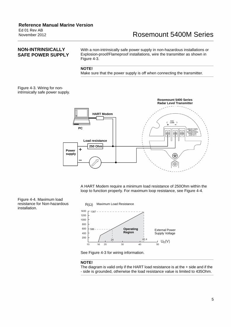
With a non-intrinsically safe power supply in non-hazardous installations or Explosion-proof/Flameproof installations, wire the transmitter as shown in Figure 4-3.
NOTE!Make sure that the power supply is off when connecting the transmitter.
Figure 4-3. Wiring for non-intrinsically safe power supply.
A HART Modem require a minimum load resistance of 250Ohm within the loop to function properly. For maximum loop resistance, see Figure 4-4.
Figure 4-4. Maximum load resistance for Non-hazardous installation.
See Figure 4-3 for wiring information.
NOTE!The diagram is valid only if the HART load resistance is at the + side and if the - side is grounded, otherwise the load resistance value is limited to 435Ohm.
Power supply
Load resistance
HART Modem
Rosemount 5400 Series Radar Level Transmitter
PC
250 Ohm
Operating Region
Maximum Load Resistance
External Power Supply Voltage

Reference Manual Marine VersionEd 01 Rev AB
November 2012Rosemount 5400M Series
6
Figure 4-5. Maximum load resistance for Explosion-Proof/ Flameproof installation.
See Figure 4-6 for wiring information.
NOTE!For Explosion-proof/Flameproof installations make sure the transmitter is grounded to the I.S. ground terminal inside the terminal compartment in accordance with national and local electrical codes.
INTRINSICALLY SAFE POWER SUPPLY
With an intrinsically safe power supply, wire the transmitter as shown in Figure 4-6.
NOTE!Make sure the instruments in the loop are installed according to intrinsically safe field wiring practices.
Figure 4-6. Wiring diagram for intrinsically safe power supply.
A HART Modem require a minimum load resistance within the loop of 250Ohm to function properly. For maximum load resistance see Figure 4-7.
NOTEThis diagram is valid only if the HART load resistance is at the + side and if the - sideis grounded, otherwise the maximum load resistance is limited to 435Ohm.
Operating Region
Maximum Load Resistance
External Power Supply Voltage
Power supply
HART Modem
Rosemount 5400 Series Radar Level Transmitter
Approved IS Barrier
Load resistance
250 Ohm
PC
Reference Manual Marine Version Ed 01 Rev ABNovember 2012 Rosemount 5400M Series
7
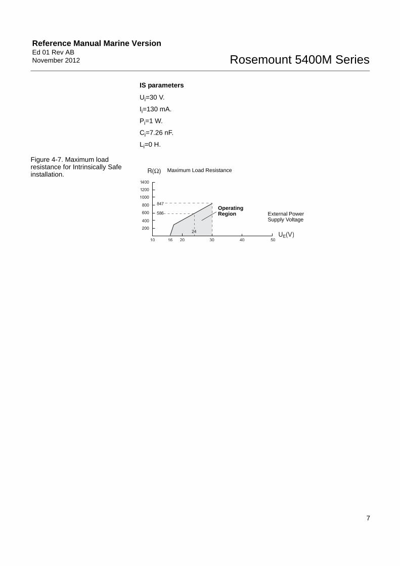
IS parameters
Ui=30 V.
Ii=130 mA.
Pi=1 W.
Ci=7.26 nF.
Li=0 H.
Figure 4-7. Maximum load resistance for Intrinsically Safe installation.
Operating Region
Maximum Load Resistance
External Power Supply Voltage

Reference Manual Marine VersionEd 01 Rev AB
November 2012Rosemount 5400M Series
8

Reference Manual Marine Version Ed 01 Rev ABNovember 2012 Rosemount 5400M Series
www.EmersonProcess.com/mtm
Section 5 Service and Troubleshooting
Safety Messages . . . . . . . . . . . . . . . . . . . . . . . . . . . . . . . . . page 5-1Troubleshooting Overview . . . . . . . . . . . . . . . . . . . . . . . . . page 5-2
SAFETY MESSAGES Procedures and instructions in this manual may require special precautions to ensure the safety of the personnel performing the operations. Information that raises potential safety issues is indicated by a warning symbol ( ). Refer to the safety messages listed at the beginning of each section before performing an operation preceded by this symbol.
NOTE!The antenna seal assembly, under no circumstances, should be disassembled.
Failure to follow these installation guidelines could result in death or serious injury.
• Make sure only qualified personnel perform the installation.
• Use the equipment only as specified in this manual. Failure to do so may impair the protection provided by the equipment.
Explosions could result in death or serious injury.
• Verify that the operating environment of the transmitter is consistent with the appropriate hazardous locations certifications.
• Before connecting a HART®-based communicator in an explosive atmosphere, make sure the instruments in the loop are installed in accordance with intrinsically safe or non-incendive field wiring practices.
• Any substitution of non-recognized parts may jeopardize safety. Repair, e.g. substitution of components etc., may also jeopardize safety and is under no circumstances allowed.
• Substitution of components may impair Intrinsic Safety.
Electrical shock could cause death or serious injury.
• Use extreme caution when making contact with the leads and terminals.
• To prevent ignition of flammable or combustible atmospheres, disconnect power before servicing.
High voltage that may be present on leads could cause electrical shock:
• Avoid contact with leads and terminals.
• Make sure the main power to the 5400 transmitter is off and the lines to any other external power source are disconnected or not powered while wiring the transmitter.

Reference Manual Marine VersionEd 01 Rev AB
November 2012Rosemount 5400M Series
2
TROUBLESHOOTING OVERVIEW
Table 5-1 below gives information on the possible causes of system malfunctions. It also lists the symptoms and necessary actions to be taken.
Table 5-1. Troubleshooting chart
Symptom Possible cause Action
No level reading• Power disconnected• Data communication cables
disconnected
• Check the power supply• Check the cables for serial data communication• Check LED/Display
No HART communication
• COM Port configuration does not match the connected COM Port
• Cables may be disconnected• Wrong HART address is used• Hardware failure• HART resistor
• Check that correct COM Port is selected in the HART server (see “Specifying the COM Port” on page -14)
• Check the COM port buffer, “Specifying the COM Port” on page -14
• Check wiring diagram• Verify that the 250 Ohm resistor is in the loop, see
Figure 4-10 on page -10• Check cables• Make sure that correct HART short address is used. Try
address=0• Check the COM Port Buffer setting, see page -14• Check Analog Output current value to verify that
transmitter hardware works
Analog Out is set in Alarm• Measurement Failure or
Transmitter Failure
• Check ambient temperature(1)
• Restart transmitter• Contact Emerson Process Management Service
Department
Incorrect level reading• Configuration error• Disturbing objects in the tank
• Check ambient temperature(2)
• Restart transmitter• Contact Emerson Process Management Service
Department
Integral display does not work
• Check the display configuration in Rosemount Radar Master (open menu Setup>General)
• Diagnostics• Contact Emerson Process Management Service
Department(3)
Temperature Measurement Failure
• Check ambient temperature(4)
• Restart transmitter• Contact Emerson Process Management Service
Department
Level Measurement Failure• Check Power Supply• Check the transmitter configuration• Check that the mechanical installation is correct
Volume Measurement Failure• Restart transmitter• Check transmitter configuration using PC Based
configuration tool
No surface echo
• Check signal strength• Restart transmitter• Contact Emerson Process Management Service
Department
(1) If the 5400 transmitter has been exposed to temperatures outside the specified limits, the device may stop its normal operation.(2) If the 5400 transmitter has been exposed to temperatures outside the specified limits, the device may stop its normal operation.
(3) A malfunctioning display panel may only be replaced by service personnel at Emerson Process Management Service Department.(4) If the 5400 transmitter has been exposed to temperatures outside the specified limits, the device may stop its normal operation.

Reference Manual Marine Version Ed 01 Rev ABNovember 2012 Rosemount 5400M Series
3
Errors Error messages that may be displayed on the Integral Display, in AMS, or in the Rosemount Radar Master (RRM) program, are shown in Table 5-2. Errors normally result in Analog Output alarm.
Errors are indicated in RRM in the Diagnostics window.
Table 5-2. Error messages.
Message Description Action
RAM Error
An error in the transmitter data memory (RAM) has been detected during the startup tests. Note: this resets the transmitter automatically.
Contact Emerson Process Management Service Department.
FPROM Error
An error in the transmitter program memory (FPROM) has been detected during the startup tests. Note: this resets the transmitter automatically.
Contact Emerson Process Management Service Department.
HREG Error
An error in the transmitter configuration memory (EEPROM) has been detected. The error is either a checksum error that can be solved by loading the default database or a hardware error.NOTE: the default values are used until the problem is solved.
Load default database and restart the transmitter. Contact Emerson Process Management Service Department if the problem persists.
MWM Error An error in the microwave module.Contact Emerson Process Management Service Department.
Display Error An error in the LCD.Contact Emerson Process Management Service Department.
Modem Error Modem hardware failure.Contact Emerson Process Management Service Department.
Analog Out Error An error in the Analog Out Module.Contact Emerson Process Management Service Department.
Internal Temp ErrorAn error in the internal temperature measurement.
Contact Emerson Process Management Service Department.
Other HW ErrorAn unspecified hardware error has been detected.
Contact Emerson Process Management Service Department.
Meas ErrorA serious measurement error has been detected.
Contact Emerson Process Management Service Department.
Config Error
At least one configuration parameter is outside allowed range. NOTE: the default values are used until the problem is solved.
Contact Emerson Process Management Service Department
SW ErrorAn error has been detected in the transmitter software.
Contact Emerson Process Management Service Department.

Reference Manual Marine VersionEd 01 Rev AB
November 2012Rosemount 5400M Series
4
Measurement Status Measurement Status messages that may appear on the Integral Display are shown in Table 5-3:
Table 5-3. Measurement status.
Message Description Action
Full tankThe level measurement is in Full Tank state. The transmitter waits for the surface echo to be detected at the top of the tank.
The transmitter leaves the Full Tank state when the product surface gets below the Full Tank Detection Area, see “Full Tank Handling” on page -5 and “Full Tank Handling” on page -10.
Empty tank
The level measurement is in Empty Tank state. The transmitter waits for the surface echo to be detected at the bottom of the tank.
The transmitter leaves the Empty Tank state when the product surface gets above the Empty Tank Detection Area, see “Empty Tank Handling” on page -4 and “Empty Tank Handling” on page -7.
Reference pulse invalidAn error in the reference pulse in the last sampled tank signal.
Check Warning messages. If MicroWave Module (MWM) Warning is active, this might indicate a transmitter error. Contact Emerson Process Management Service Department.
Sweep linearization warning The sweep is not correctly linearized.
Check Warning messages. If MWM Warning is active, this might indicate a transmitter error. Contact Emerson Process Management Service Department.
Tank signal clip warning The last Tank Signal was clipped.
Check Warning Messages. If MWM Warning is active, this might indicate a transmitter error. Contact Emerson Process Management Service Department.
No surface echoThe Surface Echo Pulse cannot be detected.
Check if the configuration can be changed so that the surface echo can be tracked in this current region.
Predicted levelThe presented level is predicted. The surface echo could not be detected.
See No surface echo above.
Sampling failed The sampling of the last tank signal failed. Check Warning Messages.
Invalid volume value The given volume value is invalid. Check Volume Status for details.
Simulation ModeThe simulation mode is active. The presented measurement values are simulated.
No action needed.
Advanced Simulation ModeThe advanced simulation mode is active. The given measurements are simulated.
Contact Rosemount Tank Radar AB.
Tracking Extra EchoThe transmitter is in the empty tank state tracking an extra echo.
Contact Rosemount Tank Radar AB.
Bottom Projection The bottom projection function is active. Contact Rosemount Tank Radar AB.
Using pipe measurement Pipe Measurement is active. No action needed.
Surface close to registered false echo.
Close to a registered false echo measurement accuracy may be slightly reduced.
By using the Register False Echo function, the transmitter can track the product surface in the vicinity of disturbing objects. Contact Rosemount Tank Radar AB.
Sudden level jump detected.This may result from various measurement problems.
Check the tank to find out what causes problem tracking the surface.

Reference Manual Marine Version Ed 01 Rev ABNovember 2012 Rosemount 5400M Series
5
Volume Calculation Status
Volume Calculation Status messages that may appear on the Integral Display are shown in Table 5-4:
Table 5-4. Volume status.Message Description Action
Level is below lowest strapping point.
The measured level is below the lowest point in the given strapping table.
For a correct volume calculation in this region, change the strapping table.
Level is above highest strapping point.
The measured level is above the highest point in the given strapping table.
For a correct volume calculation in this region, change the strapping table.
Level out of range.The measured level is outside the given tank shape.
Check if the correct tank type is chosen, and check the configured Tank Height.
Strap table length not valid.The configured strap table length is too small or too large.
Change the strapping table size to a valid number of strapping points. A maximum number of 20 strapping points can be entered.
Strap table not valid.The strapping table is not correctly configured.
Check that both level and volume values in the strapping table are increasing with strapping table index.
Level not valid.The measured level is not valid. No volume value can be calculated.
Check Measurement Status, Warning, and Error Messages.
Volume configuration missing.No volume calculation method is chosen.
Configure Volume.
Volume not valid. The calculated volume is not valid.Check the other volume status messages for the reason.

Reference Manual Marine VersionEd 01 Rev AB
November 2012Rosemount 5400M Series
6
Analog Output Status Analog Output Status messages that may appear on the Integral Display are shown in Table 5-5:
Table 5-5. Analog Output status.
Message Description Action
Not connectedAnalog output hardware is not connected.
Contact Emerson Process Management Service Department.
Alarm Mode The analog output is in Alarm Mode.Check Error and Warning Messages to find the reason for the Alarm.
SaturatedThe analog output signal value is saturated, i.e. equal to the saturation value.
No action needed.
MultidropThe transmitter is in Multidrop Mode. The analog output is fixed at 4 mA.
This is the normal setting when a device is used in Multidrop configuration.
Fixed Current modeThe analog output is in fixed current mode.
This mode is used when calibrating the Analog Output channel.
Invalid LimitsThe given Upper and Lower Range Values are invalid.
Check that the difference between the Upper and Lower Range Value is greater than the Minimum Span.

Reference Manual Marine Version Ed 01 Rev ABNovember 2012 Rosemount 5400M Series
www.EmersonProcess.com/mtm
Section 6 Reference DataSPECIFICATIONS
General
Product Rosemount 5400 Series Radar Level Transmitter
Measurement PrinciplePulsed, free propagating radar5402: ~26 GHz
Microwave Output Power < 1 mW
Beam Angle 4" Cone Antenna 9°
Measuring Performance
Measuring Range 30 ft (10 m) from flange
Instrument Accuracy at reference conditions(1) (2) 5402: ± 0.1 in. (± 3 mm)
Repeatability ± 0.04 in. (± 1 mm) at 16.4 ft (5 m) distance
Resolution 0.04 in. (1 mm)
Near Zone Distance 1.3 ft (0.4 m) from lower end of the antenna
Near Zone Accuracy 5402: ± 0.6 in. (± 15 mm)
Transition Zone(3) 6 in. (150 mm) from lower end of the antenna
Minimum Dielectric Constant εr = 1.4
Temperature Drift 0.05 %/10 K in temperature range -40°F to 176°F (-40°C to 80°C)
Update Interval 1 second
Max Level Rate 1.6 in./s (40 mm/s) as default, adjustable to 7.9 in./s (200 mm/s)
Display / Configuration / Communication
Integral Display5-digit integral display. The process variables listed below can be presented. If more than one variable is chosen, carousel toggling of data is used. The display also shows diagnostics and error information.
Output VariablesLevel, Distance, Volume, Level Rate, Signal Strength, Internal Temperature, Analog Output Current, and % of Range
Output Units
Level and Distance: ft, inch, m, cm or mmVolume: ft3, inch3, US gals, Imp gals, barrels, yd3, m3, or litersLevel Rate: ft/s, m/sTemperature: °F, °C
Configuration ToolsHART®: Rosemount RadarMaster, Rosemount 275/375 Handheld Communicator, AMS Suite or any other EDDL or enhanced-EDDL host.

Reference Manual Marine VersionEd 01 Rev AB
November 2012Rosemount 5400M Series
2
Electric
Terminal Supply Voltage See “Power Requirements” on page -3
Internal Power Consumption < 50 mW in normal operation
Output HART® 4-20 mA current loop
Signal on Alarm (configurable), HART®High=21.75 mA (standard setting)Low=3.75 mA (option, model code C8)Namur NE43: High=22.5 mA (option, model code C4)
Saturation Levels, HART® Standard: Low=3.9 mA, High=20.8 mANamur NE43: Low=3.8 mA, High=20.5 mA
IS Parameters See “Product Certifications” on page -1
Cable EntryTwo integrated ½-in. NPT threads. One metal plug to seal any unused ports and one cable gland is enclosed with the transmitter delivery.
Output Cabling 18-12 AWG, twisted shielded pairs
Mechanical
Antennas 4” cone antenna
Material Exposed to Tank Atmosphere
Cone Antenna• 316 / 316 L SST (EN 1.4404) • PTFE fluoropolymer• O-ring material, fluorosilicone
Housing / Enclosure SST Grade CF8M (ASTM A743)
Dimensions and Weights 11 kg (DN100 PN16/ JIS 10K-100A), 12.5kg (DN150 PN16 /JIS 10K – 150A).
Environment
Ambient Temperature(4) LCD readable in: -4°F to 158°F (-20°C to 70°C).
Storage Temperature -58°F to 194°F (-50°C to 90°C). LCD: -40°F to 185°F (-40°C to 85°C)
Flange Temperature 120°C for 10K and 100°C for PN16 .
Process Pressure PN16 / 10K .
Humidity 0 - 100% Relative Humidity, non condensating
Factory Sealed Yes
Ingress Protection Type 4X, IP66, IP67
EU Directive compliance CE mark, 93/68/EEC
Radio Approvals(5)(6) FCC part 15C (1998)(7), R&TTE (EU directive 1999/5/EC), and IC (RSS210-5)
Pressure Equipment Directive (PED) 97/23/EC
Certification Marine type approved according to E10 IACS E10, ABS, BV, DNV, GL, LR, RS
(1) Ideal metal plate with no disturbing objects. Temperature: + 68 °F (20 °C). Pressure: 14-15 psi (960-1060 mbar). Humidity: 25-75 % RH.
(2) If the reference conditions are not met, an offset adjustment for the zero reference point may be necessary. The offset may be up to ± 10 mm.(3) The measurement accuracy is reduced within the Transition Zone region 6 in. (150 mm) from the lower end of the antenna.(4) Temperature may be limited by the selected product certificate, see “Product Certifications” on page -1.(5) Only a limited selection is presented. Contact your local Emerson Process Management representative for more information.(6) For Japan: “Install device on tanks or pipes made of metal”.(7) For 5402: “This device is authorized for use in tank-mounted applications, including metal tanks as well as concrete, plastic, glass and other non-conductive
tanks.”
Reference Manual Marine Version Ed 01 Rev ABNovember 2012 Rosemount 5400M Series
www.EmersonProcess.com/mtm
Section 7 Product Certifications
Safety messages . . . . . . . . . . . . . . . . . . . . . . . . . . . . . . . . . page 7-1EU Conformity . . . . . . . . . . . . . . . . . . . . . . . . . . . . . . . . . . . page 7-2European ATEX Directive Information . . . . . . . . . . . . . . . page 7-3Hazardous Locations Certifications . . . . . . . . . . . . . . . . . page 7-5EX Approval Drawings . . . . . . . . . . . . . . . . . . . . . . . . . . . . page 7-8
SAFETY MESSAGES Procedures and instructions in this section may require special precautions to ensure the safety of the personnel performing the operations. Information that raises potential safety issues is indicated by a warning symbol ( ). Please refer to the following safety messages before performing an operation preceded by this symbol.
Explosions could result in death or serious injury:
Verify that the operating environment of the transmitter is consistent with the appropriate hazardous locations certifications.
Before connecting a HART-based communicator in an explosive atmosphere, make sure the instruments in the loop are installed in accordance with intrinsically safe or non-incendive field wiring practices.
Do not remove the transmitter cover in explosive atmospheres when the circuit is alive.
Failure to follow safe installation and servicing guidelines could result in death or serious injury:
Make sure the transmitter is installed by qualified personnel and in accordance with applicable code of practice.
Use the equipment only as specified in this manual. Failure to do so may impair the protection provided by the equipment.
Do not perform any service other than those contained in this manual unless you are qualified.
Substitution of components may impair Intrinsic Safety.
To prevent ignition of flammable or combustible atmospheres, disconnect power before servicing.
Reference Manual Marine VersionEd 01 Rev AB
November 2012Rosemount 5400M Series
2
EU CONFORMITY The EC declaration of conformity for all applicable European directives for this product can be found on the Emerson Process Management website at www.emersonprocess.com/mtm. A hard copy may be obtained by contacting our local sales representative.
High voltage that may be present on leads could cause electrical shock:
Avoid contact with leads and terminals.
Make sure the main power to the Radar Transmitter is off and the lines to any other external power source are disconnected or not powered while wiringthe transmitter.

Reference Manual Marine Version Ed 01 Rev ABNovember 2012 Rosemount 5400M Series
3
EUROPEAN ATEX DIRECTIVE INFORMATION
Intrinsic Safety The Rosemount 5400 Series Transmitter with the following attached label has been certified to comply with Directive 94/9/EC of the European Parliament and the Council as published in the Official Journal of the European Communities No. L 100/1 on 19-April-1994.
Figure 7-1. Approval Label ATEX
I1 The following information is provided as part of the label of the transmitter:
• Name and address of the manufacturer (Rosemount).
• CE Conformity Marking
• Complete model number
• The serial number of the device
• Year of construction
• Marking for explosion protection:
• EEx ia IIC T4 (-50 °C ≤ Ta ≤ +70 °C)(1)
• 4-20 mA/HART model: Ui=30 V, Ii=130 mA, Pi=1.0 W, Ci=7.26 nF, Li=0.
• Nemko ATEX certificate number: Nemko 04ATEX1073X
• Installation Drawing: 9150 079-907
Special Conditions for Safe Use (X)
The intrinsically safe circuits do not withstand the 500V AC test as specified in EN 50020 clause 6.4.12.
Parts of the rod-antenna and the All PTFE antenna are non-conducting and the area of the non-conducting part exceeds the maximum permissible areas for Group IIC according to EN 50014 clause 7.3 (20 cm2) and Category II 1 G according to EN 50284 clause 4.4.3 (4 cm2). Therefore, when the antenna is used in a potentially explosive atmosphere, appropriate measures must be taken to prevent electrostatic discharge.
Impact and friction hazards need then to be considered according to EN 50284 clause 4.3.1 when the transmitter and part of antennas exposed to the exterior atmosphere of the tank is made with light metal alloys and used in category II 1 G.(1) Other temperature restrictions may apply, please refer to “Temperature and Pressure Rat-
ings” on page -4.
Reference Manual Marine VersionEd 01 Rev AB
November 2012Rosemount 5400M Series
4
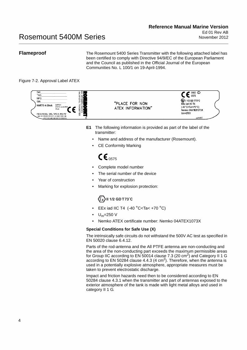
Flameproof The Rosemount 5400 Series Transmitter with the following attached label has been certified to comply with Directive 94/9/EC of the European Parliament and the Council as published in the Official Journal of the European Communities No. L 100/1 on 19-April-1994.
Figure 7-2. Approval Label ATEX
E1 The following information is provided as part of the label of the transmitter:
• Name and address of the manufacturer (Rosemount).
• CE Conformity Marking
• Complete model number
• The serial number of the device
• Year of construction
• Marking for explosion protection:
• EEx iad IIC T4 (-40 °C<Ta< +70 °C)
• Um=250 V
• Nemko ATEX certificate number: Nemko 04ATEX1073X
Special Conditions for Safe Use (X)
The intrinsically safe circuits do not withstand the 500V AC test as specified in EN 50020 clause 6.4.12.
Parts of the rod-antenna and the All PTFE antenna are non-conducting and the area of the non-conducting part exceeds the maximum permissible areas for Group IIC according to EN 50014 clause 7.3 (20 cm2) and Category II 1 G according to EN 50284 clause 4.4.3 (4 cm2). Therefore, when the antenna is used in a potentially explosive atmosphere, appropriate measures must be taken to prevent electrostatic discharge.
Impact and friction hazards need then to be considered according to EN 50284 clause 4.3.1 when the transmitter and part of antennas exposed to the exterior atmosphere of the tank is made with light metal alloys and used in category II 1 G.

Reference Manual Marine Version Ed 01 Rev ABNovember 2012 Rosemount 5400M Series
5
HAZARDOUS LOCATIONS CERTIFICATIONS
The Rosemount 5400 Series Transmitters with the following attached labels have been certified to comply with the requirements of the approval agencies noted.
Factory Mutual (FM) Approvals
Project ID: 3020497.
Figure 7-3. Approval Labels Factory Mutual (FM)
E5 Explosion-Proof for Class I, Division 1, Groups B, C and D.
Dust-Ignition proof for Class II/III, Division 1, Groups E, F and G with intrinsically safe connections to Class I, II, III, Div 1, Groups B, C, D, E, F and G.
Temperature code T4.
Ambient temperature limits: -50 °C to + 70 °C.
Seal not required.
I5 Intrinsically Safe for Class I, II, III, Division 1, Groups A, B, C, D, E, Fand G. Class I, Zone 0, AEX ia IIC T4 when installed per Control Drawing: 9150079-905.
Non-incendive for Class I, Division 2, Groups A, B, C and D.
Suitable for Class II, III, Division 2, Groups F and G; Max operation 42.4 V, 25 mA.
Temperature code T4.Ambient Temperature Limits: -50 °C to + 70 °C.

Reference Manual Marine VersionEd 01 Rev AB
November 2012Rosemount 5400M Series
6
IECEx Approval I7 Intrinsic Safety
Figure 7-4. Approval Label IECEx Intrinsic Safety
Ex ia IIC T4 (Tamb = -50 °C to +70 °C)(1).
IECEx NEM 06.0001X.
Ui=30 V, Ii=130 mA, Pi=1 W, Ci=7.25 nF, Li=0 mH.
Installation Drawing: 9150 079-907.
Conditions of Certification
The intrinsically safe circuits do not withstand the 500V AC test as specified in EN 50020 clause 6.4.12.
Impact and friction hazards need then to be considered according to IEC 60079-0 clause 8.1.2 when the transmitter and part of antennas exposed to the exterior atmosphere of the tank is made with light metal alloys and used in Zone 0.
Parts of the rod-antenna and the All PTFE antenna are non-conducting and the area of the non-conducting part exceeds the maximum permissible areas for Group IIC according to IEC 60079-1 clause 7.3: 20 cm2 for Zone 1 and 4 cm2 for Zone 0. Therefore, when the antenna is used in a potentially explosive atmosphere, appropriate measures must be taken to prevent electrostatic discharge.
(1) Other temperature restrictions may apply, please refer to “Specifications” on page -1.

Reference Manual Marine Version Ed 01 Rev ABNovember 2012 Rosemount 5400M Series
7
E7 Flameproof
Figure 7-5. Approval Labels IECEx Flameproof
Ex iad IIC T4 (Tamb :-40° C to +70 °C).
IECEx NEM 06.0001X.
Conditions of Certification
The intrinsically safe circuits do not withstand the 500V AC test as specified in EN 50020 clause 6.4.12.
Impact and friction hazards need then to be considered according to IEC 60079-0 clause 8.1.2 when the transmitter and part of antennas exposed to the exterior atmosphere of the tank is made with light metal alloys and used in Zone 0.

Reference Manual Marine VersionEd 01 Rev AB
November 2012Rosemount 5400M Series
8
EX APPROVAL DRAWINGS
This section contains Factory Mutual and Canadian Standards Association system control drawings and an ATEX installation drawing. The installation guidelines must be followed to maintain certified ratings for installed transmitters.
This section contains the following drawings:
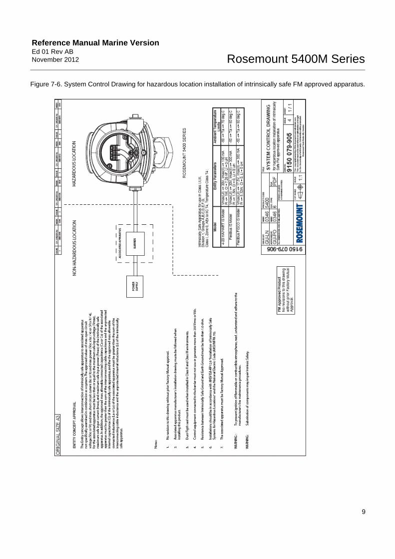
Rosemount Drawing 9150079-905:
System Control Drawing for hazardous location installation of intrinsically safe FM approved apparatus.
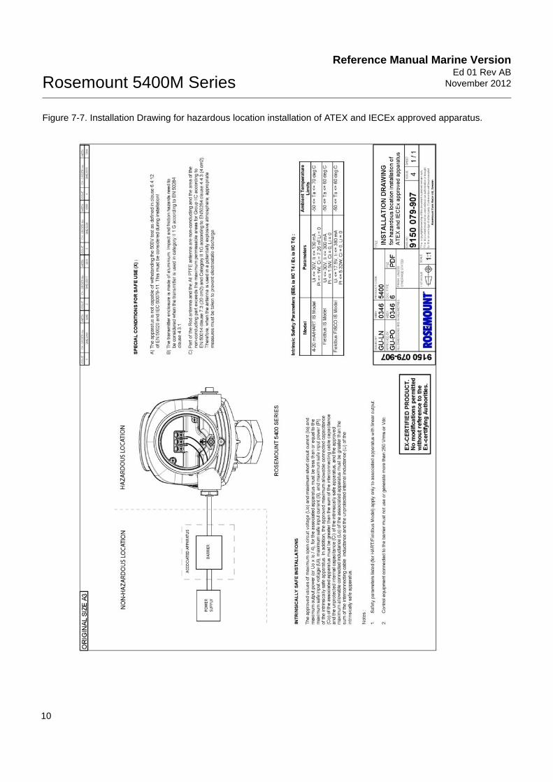
Rosemount Drawing 9150079-907:
Installation Drawing for hazardous location installation of ATEX and IECEx approved apparatus.
Reference Manual Marine Version Ed 01 Rev ABNovember 2012 Rosemount 5400M Series
9
Figure 7-6. System Control Drawing for hazardous location installation of intrinsically safe FM approved apparatus.
Reference Manual Marine VersionEd 01 Rev AB
November 2012Rosemount 5400M Series
10
Figure 7-7. Installation Drawing for hazardous location installation of ATEX and IECEx approved apparatus.

Reference Manual Marine Version Ed 01Rev ABNovember 2012 Rosemount 5400M Series
www.EmersonProcess.com/mtm
IndexAAMS Suit . . . . . . . . . . . . . . . 2-3Analog Output Status . . . . . . . 5-6Antenna . . . . . . . . . . . . . . . . 2-2Approval Drawings . . . . . . . . . 7-8
CCable entry . . . . . . . . . . . . . . 2-2Cable gland . . . . . . . . . . . . . 3-10Cable Protection Hose . . . . . 3-11Cable Selection . . . . . . . . . . . 4-3Cable/conduit entries . . . . . . . 4-2Canadian Standards Association
approval . . . . . . . . . . . . . 7-5system control drawing . 7-10
ComponentsAntenna . . . . . . . . . . . . . 2-2Cable Entry . . . . . . . . . . 2-2Display Panel . . . . . . . . . 2-2Flange . . . . . . . . . . . . . . 2-2Tank Seal . . . . . . . . . . . . 2-2Terminal side . . . . . . . . . 2-2
CPH . . . . . . . . . . . . . . . . . . 3-11
DDiagnostic Messages . . . . . . . 5-3Dielectric constant . . . . . . . . . 2-4Display panel . . . . . . . . . . . . 2-2
EElectrical installation
connecting the transmitter 4-4Intrinsically Safe Output . . 4-6Non-Intrinsically Safe Output 4-5
Errors . . . . . . . . . . . . . . . . . . 5-3European ATEX Directive Information 7-3External circuit breaker . . . . . . 4-3
FFactory Mutual
approval . . . . . . . . . . . . . 7-5system control drawing . . 7-9
Flange . . . . . . . . . . . . . . . . . 2-2Foam . . . . . . . . . . . . . . . . . . 2-4
GGrounding . . . . . . . . . . . . . . 4-3
HHazardous Locations Certifications 7-5
IInstallation
cable selection . . . . . . . . 4-3cable/conduit entries . . . . 4-2grounding . . . . . . . . . . . 4-3placement considerations 3-3power requirements . . . . 4-3procedure . . . . . . . . . . . 3-2
LLoop-powered . . . . . . . . . . . . 2-3
MMarine Application Characteristics 2-4Maximum load resistance .4-5, 4-6Measurement principle . . . . . . 2-1Measurement Status . . . . . . . 5-4Mounting requirements . . . . . 3-3
PPower Requirements . . . . . . . 4-3Product Certifcates . . . . . . . . 7-1
RRosemount 751 . . . . . . . . . . 2-3
SSystem Integration . . . . . . . . 2-3
TTank height . . . . . . . . . . . . . 2-1Tank Seal . . . . . . . . . . . . . . . 2-2Temperature and Pressure Ratings 6-2TGU 51xx
Mounting . . . . . . . . . . . 3-10Theory of Operation . . . . . . . 2-1Transition Zone . . . . . . . . . . . 2-4
Transmitter head . . . . . . . . . .2-2
VVolume Calculation Status . . . .5-5

Reference Manual Marine VersionEd 01 Rev AB
November 2012Rosemount 5400 Series
Index-2


Reference Manual Marine Version Ed 01 Rev ABNovember 2012 Rosemount 5400M Series
© 2012 Rosemount Inc. All rights reserved.
The Emerson logo is a trademark and service mark of Emerson Electric Co. Rosemount and the Rosemount logotype are registered trademarks of Rosemount Inc. The content of this publication are presented for information purposes only, and while efforts have been made to ensure their accuracy, they are not to be construedas warranties or guarantees, expressed or implied, regarding the products or services described herein or their use or applicability. All sales are governed by ourterms and conditions, which are available upon request. We reserve the right to modify or improve the designs or specifications of our products at any time withoutnotice. Rosemount Tank Radar AB accepts no responsibility for any errors that may appear in this publication.
As each system may be configured for each delivery, the content and illustrations in this manual may differ from your system.
Marine Tank ManagementEmerson Process ManagementRosemount Tank Radar ABBox 13045SE-40251 SwedenT +46 31 337 00 00F +46 31 25 30 22www.EmersonProcess.com/mtm