rosemount 2088 absolute and gage pressure transmitter
TRANSCRIPT
Product Data Sheet00813-0100-4690, Rev KBApril 2010 Rosemount 2088
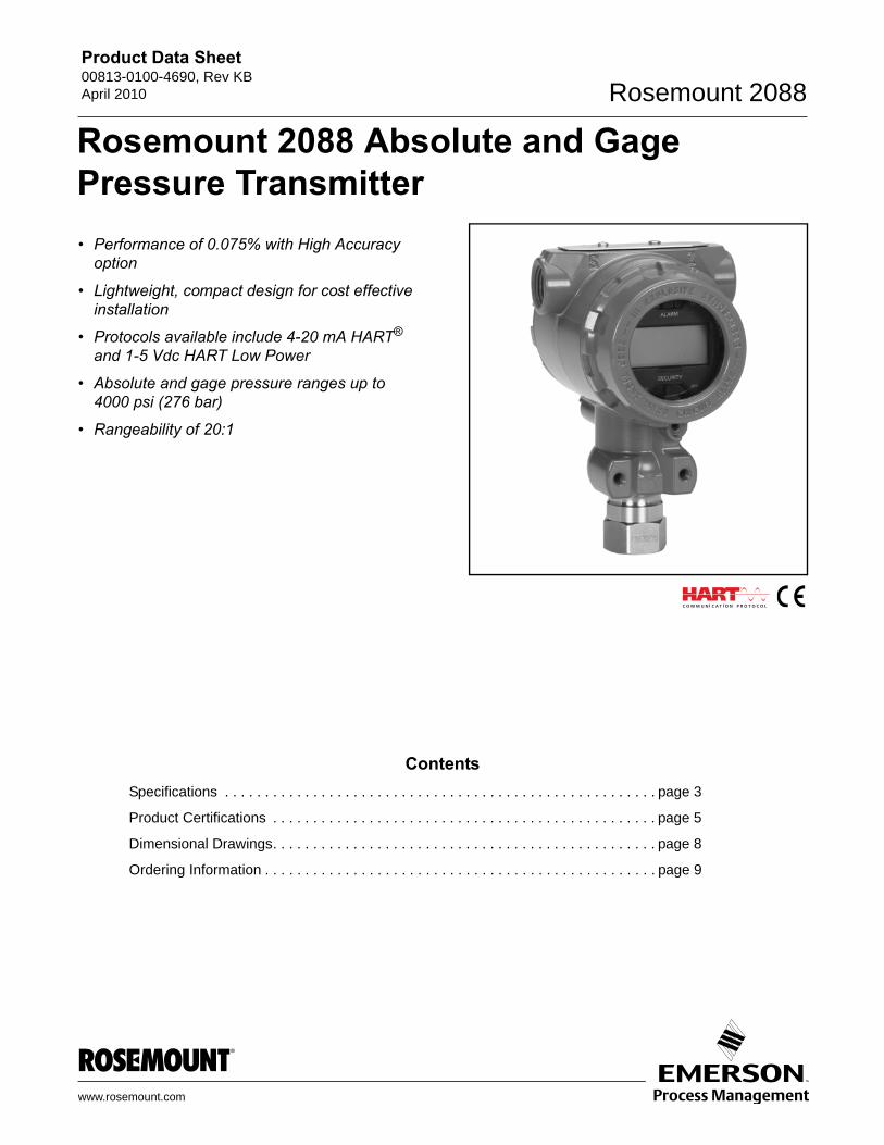
Rosemount 2088 Absolute and Gage Pressure Transmitter
• Performance of 0.075% with High Accuracyoption
• Lightweight, compact design for cost effective installation
• Protocols available include 4-20 mA HART® and 1-5 Vdc HART Low Power
• Absolute and gage pressure ranges up to 4000 psi (276 bar)
• Rangeability of 20:1
www.ro
ContentsSpecifications . . . . . . . . . . . . . . . . . . . . . . . . . . . . . . . . . . . . . . . . . . . . . . . . . . . . . . page 3
Product Certifications . . . . . . . . . . . . . . . . . . . . . . . . . . . . . . . . . . . . . . . . . . . . . . . . page 5
Dimensional Drawings. . . . . . . . . . . . . . . . . . . . . . . . . . . . . . . . . . . . . . . . . . . . . . . . page 8
Ordering Information . . . . . . . . . . . . . . . . . . . . . . . . . . . . . . . . . . . . . . . . . . . . . . . . . page 9
semount.com
Product Data Sheet00813-0100-4690, Rev KB
April 2010Rosemount 2088
Rosemount 2088 Absolute and Gage Pressure Transmitter
Performance of 0.075% with high accuracy option
The Rosemount 2088 utilizes our reliable solid-state, polysilicon pressure sensor with a choice of either 316L or Alloy C-276 isolating diaphragms. This design has many benefits, including a reference accuracy of 0.075% and a stability of 0.10% for 12 months.
Lightweight, Compact Design
Its lightweight, compact design allows the 2088 to be directly connected to a process – providing a quick, easy and cost effective installation. A variety of process connections are available, including multiple threaded connections, our full line of manifolds and remote diaphragm seals that provide solutions for virtually any application.
4-20 mA HART and 1-5Vdc HART Low Power Protocols Available
The 2088 utilizes the advantages of HART communication, enabling quick and easy reranging, calibration and troubleshooting. It also features a fully configurable LCD that displays pressure and diagnostic information. The information displayed is directly from the microprocessor which accounts for its accuracy and reliability.
Absolute or gage pressure ranges up to 4000 psi (276 bar) and 20:1 rangedown
The 2088 is available in either gauge or absolute pressure in ranges to 4,000 psi (276 bar). Higher turndown means lower inventories by allowing you to measure pressures from 1.5 psi (103 mbar) to 4000 psi (276 bar) with only four transmitter ranges.
Rosemount Pressure SolutionsRosemount 3051S Series of InstrumentationHighest performing scalable pressure, flow and level measurement solutions drive better plant efficiency and more productivity. Innovative features include wireless, advanced diagnostics, and multivariable technologies.
Rosemount 305, 306 and 304 ManifoldsFactory-assembled, calibrated and seal-tested transmitter-to-manifold assemblies reduce installation costs.
Rosemount 1199 Diaphragm SealsProvides reliable, remote measurements of process pressure and protects the transmitter from hot, corrosive, or viscous fluids. Orifice Plate Primary Element Systems: Rosemount 1495 and 1595 Orifice Plates, 1496 Flange Unions and 1497 Meter SectionsA comprehensive offering of orifice plates, flange unions and meter sections that are easy to specify and order. The 1595 Conditioning Orifice provides superior performance in tight fit applications.
Rosemount 3051SFA Annubar® Flowmeters and Rosemount 485 Annubar Flowmeter SeriesThe state-of-the-art, fifth generation Rosemount 485 Annubar combined with the Rosemount MultiVariable transmitter technology creates an accurate, repeatable and dependable insertion-type flowmeter.
Rosemount 3051SFC Compact Orifice Flowmeters and Rosemount 405 Compact Orifice Flowmeter SeriesCompact Orifice Flowmeters can be installed between existing flanges, up to a Class 600 (PN100) rating. A conditioning orifice plate version offers installation in tight fit applications requiring only two diameters of straight run upstream after a flow disturbance.
Rosemount 3051SFP Integral Orifice Flowmeters and Rosemount 1195 Integral Orifice Flowmeter SeriesThese integral orifice flowmeters eliminate the inaccuracies that become more pronounced in small orifice line installations. The completely assembled, ready to install flowmeters reduce cost and simplify installation.
2
Product Data Sheet00813-0100-4690, Rev KBApril 2010 Rosemount 2088
Specifications
Performance Specifications(Zero-based spans, reference conditions, silicone oil fill, and 316L SST isolating diaphragm.)
Reference Accuracy• ±0.10% of calibrated span. Includes combined effects of
linearity, hysteresis, and repeatability
• ±0.075% of calibrated span (high accuracy option)
Ambient Temperature EffectExpressed as a total effect per 50 °F (28 °C)Total effect includes zero and span effects.± (0.15% URL + 0.15% of span) from –40 °F to 185 °F(-40 °C to 85 °C)
Stability±0.10% of URL for 12 months
Vibration EffectLess than ±0.1% of URL when subjected to vibration of: peak to peak constant displacement of 4 mm (5–15 Hz) and constant acceleration of 2 g (15–150 Hz) and 1 g (150–2000 Hz).
Power Supply EffectLess than 0.01% of calibrated span per volt
Mounting Position EffectZero shift of up to 1.2 inH2O (0.30 kPa), which can be calibrated out. No span effect.
RFI EffectLess than ±0.25% of upper range limit from20–1000 MHz at 30 V/m with leads in conduit. Less than ±0.25% of upper range limit from 20-1000 MHz at 10 V/m with unshielded twisted pair (no conduit).
Transient Protection Limits
IEEE 587 Category B6 kV Crest (1.2 � 50 �s)3 kA Crest (8 � 20 �s)6 kV Crest (0.5 �s by 100 kHz)
IEEE 472SWC 2.5 kV Crest,1 MHz waveform
General SpecificationsTested to IEC 801-3
Functional Specifications
ServiceLiquid, gas, and vapor applications
Ranges
OutputCode S: 4–20 mA dcCode N: 1-5 volt dc, low power(Outputs are directly proportional to the input pressure)
Rangedown20 to 1
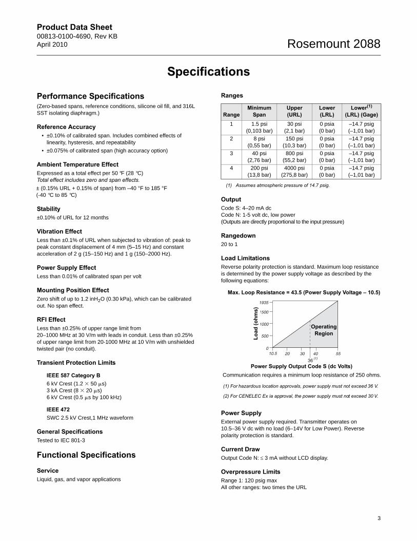
Load LimitationsReverse polarity protection is standard. Maximum loop resistance is determined by the power supply voltage as described by the following equations:
Power SupplyExternal power supply required. Transmitter operates on 10.5–36 V dc with no load (6–14V for Low Power). Reverse polarity protection is standard.
Current DrawOutput Code N: 3 mA without LCD display.
Overpressure LimitsRange 1: 120 psig maxAll other ranges: two times the URL
RangeMinimum
SpanUpper(URL)
Lower (LRL)
Lower(1)
(LRL) (Gage)
(1) Assumes atmospheric pressure of 14.7 psig.
1 1.5 psi(0,103 bar)
30 psi(2,1 bar)
0 psia(0 bar)
–14.7 psig(–1,01 bar)
2 8 psi(0,55 bar)
150 psi(10,3 bar)
0 psia(0 bar)
–14.7 psig(–1,01 bar)
3 40 psi(2,76 bar)
800 psi(55,2 bar)
0 psia(0 bar)
–14.7 psig(–1,01 bar)
4 200 psi(13,8 bar)
4000 psi(275,8 bar)
0 psia(0 bar)
–14.7 psig(–1,01 bar)
Load
(ohm
s)
Operating Region
Power Supply Output Code S (dc Volts)Communication requires a minimum loop resistance of 250 ohms.
(1) For hazardous location approvals, power supply must not exceed 36 V.
(2) For CENELEC Ex ia approval, the power supply must not exceed 30 V.
Max. Loop Resistance = 43.5 (Power Supply Voltage – 10.5)
3
Product Data Sheet00813-0100-4690, Rev KB
April 2010Rosemount 2088
4
Burst Pressure11,000 psi for all ranges
Zero Elevation and SuppressionZero can be suppressed between atmosphere for gage transmitters or 0 psia for absolute transmitters and upper range limit, provided the calibrated span is equal to or greater than the minimum span, and the upper range value does not exceed the upper range limit.
Time ResponseTime Constant: 200 millisecondsDead time: < 0.1 sUpdate rate: 20 times per second minimum
Temperature LimitsAmbient:
Storage:
–50 to 230 °F (–46 to 110 °C)–40 to 185 °F (–40 to 85 °C) with LCD display
Process:
Humidity Limits0–100% relative humidity
Volumetric DisplacementLess than 0.00042 cm3
Turn-on Time2.0 seconds, no warm-up required
Transmitter SecurityActivating the transmitter security function prevents changes to the transmitter configuration, including local zero and span adjustments. Security is activated by an internal switch.
Failure ModeIf self-diagnostics detect a sensor or microprocessor failure, the analog signal is driven either high or low to alert the user. High or low failure mode is user-selectable with a jumper on the transmitter. The values to which the transmitter drives its output in failure mode depend on whether it is factory-configured to standard or NAMUR-compliant operation. The values for each are as follows:
Physical Specifications
Electrical Connection1/2–14 NPT, M20 � 1.5 (CM20), PG 13.5, or G 1/2 female (PF 1/2 female) conduit entry
Process Connection1/2–14 NPT female, DIN 16288 G 1/2 male, RC 1/2 female (PT 1/2 female), M20 � 1.5 (CM20) male
Process Wetted Parts
Isolating Diaphragm316L stainless steel or Alloy C-276
Process Connector316L stainless steel CF-3M (Cast version of 316L SST, material per ASTM_A743) or Alloy C-276
Non-wetted Parts
Electronics HousingLow-copper aluminum, NEMA 4X, IP65, IP67,CSA enclosure Type 4X
PaintPolyurethane
Cover O-ringsBuna-N
Fill FluidSilicone or inert fill
WeightOutput Code S and N: Approximately 2.44 lb (1.11 kg)
TaggingThe transmitter is tagged, at no charge, in accordance with customer requirements. All tags are stainless steel. The standard tag is permanently attached to the transmitter. Tag character height is 1/8 in. (0.318 cm). A wired tag is available upon request.
Accessory Block and Bleed Valve (S5 Option)The Rosemount 306 Integral Manifold is pre-assembled to transmitter and leak checked.
–40 to 185 °F (–40 to 85 °C)–4 to 175 °F (–20 to 80 °C) with LCD display(1)
(1) LCD display may not be readable and LCD updates will be slower at temperatures below -4 °F (-20 °C).
Silicone fill sensor: –40 to 250 °F (–40 to 121 °C)(1)
Inert fill sensor: –22 to 250 °F (–30 to 121 °C)(1)
Process temperatures above 185 °F (85 °C) require derating the ambient limits by a 1.5:1 ratio. For example, for process temperature of 195 °F (91 °C), new ambient temperature limit is equal to 170 °F (77 °C). This can be determined as follows: (195 °F - 185 °F) x 1.5 = 15 °F, 185 °F - 15 °F = 170 °F
(1) 250 °F (140 °C) limit in vacuum service; 130 °F (54 °C) for pressures below 0.5 psia.
Standard Operation
Output Code Linear Output Fail High Fail LowS 3.9 I 20.8 I 21.75 mA I 3.75 mA
N 0.97 V 5.2 V 5.4 V V 0.95V
N with Code C2 0.78 V 3.44 V 4.0 V V 0.77 V
NAMUR-Compliant Operation Linear Output Fail High Fail LowOutput Code S 3.8 I 20.5 I 22.5 mA I 3.6 mA
Product Data Sheet00813-0100-4690, Rev KBApril 2010 Rosemount 2088
Product Certifications
Approved Manufacturing LocationsRosemount Inc. — Chanhassen, Minnesota, USA
Emerson Process Management GmbH & Co. — Wessling, Germany
Emerson Process Management Asia Pacific Private Limited — Singapore
Beijing Rosemount Far East Instrument Co., LTD — Beijing, China
European Union Directive InformationThe EC declaration of conformity for all applicable European directives for this product can be found at www.rosemount.com. A hard copy may be obtained by contacting our local sales office.
ATEX Directive (94/9/EC)Emerson Process Management complies with the ATEX Directive.
European Pressure Equipment Directive (PED) (97/23/EC)2088/2090 Pressure Transmitters— Sound Engineering Practice
Electro Magnetic Compatibility (EMC) (2004/108/EC)All 2088/2090 Pressure Transmitter: EN 61326-1:1997 with Amendments A1, A2, and A3
Hazardous Locations CertificationsNorth American Certifications
Ordinary Location Certification for Factory MutualAs standard, the transmitter has been examined and tested to determine that the design meets basic electrical, mechanical, and fire protection requirements by FM, a nationally recognized testing laboratory (NRTL) as accredited by the Federal Occupational Safety and Health Administration (OSHA).
Factory Mutual (FM) Approvals
E5 Explosion-Proof for Class I, Division 1, Groups B, C, and D. Dust-Ignition-Proof for Class II, Division 1, Groups E, F, G, Class III, Division 1, indoor and outdoor (Type 4X) hazardous locations; factory sealed. Temperature Class T5 Ta = 85 °C.
I5 Intrinsically safe for use in Class I, Division 1, Groups A, B, C, D; Class II, Division 1, Groups E, F, and G; and Class III, Division 1 when connected in accordance with Rosemount drawing 02088-1018. Non-incendive for Class I, Division 2, Groups A, B, C, and D.For input parameters see control drawing 02088-1018. Temperature Class T4 Ta = 85 °C; indoor and outdoor (NEMA 4X) hazardous locations.
Canadian Standards Association (CSA)All CSA hazardous approved transmitters are certified per ANSI/ISA 12.27.01-2003.
C6 Explosion-Proof for Class I, Division 1, Groups B, C, and D. Dust-Ignition-Proof for Class II, Division 1, Groups E, F, G, Class III, indoor and outdoor hazardous locations. CSA enclosure Type 4X; factory sealed. Suitable for Class I, Division 2, Groups A, B, C, and D.
Intrinsically Safe for Class I, Division 1, Groups A, B, C, and D. Temp. Code T3C. Intrinsically safe when connected with approved barriers in accordance with Rosemount drawing 02088-1024. For input parameters see control drawing 02088-1024.
European CertificationsI1 ATEX Intrinsically Safe
Certificate No.: BAS00ATEX1166X II 1 GEx ia IIC T5 (Tamb = –55 to 40 °C)Ex ia IIC T4 (Tamb = –55 to 70°C)
1180
TABLE 1. Input Parameters
Special Conditions For Safe Use (x): When the optional transient protection terminal block is installed, the apparatus is not capable of withstanding a 500V rms test to case. This must be taken into account on any installation in which it is used, for example by assuring that the supply to the apparatus is galvanically isolated.
N1 ATEX Type n Certification No.: BAS00ATEX3167X II 3 GEx nA nL IIC T5 (Ta = -40 °C to 70 °C)Ui = 50 V dc max
Special Conditions For Safe Use (x): When the optional transient protection terminal block is installed, the apparatus is not capable of withstanding a 500 V r.m.s. test to case. This must be taken into account on any installation in which it is used, for example, by assuring that the supply to the apparatus is galvanically isolated.
Loop/PowerUi = 30 V dcIi = 200 mAPi = 0.9 WCi = 0.012 �F
5
Product Data Sheet00813-0100-4690, Rev KB
April 2010Rosemount 2088
ND ATEX Combustible Dust Certificate No.: BAS01ATEX1427X II 1 D Ex tD A20 T105°C (Tamb = -20°C to 85°C)IP66
1180Vmax = 36 V dc MaxIi = 24 mA
Special Conditions For Safe Use (x): 1. The user must ensure that the maximum rated voltage
and current (36 volts, 24 mA, D.C.) are not exceeded. All connections to other apparatus or associated apparatus shall have control over this voltage and current equivalent to a category “ib” circuit according to EN50020.
2. Cable entries must be used which maintain the ingress protection of the enclosure to at least IP66.
3. Unused cable entries must be filled with suitable blanking plugs which maintain the ingress protection of the enclosure to at least IP66.
4. Cable entries and blanking plugs must be suitable for the ambient range of the apparatus and capable of withstanding a 7J impact test.
5. The 2088/2090 sensor module must be securely screwed in place to maintain the ingress protection of the enclosure.
ED ATEX Flameproof Certification No.: KEMA97ATEX2378 II 1/2 GEx d IIC T6 (Ta = -40 °C to 40°C)T4 (Ta = -40 °C to 80 °C)
1180Vmax = 36 (with Output Code S)Vmax = 14 (with Output Code N)
Japanese CertificationsE4 TIIS Flameproof
Ex d IIC T6 (Tamb = 85 °C)
Australian CertificationsI7 SAA Intrinsic Safety
Certification No.: AUS Ex 1249XEx ia IIC T4 (Tamb = 70 °C)Ex ia IIC T5 (Tamb = 40 °C)IP66When connected per Rosemount drawing 03031-1026
Special Conditions For Safe Use (X):Observe barrier/entity parameters during installation. A passive current limited power source must be used. The power source must be such that Po (Uo * Io)/4. For modules using transient protection in the terminal assembly (T1 transient protection models), the apparatus enclosure is to be electrically bonded to the protective earth. The conductor used for the connection shall be equivalent to a copper conductor of 4mm2 minimum cross-sectional area.
N7 SAA Type n (Non-Sparking)Certificate No.: AUS Ex 1249XEx n IIC T4 (Tamb = 70 °C)Ex n IIC T5 (Tamb = 40 °C)IP66
Special Conditions For Safe Use (X):Where the equipment is installed such that there is an unused conduit entry, it must be sealed with a suitable blanking plug to maintain the IP66 degree of protection. Any blanking plug used with the equipment shall be of a type which requires the use of a tool to effect its removal. Voltage source shall not exceed 60V ac or 75V dc.
E7 IECEx Flameproof (Explosion-Proof)IECEx Certificate number: IECEx KEM 06.0021XEx d IIC T6(Tamb = -20°C to 40°C)Ex d IIC T4(Tamb = -20°C to 80°C)Vmax = 55VdcIi = 23mA
Certificate DescriptionTC15879 2088 with SST wetted parts
(with display)TC15877 2088 with Alloy C-276 wetted parts
(with display)TC15876 2088 with Alloy C-276 wetted parts
(no display)TC15875 2088 with SST wetted parts
(no display)TC15874 2088 with Alloy C-276 wetted parts
(with display)TC15873 2088 with Alloy C-276 wetted parts
(no display)TC15872 2088 with SST wetted parts
(with display)TC15871 2088 with SST wetted parts
(no display)
TABLE 2. Input Parameters
Loop/PowerUmax = 30 V
Imax = 200 mA
Pmax = 0.9 W
Ci = 0.01 �F
Li = 10 �H
6
Product Data Sheet00813-0100-4690, Rev KBApril 2010 Rosemount 2088
NK IECEx Dust Ignition ProofIECEx Certificate number: IECEx KEM 06.0021XEx tD A22 IP66 T90°C(Tamb = -20°C to 80°C)Vmax = 55VdcIi = 23mA
Special Conditions For Safe Use (x):
1. The device contains a thin wall diaphragm. Installation, maintenance, and use shall take into account the environmental conditions to which the diaphragm will be subjected. The manufacturer’s instructions for installation and maintenance shall be followed in detail to assure safety during its expected lifetime.
2. Cable entries must be used which maintain the ingress protection of the enclosure to at least IP 66.
3. Unused cable entries must be used which maintain the ingress protection of the enclosure to at least IP 66.
4. Cable entries and blanking plugs must be suitable for the ambient range of the apparatus and capable of withstanding a 7J impact.
5. The 2088/2090 sensor module must be securely screwed in place to maintain the ingress protection of the enclosure
Brazil CertificationsI2 INMETRO Intrinsic Safety
Certification No.: CEPEL-Ex-063/97-1XBR-Ex ia IIC T5/T4
E2 INMETRO FlameproofCertification No.: CEPEL-Ex-076/97-1BR-Ex d IIC T6/T5
Combinations of CertificationsStainless steel certification tag is provided when optional approval is specified. Once a device labeled with multiple approval types is installed, it should not be reinstalled using any other approval types. Permanently mark the approval label to distinguish it from unused approval types.
KB Combination of K5 and C6
KH Combination of K5, I1, and ED
K5 Combination of E5 and I5
K6 Combination of C6, I1, and ED
K7 Combination of I7, N7, E7, and NK
K1 Combination of I1, N1, ED, and ND
7
Product Data Sheet00813-0100-4690, Rev KB
April 2010Rosemount 2088
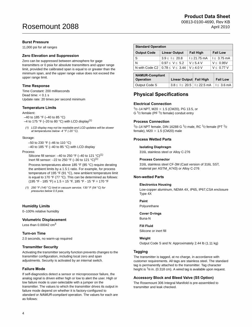
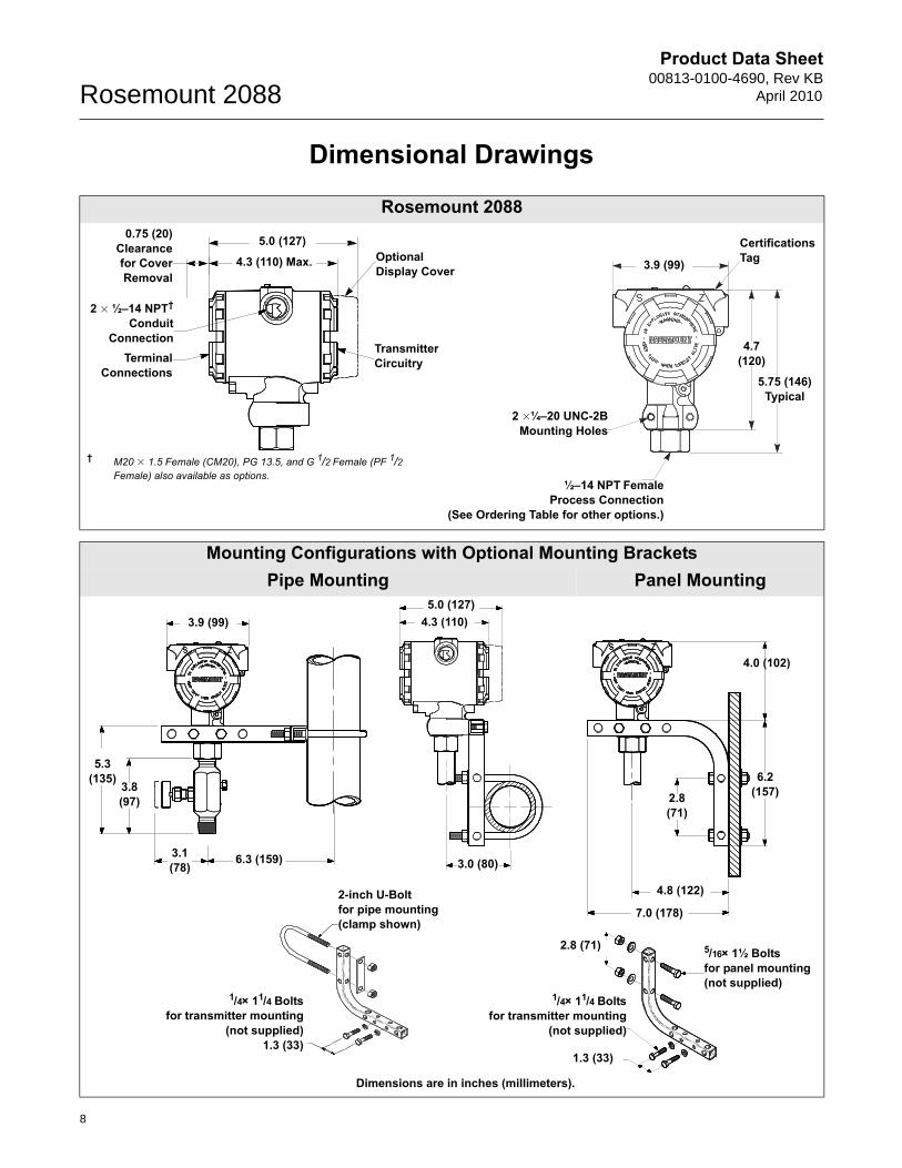
Dimensional Drawings
Rosemount 2088
Mounting Configurations with Optional Mounting BracketsPipe Mounting Panel Mounting
2 � ½–14 NPT†
ConduitConnection
Terminal Connections
5.0 (127)OptionalDisplay Cover
TransmitterCircuitry
4.3 (110) Max.
0.75 (20)Clearancefor CoverRemoval
Certifications Tag
2 �¼–20 UNC-2BMounting Holes
½–14 NPT FemaleProcess Connection
(See Ordering Table for other options.)
3.9 (99)
5.75 (146)Typical
4.7 (120)
† M20 � 1.5 Female (CM20), PG 13.5, and G 1/2 Female (PF 1/2 Female) also available as options.
6.3 (159)3.1 (78)
3.8(97)
5.3(135)
3.0 (80)
4.0 (102)
6.2(157)2.8
(71)
4.8 (122)
7.0 (178)2-inch U-Boltfor pipe mounting(clamp shown)
1.3 (33)
2.8 (71) 5/16× 1½ Boltsfor panel mounting(not supplied)
1/4× 11/4 Boltsfor transmitter mounting
(not supplied)
Dimensions are in inches (millimeters).
3.9 (99)5.0 (127)
4.3 (110)
1/4× 11/4 Boltsfor transmitter mounting
(not supplied)1.3 (33)
8
Product Data Sheet00813-0100-4690, Rev KBApril 2010 Rosemount 2088
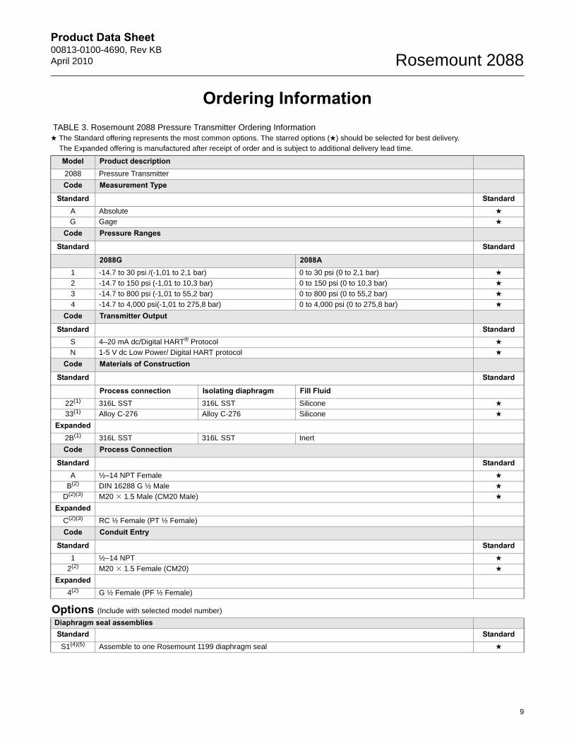
Ordering Information TABLE 3. Rosemount 2088 Pressure Transmitter Ordering Information★ The Standard offering represents the most common options. The starred options (★) should be selected for best delivery.__The Expanded offering is manufactured after receipt of order and is subject to additional delivery lead time.
Model Product description2088 Pressure Transmitter
Code Measurement Type
Standard StandardA Absolute ★
G Gage ★
Code Pressure Ranges
Standard Standard
2088G 2088A1 -14.7 to 30 psi /(-1,01 to 2,1 bar) 0 to 30 psi (0 to 2,1 bar) ★
2 -14.7 to 150 psi (-1,01 to 10,3 bar) 0 to 150 psi (0 to 10,3 bar) ★
3 -14.7 to 800 psi (-1,01 to 55,2 bar) 0 to 800 psi (0 to 55,2 bar) ★
4 -14.7 to 4,000 psi(-1,01 to 275,8 bar) 0 to 4,000 psi (0 to 275,8 bar) ★
Code Transmitter Output
Standard StandardS 4–20 mA dc/Digital HART® Protocol ★
N 1-5 V dc Low Power/ Digital HART protocol ★
Code Materials of Construction
Standard Standard
Process connection Isolating diaphragm Fill Fluid22(1) 316L SST 316L SST Silicone ★
33(1) Alloy C-276 Alloy C-276 Silicone ★
Expanded2B(1) 316L SST 316L SST Inert
Code Process Connection
Standard StandardA ½–14 NPT Female ★
B(2) DIN 16288 G ½ Male ★
D(2)(3) M20 � 1.5 Male (CM20 Male) ★
ExpandedC(2)(3) RC ½ Female (PT ½ Female)
Code Conduit Entry
Standard Standard1 ½–14 NPT ★
2(2) M20 � 1.5 Female (CM20) ★
Expanded4(2) G ½ Female (PF ½ Female)
Options (Include with selected model number)
Diaphragm seal assembliesStandard Standard
S1(4)(5) Assemble to one Rosemount 1199 diaphragm seal ★
9
Product Data Sheet00813-0100-4690, Rev KB
April 2010Rosemount 2088
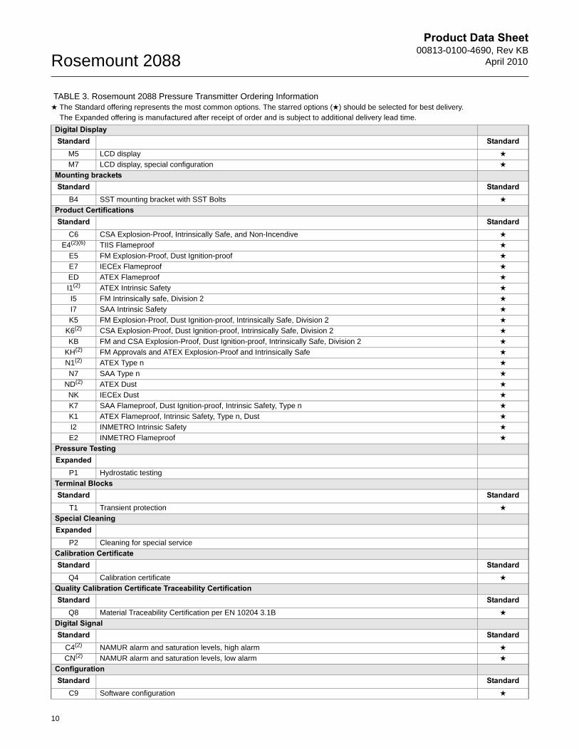
Digital DisplayStandard Standard
M5 LCD display ★
M7 LCD display, special configuration ★
Mounting bracketsStandard Standard
B4 SST mounting bracket with SST Bolts ★
Product CertificationsStandard Standard
C6 CSA Explosion-Proof, Intrinsically Safe, and Non-Incendive ★
E4(2)(6) TIIS Flameproof ★
E5 FM Explosion-Proof, Dust Ignition-proof ★
E7 IECEx Flameproof ★
ED ATEX Flameproof ★
I1(2) ATEX Intrinsic Safety ★
I5 FM Intrinsically safe, Division 2 ★
I7 SAA Intrinsic Safety ★
K5 FM Explosion-Proof, Dust Ignition-proof, Intrinsically Safe, Division 2 ★
K6(2) CSA Explosion-Proof, Dust Ignition-proof, Intrinsically Safe, Division 2 ★
KB FM and CSA Explosion-Proof, Dust Ignition-proof, Intrinsically Safe, Division 2 ★
KH(2) FM Approvals and ATEX Explosion-Proof and Intrinsically Safe ★
N1(2) ATEX Type n ★
N7 SAA Type n ★
ND(2) ATEX Dust ★
NK IECEx Dust ★
K7 SAA Flameproof, Dust Ignition-proof, Intrinsic Safety, Type n ★
K1 ATEX Flameproof, Intrinsic Safety, Type n, Dust ★
I2 INMETRO Intrinsic Safety ★
E2 INMETRO Flameproof ★
Pressure TestingExpanded
P1 Hydrostatic testing
Terminal BlocksStandard Standard
T1 Transient protection ★
Special CleaningExpanded
P2 Cleaning for special service
Calibration CertificateStandard Standard
Q4 Calibration certificate ★
Quality Calibration Certificate Traceability CertificationStandard Standard
Q8 Material Traceability Certification per EN 10204 3.1B ★
Digital Signal Standard Standard
C4(2) NAMUR alarm and saturation levels, high alarm ★
CN(2) NAMUR alarm and saturation levels, low alarm ★
ConfigurationStandard Standard
C9 Software configuration ★
TABLE 3. Rosemount 2088 Pressure Transmitter Ordering Information★ The Standard offering represents the most common options. The starred options (★) should be selected for best delivery.__The Expanded offering is manufactured after receipt of order and is subject to additional delivery lead time.
10
Product Data Sheet00813-0100-4690, Rev KBApril 2010 Rosemount 2088
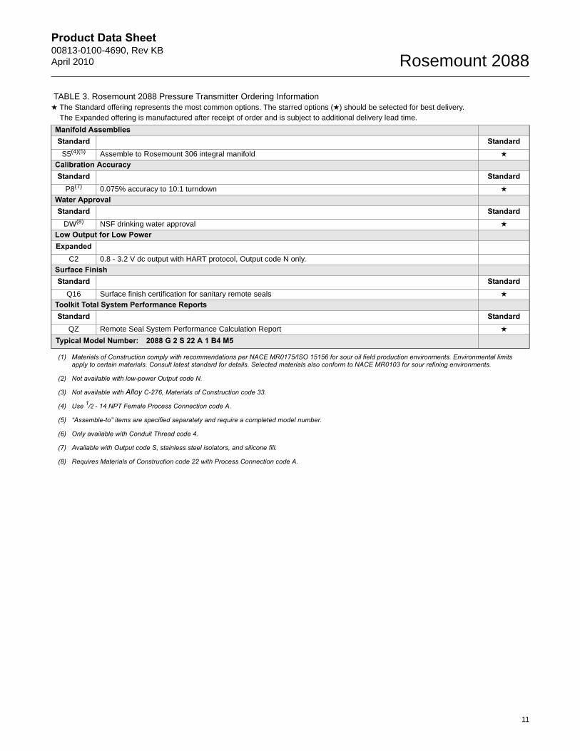
Manifold AssembliesStandard Standard
S5(4)(5) Assemble to Rosemount 306 integral manifold ★
Calibration AccuracyStandard Standard
P8(7) 0.075% accuracy to 10:1 turndown ★
Water ApprovalStandard Standard
DW(8) NSF drinking water approval ★
Low Output for Low PowerExpanded
C2 0.8 - 3.2 V dc output with HART protocol, Output code N only.
Surface FinishStandard Standard
Q16 Surface finish certification for sanitary remote seals ★
Toolkit Total System Performance ReportsStandard Standard
QZ Remote Seal System Performance Calculation Report ★
Typical Model Number: 2088 G 2 S 22 A 1 B4 M5
(1) Materials of Construction comply with recommendations per NACE MR0175/ISO 15156 for sour oil field production environments. Environmental limits apply to certain materials. Consult latest standard for details. Selected materials also conform to NACE MR0103 for sour refining environments.
(2) Not available with low-power Output code N.
(3) Not available with Alloy C-276, Materials of Construction code 33.
(4) Use 1/2 - 14 NPT Female Process Connection code A.
(5) “Assemble-to” items are specified separately and require a completed model number.
(6) Only available with Conduit Thread code 4.
(7) Available with Output code S, stainless steel isolators, and silicone fill.
(8) Requires Materials of Construction code 22 with Process Connection code A.
TABLE 3. Rosemount 2088 Pressure Transmitter Ordering Information★ The Standard offering represents the most common options. The starred options (★) should be selected for best delivery.__The Expanded offering is manufactured after receipt of order and is subject to additional delivery lead time.
11
Product Data Sheet00813-0100-4690, Rev KB
April 2010Rosemount 2088
Standard Terms and Conditions of Sale can be found at www.rosemount.com\terms_of_saleThe Emerson logo is a trade mark and service mark of Emerson Electric Co. Rosemount, the Rosemount logotype, Annubar, ProPlate and Mass ProPlate are registered trademarks of Rosemount Inc.HART is a registered trademark of the HART Communications Foundation.PlantWeb is a registered trademark of one of the Emerson Process Management group of companies.All other marks are the property of their respective owners.© 2010 Rosemount, Inc. All rights reserved.
00813-0100-4690 Rev KB, 4/10
Emerson Process Management Blegistrasse 23P.O. Box 1046CH 6341 BaarSwitzerlandTel +41 (0) 41 768 6111Fax +41 (0) 41 768 6300
Emerson Process Management Asia Pacific Pte Ltd1 Pandan CrescentSingapore 128461Tel +65 6777 8211Fax +65 6777 0947Service Support Hotline : +65 6770 8711Email : [email protected]
Emerson Process ManagementRosemount Measurement8200 Market BoulevardChanhassen MN 55317 USATel (USA) 1 800 999 9307Tel (International) +1 952 906 8888Fax +1 952 949 7001
Emerson FZEP.O. Box 17033Jebel Ali Free ZoneDubai UAETel +971 4 811 8100Fax +971 4 886 5465