room air conditioner owner’s manual for - the home depot · pdf fileroom air conditioner...
TRANSCRIPT

517.787.2100 • www.marsdelivers.com • www.heatcontroller.com
Room Air ConditionerOwner’s Manual for:
RADS-101PRADS-121PRADS-123P
Table of Contents Important Safety Instructions ..........................................................................1-3 Installation Instructions .................................................................................4-11 Normal Sounds ................................................................................................12 Air Conditioner Features ............................................................................ 12-14 Care and Cleaning ..................................................................................... 14-15 Troubleshooting Tips ................................................................................. 15-16 Limited Express Warranty ................................................................................17
Before using your air conditioner, please read
this manual carefully and keep it for future reference.
WINDOW/WALL TYPEROOM AIR CONDITIONER
-
MULTI-STEP SPEED ELECTRONIC CONTROL
TABLE OF CONTENTS
Installation Instructions
................................................12
4-11
Normal Sounds
.......................................................................
Important Safety Instructions ..........................1-3
Troubleshooting Tip 15-16.....................................
Air Conditioner Features 12-14.............................
Care and Cleaning 14-15

Owner’s Manual - RADS-101P, RADS-121P, RADS-123P
1
IMPORTANT SAFETY INSTRUCTIONS
Inside you will find many helpful hints on how to use and maintain your air conditionerproperly. Just a little preventive care on your part can save you a great deal of time and money over the life of your air conditioner. You'll find many answers to common problems in the chart of troubleshooting tips. If you review our chart of Troubleshooting Tips first, you may not need to call for service at all.
To prevent injury to the user or other people and property damage, the following
instructions must be followed. Incorrect operation due to ignoring of instructions may
cause harm or damage. The seriousness is classified by the following indications.
This symbol indicates the possibility of death or serious injury.
Always do this.Never do this.
CAUTION This symbol indicates the possibility of injury or damage to property.
WARNING
WARNING
Plug in power plug properly.
Do not modify power cord length or share the outlet with other appliances.
Always ensure effectivegrounding.
Unplug the unit if strange sounds, smell, or smoke come from it.
Keep firearms away.
Ventilate room before operating air conditioner if there is a gas leakage from another appliance.
Otherwise, it may cause electric shock or fire due to excess heat generation.
It may cause electric shock or fire due to heat generation. Incorrect grounding may cause electric shock.
It may cause fire and electric shock.
It may cause fire.
It may cause explosion, fire and, burns.
It may cause electric shock or fire due to heat generation.
It may cause electric shock.
It may cause failure of machine or electric shock.
It may cause fire and electric shock.
It may cause fire and electric shock.
It may cause electric shock or fire. If the power cord is damaged, it must be replaced by the manufacturer or an authorized service center or a similarly qualified person in order to avoid a hazard.
This could damage your health. Incorrect installation may cause fire and electric shock.
It may cause electric shock.
It may cause an explosion or fire.
It may cause failure and electric shock.
Do not operate or stop theunit by inserting or pulling out the power plug.
Do not operate with wethands or in damp environment.
Do not allow water to runinto electric parts.
Do not use the socket if it isloose or damaged.
Do not use the power cordclose to heating appliances.
Do not damage or use an unspecified power cord.
Do not direct airflow at room occupants.Always install circuit breaker and a dedicatedpower circuit.
Do not open the unit during operation.
Do not use the power cord near flammable gas or combustibles, such as gasoline, benzene, thinner, etc.
Do not disassemble or modify unit.
!
!
!
!
!
!
! !
READ THIS MANUAL
1

Owner’s Manual - RADS-101P, RADS-121P, RADS-123P
2
When the air filter is to be removed, do not touch the metal parts of the unit.
It may cause an injury.
Do not clean unit when power is on as it may c ause fi re an d el ectric sh ock,it may cause an injury.
Operation with windows opened may cause wetting of indoor and soaking of household furniture.
When the unit is to be cleaned, switch off, and turn off the circuit breaker.
Use caution when unpacking and installing. Sharp edges could cause injury.
Do not clean the air conditioner with water.
Water may enter the unit and degrade the insulation. It may cause an electric shock.
This could injure the pet or plant.
It may cause electric shock and damage.
Do not put a pet or house plant where it will be exposed to direct air flow.
Ventilate the room well whenused together with a stove, etc.
An oxygen shortage may occur.
Do not use this air conditioner to preserve precision devices, food,pets, plants, and art objects.It may cause deterioration of quality, etc.
It may cause failure of product or fire.
Do not use for special purposes.
If water enters the unit, turn the unit off at the power outlet and switch off the circuit breaker. Isolate supply by taking the power-plug out and contact a qualified service technician.
!
!
! !
It may cause failure of appliance or accident.
Appearance may be deteriorated due to change of product color or scratching of its surface.
If bracket is damaged, there is concern of damage due to falling of unit.
There is danger of fire or electric shock.
Operation without filters may cause failure.
It contains contaminants and could make you sick.
Stop operation and close the window in storm or hurricane.
!
Do not use strong detergent such as wax or thinner but use a soft cloth.
Ensure that the installation bracket of the outdoor appliance is not damaged due to prolonged exposure.
Hold the plug by the head of the power plug when taking it out.
! Turn off the main power switch when not using theunit for a long time.
!
! !
Always insert the filters securely. Clean filter once every t wo w eeks.
!
Do not place heavy object on the powercord and ensure that the cord is not compressed.
Do not drink water drained from air conditioner.
This appliance is not intended for use by persons (including children) with reduced physical ,sensory or mental capabilities or lack of experience and knowledge, unless t hey h aveb eengi ven su pervision or instruction concerning use of the appliance by a person responsible for their safety. Children should be supervised to ensure that they do not play with the appliance. If the supply cord is damaged, it must be replaced by the manufacturer, its service agent or similarly qualified persons in order to avoid a hazard.
CAUTION
2
CAUTION
Do not place obstacles around air-inlets or inside of air-outlet.
The appliance shall be installed in accordance with national wiring regulations. Do not operate your air conditioner in a wet room
such as a bathroom or laundry room. Any appliance with electric heater shall have at l east 1 meter s pace to combustible materials. Contact an authorized service technician for repair or maintenance of this unit. Contact an authorized installer for installation of this unit.
IMPORTANT SAFETY INSTRUCTIONS
• This appliance is not intended for use by persons (including children) with reduced physical ,sensory or mental capabilities or lack of experience and knowledge, unless they have been given supervision or instruction concerning use of the appliance by a person responsible for their safety.
• Children should be supervised to ensure that they do not play with this appliance.
• If the supply cord is damaged, it must be replaced by the manufacturer, its service agent or similarly qualified persons in order to avoid a hazard.
• This appliance shall be installed in accordance with national wiring regulations
• Do not operate your air conditioner in a wet room such as a bathroom or laundry room.
• Any appliance with electric heater shall have at least 1 meter s pace to combustible materials.
• Contact an authorized service technician for repair or maintenance of this unit.
• Contact an authorized installer for installation of this unit.

Owner’s Manual - RADS-101P, RADS-121P, RADS-123P
3
Do not, under anycircumstances, cut,remove, or bypassthe grounding prong.
Power supply cordwith 3-prong grounding plugand current detection device
Grounding type wallreceptacle
WARNING
NOTE:
The power supply cord with this air
conditioner contains a current detection
device designed to reduce the risk of fire.
Please refer to the section Operation
of Current Device for details.In the event
that the power supply cord is damaged,
it cannot be repaired-it must be replaced
with a c ord f rom t he P roduct M anufacturer.
Avoid fire hazard or electric shock. Do notuse an extension cord or an adaptor plug. Do not remove any prong from the power cord.
WARNING
For Your Safety
WARNING
Prevent Accidents
WARNING
Electrical Information
Do not store or use gasoline or other flammable vapors and liquids in the vicinity of this or any other appliance.
Operation of Current Device(Applicable to unit with current detection device only )
The power supply cord contains a current device that senses damage to the power cord. To test your power supply cord do the following:1. Plug in the Air Conditioner.2. The power supply cord will have TWO buttons on the plug head. Press the TEST button, you will notice a click as the RESET button pops out.3. Press the RESET button, again you will notice a click as the button engages.4. The power supply cord is now supplying electricity to the unit. (On some products this it also indicated by a light on the plug head.)
3
To reduce the risk of fire, electrical shock, or injury to persons when using yourair conditioner, follow basic precautions, including the following: Be sure the electrical service is adequate for the model you have chosen. This information can be found on the serial plate, which is located on the side of the the cabinet and behind the grille. If the air conditioner i s t o b e in stalled in a w indow, yo u w ill pr obably w ant to cl ean both sides of the g lass f irst. I f th e w indow is a tri ple-track ty pe w ith a sc reen pa nel included, remove the screen completely before installation. Be sure the air c onditioner h as b een s ecurely a nd c orrectly in stalled a ccording to the installation instructions in this manual. Save this manual for possible future use in removing or installing this unit. When handling the air conditioner, be careful to avoid cuts f rom s harp m etal f ins on front and rear coils.
The complete electrical rating of your new room air conditioner is stated on the serial plate. Refer to the rating when checking the electrical requirements. Be sure the air conditioner is properly grounded. To minimize shock and fire hazards, proper grounding is important. The power cord is equipped with a three-prong grounding plug for protection against shock hazards. Your air conditioner must be used in a properly grounded wall receptacle. If the wall receptacle you intend to use is not adequately grounded or protected by a time delay fuse or circuit breaker, have a qualified electrician install the proper receptacle. Ensure the receptacle is accessible after the unit installation. Do not run air conditioner without side protective cover in place.This could result in mechanical damage within the air conditioner. Do not use an extension cord or an adapter plug.
IMPORTANT SAFETY INSTRUCTIONS
Do not use this device to turn the unit on or off. Always make sure the RESET button is pushed in for correct operation. The power supply must be replaced if it fails reset when either the TEST button is pushed, or it cannot be reset. A new one can be obtained from the product manufacturer. If power supply cord is damaged, it cannot be repaired. It MUST be replaced by one obtained from the product manufacturer.
NOTE:
NOTE:This air conditioner is designed to be operated
under condition as follows:
Cooling
operation
Outdoor temp:
Indoor temp:
Heating
operation
Outdoor temp: OO23-76 F/ C-5-24
Indoor temp: O32-80 F/
O
0-27 C
O O O O64-109 F/18-43 C (64-125 F/18-52 C
for special tropical models)O
62-90 F/O
17-32 C
Note: Performance may be reduced outside of these operating temperatures.

Owner’s Manual - RADS-101P, RADS-121P, RADS-123P
4
4
INSTALLATION INSTRUCTIONS
Read these instructions completely and carefully.
IMPORTANT- Save theseinstructions for local inspector s use.
IMPORTANT- Observe allgoverning codes and ordinances.
Note to Consumer- Keep theseinstructions for future reference.
Note to Installer- Be sure to leave theseinstructions with the Consumer.
Completion time- Approximately 1 hour.
Skill level- Installation of this appliancerequires basic mechanical skills.
We recommend that two people installthis product.Proper installation is the responsibilityof the installer.Product failure due to improper installationis not covered under the Warranty.You MUST use all supplied parts and useproper installation procedures as describedin these instructions when installing this airconditioner.
BEFORE YOU BEGIN
Do not, under any circumstances, cut orremove the third (ground) prong from thepower cord.
CAUTION
Do not change the plug on the power cordof the air conditioner.
Aluminum house wiring may present specialproblems- consult a qualified electircian.
When handling unit, be careful to avoid cuts fromsharp metal edges and aluminum fins on front andrear coils.
Save Carton and these Installation Instructionsfor future reference. The carton is the best wayto store unit during winter, or when not in use.
NOTE:
Preliminary Instructions
Do the following before starting to install unit. See illustrations below.Check dimensions of your unit to determine model type: Unit Height: 18 5/8 17 5/8 Unit Width:Min. Window Opening:Min. Window Width:Max. Window Width:
26 2312/ 5
8/19 181
2/31 2842 401
2/
1. Check window opening size-- the mounting parts furnished with this air conditioner are made to install in a wooden sill double-hung window. The standard parts are for window dimensions listed above. Open sash to a mini- mum of 19 inches(483mm). See Fig.D.
SASH
/2 MIN.1
19 MIN.
Storm Window Frame orOther Obstruction
Storm Window Frame or Other Obstruction
Board ThicknessAs Required,Along Entire Stool. FastenWith Two NailsOr Screws.
Fig.D Fig.E
/2 MIN.1 /2 MIN.1
19 MIN.
SASH
Window Sash Seal
Safety Lock and3 /4 (or1/2 ) Long Hex Head Screw
Top AngleFoam Gasket
Washer HeadLocking screw
Frame Assembly(Left)
Side Retainer
Bottom railseal to Unit 1 /2 Long
Screw andLocknuts
Locknut
3 /4 LongFlat HeadBolt Sill Angle
Bracket
Window SupportBracket
Frame Assembly(Right)
1/2
2.Check condition of window-- all wood parts of window must be in good shape and able to firmly hold the needed screws. If not, make repairs before installing unit.

Owner’s Manual - RADS-101P, RADS-121P, RADS-123P
55
INSTALLATION INSTRUCTIONS
3. Check your storm windows-- if your storm window frame does not allow the clearance required, correct by adding a piece of wood as shown in Fig. E,or by removing storm window while room air conditioner is being installed.
4 .Check for anything that could block airflow-- check area outside of window for things such as shrubs, trees, or awnings. Inside, be sure furniture, drapes, or blinds will not stop proper airflow. 5.Check the available electrical service- Power supply must be the same as that shown on the unit serial nameplate. Power cord is 48 inches long. Be sure you have an outlet near. 6.Carefully unpack air conditioner- Remove all packing material. Protect floor or carpet from damage. Two people should be used to move and install unit.
Preliminary Instructions A.Window Mounting1 Remove Chassis
1. Pull down front grille and remove filter. (See Fig.1).2. Lift front grille upwards and place to one side.
3. Locate the four front screws and remove. These screws will be needed to re-install the front panel (see Fig.2).
7. Remove shipping screws from top of unit and also on the side by the base if installed (see Fig.5).8. Hold the cabinet while pulling on the base pan handle, and carefully remove the unit.9. Add two foam inserts to holes in top of cabinet where shipping screws were removed (see Fig.6).
4. Push metal cabinet side to release plastic tabs on each side of front panel (see Fig.3).5. Gently lift front panel off unit(see Fig.3A).6. Disconnect the connector plug of the display panel from the unit and place front panel to one side(see Fig.4).
Front Grille
Fig.1 Fig.2
Fig.3
Fig.3A
Front Panel
Fig.4
shippingscrews
Fig.5 Fig.6
Tools RequiredA large flat blade screwdriver;Tape measureAdjustable wrench or pliers;Pencil;LevelSocket wrenches;Phillips Screwdriver
Hardware(Packed with the unit)
7/16 inch Lockingscrew and Flat washer for windowpanels
3 / 4 £or 1/2)inch Long Hex-head Screw
Safety Lock
1 / 2 inch Longscrew and Locknut
3 / 4 inch LongFlat Head Bolt and Locknut
Sill Angle Bracket
Long hex-headlocking screw for top angle, side retainer 5 /16 inch Long
2 ea.
7
1
4ea.
2ea.
2
10
Foam insert 2
Window sash seal foam 1
R1 hardware 2
(10 *3/4 *1/12 ) NOET: R1 hardware and Weather stripping is only
for Energy star models.
Weather stripping5

Owner’s Manual - RADS-101P, RADS-121P, RADS-123P
6
6
INSTALLATION INSTRUCTIONS
10. Your unit may come with internal packaging. This packaging must be removed prior to installing the air conditioner back into the cabinet.(see Fig.7).
2 Install Top Angle and
Side Bracket
1. Attach foam gasket to top angle above holes as shown in Fig.6.2. Install top angle and side retainers to cabinet as shown in Fig.8 (10 sc- rews).
3 Assemble Window Filler Panels
1. Place cabinet on floor, a bench, or a table.2. Slide I section of window filler panel into side retainer on the side of the cabinet (see Fig.9 & Fig.10). Do both sides.
,,,,
PlasticFrame
Window FillerPanel
Side RetainerFig.9
5 16 longhex-head
/
Shipping Packaging
Plastic tie
Fig.7
Fig.8
3. Insert top and bottom legs of window filler panel frame into channel in the top angle and bottom rail. Do both sides.4. Insert washer head locking 7/16" screws (2) into holes in top leg of filler panel frame (see step 6). Do not totally tigh- ten. Allow leg to slide freely. Screws will be tightened after section 6.
4 Place Cabinet in1.Open window and mark center of window stool as shown(Fig.11).2. Place cabinet in window with bottom stool angle firmly seated over window stool as shown. Bring window down temporarily behind top angle to hold cabinet in place(Fig.12).
Stool
StoolAngle
TopView
Air ConditionerCabinet
PlasticFrame
"¢" SectionWindowFillerPanel
LockingScrewHole
Fig.10
Fig.11
Fig.12
3. Shift cabinet left or right as needed to line up center of cabinet on center line marked on stool.4. Fasten cabinet to window stool with 2 screws into holes(You may wish to pre-drill pilot holes).5. Add bottom rail seal over screws to window stool.

Owner’s Manual - RADS-101P, RADS-121P, RADS-123P
7
7
INSTALLATION INSTRUCTIONS
5 Install Support Bracket
1. Hold each support bracket flush against outside of sill, and tight to bottom of cabinet as shown in Fig.15A. Mark brackets at top level of sill, and remove.2. Assemble sill angle bracket to support brackets at the marked position(Fig.15B). Hand tighten, but allow for any changes later.
BottomRail Seal
1 2 Long ScrewsAnd LocknutsLeft
RightSill AngleBracket
Flat Head Bolt
2 Each Required For Each Support Bracket
Locknut
3 4 (or1 )LongHex-head Screw
/2
Fig.13
Fig.15A
Mark
Fig.15B
3. Close window behind top angle.
6 Extend Window Filler Panels
1. Carefully raise window to expose filler panel locking screws. Loosen screws so filler panels slide easily.2. Extend panels to fill window opening completely. Tighten locking screws on top(Fig.17).
3. Install support brackets(with sill angle brackets attached) to correct hole in bottom of cabinet as shown in Fig.16.4. Tighten all 6 bolts securely.
1 2 Long Screws and Locknuts
Locking Screw
7/16"Locking Screw and Washer
Fig.16
Fig.17
FIG.145
Side Louvers
Window Sash
Window Sill
Sill Angle Bracket
1 5About1 / to1 /4 8
Measure fromthe cabinet edge.
NOTE: Check that air conditioner is tilted back about1 5 O O 1 / to 1 / (tilted about 3 t o 4 downward t o th e o utside).4 8
After proper installation, condensate should not drain from the overflow drain h ole d uringn ormalu se,c orrect the slope otherwise (Fig.14).

Owner’s Manual - RADS-101P, RADS-121P, RADS-123P
8
Fig.17A
8
INSTALLATION INSTRUCTIONS
4. Attach the top angle to window frame: Use a 3/32 drill bit to drill one hole through the hole in the middle of top angle into the window frame, and drive one 3/ 4 (or 1/ 2 ) HEX-HEAD locking screw through hole in the middle of top angle into the window frame as shown (Fig.17A).
7 Attach Window Filler Panels to
Window Frame1. Extend the window filler panels out against the window frame.2. Use a 1/8" drill bit to drill a starter hole through the hole in the top leg of each window filler panel and into the window sash (Fig. 18A and Fig. 18B). Connect with one 3/ 4 (or 1/ 2") long hex head screw.
8
1. Trim sash seal to fit window width. Insert into space between upper and lower sashes(Fig.18).
Window Sash Seal
Fig.18
Install Window
Safety Lock
Sash Seal and
9 Install Chassis into Cabinet
and Install Front to Unit1. Lift air conditioner and carefully slide into cabinet leaving 6 inches protruding.2. DO NOT push on controls or finned coils.3. Be sure chassis is firmly seated towards rear of cabinet.4. Installation of front is the reverse of removal outlined in Section 1.
INSTALL R1 HARDWARE (only beapplicable to Energy star models )
In order to minimize air leaks and ensure optimal insulation, it is necessary to install the included R1hardware to the side curtain. Follow the instructions below.
Step 1. After the unit is installed to the window, measure the inner width of the side curtain as shown (Fig.20).
10
Fig.18A
A.3/ 4 (or 1/2 ) long hex head screwB. Left-hand Window Filler Panel Top LegC. Window channel
Fig.18B
A.3/ 4 (or1/2 ) long hex head screw
3/ 4 (or 1/ 2 ) longHEX-HEADSCREW
Safety Lock
3 4 (or1 )LongHex-head Screws
/2
Fig.19
2. Attach right angle safety lock (Fig.19).
Step 2. Remark a line on the R1 insulation panelaccording to a length 1/8 (3mm) less than the measured width in step 1, then cut the R1 insulation panel along the line (Fig.12).

Owner’s Manual - RADS-101P, RADS-121P, RADS-123P
9
9
Measure the inner width of the side curtain
1 2 3 4 5 6 7 8 9 10 11 12 13 14 15 16 17
1 2 3 4 5 6
Fig.20
or
Fig.21
Step 4. Repeat on the other side.
Fig.22
INSTALLATION INSTRUCTIONS
Step 3. Slide the R1 insulation panel into the side curtain, the side with pattern should facing the indoorside.(Fig.22).
INSTALL WEATHER STRIPPING (only be applicable to Energy star models )
11
In order to minimize air leaks between the room airconditioner and the window opening, trim the weatherstripping with a proper length, peel off the protectivebacking and plug any gaps if needed (Fig.23).
Fig.23
Owner’s Manual - RADS-101P, RADS-121P, RADS-123P
10
10
INSTALLATION INSTRUCTIONS
NAIL SPACERS TO STUDS
LEVEL
Fig.3
NOTE: If wall thickness is 8-1/2 or more, addaluminum flashing over bottom of frame openingto assure no water can enter area between innerand outer wall.
CaulkasRequired
Aluminum FlashingOver Bottom Of Frame
Over 8-1/2
Fig.4
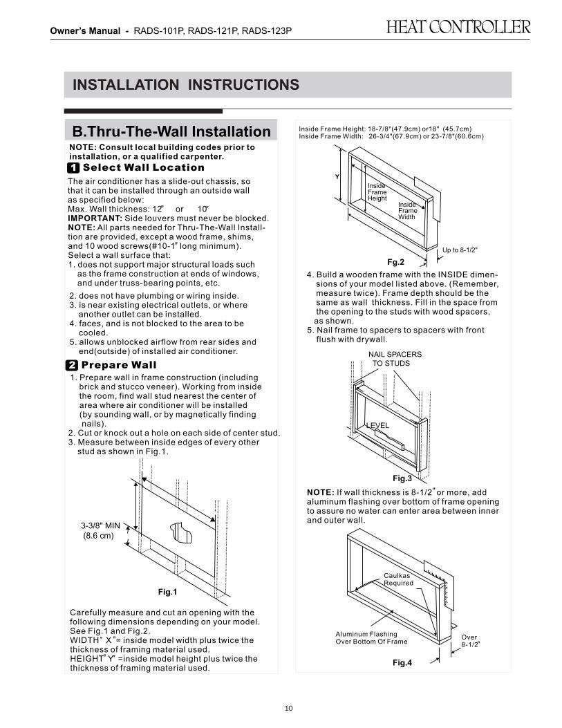
4. Build a wooden frame with the INSIDE dimen- sions of your model listed above. (Remember, measure twice). Frame depth should be the same as wall thickness. Fill in the space from the opening to the studs with wood spacers, as shown.5. Nail frame to spacers to spacers with front flush with drywall.
Inside Frame Height: 18-7/8"(47.9cm) or18" (45.7cm)Inside Frame Width: 26-3/4"(67.9cm) or 23-7/8"(60.6cm)
Fg.2
FrameHeight
InsideFrame
Y
Inside
Width
Up to 8-1/2"
B.Thru-The-Wall Installation
1 Select Wall Location
The air conditioner has a slide-out chassis, sothat it can be installed through an outside wallas specified below: Max. Wall thickness: 12 or 10IMPORTANT: Side louvers must never be blocked.NOTE: All parts needed for Thru-The-Wall Install-tion are provided, except a wood frame, shims, and 10 wood screws(#10-1 long minimum). Select a wall surface that:1. does not support major structural loads such as the frame construction at ends of windows, and under truss-bearing points, etc.
NOTE: Consult local building codes prior to installation, or a qualified carpenter.
2 Prepare Wall1. Prepare wall in frame construction (including brick and stucco veneer). Working from inside the room, find wall stud nearest the center of area where air conditioner will be installed (by sounding wall, or by magnetically finding nails).2. Cut or knock out a hole on each side of center stud.3. Measure between inside edges of every other stud as shown in Fig.1.
Fig.1
3-3/8" MIN (8.6 cm)
Carefully measure and cut an opening with thefollowing dimensions depending on your model.See Fig.1 and Fig.2. WIDTH X = inside model width plus twice thethickness of framing material used.HEIGHT Y =inside model height plus twice thethickness of framing material used.
2. does not have plumbing or wiring inside.3. is near existing electrical outlets, or where another outlet can be installed.4. faces, and is not blocked to the area to be cooled.5. allows unblocked airflow from rear sides and end(outside) of installed air conditioner.
Owner’s Manual - RADS-101P, RADS-121P, RADS-123P
11
11
INSTALLATION INSTRUCTIONS
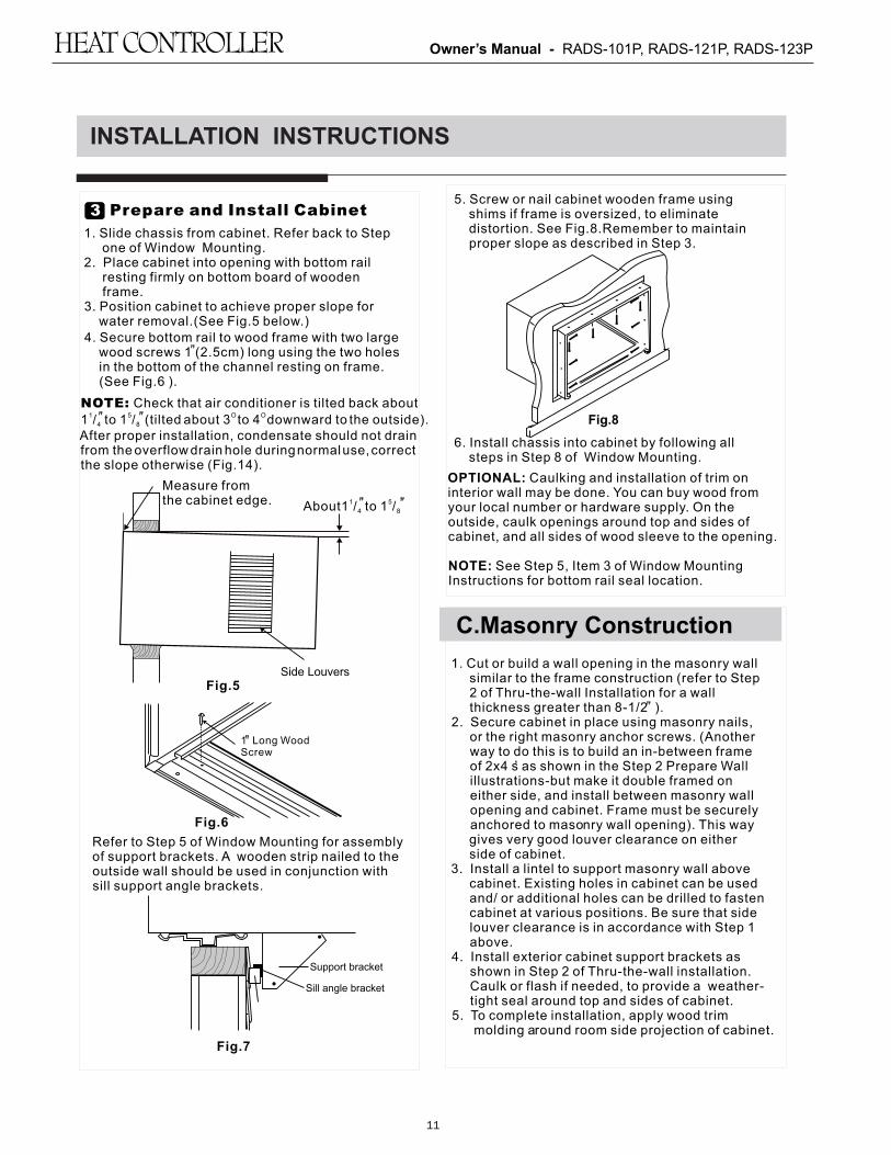
6. Install chassis into cabinet by following all steps in Step 8 of Window Mounting.
1. Cut or build a wall opening in the masonry wall similar to the frame construction (refer to Step 2 of Thru-the-wall Installation for a wall thickness greater than 8-1/2 ).2. Secure cabinet in place using masonry nails, or the right masonry anchor screws. (Another way to do this is to build an in-between frame of 2x4 s as shown in the Step 2 Prepare Wall illustrations-but make it double framed on either side, and install between masonry wall opening and cabinet. Frame must be securely anchored to masonry wall opening). This way gives very good louver clearance on either side of cabinet.3. Install a lintel to support masonry wall above cabinet. Existing holes in cabinet can be used and/ or additional holes can be drilled to fasten cabinet at various positions. Be sure that side louver clearance is in accordance with Step 1 above.4. Install exterior cabinet support brackets as shown in Step 2 of Thru-the-wall installation. Caulk or flash if needed, to provide a weather- tight seal around top and sides of cabinet.5. To complete installation, apply wood trim molding around room side projection of cabinet.
C.Masonry Construction
,
5. Screw or nail cabinet wooden frame using shims if frame is oversized, to eliminate distortion. See Fig.8.Remember to maintain proper slope as described in Step 3.
Fig.8
OPTIONAL: Caulking and installation of trim oninterior wall may be done. You can buy wood fromyour local number or hardware supply. On the outside, caulk openings around top and sides ofcabinet, and all sides of wood sleeve to the opening.
NOTE: See Step 5, Item 3 of Window Mounting Instructions for bottom rail seal location.
3 Prepare and Install Cabinet
1. Slide chassis from cabinet. Refer back to Step one of Window Mounting.2. Place cabinet into opening with bottom rail resting firmly on bottom board of wooden frame.3. Position cabinet to achieve proper slope for water removal.(See Fig.5 below.)4. Secure bottom rail to wood frame with two large wood screws 1 (2.5cm) long using the two holes in the bottom of the channel resting on frame. (See Fig.6 ).
Fig.5Side Louvers
1 Long WoodScrew
Fig.6
Refer to Step 5 of Window Mounting for assemblyof support brackets. A wooden strip nailed to theoutside wall should be used in conjunction withsill support angle brackets.
Support bracket
Sill angle bracket
Fig.7
NOTE: Check that air conditioner is tilted back about1 5 O O 1 / to 1 / (tilted about 3 t o 4 downward t o th e o utside).4 8
After proper installation, condensate should not drain from the overflow drain h ole d uringn ormalu se,c orrect the slope otherwise (Fig.14).
1 5About1 / to 1 /4 8
Measure fromthe cabinet edge.

Owner’s Manual - RADS-101P, RADS-121P, RADS-123P
12
NORMAL SOUNDS
All the illustrations in this manual are for explanation purpose only. Your air conditioner may be slightly different. The actual shape shall prevail.
NOTE:
AIR CONDITIONER FEATURES
Before you begin, thoroughly familiarize yourself with the control panel as shown below and all its functions, then follow the symbol for the functions you desire. The unit can be controlled by the unit control alone or with the remote.
ELECTRONIC CONTROL OPERATING INSTRUCTIONS
12
TO TURN UNIT ON OR OFF:
Press ON/OFF button to t urn u nit o n o r o ff. NOTE:Th e uni t w i l l i ni ti a te a utomatically the Energy
Saver function under C ool, Dry, Auto(only Au to-Cooling and Auto-Fan) modes.
TO CHANGE TEMPERATURE SETTING:
Press / UP/DOWN button to change temperature setting.
NOTE:Press or hold either UP( ) or DOWN ( ) buttonuntil the desired temperature is seen on the display. This temperature will be automatically maintained
O O O Oanywhere between 62 F(17 C) and 86 F(30 C). If you want the display to read the actual room temperature, see To Operate on Fan Only section.
CLEAN AIR FEATURE: (on some models)
Press Clean Air button, the ion generator is energized and will help to remove p ollen an d imp urities from the air, and trap them in the filter.(Electric Heating models)
Sound of Rushing Air
At the front of the unit, you mayhear the sound of rushing airbeing moved by the fan
High Pitched Chatter
High efficiency compressorsmay have a high pitched chatterduring the cooling cycle.
Gurgle/Hiss
Gurgling or hissing noise may be heard due to refrigerant passing through evaporator during normal operation.
Pinging or Switching
Droplets of water hitting condenserduring normal operation may cause pinging or switching sounds.
Vibration
Unit may vibrate and make noisebecause of poor wall or windowconstruction or incorrect installation.
SleepCheckFilter
FollowMe
Auto
On/off
FanHigh
Med
Low
EnergySaver
onoff
Timer
Auto
Fan
Cool
DryMode
TEMP/TIMER
TEMP/TIMER
Heat
(Cooling Only Models)
EnergySaver
Sleep CheckFilter
On
Timer
Off
High
Auto
On/OffLowFan SpeedMode
Dry
Auto
Cool
Fan
Temp/Timer
Temp/Timer
Follow Me
Med
CleanAir
EnergySaver
Sleep CheckFilter
On
Timer
Off
High
Auto
On/OffLowFan SpeedMode
Dry
Auto
Cool
Fan
Temp/Timer
Temp/Timer
Follow Me
Med
CleanAir
Remote signal receptor

Owner’s Manual - RADS-101P, RADS-121P, RADS-123P
13
13
AIR CONDITIONER FEATURES
TO ADJUST FAN SPEEDS:
Press to select the Fan Speed in four steps-Auto, Low, Med or High. Each time the button is pressed, the fan speed mode is shifted.For some models, thefan speed can not be adjusted under HEAT mode. On Dry mode,the fan speed is controlled at Low automatically.
TO SELECT THE OPERATING MODE:
To choose operating mode, press Mode button.Each time you press the button, a mode is selected in a sequence that goes from Auto, Cool, Dry ,heat(coolingonly models without)and Fan. The indicator light beside will be illuminated and remained on once the mode is selected.
To operate on Auto feature:
In this mode, the fan speed cannot be adjusted, it starts automatically at a speed according to the room temperature.
To operate on Fan Only:Use this function only when cooling is not desired,such as for room air circulation or to exhaust stale air(on some models). (Remember to open the vent during this function, but keep it closed during cooling for maximum cooling efficiency.) You can choose any fan speed you prefer.During this function, the display will show the actualroom temperature, not the set temperature as in thecooling mode.
To operate on Dry mode:In this mode, the air conditioner will generally operate in the form of a dehumidifier. Since the conditioned space is a closed or sealed area, some degree of cooling will continue.
When you set the air conditioner in AUTO mode, it will automatically select cooling, heating(cooling only models without), or fan only operation depending on what temperature you have selected and the room temperature.The air conditioner will control room temperature automatically round the temperature point set by you.
In Fan only mode ,the temperature is not adjusted.
The unit will initiate automatically the Energy Saver function under Cool, Dry, Auto(only Auto-Cooling and Auto-Fan) modes.
SLEEP FEATURE:
Press Sleep button to initiate the sleep mode. In this mode the selected temperature will increase
O O(cooling) or decrease (heating) by 2 F/1(or 2) C 30 minutes after the mode is s elected. T he t emperature will then increase (cooling) or decrease (heating) b y
O Oanother 2 F/1(or 2) C after an additional 30 minutes.T his n ew t emperature w ill be m aintained f or 6 h ours before i t r eturns to th e originally se lected tem perature.This ends the Sleep mode and the u nit w ill c ontinuet o o perate as originally programmed. The Sleep mode program can be cancelled at any time during operation by pressing the Sleep button again.
Press Check filter button to initiate theis feature. This feature is a reminder to clean the Air Filter for more efficient operation. The LED(light) will illumi- nate after 250 hours of operation. To reset after cleaning the filter, press the Check Filter button and the light will go off.
CHECK FILTER FEATURE:
ENERGY SAVER FEATURE:
Press Energy saver button to initiate this function.This function is available on COOL, DRY, AUTO (only AUTO-COOLING and AUTO-FAN) modes.The fan will continue to run for 3 minutes after the compressor shuts off.The fan then cycles on for 2 minutes at 10 minute intervals until the room temperature is above the set temperature, at which time the compressor turns back on and Cooling Starts.
FOLLOW ME FEATURE:(on some models)
This feature can be activated from the remote control ONLY. The remote control serves as a remote thermostat allowing for the precise temperature control at its location.To activate the Follow Me feature, point the remote control towards the unit and press the Follow Me button. The remote display is actual temperature at its location. The remote control will send this signal to the air conditioner every 3 minutes interval until press the Follow Me button again.If the unit does not receive the Follow Me signal during any 7 minutes interval, the unit will beep to indicate the Follow Me mode has ended.
When the unit is on or off, first press Timer button, the TIMER ON indicator light illuminates. It indicates the Auto Start program is initiated. When the time of TIMER ON is displayed ,press the Timer button again, the TIMER OFF indicator light illuminates. It indicates the Auto Stop program is initiated. Press or hold the UP or DOWN button to change the Auto time by 0.5 hour increments, up to 10 hours,then at 1 hour increments up to 24 hours.The control will count down the time remaining until start. The selected time will register in 5 seconds, and the system will automatically revert back to display the previous temperature setting or room temperature when the unit is on.(when the unit is off,there is no display.) Turning the unit ON or OFF at any time or adjusting the timer setting to 0.0 will cancel the Auto Start/Stop timed program.
TIMER: AUTO START/STOP FEATURE:
Light flashingFollow Me

Owner’s Manual - RADS-101P, RADS-121P, RADS-123P
14
AIR CONDITIONER FEATURES
O OShows the set temperature in " C" or " F" and theAuto-timer settings.While on Fan only mode,it shows the room temperature.
DISPLAYS:
-Evaporator temperature sensor error-Unplug the unit and plug it back in.If error repeats, call for service. NOTE: " "is displayed as shown in the left picture. HS -Electric heating sensor error-Unplug the unit and plug it back in.If error repeats, call for service.
Error codes:AS-Room temperature sensor error-Unplug the unit and plug it back in.If error repeats, call for service. NOTE:In Fan only mode,it will display"LO" or "HI".
If the unit breaks off unexpectedly due to the power cut, it will restart with the previous function setting automatically when the power resumes.
DISPLAYS:
NOTE:
Air Directional Louvers
ADDITIONAL THINGS YOU SHOULD KNOW
Now that you have mastered the operating procedure, here are more features in your control that you should become familiar with. The Cool circuit has an automatic 3 minute time delayed start if the unit is turned off and on quickly. This prevents overheating of the compressor and possible circuit breaker tripping.The fan will continue to run during this time. The control is capable of displaying temperature in degrees Fahrenheit or degrees Celsius. To convert from one to the other, press and hold the Left and Right Temp/Timer buttons at the same time, for 3 seconds.
Fresh Air Vent Control
Fig. A (VENT CLOSED) Fig. B (VENT OPEN)
Fig. C (VENT & EXHAUST OPEN)
The Fresh Air Vent allows the air conditioner to:1. Recirculate inside air - Vent Closed (See Fig.A)2. Draw fresh air into the room- Vent Open (see Fig.B)3. Exchange air from the room and draws fresh air into the room - Vent and Exhaust Open (see Fig.C)
CARE AND CLEANING
CAUTIONClean your air conditioner occasionally to keep it looking
new. Be sure to unplug the unit before cleaning to
prevent chock or fire hazards.
Air Filter Cleaning
The air filter should be checked at least once a month to see
if cleaning is necessary. Trapped particles in the filter can
build up and cause an accumulation of frost on the cooling
coils.
14
Displays
Air Directional Louvers
The 4-way air directional louvers allow you todirect the air flow Up or Down(on some models)and Left or Right throughout the room as needed. To adjust the air directional louvers side-to -side, use the center handles as you move it side-to-side.
Air Direction(4- way)

Owner’s Manual - RADS-101P, RADS-121P, RADS-123P
CARE AND CLEANING
Air Filter Cleaning
Winter Storage If you plan to store the air conditioner during the winter,
remove it carefully from the window according to the
installation instructions. Cover it with plastic or return it to
the original carton.
Cabinet Cleaning
Be sure to unplug the air conditioner to prevent shock or fire
hazard. The cabinet and front may be dusted with an oil-free
cloth or washed with a cloth dampened in a solution of warm
water and mild liquid dishwashing detergent. Rinse thoroughly
and wipe dry.
Never use harsh cleaners, wax or polish on the cabinet front.
Be sure to wring excess water from the cloth before wiping
around the controls. Excess water in or around the controls
may cause damage to the air conditioner.
Plug in air conditioner.
TROUBLESHOOTING TIPS
Before calling for service, review this list. It may save your time and expense. This list includes common
occurrences that are not the result of defective workman-ship or materials in this appliance.
Solution
Air conditionerdoes not start
Wall plug disconnected. Push plug firmly into wall outlet.
House fuse blown or circuit breaker tripped. Replace fuse with time delay type orreset circuit breaker.
Plug Current Device Tripped. Press the RESET button.
Problem
Air from unit doesnot feel coldenough
Set to a Lower temperature.
O ORoom temperature below 62 F(17 C ). Cooling may not occur until room temperature O Orises above 62 F(17 C).
Thermostat set too cold for night-time cooling. To defrost the coil, set to FAN ONLYmode. Then, set temperature to a Higher setting.
Temperature sensing behind air filter element touching cold coil. Keep it from the cold coil.
Air filter may be dirty. Clean filter. Refer to Care and Cleaning section. To defrost,set to FAN ONLY mode.
Power is OFF. Turn power ON.
Air conditioner cooling, but roomis too warm- ice forming on cooling coil behind decorative front.
O OOutdoor temperature below 64 F(18 C). To defrost the coil, set FAN ONLY mode.
Compressor stopped when changing modes. Wait for 3 minutes after set to the COOL mode.
15
Push the vent handle to the Vent Closed position
(where applicable). Open the front panel.
Take the filter by the center and pull up and out.Wash the filter u sing l iquid d ishwashing d etergent a nd w arm
water. Rinse filter thoroughly. Gently shake excess water
from the filter. Be sure the filter is thoroughly dry before
replacing. Or, instead of washing you may vacuum the filter
clean.
Note: Never use hot water over 40°C (104°F) to clean the air
filter. Never attempt to operate the unit without the air filter.
15

Owner’s Manual - RADS-101P, RADS-121P, RADS-123P
16
TROUBLESHOOTING TIPS
SolutionProblem
Dirty air filter- air restricted. Clean air filter. Refer to Care and Cleaning section.
Unit recently turned on in hot room. Allow additional time to remove Stored heat from walls, ceiling, floor and furniture.
Air conditioner cooling, but roomis too warm- NO ice forming on cooling coil behind decorative front.
Temperature is set too High, set temperature to a Lower setting.
Air directional louvers positioned improperly. Position louvers for better air distribution.
Front of units is blocked by drapes, blinds, furniture, etc. - restricts air distribution. Clear blockage in front of unit.
Doors, windows, registers, etc. Open- cold air escapes. Close doors, windows, registers.
Air conditioner turns onand off rapidly
Noise when unit is cooling
Water drippingINSIDE when unit is cooling.
Improper installation. Tilt air conditioner slightly to the outside to allow water drainage. Refer to installation instructions - check with installer.
Dirty air filter- air restricted. Clean air filter.
Air movement sound. This is normal . If too loud, set to a slower FAN setting.
Outside temperature extremely hot. Set FAN speed to a Higher setting to bring air past cooling coils more frequently.
Window vibration - poor installation. Refer to installation instructions or check with installer.
Water drippingOUTSIDE when unit is cooling.
Remote Sensing Deactivating Prematurely(some models)
Remote control not located within range. Place remote control within 20 feet & 180 , radius of the front of the unit.
Remote control signal obstructed. Remove obstruction.
Room too cold Set temperature too low. Increase set temperature.
Unit removing large quantity of moisture from humid room. This is normal during excessively humid days.
16
Owner’s Manual - RADS-101P, RADS-121P, RADS-123P
17
Congratuations on purchasing your new HVAC equipment. It’s been designed for long life and reliable service, and is backed by one of the strongest warranties in the industry. Your unit automatically qualifies for the warranty coverage listed below, providing you keep your proof of purchase (receipt) for the equipment and meet the warranty conditions.
LIMITED ONE (1) YEAR PARTS AND LABOR EXPRESS WARRANTYComfort-Aire® warrants all parts of the Room Air Conditioner with electronic controls to be free from defects in workmanship and materials for normal use and maintenance for one (1) year from the date of purchase by the original consumer. This Express Limited Warranty applies only when the Room Air Conditioner is installed and operated per Comfort-Aire® installation and operating instructions for normal use. Ready access to the unit for service is the responsibility of the owner.
LIMITED FIVE (5) YEAR SEALED SYSTEM WARRANTYThe sealed system only is warranted to be free from defects in workmanship and materials for normal use and maintenance for a four additional years, for a total of five (5) years from the date of purchase by the original consumer. The sealed system consists of compressor, evaporator, condenser, and interconnecting tubing. This five year warranty applies only when the system is installed and operated per Comfort-Aire® installation and operation instructions for normal use.
EXCEPTIONSThe Limited Express Warranty does not cover normal maintenance Comfort-Aire® recommends that regular inspection/maintenance be performed at least once a season and proof of maintenance be kept. Additionally, labor charges (except as described in the Limited One Year Warranty paragraph), diagnostic charges, transportation charges for replacement parts, replacement of refrigerant or filters, and any other service calls/repairs are not covered by this Limited Warranty. It also does not cover any portion or component of the system that is not supplied by Comfort-Aire®, regardless of the cause of failure of such portion or component.
CONDITIONS FOR WARRANTY COVERAGE• Unit must be operated according to Comfort-Aire® operating
instructions included with the unit and cannot have been subjected to accident, alteration, improper repair, neglect or misuse, or an act of God (such as a flood)
• Serial numbers and/or rating plate have not been altered or removed
• Performance cannot be impaired by use of any product not authorized by Comfort-Aire®, or by any adjustments or adaptations to components
• Damage has not been a result of inadequate wiring or voltage conditions, use during brown-out conditions, or circuit interruptions
• Air flow around any section of the unit has not been restricted• Unit remains in the original installation• Unit was not purchased over the internet
DURATION OF WARRANTY & REGISTRATIONThe warranty begins on the date of purchase by the orginal consumer. The consumer must retain a receipted bill of sale as proof of warranty period. Without this proof, the express warranty begins on the date of shipment from the factory.
REMEDY PROVIDED BY THE LIMITED EXPRESS WARRANTYThe sole remedy under the Limited Warranty is replacement of the defective part. If replacement parts are required within the period of this warranty, Comfort-Aire® replacement parts shall be used; any warranty on the replacement part(s) shall not affect the applicable original unit warranty. Ready access to the unit for service is the owner’s responsibility. Labor to diagnose and replace the defective part is not covered by this Limited Express Warranty. If for any reason the replacement part/product is no longer available during the warranty period, Comfort-Aire® shall have the right to allow a credit in the amount of the current suggested retail price of the part/product instead of providing repair or replacement.
LIMITATION OF LIABILITY1. There are no other express or implied warranties. Comfort-
Aire® makes no warranty of merchantability. We do not warrant that the unit is suitable for any particular purpose or can be used in buildings or rooms of any particular size or condition except as specifically provided in this document. There are no other warranties, express or implied, which extend beyond the description in this document.
2. All warranties implied by law are limited in duration to the one-term of the parts warranty. Your exclusive remedy is limited to the replacement of defective parts. We will not be liable for any consequential or incidental damages caused by any defect in this unit.
3. This warranty gives you specific legal rights and you may also have other rights which vary from state to state. Some states do not allow limitation on how long an implied warranty lasts or do not allow the exclusion or limitation of incidental or consequential damages, so the above limitations or exclusions may not apply to you.
4. No warranties are made for units sold outside the continental United States and Canada. Your distributor or final seller may provide a warranty on units sold outside these areas.
5. Comfort-Aire® will not be liable for damages if our performance regarding warranty resolution is delayed by events beyond our control including accident, alteration, abuse, war, government restrictions, strikes, fire, flood, or other acts of God.
HOW TO OBTAIN WARRANTY SERVICE OR PARTSIf you have a warranty claim, contact Service Power, our network of service providers, at 866-557-1865. If they are unable to take care of your claim, write to Comfort-Aire®, PO Box 1089, Jackson MI 49204. Enclose a description of the problem and a report of inspection by your installer or service person. Include the model number, serial number and date of purchase.
Owner responsibilities are set forth in the instruction manual—read it carefully.
KEEP THIS INFORMATION AS A RECORD OF YOUR PURCHASE PRODUCT IDENTIFICATION INSTALLATION
Model Number Installer Name (if used)
Serial Number Phone Number/Contact Information
Date of Purchase Date Installation Completed
o Component of new HVAC system o Replacement only
Remember to retain your bill of sale as proof of warranty period.
LIMITED EXPRESS WARRANTY
RADS_WARRANTY_12/2015

Owner’s Manual - RADS-101P, RADS-121P, RADS-123P
18

12/2015
www.marsdelivers.com • www.heatcontroller.com