rooftrac® installation manual-final - solarflexion · installation manual page 1 of 16 ......
TRANSCRIPT

RoofTrac®
Installation Manual
Page 1 of 16COPYRIGHT PROFESSIONAL SOLAR PRODUCTS 2015: All information contained in this manual is property of Professional Solar Products (PSP). TileTrac® is a registered trademark for PSP and is covered under U.S. patent #5,746,029. RoofTrac® and FastJack® are registered trademarks for PSP and are covered under U.S. patent #6,360,491. RoofTrac® bonding designs patent pending. (v 1.1)
APPLICATION:The RoofTrac® mounting system consists of support rails and top-down clamping hardware which is integrated with either a TileTrac® or FastJack® attachment device. The RoofTrac® mounting system can be utilized on virtually all standard construction residential roof tops, to install UL1703 approved framed solar modules.
WARNING:All Professional Solar Products (ProSolar®) are engineered and tested to withstand stated specifi cations (as stated on published specifi cation sheets) when installed properly. Failure to install properly may decrease the performance of installation.
SAFETY:All regional safety requirements should be followed when installing Professional Solar Products. All tools and equipment located on the roof should be secured to avoid falling object hazards. All equipment/tools should be properly maintained and inspected prior to use. Any exposed studs should be protectively capped to avoid injury. This racking system may be used to ground and/or mount a PV module complying with UL 1703 only when the specifi c module frame has been evaluated for grounding and/or mounting compliance with the included instructions. This installation manual is intended for use by professional installers with a working knowledge of construction principles.
• Cordless impact wrench• Cordless drill• 1/2” Irwin #10 Unibit • 1/2” deep socket
• Torque wrench• RoofTrac® rail spreader (optional)• Reciprocating saw• Flashing
• 3/8” Nut driver• 3/16” Carbide drill• 5/52” Hex L key
This �le contains following:-house-roof line-tile (standard)-FastJack �ashing mounts-with slice installed-with end and mid clamps intalled to rail-rail face up-rail face down
Explanation or Install Tip
Critical for Safety
Important ProductPerformance Information
Symbol Legend
UL2703Class A
Fire Rated
Tool List

RoofTrac®
Installation Manual
Page 2 of 16COPYRIGHT PROFESSIONAL SOLAR PRODUCTS 2015: All information contained in this manual is property of Professional Solar Products (PSP). TileTrac® is a registered trademark for PSP and is covered under U.S. patent #5,746,029. RoofTrac® and FastJack® are registered trademarks for PSP and are covered under U.S. patent #6,360,491. RoofTrac® bonding designs patent pending. (v 1.1)
Parts List
3”Rail, 2-1/2” Rail, and 1-1/2” Rail
FastJack® : 3”, 4.5”, 6”, and 7.5”
Self-Bonding Mid Clamp Assembly
End Clamp Assembly
Module Bonding
Mid-Clamp Channel Nut
End Clamp Bonding Channel Nut
TileTrac® 4”& 6” Stud
Universal Self-Bond-ing Splice Assembly
FastJack® E-Series: 2”, 3”, 4.5”, 6”,and
7.5”
Ilsco® SGB-4 Grounding Lug
FastJack® E-Series Flashing
Decorative Front Skirt & Clamp Set
Flashing stamped with “TileTrac® USA”
Microinverter/ Optimizer Bonding
Channel Nut Assembly
Clamps 180 in-lb (15 ft-lb)Rail to FastJack® 180 in-lb (15 ft-lb)FastJack® Lag Screw: Fully SeatTileTrac® Lag Screw: Fully seatTileTrac® Nut: 180 in-lb (15 ft-lb)
Skirt Clip to Module: 48 in-lb (4 ft-lb)Clip to Skirt: 84 in-lb (7 ft-lb)Splice: 180 in-lb (15 ft-lb)Ilsco Grounding Lug: 35 in-lb
Torque Values
RoofTrac®
Installation Manual
Page 3 of 16COPYRIGHT PROFESSIONAL SOLAR PRODUCTS 2015: All information contained in this manual is property of Professional Solar Products (PSP). TileTrac® is a registered trademark for PSP and is covered under U.S. patent #5,746,029. RoofTrac® and FastJack® are registered trademarks for PSP and are covered under U.S. patent #6,360,491. RoofTrac® bonding designs patent pending. (v 1.1)
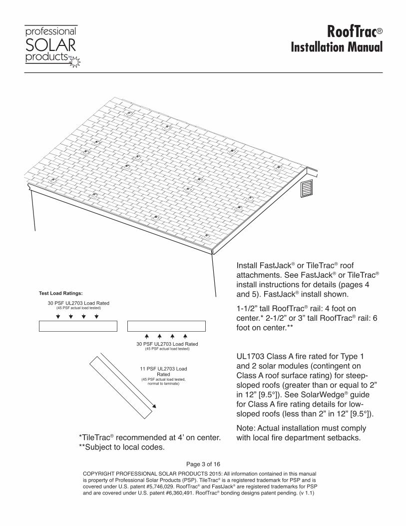
Install FastJack® or TileTrac® roof attachments. See FastJack® or TileTrac® install instructions for details (pages 4 and 5). FastJack® install shown.
1-1/2” tall RoofTrac® rail: 4 foot on center.* 2-1/2” or 3” tall RoofTrac® rail: 6 foot on center.**
UL1703 Class A fire rated for Type 1 and 2 solar modules (contingent on Class A roof surface rating) for steep-sloped roofs (greater than or equal to 2” in 12” [9.5°]). See SolarWedge® guide for Class A fire rating details for low-sloped roofs (less than 2” in 12” [9.5°]).
Note: Actual installation must comply with local fire department setbacks.
Test Load Ratings:
11 PSF UL2703 Load Rated
(45 PSF actual load tested, normal to laminate)
30 PSF UL2703 Load Rated (45 PSF actual load tested)
30 PSF UL2703 Load Rated (45 PSF actual load tested)
*TileTrac® recommended at 4’ on center.**Subject to local codes.
RoofTrac®
Installation Manual
Page 4 of 16COPYRIGHT PROFESSIONAL SOLAR PRODUCTS 2015: All information contained in this manual is property of Professional Solar Products (PSP). TileTrac® is a registered trademark for PSP and is covered under U.S. patent #5,746,029. RoofTrac® and FastJack® are registered trademarks for PSP and are covered under U.S. patent #6,360,491. RoofTrac® bonding designs patent pending. (v 1.1)
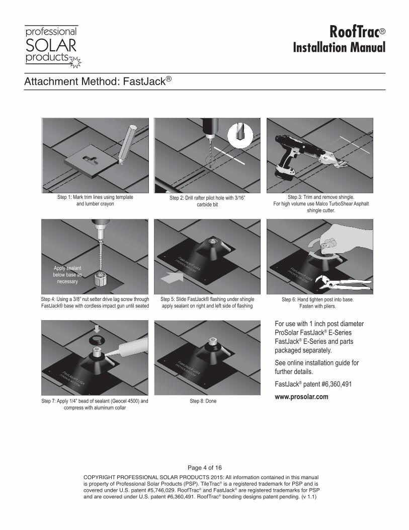
For use with 1 inch post diameter ProSolar FastJack® E-Series FastJack® E-Series and parts packaged separately. See online installation guide for further details. FastJack® patent #6,360,491 www.prosolar.com
Step 2: Drill rafter pilot hole with 3/16” carbide bit
Step 1: Mark trim lines using template and lumber crayon
Step 3: Trim and remove shingle.For high volume use Malco TurboShear Asphalt
shingle cutter.
Step 4: Using a 3/8” nut setter drive lag screw through FastJack® base with cordless impact gun until seated
Step 5: Slide FastJack® flashing under shingle apply sealant on right and left side of flashing
Step 6: Hand tighten post into base. Fasten with pliers.
Step 7: Apply 1/4” bead of sealant (Geocel 4500) and compress with aluminum collar
Step 8: Done
Apply sealantbelow base as
necessary
Attachment Method: FastJack®
RoofTrac®
Installation Manual
Page 5 of 16COPYRIGHT PROFESSIONAL SOLAR PRODUCTS 2015: All information contained in this manual is property of Professional Solar Products (PSP). TileTrac® is a registered trademark for PSP and is covered under U.S. patent #5,746,029. RoofTrac® and FastJack® are registered trademarks for PSP and are covered under U.S. patent #6,360,491. RoofTrac® bonding designs patent pending. (v 1.1)
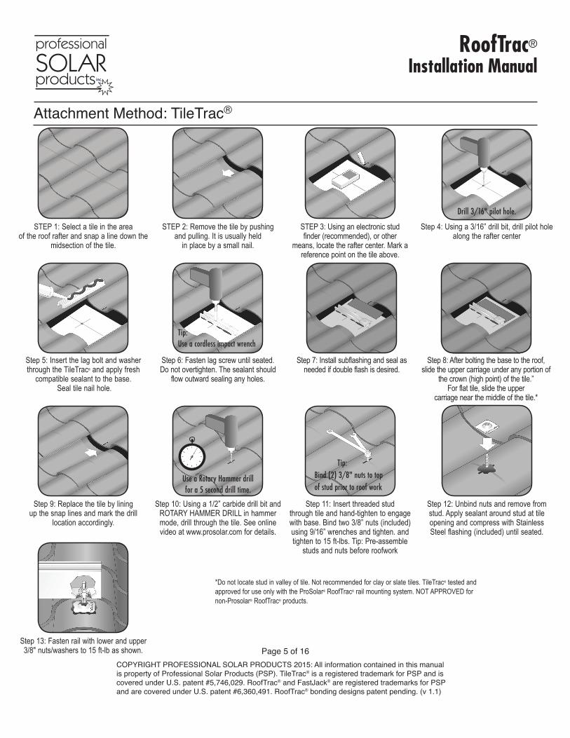
STEP 1: Select a tile in the area of the roof rafter and snap a line down the
midsection of the tile.
STEP 2: Remove the tile by pushing and pulling. It is usually held
in place by a small nail.
STEP 3: Using an electronic stud finder (recommended), or other
means, locate the rafter center. Mark a reference point on the tile above.
Step 5: Insert the lag bolt and washer through the TileTrac® and apply fresh
compatible sealant to the base. Seal tile nail hole.
Step 8: After bolting the base to the roof, slide the upper carriage under any portion of
the crown (high point) of the tile.” For flat tile, slide the upper
carriage near the middle of the tile.*
Step 7: Install subflashing and seal as needed if double flash is desired.
Step 9: Replace the tile by lining up the snap lines and mark the drill
location accordingly.
Step 12: Unbind nuts and remove from stud. Apply sealant around stud at tile opening and compress with Stainless Steel flashing (included) until seated.
*Do not locate stud in valley of tile. Not recommended for clay or slate tiles. TileTrac® tested and approved for use only with the ProSolar® RoofTrac® rail mounting system. NOT APPROVED for non-Prosolar® RoofTrac® products.
Step 13: Fasten rail with lower and upper 3/8" nuts/washers to 15 ft-lb as shown.
Step 6: Fasten lag screw until seated. Do not overtighten. The sealant should
flow outward sealing any holes.
Tip: Use a cordless impact wrench
Step 11: Insert threaded stud through tile and hand-tighten to engage with base. Bind two 3/8” nuts (included) using 9/16” wrenches and tighten. and tighten to 15 ft-lbs. Tip: Pre-assemble
studs and nuts before roofwork
Tip: Bind (2) 3/8" nuts to top of stud prior to roof work
Step 4: Using a 3/16” drill bit, drill pilot hole along the rafter center
Drill 3/16" pilot hole.
Step 10: Using a 1/2” carbide drill bit and ROTARY HAMMER DRILL in hammer mode, drill through the tile. See online video at www.prosolar.com for details.
Use a Rotary Hammer drill for a 5 second drill time.
Attachment Method: TileTrac®
RoofTrac®
Installation Manual
Page 6 of 16COPYRIGHT PROFESSIONAL SOLAR PRODUCTS 2015: All information contained in this manual is property of Professional Solar Products (PSP). TileTrac® is a registered trademark for PSP and is covered under U.S. patent #5,746,029. RoofTrac® and FastJack® are registered trademarks for PSP and are covered under U.S. patent #6,360,491. RoofTrac® bonding designs patent pending. (v 1.1)
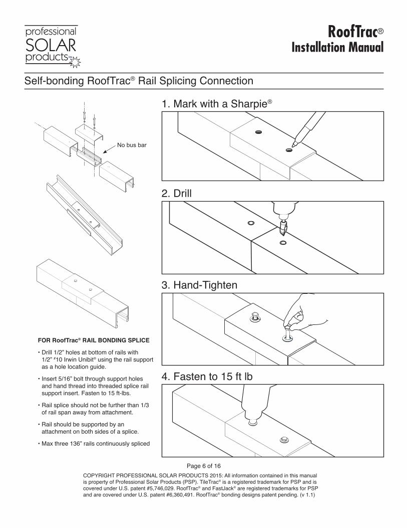
Self-bonding RoofTrac® Rail Splicing Connection
FOR RoofTrac® RAIL BONDING SPLICE
• Drill 1/2” holes at bottom of rails with 1/2” #10 Irwin Unibit® using the rail support as a hole location guide.
• Insert 5/16” bolt through support holes and hand thread into threaded splice rail support insert. Fasten to 15 ft-lbs.
• Rail splice should not be further than 1/3 of rail span away from attachment.
• Rail should be supported by an attachment on both sides of a splice.
• Max three 136” rails continuously spliced
1. Mark with a Sharpie®
2. Drill
3. Hand-Tighten
4. Fasten to 15 ft lb
No bus bar
RoofTrac®
Installation Manual
Page 7 of 16COPYRIGHT PROFESSIONAL SOLAR PRODUCTS 2015: All information contained in this manual is property of Professional Solar Products (PSP). TileTrac® is a registered trademark for PSP and is covered under U.S. patent #5,746,029. RoofTrac® and FastJack® are registered trademarks for PSP and are covered under U.S. patent #6,360,491. RoofTrac® bonding designs patent pending. (v 1.1)
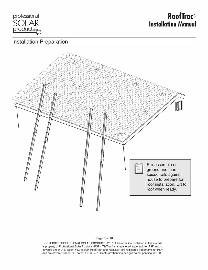
Pre-assemble on ground and lean spiced rails against house to prepare for roof installation. Lift to roof when ready.
Installation Preparation
RoofTrac®
Installation Manual
Page 8 of 16COPYRIGHT PROFESSIONAL SOLAR PRODUCTS 2015: All information contained in this manual is property of Professional Solar Products (PSP). TileTrac® is a registered trademark for PSP and is covered under U.S. patent #5,746,029. RoofTrac® and FastJack® are registered trademarks for PSP and are covered under U.S. patent #6,360,491. RoofTrac® bonding designs patent pending. (v 1.1)
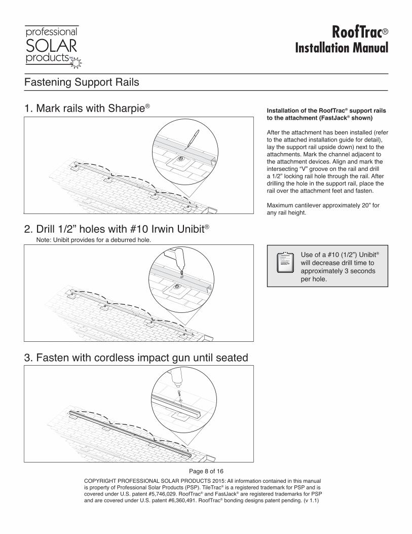
Use of a #10 (1/2”) Unibit® will decrease drill time to approximately 3 seconds per hole.
Installation of the RoofTrac® support rails to the attachment (FastJack® shown)
After the attachment has been installed (refer to the attached installation guide for detail), lay the support rail upside down) next to the attachments. Mark the channel adjacent to the attachment devices. Align and mark the intersecting “V” groove on the rail and drill a 1/2” locking rail hole through the rail. After drilling the hole in the support rail, place the rail over the attachment feet and fasten.
Maximum cantilever approximately 20” for any rail height.
1. Mark rails with Sharpie®
2. Drill 1/2” holes with #10 Irwin Unibit®
Note: Unibit provides for a deburred hole.
3. Fasten with cordless impact gun until seated
Fastening Support Rails
RoofTrac®
Installation Manual
Page 9 of 16COPYRIGHT PROFESSIONAL SOLAR PRODUCTS 2015: All information contained in this manual is property of Professional Solar Products (PSP). TileTrac® is a registered trademark for PSP and is covered under U.S. patent #5,746,029. RoofTrac® and FastJack® are registered trademarks for PSP and are covered under U.S. patent #6,360,491. RoofTrac® bonding designs patent pending. (v 1.1)
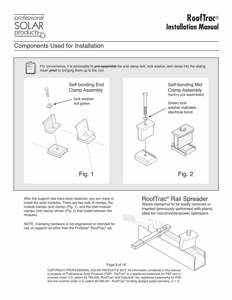
For convenience, it is adviseable to pre-assemble the end clamp bolt, lock washer, and clamp into the sliding insert prior to bringing them up to the roof.
After the support rails have been fastened, you are ready to install the solar modules. There are two sets of clamps: the outside clamps (end clamp) (Fig. 1), and the inter-module clamps (mid clamp) shown (Fig. 2) that install between the modules.
NOTE: Clamping hardware is not engineered or intended for use on support rail other than the ProSolar® RoofTrac® rail.
Fig. 1
Self-bonding End Clamp Assembly
Self-bonding Mid Clamp Assembly(factory pre-assembled)
Fig. 2
RoofTrac® Rail SpreaderAllows clamp/nut to be easily removed or inserted (previously performed with pliers). Ideal for microinverter/power optimizers.
Components Used for Installation
Green lock washer indicates electrical bond
lock washernot green
RoofTrac®
Installation Manual
Page 10 of 16COPYRIGHT PROFESSIONAL SOLAR PRODUCTS 2015: All information contained in this manual is property of Professional Solar Products (PSP). TileTrac® is a registered trademark for PSP and is covered under U.S. patent #5,746,029. RoofTrac® and FastJack® are registered trademarks for PSP and are covered under U.S. patent #6,360,491. RoofTrac® bonding designs patent pending. (v 1.1)
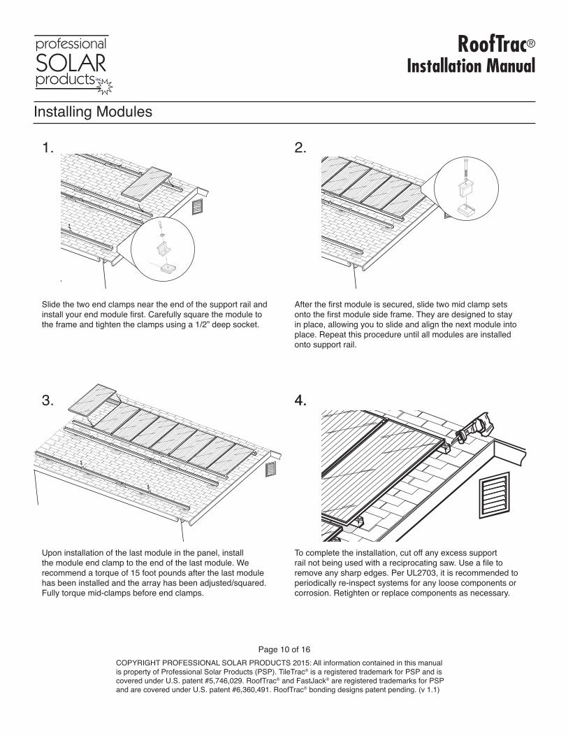
Slide the two end clamps near the end of the support rail and install your end module first. Carefully square the module to the frame and tighten the clamps using a 1/2” deep socket.
Upon installation of the last module in the panel, install the module end clamp to the end of the last module. We recommend a torque of 15 foot pounds after the last module has been installed and the array has been adjusted/squared. Fully torque mid-clamps before end clamps.
After the first module is secured, slide two mid clamp sets onto the first module side frame. They are designed to stay in place, allowing you to slide and align the next module into place. Repeat this procedure until all modules are installed onto support rail.
To complete the installation, cut off any excess support rail not being used with a reciprocating saw. Use a file to remove any sharp edges. Per UL2703, it is recommended to periodically re-inspect systems for any loose components or corrosion. Retighten or replace components as necessary.
This �le contains following:-house-roof line-tile (standard)-FastJack �ashing mounts-with slice installed-with end and mid clamps intalled to rail-LAST PANEL INSTALL
Installing Modules
1. 2.
3. 4.
This �le contains following:-house-roof line-tile (standard)-FastJack �ashing mounts-with slice installed-with end and mid clamps intalled to rail-LAST PANEL INSTALL
3. 4.
RoofTrac®
Installation Manual
Page 11 of 16COPYRIGHT PROFESSIONAL SOLAR PRODUCTS 2015: All information contained in this manual is property of Professional Solar Products (PSP). TileTrac® is a registered trademark for PSP and is covered under U.S. patent #5,746,029. RoofTrac® and FastJack® are registered trademarks for PSP and are covered under U.S. patent #6,360,491. RoofTrac® bonding designs patent pending. (v 1.1)
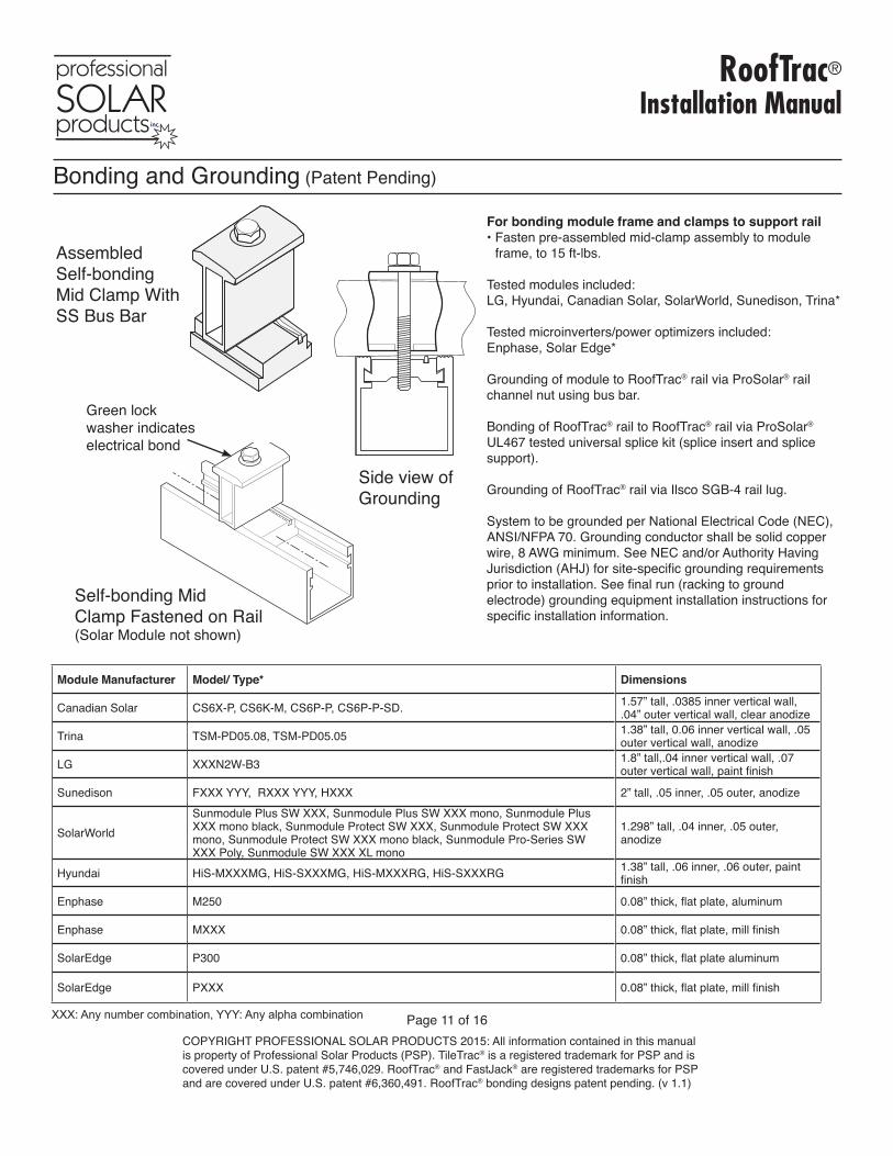
Bonding and Grounding (Patent Pending)
For bonding module frame and clamps to support rail• Fasten pre-assembled mid-clamp assembly to module
frame, to 15 ft-lbs.
Tested modules included: LG, Hyundai, Canadian Solar, SolarWorld, Sunedison, Trina*
Tested microinverters/power optimizers included: Enphase, Solar Edge*
Grounding of module to RoofTrac® rail via ProSolar® rail channel nut using bus bar.
Bonding of RoofTrac® rail to RoofTrac® rail via ProSolar® UL467 tested universal splice kit (splice insert and splice support).
Grounding of RoofTrac® rail via Ilsco SGB-4 rail lug.
System to be grounded per National Electrical Code (NEC), ANSI/NFPA 70. Grounding conductor shall be solid copper wire, 8 AWG minimum. See NEC and/or Authority Having Jurisdiction (AHJ) for site-specific grounding requirements prior to installation. See final run (racking to ground electrode) grounding equipment installation instructions for specific installation information.
Assembled Self-bondingMid Clamp With SS Bus Bar
Self-bonding Mid Clamp Fastened on Rail(Solar Module not shown)
Green lock washer indicates electrical bond
Side view of Grounding
Module Manufacturer Model/ Type* Dimensions
Canadian Solar CS6X-P, CS6K-M, CS6P-P, CS6P-P-SD. 1.57” tall, .0385 inner vertical wall, .04” outer vertical wall, clear anodize
Trina TSM-PD05.08, TSM-PD05.05 1.38” tall, 0.06 inner vertical wall, .05 outer vertical wall, anodize
LG XXXN2W-B3 1.8” tall,.04 inner vertical wall, .07 outer vertical wall, paint finish
Sunedison FXXX YYY, RXXX YYY, HXXX 2” tall, .05 inner, .05 outer, anodize
SolarWorldSunmodule Plus SW XXX, Sunmodule Plus SW XXX mono, Sunmodule Plus XXX mono black, Sunmodule Protect SW XXX, Sunmodule Protect SW XXX mono, Sunmodule Protect SW XXX mono black, Sunmodule Pro-Series SW XXX Poly, Sunmodule SW XXX XL mono
1.298” tall, .04 inner, .05 outer, anodize
Hyundai HiS-MXXXMG, HiS-SXXXMG, HiS-MXXXRG, HiS-SXXXRG 1.38” tall, .06 inner, .06 outer, paint finish
Enphase M250 0.08” thick, flat plate, aluminum
Enphase MXXX 0.08” thick, flat plate, mill finish
SolarEdge P300 0.08” thick, flat plate aluminum
SolarEdge PXXX 0.08” thick, flat plate, mill finish
XXX: Any number combination, YYY: Any alpha combination
RoofTrac®
Installation Manual
Page 12 of 16COPYRIGHT PROFESSIONAL SOLAR PRODUCTS 2015: All information contained in this manual is property of Professional Solar Products (PSP). TileTrac® is a registered trademark for PSP and is covered under U.S. patent #5,746,029. RoofTrac® and FastJack® are registered trademarks for PSP and are covered under U.S. patent #6,360,491. RoofTrac® bonding designs patent pending. (v 1.1)
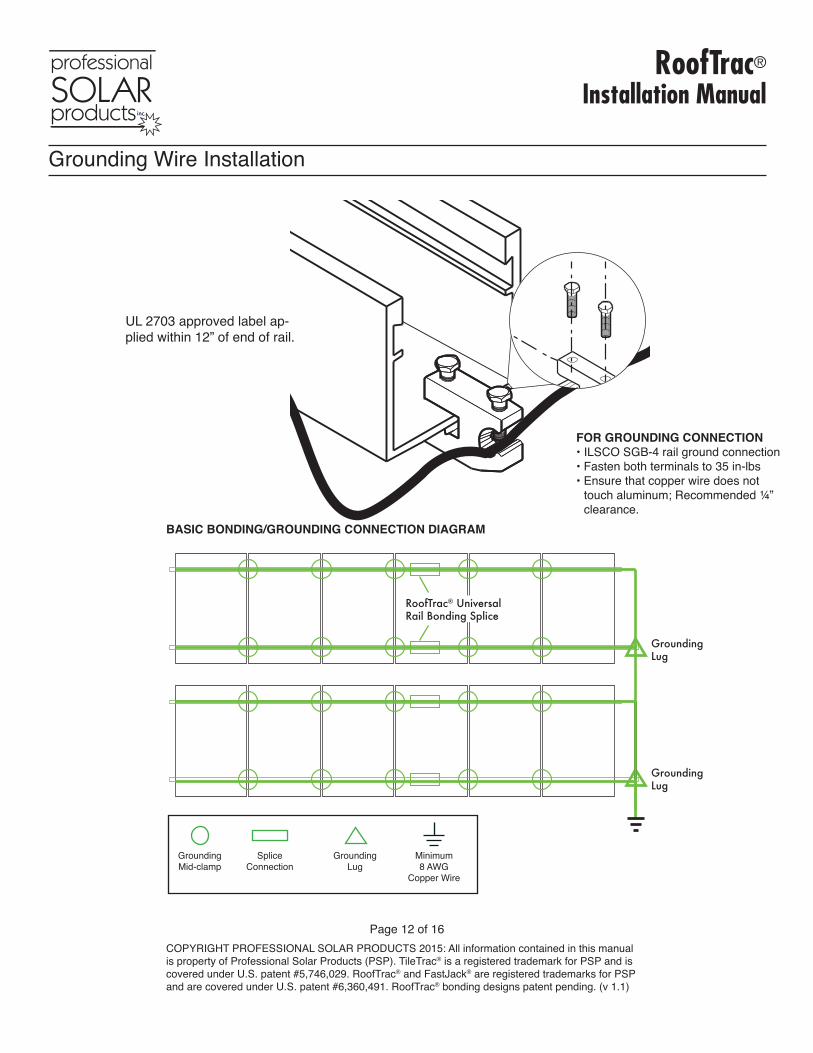
Grounding Wire Installation
FOR GROUNDING CONNECTION• ILSCO SGB-4 rail ground connection• Fasten both terminals to 35 in-lbs• Ensure that copper wire does not
touch aluminum; Recommended ¼” clearance.
BASIC BONDING/GROUNDING CONNECTION DIAGRAM
GroundingLug
GroundingLug
RoofTrac® UniversalRail Bonding Splice
GroundingMid-clamp
SpliceConnection
GroundingLug
Minimum8 AWG
Copper Wire
UL 2703 approved label ap-plied within 12” of end of rail.
RoofTrac®
Installation Manual
Page 13 of 16COPYRIGHT PROFESSIONAL SOLAR PRODUCTS 2015: All information contained in this manual is property of Professional Solar Products (PSP). TileTrac® is a registered trademark for PSP and is covered under U.S. patent #5,746,029. RoofTrac® and FastJack® are registered trademarks for PSP and are covered under U.S. patent #6,360,491. RoofTrac® bonding designs patent pending. (v 1.1)
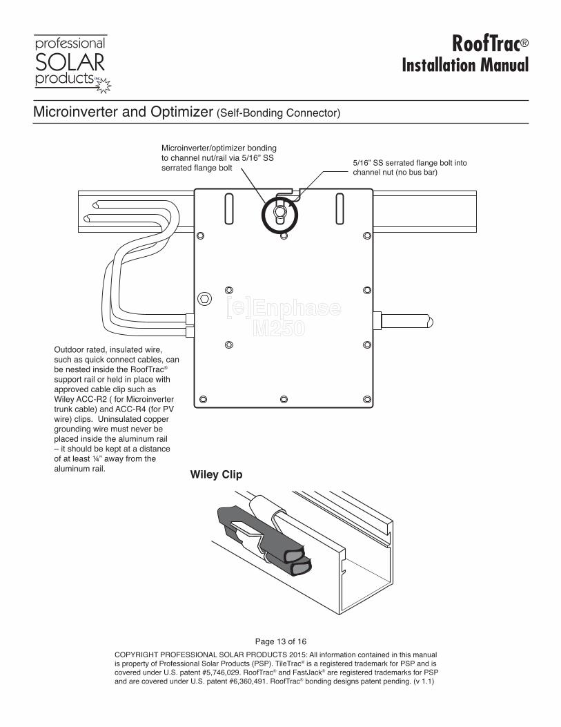
5/16” SS serrated flange bolt intochannel nut (no bus bar)
Microinverter and Optimizer (Self-Bonding Connector)
Outdoor rated, insulated wire, such as quick connect cables, can be nested inside the RoofTrac® support rail or held in place with approved cable clip such as Wiley ACC-R2 ( for Microinverter trunk cable) and ACC-R4 (for PV wire) clips. Uninsulated copper grounding wire must never be placed inside the aluminum rail – it should be kept at a distance of at least ¼” away from the aluminum rail.
Microinverter/optimizer bonding to channel nut/rail via 5/16” SS serrated flange bolt
Wiley Clip

RoofTrac®
Installation Manual
Page 14 of 16COPYRIGHT PROFESSIONAL SOLAR PRODUCTS 2015: All information contained in this manual is property of Professional Solar Products (PSP). TileTrac® is a registered trademark for PSP and is covered under U.S. patent #5,746,029. RoofTrac® and FastJack® are registered trademarks for PSP and are covered under U.S. patent #6,360,491. RoofTrac® bonding designs patent pending. (v 1.1)
Skirt NOT required for class A sloped roof fire rating. Type 1 and 2 modules.
Required: 5/32” hex L key, compund sliding miter saw with aluminum cutting blade or rafter angle square and portable circular saw with aluminum cutting blade.
Attach skirt bracket, approximately 5” from end of module, by placing around module frame and fastening bottom set screw with a 5/32” hex L key. Tighten to 4 ft-lb (approximately 1/4 turn after bottom out). Bracket not rated for snow load.
1. Slide skirt into slot opening and fasten top set screw with 5/32” hex L key. Tighten to 7 ft-lb (approximately 1/3 turn after bottoming out).
2. Use at least (2) brackets per module and at least (2) brackets per skirt. (See system overview on next page). Use cutoff saw with material holding clamp to trim skirt. Use a file to remove any sharp edges.
Front Skirt Bracket
Front Skirt
5/16 SS cup head screwUse 5/32” hex L key
5/16 SS cup head screwUse 5/32” hex L key
7 ft-lb torqueapprox. 1/3 turnafter bottom out
4 ft-lb torqueapprox. 1/4 turnafter bottom out
BONDING PATH
Front
5”
40”
65”
5”
Skirt Bracket location2 brackets per module2 brackets per skirt
Skirt Installation
RoofTrac®
Installation Manual
Page 15 of 16COPYRIGHT PROFESSIONAL SOLAR PRODUCTS 2015: All information contained in this manual is property of Professional Solar Products (PSP). TileTrac® is a registered trademark for PSP and is covered under U.S. patent #5,746,029. RoofTrac® and FastJack® are registered trademarks for PSP and are covered under U.S. patent #6,360,491. RoofTrac® bonding designs patent pending. (v 1.1)
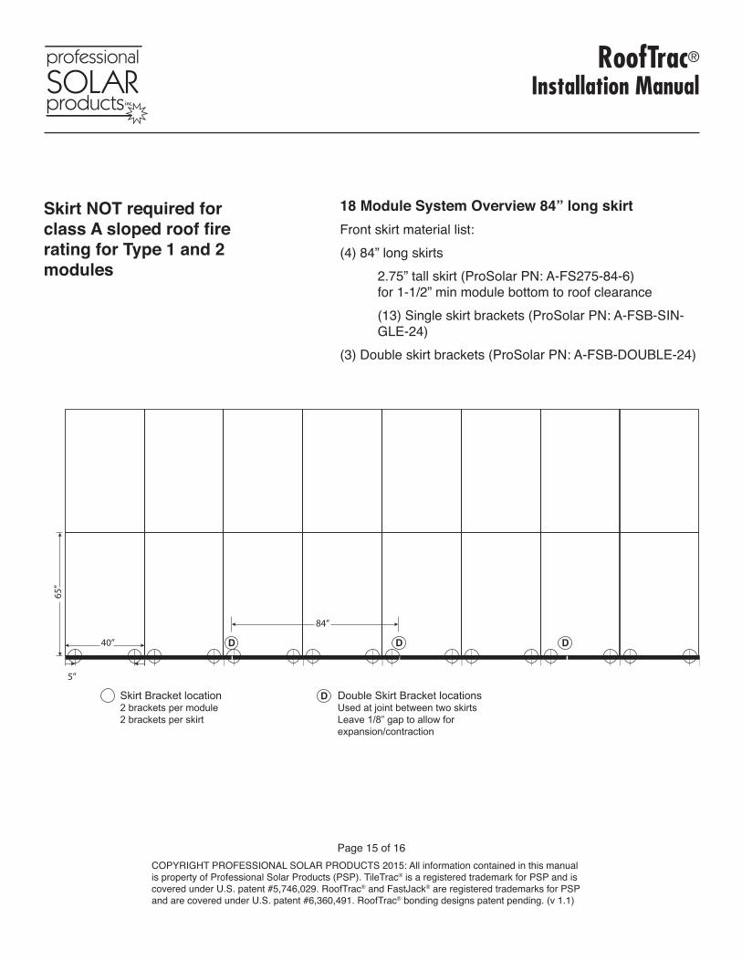
18 Module System Overview 84” long skirtFront skirt material list:(4) 84” long skirts 2.75” tall skirt (ProSolar PN: A-FS275-84-6)
for 1-1/2” min module bottom to roof clearance (13) Single skirt brackets (ProSolar PN: A-FSB-SIN-
GLE-24)(3) Double skirt brackets (ProSolar PN: A-FSB-DOUBLE-24)
Skirt NOT required for class A sloped roof fire rating for Type 1 and 2 modules
5”
65”
40”
84”
Skirt Bracket location2 brackets per module2 brackets per skirt
Double Skirt Bracket locationsUsed at joint between two skirtsLeave 1/8” gap to allow for expansion/contraction
D D
D
D
RoofTrac®
Installation Manual
Page 16 of 16COPYRIGHT PROFESSIONAL SOLAR PRODUCTS 2015: All information contained in this manual is property of Professional Solar Products (PSP). TileTrac® is a registered trademark for PSP and is covered under U.S. patent #5,746,029. RoofTrac® and FastJack® are registered trademarks for PSP and are covered under U.S. patent #6,360,491. RoofTrac® bonding designs patent pending. (v 1.1)
B Bonding 6, 9, 11, 12, 13
CCantilever 8 Channel Nut with bus bar 2, 11 without bus bar 2, 6, 12
D Drill rail 6
E End Clamp 2, 9, 10 F FastJack® 2, 3, 4, 8 Flashing 2, 3, 4
G Grounding 11, 12Grounding diagram 12
I Ilsco 2, 11, 12Impact gun (mechanical) 4, 8
LLoad rating 3
M Malco TurboShear 2, 4 Marking rail 8Microinverter bonding 13 Mid Clamp 2, 9, 10, 11, 12Module install 10Modules(Compatible) 11
OOptimizer bonding 13
PParts list 2 RRail 2, 6-13Rail Span 3RoofTrac® Rail Splice 2, 6, 7, 10, 11 RoofTrac® Rail Spreader 9, 10 Rotary Hammer Drill 5
S Sealant 4, 5 Skirt 14, 15Sub Flashing 5
T TileTrac® 2, 3, 5Tool list 1Torque Values 2
U UL 1703 1, 3 UL 2703 6, 10, 11 UL 467 6, 11 Unibit® 6, 8
W Wire Management 13
Index