rooftop unit, heat pump and indoor air quality application ......
TRANSCRIPT
Rooftop Unit, Heat Pump and Indoor Air Quality Application GuideVT8600 Series Room Controllers
TABLE OF CONTENTSOverview 2VT8600 Rooftop Unit Heat Pump and Indoor Air Quality Controllers 3VT86X0U5X00B Heating / 2 Cooling for Rootop Unit and Indoor Air Quality 4VT86X0U5X00B Cooling / Modulating Heat for Rootop Unit and Indoor Air Quality 6Fresh Air Damper Control Sequences 8Economizer Control Only 8Economizer Control Mode and Fresh Air Measurement Station 9Economize Control Mode and CO2 Level Control 10Economizer Control Mode, CO2 Level Control and Fresh Air Measurement Station 11Appendix A - Passive infra-red (PIR) motion detector cover specifications 12Appendix B - Optional Network Set-Up 13Appendix C - Controllers’ Occupancy Sequence of Operation Schematic 13Appendix D - SED Series - wireless door & window switch 14

VT8600 Rooftop, Heat Pump and Indoor Air Quality ControllerApplication Guide2
Viconics Technologies Inc. | 9245 Langelier Blvd. | St.-Leonard | Quebec | Canada | H1P 3K9 | Tel: (514) 321-5660 | Fax: (514) 321-4150 028-6085-01 www.viconics.com | [email protected] April 201
© 2
015
Vic
onci
s Te
chno
logi
es. A
ll rig
hts
rese
rved
.
OVERVIEWVT8600
The VT8600 Rooftop, Heat Pump and Indoor Air Quality Controller is cost-effective solution for upgrading rooftop unit thermostats. The application allows existing wiring between the rooftop unit and the Room Controller to be re-used, reducing overall costs and installation time. The VT8600 can also add features like CO2 and fresh air monitoring to the existing functions of a rooftop unit.
The VT8600 Rooftop, Heat Pump, and Indoor Air Quality Controller can be configured to handle a broad variety of applications covering all the standard implementations necessary for rooftop HVAC systems.
In addition to controlling heating, cooling and air quality, depending on the model and accessories, the VT8600 can handle wireless networking and switches, Passive Infrared (PIR) occupancy detection using either onboard or remote sensors, and can have custom programs implemented to fulfill specific User requirements. The applications described here cover all these features in combination with the VT8600’s advanced scheduling and occupancy controls to provide the functionality for any required rooftop HVAC implementation.
3
Viconics Technologies Inc. | 9245 Langelier Blvd. | St.-Leonard | Quebec | Canada | H1P 3K9 | Tel: (514) 321-5660 | Fax: (514) 321-4150 028-6085-01 www.viconics.com | [email protected] April 201
Application Guide
© 2
015
Vic
onci
s Te
chno
logi
es. A
ll rig
hts
rese
rved
.
VT8600 Rooftop, Heat Pump and Indoor Air Quality Controller
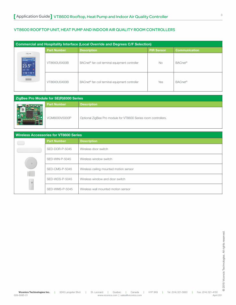
VT8600 ROOFTOP UNIT, HEAT PUMP AND INDOOR AIR QUALITY ROOM CONTROLLERS
ZigBee Pro Module for SE(R)8300 Series
Power
Part Number Description
VCM8000V5000P Optional ZigBee Pro module for VT8600 Series room controllers.
Commercial and Hospitality Interface (Local Override and Degrees C/F Selection)
Power Part Number Description PIR Sensor Communication
VT86X0U5X00B BACnet® fan coil terminal equipment controller No BACnet®
VT86X0U5X00B BACnet® fan coil terminal equipment controller Yes BACnet®
Wireless Accessories for VT8600 Series
Power Part Number Description
SED-DOR-P-5045 Wireless door switch
SED-WIN-P-5045 Wireless window switch
SED-CMS-P-5045 Wireless ceiling mounted motion sensor
SED-WDS-P-5045 Wireless window and door switch
SED-WMS-P-5045 Wireless wall mounted motion sensor

VT8600 Rooftop, Heat Pump and Indoor Air Quality ControllerApplication Guide4
Viconics Technologies Inc. | 9245 Langelier Blvd. | St.-Leonard | Quebec | Canada | H1P 3K9 | Tel: (514) 321-5660 | Fax: (514) 321-4150 028-6085-01 www.viconics.com | [email protected] April 201
© 2
015
Vic
onci
s Te
chno
logi
es. A
ll rig
hts
rese
rved
.
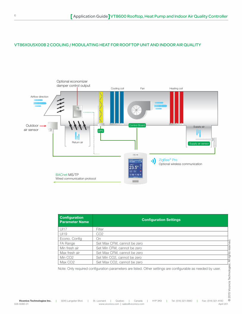
Configuration Parameter Name
Configuration Settings
UI17 FilterUI19 CO2Econo. Config OnFA Range Set Max CFM, cannot be zeroMin fresh air Set Min CFM, cannot be zeroMax fresh air Set Max CFM, cannot be zeroMin CO2 Set Min CO2, cannot be zeroMax CO2 Set Max CO2, cannot be zero
Note: Only required configuration parameters are listed. Other settings are configurable as needed by user.
VT86X0U5X00B 2 HEATING / 2 COOLING FOR ROOFTOP UNIT AND INDOOR AIR QUALITY
Fresh airmeasurement station
Outside air sensor
BACnet MS/TPWired communication protocol
Control Board
Supply air sensor
CO2 air sensor
Outside air
ZigBee® ProOptional wireless communication
Cooling coil Fan Heating coil
Return air
Supply airDPS
Filter
5
Viconics Technologies Inc. | 9245 Langelier Blvd. | St.-Leonard | Quebec | Canada | H1P 3K9 | Tel: (514) 321-5660 | Fax: (514) 321-4150 028-6085-01 www.viconics.com | [email protected] April 201
Application Guide
© 2
015
Vic
onci
s Te
chno
logi
es. A
ll rig
hts
rese
rved
.
VT8600 Rooftop, Heat Pump and Indoor Air Quality Controller
VT8600
BO
1 -
Aux
BO
2 -
Y2
BO
3 -
Y1
BO
4 -
G
RC
(24
Vac)
C (C
omm
on)
RH
BO
8 -
W1
UO
9 -
W2
UO
10
- E
cono
UO
11
- H
eat
UO
12
BA
Cne
t +
BA
Cne
t -
BA
Cne
t RE
F
UI 1
6
UI 1
7
Com
mon
UI 1
9 -
CO
2
UI 2
0 -
RS
Com
mon
UI 2
2 -
SS
UI 2
3 -
OS
UI 2
4 -
Air
flow
13 14 15 16 17 18
7 8 9 10 11 12
19 20 21 22 23 24
1 2 3 4 5 6
ECONO
W2 W1 C R G Y1 Y2
C RCO2
TRANSMITTER(0-10 VDC)
OUT
C OUT
R AIR FLOW
MEASURING STATION (0-10 VDC)
FILTERDPS
SATSENSOR
OATSENSOR
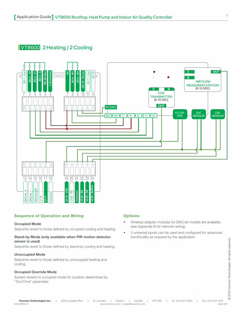
2 Heating / 2 Cooling
Sequence of Operation and Wiring
Occupied ModeSetpoints revert to those defined by occupied cooling and heating.
Stand-by Mode (only available when PIR motion detector sensor is used)Setpoints revert to those defined by stand-by cooling and heating.
Unoccupied ModeSetpoints revert to those defined by unoccupied heating and cooling.
Occupied Override ModeSystem reverts to occupied mode for duration determined by “ToccTime” parameter.
Options
• Wireless adapter modules for BACnet models are available. (see Appendix B for network wiring).
• 3 universal inputs can be used and configured for advanced functionality as required by the application.
VT8600 Rooftop, Heat Pump and Indoor Air Quality ControllerApplication Guide6
Viconics Technologies Inc. | 9245 Langelier Blvd. | St.-Leonard | Quebec | Canada | H1P 3K9 | Tel: (514) 321-5660 | Fax: (514) 321-4150 028-6085-01 www.viconics.com | [email protected] April 201
© 2
015
Vic
onci
s Te
chno
logi
es. A
ll rig
hts
rese
rved
.
Configuration Parameter Name
Configuration Settings
UI17 FilterUI19 CO2Econo. Config OnFA Range Set Max CFM, cannot be zeroMin fresh air Set Min CFM, cannot be zeroMax fresh air Set Max CFM, cannot be zeroMin CO2 Set Min CO2, cannot be zeroMax CO2 Set Max CO2, cannot be zero
Note: Only required configuration parameters are listed. Other settings are configurable as needed by user.
VT86X0U5X00B 2 COOLING / MODULATING HEAT FOR ROOFTOP UNIT AND INDOOR AIR QUALITY
Airflow direction
Return air
Supply air
Optional economizerdamper control output
Outdoorair sensor
BACnet MS/TPWired communication protocol
ZigBee® ProOptional wireless communication
Control Board
Supply air sensor
Cooling coil Fan Heating coil
DPS

7
Viconics Technologies Inc. | 9245 Langelier Blvd. | St.-Leonard | Quebec | Canada | H1P 3K9 | Tel: (514) 321-5660 | Fax: (514) 321-4150 028-6085-01 www.viconics.com | [email protected] April 201
Application Guide
© 2
015
Vic
onci
s Te
chno
logi
es. A
ll rig
hts
rese
rved
.
VT8600 Rooftop, Heat Pump and Indoor Air Quality Controller
13 14 15 16 17 18
7 8 9 10 11 12
VT8600
BO
1 -
Aux
BO
2 -
Y2
BO
3 -
Y1
BO
4 -
G
RC
(24
Vac)
C (C
omm
on)
RH
BO
8 -
W1
UO
9 -
W2
UO
10
- E
cono
UO
11
- H
eat
UO
12
BA
Cne
t +
BA
Cne
t -
BA
Cne
t RE
F
UI 1
6
UI 1
7
Com
mon
UI 1
9 -
CO
2
UI 2
0 -
RS
Com
mon
UI 2
2 -
SS
UI 2
3 -
OS
UI 2
4 -
Air
flow
19 20 21 22 23 24
1 2 3 4 5 6
ECONO
C R G Y1 Y2
C RCO2
TRANSMITTER(0-10 VDC)
OUT
C OUT
R AIR FLOW
MEASURING STATION (0-10 VDC)
FILTERDPS
SATSENSOR
OATSENSOR
Mod. Heat(0-10 VDC)
2 Cooling / Modulating Heat
Sequence of Operation and Wiring
Occupied ModeSetpoints revert to those defined by occupied cooling and heating.
Stand-by Mode (only available when PIR motion detector sensor is used)Setpoints revert to those defined by stand-by cooling and heating.
Unoccupied ModeSetpoints revert to those defined by unoccupied heating and cooling.
Occupied Override ModeSystem reverts to occupied mode for duration determined by “ToccTime” parameter.
Options
• Wireless adapter modules for BACnet models are available. (see Appendix B for network wiring).
• 3 universal inputs can be used and configured for advanced functionality as required by the application.

VT8600 Rooftop, Heat Pump and Indoor Air Quality ControllerApplication Guide8
Viconics Technologies Inc. | 9245 Langelier Blvd. | St.-Leonard | Quebec | Canada | H1P 3K9 | Tel: (514) 321-5660 | Fax: (514) 321-4150 028-6085-01 www.viconics.com | [email protected] April 201
© 2
015
Vic
onci
s Te
chno
logi
es. A
ll rig
hts
rese
rved
.
FRESH AIR DAMPER CONTROL SEQUENCESThe fresh air damper can be controlled through more than one sequence to achieve different control strategies such as free cooling (economizer mode), minimum fresh air control and CO2 level control. Here are the control sequences available:
Note: For the sequences mentioned below, the following conditions must be met in order for the sequences to be performed as stated:
• Max Pos parameter value must be greater than Min Pos Parameter value.
• Mac CO2 parameter value must be greater than Min CO2 Parameter value.
• Max FA parameter value must be greater than Min FA Parameter value.
Economizer Control Mode Only
If the fresh air damper is to be used only for free cooling purposes (economizer mode, without fresh air measurement station or CO2 control), only the Min Pos parameter and the free cooling sequence will be active.
• The FA Range parameter should be set to 0 CFM. (Default Value = 0 CFM)
• Set the Chngstpt parameter to desired value which free cooling is enabled. (Default Value = 55°F)
If the outside air temperature is greater than the changeover setpoint, then normal mechanical cooling will be used. If the outside air temperature is less than or equal to the changeover setpoint, then free cooling will be enabled and mechanical cooling stages will be locked out.
Outside air sensor
BACnet MS/TPWired communication protocol
Control Board
Supply air sensor
Outside air
ZigBee® ProOptional wireless communication
Cooling coil Fan Heating coil
Return air
Supply air

9
Viconics Technologies Inc. | 9245 Langelier Blvd. | St.-Leonard | Quebec | Canada | H1P 3K9 | Tel: (514) 321-5660 | Fax: (514) 321-4150 028-6085-01 www.viconics.com | [email protected] April 201
Application Guide
© 2
015
Vic
onci
s Te
chno
logi
es. A
ll rig
hts
rese
rved
.
VT8600 Rooftop, Heat Pump and Indoor Air Quality Controller
Economizer Control Mode and Fresh Air Measurement Station
If the fresh air damper is to be used for both free cooling and minimum fresh air volume control (economizer mode and fresh air measurement station, but without CO2 level control), only the Min FA parameter and the free cooling sequence will be active.
• The FA Range parameter should be set to a value higher than 0 CFM (0 CFM disables the fresh air control).
• Min FA (minimum fresh air) parameter should be set to the desired level.
The FA Range parameter value should be set to the maximum capacity of the fresh air measurement station. Therefore the relationship between air volumes and input signals can be established. For example, if the fresh air station capacity is 10000 CFM, set FA Range to 10000.
This will set the relationship of 0 VDC = 0 CFM and 10VDC = 10000 CFM.
Fresh airmeasurement station
Outside air sensor
BACnet MS/TPWired communication protocol
Control Board
Supply air sensor
Outside air
ZigBee® ProOptional wireless communication
Cooling coil Fan Heating coil
Return air
Supply air

VT8600 Rooftop, Heat Pump and Indoor Air Quality ControllerApplication Guide10
Viconics Technologies Inc. | 9245 Langelier Blvd. | St.-Leonard | Quebec | Canada | H1P 3K9 | Tel: (514) 321-5660 | Fax: (514) 321-4150 028-6085-01 www.viconics.com | [email protected] April 201
© 2
015
Vic
onci
s Te
chno
logi
es. A
ll rig
hts
rese
rved
.
Economizer Control Mode and CO2 Level Control
If the fresh air damper is to be used for both free cooling and CO2 level control (economizer mode and CO2 level control, but without fresh air measurement station), only the Min Pos, Max Pos, Min CO2 and Max CO2 parameters as well as the free cooling sequence will be active.
• The FA Range parameter should be set to 0 CFM.
• Set AI1 parameter to CO2 (0 VDC = 0ppm ; 10VDC = 2000ppm)
• Min Pos, Max Pos, Min CO2 and Max CO2 parameters should be set according to the required setting.
The highest value between free cooling demand output and interpolation output for the fresh air setpoint will be the output to the fresh air damper.
Outside air sensor
BACnet MS/TPWired communication protocol
Control Board
Supply air sensor
CO2 air sensor
Outside air
ZigBee® ProOptional wireless communication
Cooling coil Fan Heating coil
Return air
Supply air
Max Pos
Current Fresh Air Setpoint
Min Pos
Max CO2Min CO2
Current CO2 Level
11
Viconics Technologies Inc. | 9245 Langelier Blvd. | St.-Leonard | Quebec | Canada | H1P 3K9 | Tel: (514) 321-5660 | Fax: (514) 321-4150 028-6085-01 www.viconics.com | [email protected] April 201
Application Guide
© 2
015
Vic
onci
s Te
chno
logi
es. A
ll rig
hts
rese
rved
.
VT8600 Rooftop, Heat Pump and Indoor Air Quality Controller
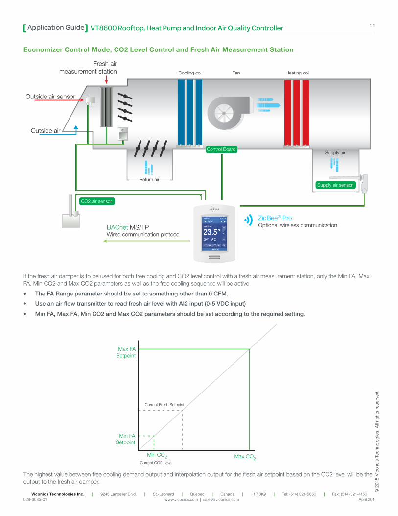
Economizer Control Mode, CO2 Level Control and Fresh Air Measurement Station
If the fresh air damper is to be used for both free cooling and CO2 level control with a fresh air measurement station, only the Min FA, Max FA, Min CO2 and Max CO2 parameters as well as the free cooling sequence will be active.
• The FA Range parameter should be set to something other than 0 CFM.
• Use an air flow transmitter to read fresh air level with AI2 input (0-5 VDC input)
• Min FA, Max FA, Min CO2 and Max CO2 parameters should be set according to the required setting.
The highest value between free cooling demand output and interpolation output for the fresh air setpoint based on the CO2 level will be the output to the fresh air damper.
Fresh airmeasurement station
Outside air sensor
BACnet MS/TPWired communication protocol
Control Board
Supply air sensor
CO2 air sensor
Outside air
ZigBee® ProOptional wireless communication
Cooling coil Fan Heating coil
Return air
Supply air
Max FASetpoint
Current Fresh Setpoint
Min FASetpoint
Max CO2Min CO2
Current CO2 Level

VT8600 Rooftop, Heat Pump and Indoor Air Quality ControllerApplication Guide12
Viconics Technologies Inc. | 9245 Langelier Blvd. | St.-Leonard | Quebec | Canada | H1P 3K9 | Tel: (514) 321-5660 | Fax: (514) 321-4150 028-6085-01 www.viconics.com | [email protected] April 201
© 2
015
Vic
onci
s Te
chno
logi
es. A
ll rig
hts
rese
rved
.
The PIR can maximize your energy saving from 10-30% by relaxing temperature set points in unoccupied zones during scheduled periods.
Typical Savings of 10-30%
05
10152025303540455055606570758085
0 2 4 6 8 10 12 14 16 18 20 22 24
Time of Day (EST)
Ener
gy U
sage
(KW
h)
0%
10%
20%
30%
40%
50%
Saving Percentage
Typical Consumption PIR Thermostat Consumption Savings
APPENDIX A PASSIVE INFRA-RED (PIR) MOTION DETECTOR COVER SPECIFICATIONS
Initially, the controller is in Stand-by mode. Stand-by setpoints are used at the controller. As soon as the PIR detects motion, the Occupancy status switches to Occupied and the Stand-By Time timer is reset. The Occupied setpoints are used. If no motion is detected in the room for the entire Stand-By Time duration (adjustable parameter), the room then switches to Stand-by mode and stand-by setpoints are used. While in Stand-by mode, if no motion is detected for the entire Unoccupied Time period (adjustable parameter), the room switches to Unoccupied mode and uses its Unoccupied setpoints. While in Stand-By or Unoccupied mode, any motion will switch the room back to Occupied mode. For this reason, avoid installing PIR sensors near heat vents or other sources of moving warm air in order to avoid false detections.
PIR cover sequence of operation
Typical Detection Pattern for PIR Lens
Energy savings
20O
20O
20O
20O
40O
A
BB
CC
Horizontal Angles (Typical)
Transverse motion: 4-5 ft/s / 1.5 m/sRecommended installation height for PIR sensor:
4 - 5 ft. / 1.2-1.5 m
Sensor Ranges
A = 20 ft. / 6.1 mB = 14 ft. / 4.3 mC = 11 ft. / 3.4 m
Center
30O
Vertical Angle (Typical)
Center
13
Viconics Technologies Inc. | 9245 Langelier Blvd. | St.-Leonard | Quebec | Canada | H1P 3K9 | Tel: (514) 321-5660 | Fax: (514) 321-4150 028-6085-01 www.viconics.com | [email protected] April 201
Application Guide
© 2
015
Vic
onci
s Te
chno
logi
es. A
ll rig
hts
rese
rved
.
VT8600 Rooftop, Heat Pump and Indoor Air Quality Controller
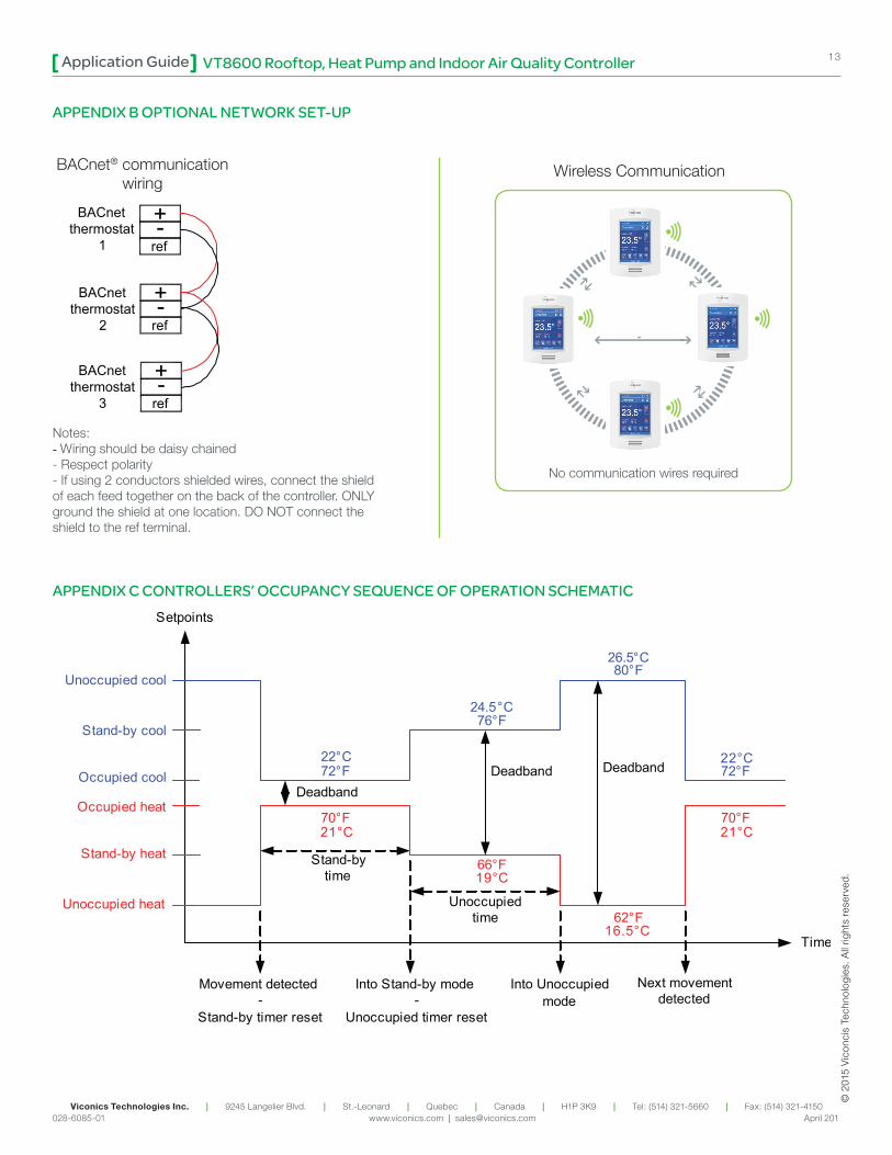
APPENDIX B OPTIONAL NETWORK SET-UP
+-ref
+-ref
+-ref
BACnetthermostat
1
BACnetthermostat
2
BACnetthermostat
3
Notes:- Wiring should be daisy chained- Respect polarity- If using 2 conductors shielded wires, connect the shield of each feed together on the back of the controller. ONLY ground the shield at one location. DO NOT connect the shield to the ref terminal.
APPENDIX C CONTROLLERS’ OCCUPANCY SEQUENCE OF OPERATION SCHEMATICSetpoints
Time
Unoccupied cool
Occupied cool
Stand-by cool
72°F
76°F
80°F
Movement detected-
Stand-by timer reset
Into Stand-by mode-
Unoccupied timer reset
Stand-bytime
Unoccupiedtime
Into Unoccupiedmode
Next movementdetected
70°F
62°FUnoccupied heat
Occupied heat
Stand-by heat
72°F
66°F
70°F
Deadband Deadband
Deadband
22°C
24.5°C
26.5°C
22°C
21°C 21°C
19°C
16.5°C
BACnet® communicationwiring
No communication wires required
Wireless Communication
VT8600 Rooftop, Heat Pump and Indoor Air Quality ControllerApplication Guide14
Viconics Technologies Inc. | 9245 Langelier Blvd. | St.-Leonard | Quebec | Canada | H1P 3K9 | Tel: (514) 321-5660 | Fax: (514) 321-4150 028-6085-01 www.viconics.com | [email protected] April 201
© 2
015
Vic
onci
s Te
chno
logi
es. A
ll rig
hts
rese
rved
.
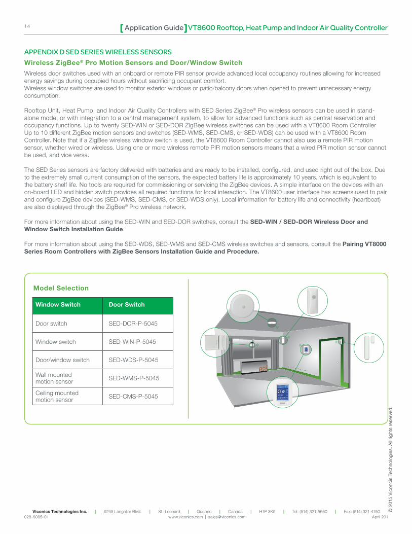
APPENDIX D SED SERIES WIRELESS SENSORSWireless ZigBee® Pro Motion Sensors and Door/Window Switch
Wireless door switches used with an onboard or remote PIR sensor provide advanced local occupancy routines allowing for increased energy savings during occupied hours without sacrificing occupant comfort. Wireless window switches are used to monitor exterior windows or patio/balcony doors when opened to prevent unnecessary energy consumption.
Rooftop Unit, Heat Pump, and Indoor Air Quality Controllers with SED Series ZigBee® Pro wireless sensors can be used in stand-alone mode, or with integration to a central management system, to allow for advanced functions such as central reservation and occupancy functions. Up to twenty SED-WIN or SED-DOR ZigBee wireless switches can be used with a VT8600 Room ControllerUp to 10 different ZigBee motion sensors and switches (SED-WMS, SED-CMS, or SED-WDS) can be used with a VT8600 Room Controller. Note that if a ZigBee wireless window switch is used, the VT8600 Room Controller cannot also use a remote PIR motion sensor, whether wired or wireless. Using one or more wireless remote PIR motion sensors means that a wired PIR motion sensor cannot be used, and vice versa.
The SED Series sensors are factory delivered with batteries and are ready to be installed, configured, and used right out of the box. Due to the extremely small current consumption of the sensors, the expected battery life is approximately 10 years, which is equivalent to the battery shelf life. No tools are required for commissioning or servicing the ZigBee devices. A simple interface on the devices with an on-board LED and hidden switch provides all required functions for local interaction. The VT8600 user interface has screens used to pair and configure ZigBee devices (SED-WMS, SED-CMS, or SED-WDS only). Local information for battery life and connectivity (heartbeat) are also displayed through the ZigBee® Pro wireless network.
For more information about using the SED-WIN and SED-DOR switches, consult the SED-WIN / SED-DOR Wireless Door and Window Switch Installation Guide.
For more information about using the SED-WDS, SED-WMS and SED-CMS wireless switches and sensors, consult the Pairing VT8000 Series Room Controllers with ZigBee Sensors Installation Guide and Procedure.
Window Switch Door Switch
Door switch SED-DOR-P-5045
Window switch SED-WIN-P-5045
Door/window switch SED-WDS-P-5045
Wall mounted motion sensor SED-WMS-P-5045
Ceiling mounted motion sensor SED-CMS-P-5045
Model Selection

15
Viconics Technologies Inc. | 9245 Langelier Blvd. | St.-Leonard | Quebec | Canada | H1P 3K9 | Tel: (514) 321-5660 | Fax: (514) 321-4150 028-6085-01 www.viconics.com | [email protected] April 201
Application Guide
© 2
015
Vic
onci
s Te
chno
logi
es. A
ll rig
hts
rese
rved
.
VT8600 Rooftop, Heat Pump and Indoor Air Quality Controller
APPENDIX E TERMINAL CORRESPONDENCE The terminals of an VT8600 are identified differently and have a wider range of possible functions compared to those of any of the VT7000 series Room Controllers. Nonetheless, there is a direct correspondence of functions between the terminals of the VT7000 series and the VT8600 series. Consult the table below to verify the appropriate terminal when replacing a VT7000 Room Controller with a VT8600 Room Controller.
VT7000 VT8600
Terminal name Terminal ID Terminal name Terminal ID
Binary Input 1 BI1 Universal Input 16 UI16
Binary Input 2 BI2 Universal Input 17 UI17
Universal Input 3 UI3 Universal Input 19 UI19
Sensor Common Scom Terminal 18 Common COM
Remote Sensor RS Universal Input 20 UI20 - RS
Sensor Common Scom Terminal 21 Common COM
Mix/Supply Sensor MS Universal Input 22 UI22 - SS
LED
Hidden switch
SED-WIN SED-DOR
Hidden switch
Hidden switch
Hidden switch
LED
LEDLED
SED-WMSSED-CMS
SED-WDS