roof water harvisting 2002
TRANSCRIPT
8/3/2019 Roof Water Harvisting 2002
http://slidepdf.com/reader/full/roof-water-harvisting-2002 1/25
Domestic Roofwater Harvesting
Research Programme
Development Technology Unit
School of Engineering, University of Warwick
NEW TECHNOLOGY FORVERY-LOW-COST
DOMESTIC ROOFWATER HARVESTING
DFID KaR Contract R7833
April 2002

8/3/2019 Roof Water Harvisting 2002
http://slidepdf.com/reader/full/roof-water-harvisting-2002 2/25
R7833 Roofwater Harvesting for Poorer Households in the Tropics
New Technology for Very-Low-Cost Roofwater Harvesting 1
CONTENTS
1 INTRODUCTION .............................................................................................................................2
1.1 The need......................................................................................................................................2
1.2 Methods of cost reduction...........................................................................................................3
1.3 Basis for cost comparison ...........................................................................................................3
2 TANKS .............................................................................................................................................4
2.1 Current state-of-the-art................................................................................................................4
2.2 Below-ground designs.................................................................................................................5
2.3 Above-ground designs ..............................................................................................................10
3 ROOFS...........................................................................................................................................14
4 GUTTERS ......................................................................................................................................15
5 CONCLUSION ...............................................................................................................................16
6 BIBLIOGRAPHY............................................................................................................................17
8/3/2019 Roof Water Harvisting 2002
http://slidepdf.com/reader/full/roof-water-harvisting-2002 3/25
R7833 Roofwater Harvesting for Poorer Households in the Tropics
New Technology for Very-Low-Cost Roofwater Harvesting 2
1 INTRODUCTION
This report is an output from a 27 month research contract (R7833) for the UK
Department for International Development and describes work done during the 4month prototyping phase of that project. The prototyping phase has developed out of the practice
descried in the report to the DFID “R1, Very-Low-Cost Domestic Roofwater Harvesting in the Humid
Tropics: Existing Practice” and the constraints identified in “R2, Very-Low-Cost Domestic Roofwater
Harvesting in the Humid Tropics: Constraints and Problems”. The work itself was carried out by the
DTU along with members of the Lanka Rainwater Harvesting Forum in Sri Lanka, Water Action in
Ethiopia and ACORD in Uganda.
The Sri Lankan portion of this work would not have been possible without the facilities and kind
assistance of the Nation Builders Association. In particular we would like to thank Mr Adikarum, Mr
Amarasinge, Mr Widasecara and Mr Siripala for their help, insight and patience during our time there.
1.1 The need
Surveys carried out in the initial phase of the project have pointed to cost as the number one constraint
facing users adopting roofwater harvesting so if it is to become an affordable option for poor people in
developing countries, the cost of systems must be reduced.
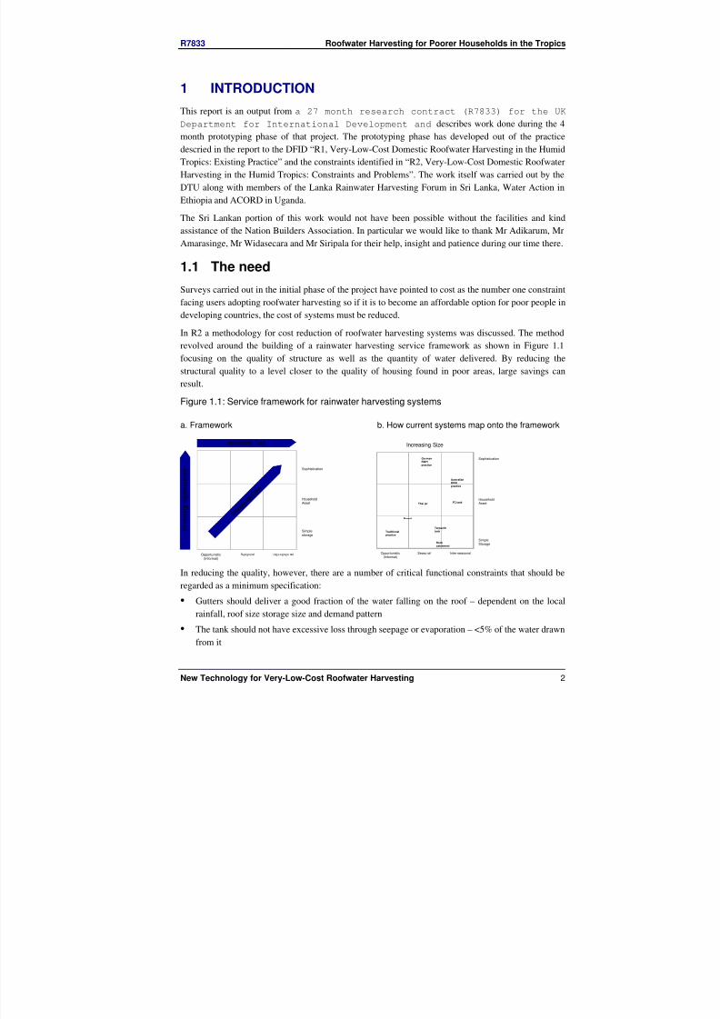
In R2 a methodology for cost reduction of roofwater harvesting systems was discussed. The method
revolved around the building of a rainwater harvesting service framework as shown in Figure 1.1
focusing on the quality of structure as well as the quantity of water delivered. By reducing the
structural quality to a level closer to the quality of housing found in poor areas, large savings can
result.
Figure 1.1: Service framework for rainwater harvesting systems
a. Framework
Simplestorage
Household
Asset
Sophistication
I n c r e a s i n g
S o p h i s t i c a t i o n
Increasing Size
Opportunistic(Informal)
Seasonal Inter-seaso nal
I n c r e a s
i n g C o
s t
b. How current systems map onto the framework
Increasing Size
SimpleStorage
Household
Asset
Sophistication
Opportunistic(Informal)
Seasonal Inter-seasonal
Traditional
practice
Barrel
Thai jarFC tank
German
RWH
practice
Tarpaulin
tank
Australian
RWH
practice
Rock
catchment
In reducing the quality, however, there are a number of critical functional constraints that should be
regarded as a minimum specification:
• Gutters should deliver a good fraction of the water falling on the roof – dependent on the local
rainfall, roof size storage size and demand pattern
• The tank should not have excessive loss through seepage or evaporation – <5% of the water drawnfrom it
8/3/2019 Roof Water Harvisting 2002
http://slidepdf.com/reader/full/roof-water-harvisting-2002 4/25
R7833 Roofwater Harvesting for Poorer Households in the Tropics
New Technology for Very-Low-Cost Roofwater Harvesting 3
• The tank should not present an excessive danger to its users, either by their falling in or by the
tank failing violently
• The water must be of a quality consummate with its intended use – water that is used for drinking
requires a certain care in transport and storage:
– The catchment area should be smooth and free from accumulated debris– The water should be filtered to remove gross impurities or the first flush removed
– The tank should be covered to prevent entry of light, and sealed against intrusion by vermin
– The tank should be ventilated to prevent anaerobic decomposition of any washed-in matter
1.2 Methods of cost reduction
The methods used to reduce the cost of rainwater harvesting systems are covered in report R2, the
methods described are:
• Material reduction (Improved formwork, Shape optimisation, Function separation)
• Material substitution (Using cheaper materials, use of “free” materials)
• Mass production
• Use of existing containers
1.3 Basis for cost comparison
Costing “rainwater harvesting systems for the poor” is more complex than simply adding up
component costs on a bill of materials. Some materials are only available at a cost through purchasing
channels, while others are available at no cost if one is willing to gather them. This report will group
materials and labour into the following categories:
a. Economic materials; materials relying on industrial processes – in their purchase cash will be
removed from the area
b. Local economic materials; materials which must be bought but where production is from local
sources – the cash will remain in the community
c. Skilled labour ; labour that must be paid for
d. Local materials; materials that can be gathered from the land – they may or may not have an
economic value but tend to be freely available
e. Householder labour ; labour that can be provided by the household – it may be skilled, but in
locally used techniques (such as wattle and daub construction).
For the poor the latter two costs may be heavily discounted when compared to any cash outgoings, and
consequently they will be are separated from the first three 3 in costings presented in this report.
Household labour is often ignored in costing programmes aimed at the poor, however this may
become unrealistic if the household labour contribution becomes burdensome. Another approach is to
allocate an opportunity cost of 50% of the unskilled labour rate to such a contribution to reflect the
loss of time to the household. The real value of their time to a householder should lie between these
two figures, so both will be quoted in this report They are referred to as “HH labour discounted” cost
and “HH labour ignored” cost. A total cost with no discounting is also included for reference.
8/3/2019 Roof Water Harvisting 2002
http://slidepdf.com/reader/full/roof-water-harvisting-2002 5/25
R7833 Roofwater Harvesting for Poorer Households in the Tropics
New Technology for Very-Low-Cost Roofwater Harvesting 4
2 TANKS
2.1 Current state-of-the-art
Current practice is comprehensively described in report R1 so only a brief summary of current best
practice will be given here as a baseline from which to judge new developments. Water storage forms
the largest single cost component of a RWH system and so is the most likely candidate for cost
reduction. Current state-of-the-art for storage tanks in developing countries is ferrocement
construction, either based on a fixed solid mould or on an open framework. Generally, a solid mould
results in a cheaper tank, as the wall thickness of the tank can be more tightly controlled and work is
done against an inflexible surface. Open frameworks have the advantage of allowing greater flexibility
in tank size but at the cost of plastering work taking place against an elastic backing which lets some
mortar through resulting in greater and more variable wall thickness and a higher cost per tank. Tanks
are also made from bricks which can reduce costs by material substitution but the savings are often not
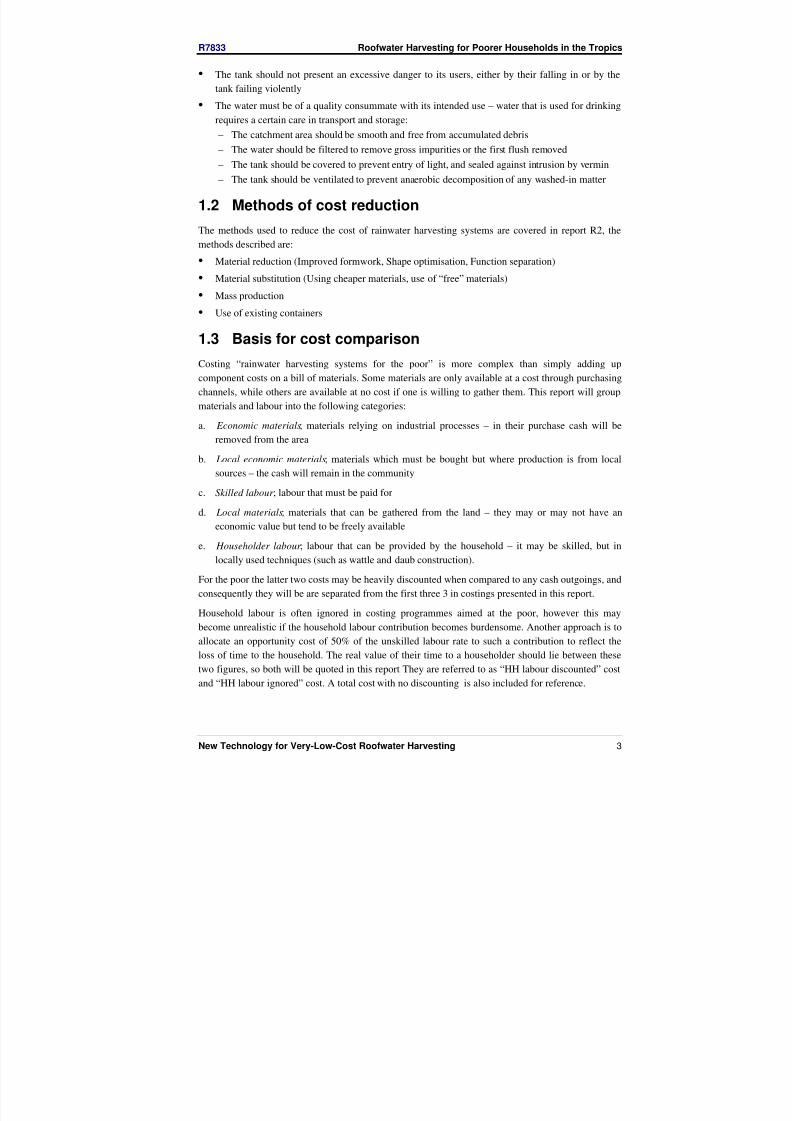
great although more of the money remains in the community. A graph of current costs of various
techniques in the three study countries is given in Figure 2.1.
Figure 2.1: Tank costs
£1
£10
£100
£1,000
0.1 1 10 100
capacity (m3)
U n i t C o s t ( £ / m 3 )
Sri Lanka Uganda Ethiopia
Notes: Points represent costs with household labour discounted, error bars represent the extremities when household labour isincluded in full or ignored altogether
Lines slopes correspond to a cost:capacity sensitivity of 0.6
A cost sensitivity to volume of 0.6 – 0.7 is the norm, so designs can be usefully compared over a wide
range of capacities. The Solid blue lines represent the bounds of normal state-of-the-art. the dotted red
line represents the lower limit of a region populated by “exceptional” designs such as the Thai jar and
the Ugandan tarpaulin tank. It is this region that forms the target cost range. Tanks developed duringthe prototyping phase of the programme fall mainly into the benchmark range as shown in Figure 2.2.

8/3/2019 Roof Water Harvisting 2002
http://slidepdf.com/reader/full/roof-water-harvisting-2002 6/25
R7833 Roofwater Harvesting for Poorer Households in the Tropics
New Technology for Very-Low-Cost Roofwater Harvesting 5
Most of the designs also have a greater reliance on household labour and local materials so
compulsory cash costs are kept lower still (as indicated by the bottom extent of the error bars).
Figure 2.2: cost comparison of tanks developed during the prototyping phase
£1
£10
£100
0.1 1 10
Capacity (m3)
U n
i t C o s t ( £ / m 3 )
PBG (E) PBG (U) PBG (SL) Mud (E) Mud (U)
Mud (SL) Crate (E) Crate (U) Crate (SL) Tube (E)
Tube (U) Tube (SL) Tube - trench (E) Tube -trench (U) Tube -trench (SL)
Thach UG (E) Thatch UG (U) Thatch UG (SL) Joined Drums (E)
2.2 Below-ground designs
Below ground designs are the mainstay of low cost tank design. If built in stable soil, the ground itself
will act as a stiff spring taking much of the load, reducing the role of the lining material to
waterproofing. In these circumstances, tank wall thicknesses can be very small and materials that have
good waterproofing properties but suffer from a low structural strength (such as polyethylene sheet)can be used.
Tube tank
The tube tank was originally developed by the DTU in July 2000 (Rees & Whitehead, 2000), as part
of a technology development project funded in part by the Morris Laing Foundation. The design was
based around a widely available plastic tube of about 500 microns thickness sold by the metre on a roll
of 3ft width. The cost of this tube is £0.38 in Sri Lanka, £0.54 in Ethiopia and £0.40 in Uganda. When
opened, the tube forms a cylinder of Ø54cm resulting in a volume of 0.23m 3 per metre length. The
cost of storage, is therefore only £1.66, £2.33, £1.75 (SL, Et, Ug) per m 3 of storage for the tube itself.
The original design (see Figure 2.3) was based on the partially below ground principle where most of the tank was below ground, but about 1m protruded as a brick parapet, avoiding stormwater ingress
8/3/2019 Roof Water Harvisting 2002
http://slidepdf.com/reader/full/roof-water-harvisting-2002 7/25
R7833 Roofwater Harvesting for Poorer Households in the Tropics
New Technology for Very-Low-Cost Roofwater Harvesting 6
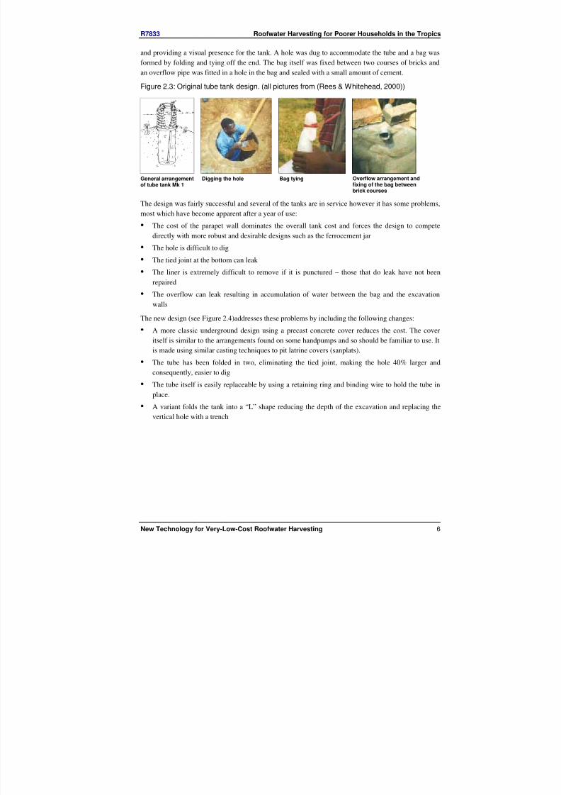
and providing a visual presence for the tank. A hole was dug to accommodate the tube and a bag was
formed by folding and tying off the end. The bag itself was fixed between two courses of bricks and
an overflow pipe was fitted in a hole in the bag and sealed with a small amount of cement.
Figure 2.3: Original tube tank design. (all pictures from (Rees & Whitehead, 2000))
General arrangementof tube tank Mk 1
Digging the hole Bag tying Overflow arrangement andfixing of the bag betweenbrick courses
The design was fairly successful and several of the tanks are in service however it has some problems,
most which have become apparent after a year of use:
• The cost of the parapet wall dominates the overall tank cost and forces the design to compete
directly with more robust and desirable designs such as the ferrocement jar
• The hole is difficult to dig
• The tied joint at the bottom can leak
• The liner is extremely difficult to remove if it is punctured – those that do leak have not been
repaired
• The overflow can leak resulting in accumulation of water between the bag and the excavationwalls
The new design (see Figure 2.4)addresses these problems by including the following changes:
• A more classic underground design using a precast concrete cover reduces the cost. The cover
itself is similar to the arrangements found on some handpumps and so should be familiar to use. It
is made using similar casting techniques to pit latrine covers (sanplats).
• The tube has been folded in two, eliminating the tied joint, making the hole 40% larger and
consequently, easier to dig
• The tube itself is easily replaceable by using a retaining ring and binding wire to hold the tube in
place.
• A variant folds the tank into a “L” shape reducing the depth of the excavation and replacing the
vertical hole with a trench
8/3/2019 Roof Water Harvisting 2002
http://slidepdf.com/reader/full/roof-water-harvisting-2002 8/25
R7833 Roofwater Harvesting for Poorer Households in the Tropics
New Technology for Very-Low-Cost Roofwater Harvesting 7
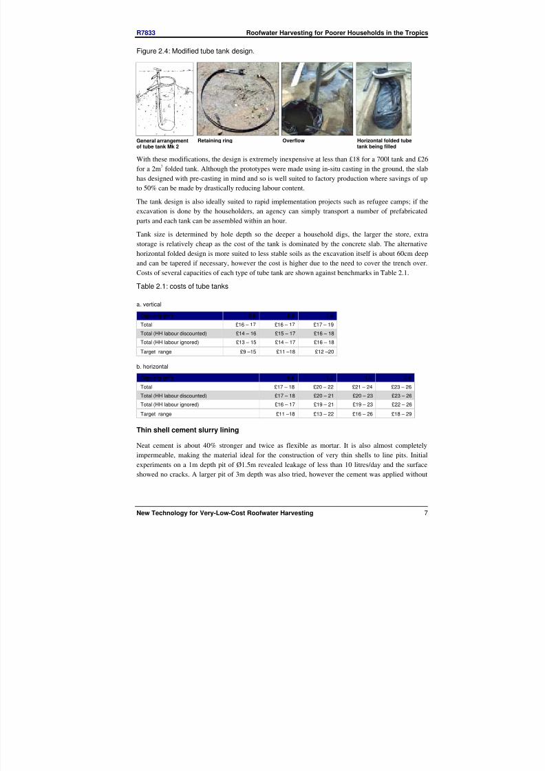
Figure 2.4: Modified tube tank design.
General arrangementof tube tank Mk 2
Retaining ring Overflow Horizontal folded tubetank being filled
With these modifications, the design is extremely inexpensive at less than £18 for a 700l tank and £26
for a 2m3 folded tank. Although the prototypes were made using in-situ casting in the ground, the slab
has designed with pre-casting in mind and so is well suited to factory production where savings of up
to 50% can be made by drastically reducing labour content.The tank design is also ideally suited to rapid implementation projects such as refugee camps; if the
excavation is done by the householders, an agency can simply transport a number of prefabricated
parts and each tank can be assembled within an hour.
Tank size is determined by hole depth so the deeper a household digs, the larger the store, extra
storage is relatively cheap as the cost of the tank is dominated by the concrete slab. The alternative
horizontal folded design is more suited to less stable soils as the excavation itself is about 60cm deep
and can be tapered if necessary, however the cost is higher due to the need to cover the trench over.
Costs of several capacities of each type of tube tank are shown against benchmarks in Table 2.1.
Table 2.1: costs of tube tanks
a. vertical
Capacity (m3) 0.6 0.8 1.0
Total £16 – 17 £16 – 17 £17 – 19
Total (HH labour discounted) £14 – 16 £15 – 17 £16 – 18
Total (HH labour ignored) £13 – 15 £14 – 17 £16 – 18
Target range £9 –15 £11 –18 £12 –20
b. horizontal
Capacity (m3) 0.8 1.2 1.6 2.0
Total £17 – 18 £20 – 22 £21 – 24 £23 – 26
Total (HH labour discounted) £17 – 18 £20 – 21 £20 – 23 £23 – 26
Total (HH labour ignored) £16 – 17 £19 – 21 £19 – 23 £22 – 26
Target range £11 –18 £13 – 22 £16 – 26 £18 – 29
Thin shell cement slurry lining
Neat cement is about 40% stronger and twice as flexible as mortar. It is also almost completely
impermeable, making the material ideal for the construction of very thin shells to line pits. Initial
experiments on a 1m depth pit of Ø1.5m revealed leakage of less than 10 litres/day and the surface
showed no cracks. A larger pit of 3m depth was also tried, however the cement was applied without

8/3/2019 Roof Water Harvisting 2002
http://slidepdf.com/reader/full/roof-water-harvisting-2002 9/25
R7833 Roofwater Harvesting for Poorer Households in the Tropics
New Technology for Very-Low-Cost Roofwater Harvesting 8
due care and cracks developed. The leakage from this pit is 80 litres/day, however no additional
cracking has been observed as a result of the significant head of water acting on the shell.
The thin shell cement lining technique can result in material economies of up to 50% when compared
to conventional mortaring, however the care with which it must be applied to the soil may make it
unsuitable to unsupervised (free market) construction at a local level.
Direct application of mortar
It is common practice to put mesh in an underground tank when lining with mortar. Typically this
takes the form of a layer or two of chicken wire. The given reasons are that it:
• adds strength
• provides a surface upon which to plaster (lath)
• Reduces cracking
Looking at the first of these reasons, a single layer of chicken mesh will have an in-line volume
fraction less than 0.2% when compared to the mortar (assuming a 1cm mortar layer), so itscontribution to the strength of the composite is fairly minimal (about 20% using the law of mixtures).
Of course, the strength of an underground tank is mostly from the reaction of the soil itself.
The second may be true, but the initial layer of mortar is usually applied to the hole adding the mesh
(indeed placing mesh directly on the soil is risky as it will certainly corrode from contact with moist
soil). Further layers can be built up by scoring the original thus providing keys in the mortar itself.
Such scoring is also simple to add to a hard soil and should provide a good keying for mortaring.
Crack reduction can be a useful property, particularly in tanks with large surface areas, however in
smaller, domestic tanks cracking is not big problem as witness the popularity of mortar tanks in
Thailand.
Thus the supposed advantages of using mesh may be insubstantial in this application and are certainly
small compared to the advantages of using the strength of the soil wall.
Conversely, the mesh itself will cause problems when added to a concave surface such as the inside of
a hole. The problem is basically one of overconstraint. If one considers, for the sake of argument a
flexible sheet placed inside a cylinder. It can be either just the right size, too small or too big. If it is
too big, the loose mesh forms bubbles, losing the benefit of the earth wall's support, if it is too tight it
will stretch tight across the wall rather than following the curve, resulting in voids. Adding fixing
points is the usual solution to these difficulties but this often simply turns one large problem into
several small ones. The more fixings, the better the fit but also the greater likelihood of human error –the result can even be areas of too tight mesh next to bubbles of too loose mesh.
Directly applying mortar to the walls has proven to be a simple technique to apply in the field. A thin
layer of 1cm can be applied with ease and with good quality control. The mortar itself has no need for
high strength so can be as lean as 1:8 (cement:sand) in a good soil. Waterproofing is provided by a
thin cement slurry applied while the mortar is wet. Several tanks have been built using this method to
depths of up to 2.5 meters with no visible cracking and lower leakage than evaporation. The direct
application of lean mortar with a slurry coat is the basis for two interrelated designs of tank, the
below-ground cement tank with a cheap roof based on organic material and the partially below ground
tank with a ferrocement dome.
8/3/2019 Roof Water Harvisting 2002
http://slidepdf.com/reader/full/roof-water-harvisting-2002 10/25
R7833 Roofwater Harvesting for Poorer Households in the Tropics
New Technology for Very-Low-Cost Roofwater Harvesting 9
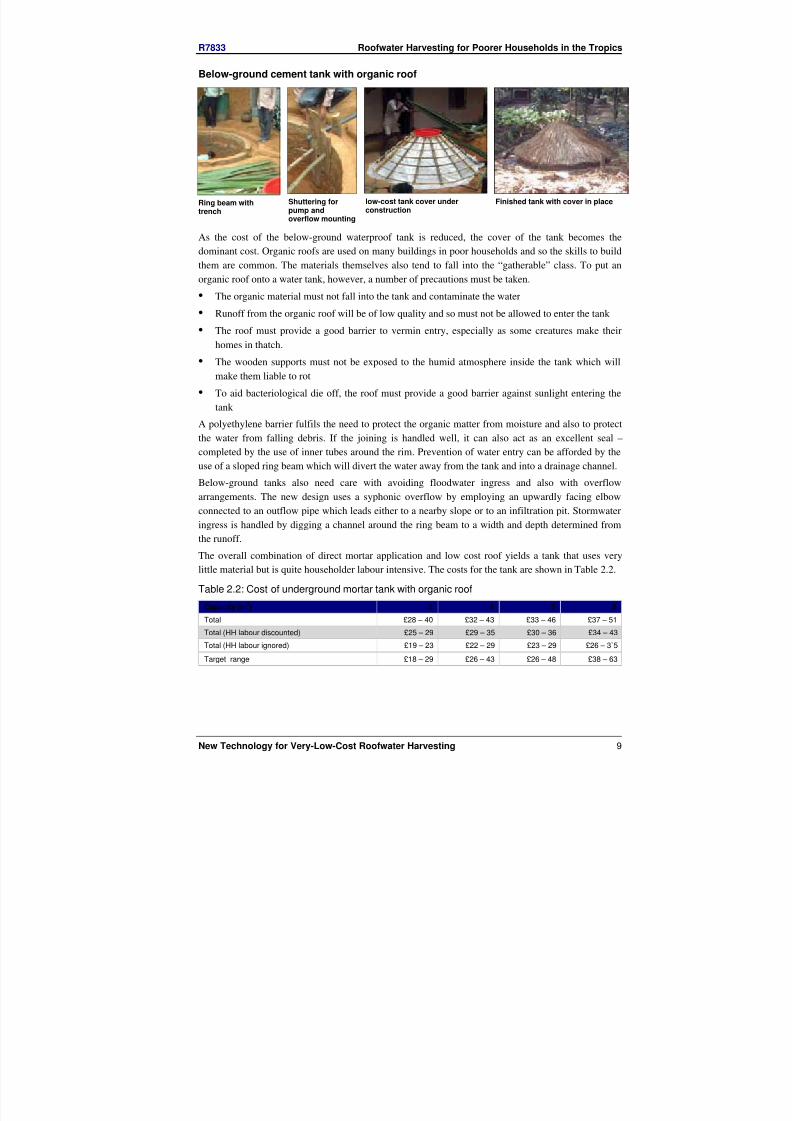
Below-ground cement tank with organic roof
Ring beam withtrench
Shuttering forpump andoverflow mounting
low-cost tank cover underconstruction
Finished tank with cover in place
As the cost of the below-ground waterproof tank is reduced, the cover of the tank becomes the
dominant cost. Organic roofs are used on many buildings in poor households and so the skills to build
them are common. The materials themselves also tend to fall into the “gatherable” class. To put an
organic roof onto a water tank, however, a number of precautions must be taken.
• The organic material must not fall into the tank and contaminate the water
• Runoff from the organic roof will be of low quality and so must not be allowed to enter the tank
• The roof must provide a good barrier to vermin entry, especially as some creatures make their
homes in thatch.
• The wooden supports must not be exposed to the humid atmosphere inside the tank which will
make them liable to rot
• To aid bacteriological die off, the roof must provide a good barrier against sunlight entering the
tank
A polyethylene barrier fulfils the need to protect the organic matter from moisture and also to protect
the water from falling debris. If the joining is handled well, it can also act as an excellent seal –
completed by the use of inner tubes around the rim. Prevention of water entry can be afforded by the
use of a sloped ring beam which will divert the water away from the tank and into a drainage channel.
Below-ground tanks also need care with avoiding floodwater ingress and also with overflow
arrangements. The new design uses a syphonic overflow by employing an upwardly facing elbow
connected to an outflow pipe which leads either to a nearby slope or to an infiltration pit. Stormwater
ingress is handled by digging a channel around the ring beam to a width and depth determined from
the runoff.
The overall combination of direct mortar application and low cost roof yields a tank that uses verylittle material but is quite householder labour intensive. The costs for the tank are shown in Table 2.2.
Table 2.2: Cost of underground mortar tank with organic roof
Capacity (m3) 2 4 5 8
Total £28 – 40 £32 – 43 £33 – 46 £37 – 51
Total (HH labour discounted) £25 – 29 £29 – 35 £30 – 36 £34 – 43
Total (HH labour ignored) £19 – 23 £22 – 29 £23 – 29 £26 – 3`5
Target range £18 – 29 £26 – 43 £26 – 48 £38 – 63
8/3/2019 Roof Water Harvisting 2002
http://slidepdf.com/reader/full/roof-water-harvisting-2002 11/25
R7833 Roofwater Harvesting for Poorer Households in the Tropics
New Technology for Very-Low-Cost Roofwater Harvesting 10
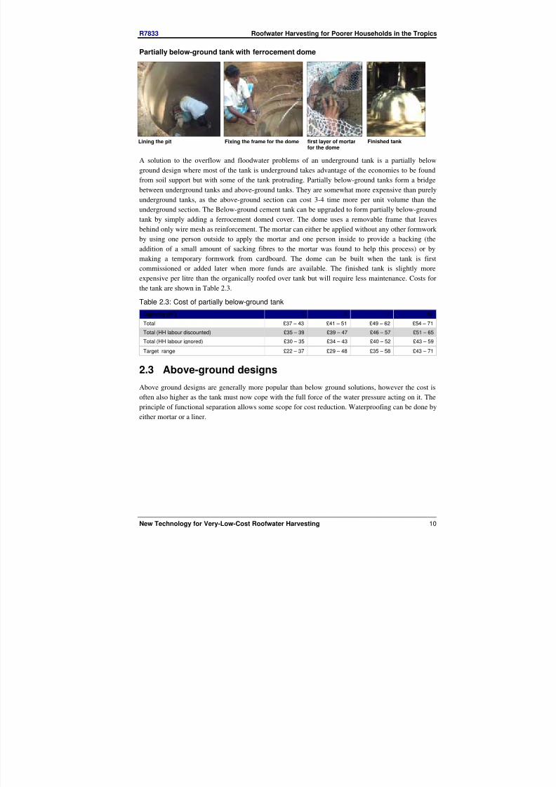
Partially below-ground tank with ferrocement dome
Lining the pit Fixing the frame for the dome first layer of mortarfor the dome
Finished tank
A solution to the overflow and floodwater problems of an underground tank is a partially below
ground design where most of the tank is underground takes advantage of the economies to be found
from soil support but with some of the tank protruding. Partially below-ground tanks form a bridge
between underground tanks and above-ground tanks. They are somewhat more expensive than purely
underground tanks, as the above-ground section can cost 3-4 time more per unit volume than the
underground section. The Below-ground cement tank can be upgraded to form partially below-ground
tank by simply adding a ferrocement domed cover. The dome uses a removable frame that leaves
behind only wire mesh as reinforcement. The mortar can either be applied without any other formwork
by using one person outside to apply the mortar and one person inside to provide a backing (the
addition of a small amount of sacking fibres to the mortar was found to help this process) or by
making a temporary formwork from cardboard. The dome can be built when the tank is first
commissioned or added later when more funds are available. The finished tank is slightly more
expensive per litre than the organically roofed over tank but will require less maintenance. Costs for
the tank are shown in Table 2.3.Table 2.3: Cost of partially below-ground tank
Capacity (m3) 3 5 7 10
Total £37 – 43 £41 – 51 £49 – 62 £54 – 71
Total (HH labour discounted) £35 – 39 £39 – 47 £46 – 57 £51 – 65
Total (HH labour ignored) £30 – 35 £34 – 43 £40 – 52 £43 – 59
Target range £22 – 37 £29 – 48 £35 – 58 £43 – 71
2.3 Above-ground designs
Above ground designs are generally more popular than below ground solutions, however the cost isoften also higher as the tank must now cope with the full force of the water pressure acting on it. The
principle of functional separation allows some scope for cost reduction. Waterproofing can be done by
either mortar or a liner.

8/3/2019 Roof Water Harvisting 2002
http://slidepdf.com/reader/full/roof-water-harvisting-2002 12/25
R7833 Roofwater Harvesting for Poorer Households in the Tropics
New Technology for Very-Low-Cost Roofwater Harvesting 11
Fabric tank
end of fabric tank withbracket
top sheet showing rubberseal
completed fabrictank
An above-ground tank is almost essential in poor crowded urban areas as the ground can be very
contaminated. Ideally, a tank should also be fairly portable as tenure in such communities can often be
insecure and many squatter communities live under constant threat of being moved on. The fabric tank
goes some way to fulfilling these needs by providing a tank with a small footprint, protruding only
45cm from the dwelling. The tank can also be collapsed down into a long, thin package for transport.
A polyethylene tube is placed within a fabric sleeve which is hung on a framework. The fabric takes
the pressure load while the polyethylene provides waterproofing.
Unfortunately, the tank has proved problematic as the fabric itself stretches and puts high loads on its
fixings which then fail. The fixings could be made stronger and more expensive fabrics should stretch
less, however they will make the tank unaffordable.
Crate tank
lid with hole for inlet delivering the crateto the household
Internalconfiguration
Finished tank in use
A similar design to the fabric tank has a wooden crate forming the load-bearing structure. The design
has the same small footprint as the fabric tank but is not as portable as it can only easily be knockeddown into its component walls. It is, however, much better protected from accidental damage than the
fabric tank. The design is similar in concept to the tube tank with a retaining ring holding the top of
the tube to the top of the tank providing an inlet. The tube than folds around and the other end is
attached to the overflow. A tap is attached at the bottom of the “U” and sealed with bitumen. The
outlet and overflow can be on any of three sides of the tank to help it fit in with its location. The total
cost of the tank is slightly higher than the target range, however the need for a slender profile and
portability may make the tank usable in areas where cheaper alternatives will be inappropriate. The
manufacture of the tank employs only skilled labour but is very portable (deliverable) so it lends itself
to mass production at a central location which could reduce the cost.

8/3/2019 Roof Water Harvisting 2002
http://slidepdf.com/reader/full/roof-water-harvisting-2002 13/25
R7833 Roofwater Harvesting for Poorer Households in the Tropics
New Technology for Very-Low-Cost Roofwater Harvesting 12
Table 2.4: Cost of crate tank
Capacity (m3) 0.8
Total £23 – 28
Target range £11 – 18
Wattle and daub tank
Bamboo frame Detail of manhole Mud blocks used for
testing
Finished tank
A simple way of producing an above-ground tank with the economy of a below ground tank is to bring
the ground up. Several earth technologies have been used in building for millennia and such
techniques are often the mainstay of housing for the poor. Wattle and daub is a widespread practice for
building from earth, particularly when householders their own homes. The technique uses unmodified
mud to fill a frame structure made from roundwood. The materials necessary for this type of
constructions are all in the “gatherable” class so cash costs are extremely low, being limited to the
liner and plumbing.
A small sample of mud blocks from different sources were tested for tensile strength and it was found
that they lay in the fairly narrow range of 730kPa to 900kPa with ant-hill mud generally at the higherend. This compares poorly with 2 – 5MPa for Portland cement mortar so walls have to me made quite
thick – typically 15 to 20cm. Initial tests used cement as a liner, however the mud structure expands
slightly under load and the lining cracked resulting in leakage and damage to the mud walls. The use
of a plastic liner has proved much more satisfactory.
Table 2.5: Cost of wattle and daub tank
Capacity (m3) 1.25 2 3.5 5
Total £25 – 37 £27 – 40 £31 – 45 £34 – 48
Total (HH labour discounted) £22 – 26 £24 – 29 £27 – 32 £30 – 35
Total (HH labour ignored) £16 – 18 £17 – 20 £20 – 23 £22 – 26
Target range £14 – 23 £18 – 29 £24 – 40 £29 – 48
Rammed earth
The use of rammed earth provides a stiffer structure than wattle and daub and can be rendered
internally with mortar. The earth can also be stabilised with Portland cement to provide a better wet
strength than with mud construction. The DTU has done some previous work with this technique to
build cylindrical tanks (Rees, 2000) however they proved difficult to construct due to movement of the
round mould during manufacture. To combat this, trials have taken place to develop a rectangular tank
using traditional corner jointing methods and reinforcing. The trials are thus far incomplete but show
some promise for a controllable product that can be used in sandier soils where mud construction isimpossible.

8/3/2019 Roof Water Harvisting 2002
http://slidepdf.com/reader/full/roof-water-harvisting-2002 14/25
R7833 Roofwater Harvesting for Poorer Households in the Tropics
New Technology for Very-Low-Cost Roofwater Harvesting 13
Connected drums
Drums form an easily accessible form of storage and many households already have at least one drum
performing various duties, among them water storage and even opportunistic rainwater collection.
Very few households employ more than one such drum however despite the extra water this could
provide. Drums also have a small footprint and are light enough to be portable. They do suffer fromproblems such as the possibility of residual toxicity and solar heating of the water through the metal.
Several configurations of 2 or 3 drums have been tried, including two forms of vertical connection and
one horizontal one. The pros and cons of these are detailed in Table 2.6. Initial Cleaning of the drums
is usually done by using a locally produced caustic soda, however there is still some uncertainty about
its effectiveness.
Table 2.6: pros and cons of different drum configurations
Type Pros Cons
1. Vertically
stacked drumsconnected bymeans ofpipefitting.
• Doesn’t require welding or electricity.
• The piped outlet allows incorporationof a slow-sand filter
• Small footprint
• There is some leakage in the lower
drum between the lid and circularclamp.
2. Verticallystacked drumsconnected bymeans ofwelding.
• The number of fittings is reduced
• There is no leakage in the system
• Small footprint
• Depends on the availability of awelder.
3. Horizontallyplaced drumsconnected bymeans ofpipefitting
• An unlimited number of drums can beconnected without leakage from thetop
• Repeated filtering provides different
grades of water.• Doesn’t require welding or electricity
• The required space is relatively highercompared to others and thus thematerial for the plinth is greater
The final design uses two vertically stacked drums with welded seams to prevent leakage and an
internal slow sand filter. As the slow flow through the filter could reduce the storage, particularly in
heavy storms, an optional separate tank has been added to catch this overflow. The overall cost is quite
high by very-low-cost standards but still within state-of-the-art boundaries especially considering the
design incorporates quite sophisticated filtering.
Table 2.7: Cost of drum configurations1
Type 1 2 3 final
Number of drums 2 2 3 3
Capacity (litres) 340 420 620 540
Total £30 £31 £36 £38
Target range £7 – 11 £7 – 12 £9 – 15 £9 – 14
Upper limit of state-of-the-art £41 $47 £58 £53
Note: Costs are based on Ethiopian experience
Several connected jerry cans
Many households already have a fair storage in the form of several jerrycans. The cans themselves are
inherently portable and can be distributed throughout the dwelling to save space and so are a good
solution for crowded urban areas. The requirement is for a system of plumbing to connect these canstogether to form a continuous storage. The cans then fill up in turn with the water quality improving in

8/3/2019 Roof Water Harvisting 2002
http://slidepdf.com/reader/full/roof-water-harvisting-2002 15/25
R7833 Roofwater Harvesting for Poorer Households in the Tropics
New Technology for Very-Low-Cost Roofwater Harvesting 14
each successive can. A system of siphons empty the plumbing into the last can or to an overflow so
there will be no leakage when a can is removed for use, however the problem of accidentally leaving a
can out of the chain (with disastrous consequences when it rains) is still unsolved. The cost of the cans
themselves is also a problem and could make the system uneconomic unless the household already has
a reasonable number available.
Cascade of water jars
Many households use water jars for water collection. These jars are well suited to stacking in an array.
The water runs down the outsides of one jar into the mouth of another with quality improving as it
moves down the cascade. The rounded jars do allow the water to progress unhindered to the next,
however the overall storage is quite low at 75 litres. The framework necessary is also quite expensive
and puts the entire array into the higher end of the state of the art at about £16. the jars themselves are
fairly low in price, however and so a cheaper frame (e.g. a suspended chain) could make the system
more economic but it will never be a very-low-cost option.
3 ROOFSAnother difficulty with roofwater harvesting is its reliance on an impermeable roof. Penetration of
corrugated iron sheet roofs is growing rapidly and the costs are becoming competitive with
professionally thatched roofs, however many poor houses in developing countries still have organic
roofs. The reasons for this include cost, particularly where the roof is made by the householder,
insulation and ventilation of the smoke from cooking fires.
There are five strategies for utilising organic roofs for rainwater harvesting;
1. Use the water for secondary processes
2. Treat the water
3. Cover the roof with an impermeable cover
4. Build a separate roof structure in the household compound
5. Use a nearby public building
Covering the roof and roof structures are the most obvious technical solutions, however, it was found
that covering an organic roof with an impermeable barrier can cause problems to the roof itself, as
water cannot evaporate presenting ideal conditions for mould growth, and the ultimate rotting of the
structure. The runoff water quality from a number of materials for that might be employed to either to
cover a roof or on a separate structure was measured. The materials tried were corrugated iron sheet,
corrugated asbestos sheet, polypropylene sacking, tar sheet and palm-leaf organic roofing (cadjan).. A
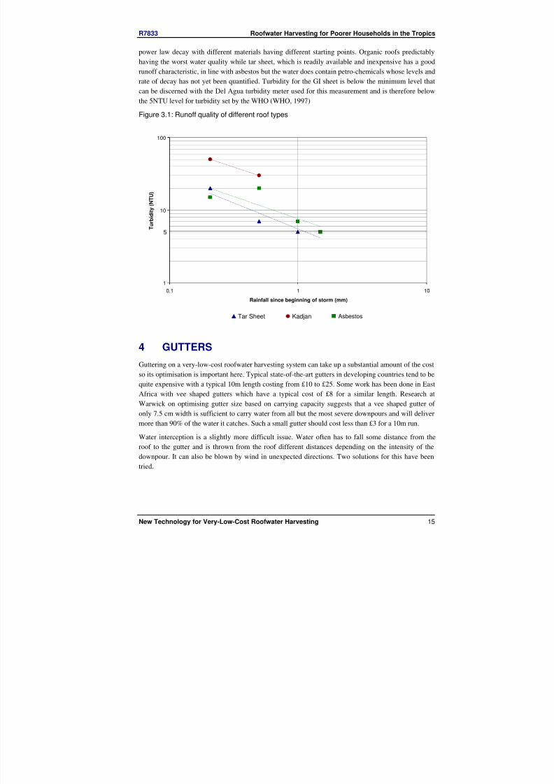
typical set of runoff quality results is shown in Figure 3.1. The characteristic runoff quality follows a
8/3/2019 Roof Water Harvisting 2002
http://slidepdf.com/reader/full/roof-water-harvisting-2002 16/25
R7833 Roofwater Harvesting for Poorer Households in the Tropics
New Technology for Very-Low-Cost Roofwater Harvesting 15
power law decay with different materials having different starting points. Organic roofs predictably
having the worst water quality while tar sheet, which is readily available and inexpensive has a good
runoff characteristic, in line with asbestos but the water does contain petro-chemicals whose levels and
rate of decay has not yet been quantified. Turbidity for the GI sheet is below the minimum level that
can be discerned with the Del Agua turbidity meter used for this measurement and is therefore below
the 5NTU level for turbidity set by the WHO (WHO, 1997)
Figure 3.1: Runoff quality of different roof types
1
10
100
0.1 1 10
Rainfall since beginning of storm (mm)
T u r b i d i t y ( N T U )
Tar Sheet Kadjan Asphestos
4 GUTTERS
Guttering on a very-low-cost roofwater harvesting system can take up a substantial amount of the cost
so its optimisation is important here. Typical state-of-the-art gutters in developing countries tend to be
quite expensive with a typical 10m length costing from £10 to £25. Some work has been done in EastAfrica with vee shaped gutters which have a typical cost of £8 for a similar length. Research at
Warwick on optimising gutter size based on carrying capacity suggests that a vee shaped gutter of
only 7.5 cm width is sufficient to carry water from all but the most severe downpours and will deliver
more than 90% of the water it catches. Such a small gutter should cost less than £3 for a 10m run.
Water interception is a slightly more difficult issue. Water often has to fall some distance from the
roof to the gutter and is thrown from the roof different distances depending on the intensity of the
downpour. It can also be blown by wind in unexpected directions. Two solutions for this have been
tried.
5
Asbestos

8/3/2019 Roof Water Harvisting 2002
http://slidepdf.com/reader/full/roof-water-harvisting-2002 17/25
R7833 Roofwater Harvesting for Poorer Households in the Tropics
New Technology for Very-Low-Cost Roofwater Harvesting 16
Figure 4.1: Gutters configurations
a. G-shaped gutter
Fixing
A
B
b. extended vee
The first (Figure 4.1a) is a complete solution that captures the water at the end of the roof and directs it
into the gutter below. The gutters are also very quick to install as the slope is determined by a variable
manufactured length of vertical support (between A and B) so no adjustment is necessary. Cleaning is
also simple as the inside edge is open for a brush all the way along its length. Problems with the gutter
appear when the length to be guttered is longer than 5m or when thick roofs need to be
accommodated. Under these circumstances the vertical support becomes very long and can flex
causing the gutter to spill. This can be alleviated by using support wires with the loss of some ease of cleaning, however as the vertical support can use a substantial amount of material, the gutter starts to
become expensive at over £9 for 10m.
The second uses the concept of a “upstand”, where one side of the gutter stands proud of the other,
effectively raising the catchment height of the gutter. In the design the usual square gutter has been
simplified to a vee and the upstand is merely an extension of one arm of the vee. This extends the
catchment of the gutter upwards and moves the centre of the catchment out from the roof edge better
matching the profile of water flowing from a roof. The gutter is extremely cheap (less than £3.50 for a
10m run) and can be applied to any sized roof without the need for a facia board. Like all suspended
gutters, the design does need adjustment to maintain the slope and the suffers from guy wires
obstructing cleaning.
5 CONCLUSION
The cost of rainwater harvesting systems can be reduced by a number of methods several of which
have been presented here. The most promising are:
• The use of thin shell cement lining as found in the underground cement tank with an organic roof
and the partially below-ground tank with a ferrocement dome
• The use of free materials and local techniques such as wattle and daub construction and organic
roofs
• Earth technologies such as wattle and daub and rammed earth
• Mass production methods and the use of plastic linings as used in the tube tank and crate tank
• Incorporation of existing structures such as drums
• Smaller profile, sheet-metal gutters which can incorporate features such as water guides or
extended catchment surfaces
Less successful were such techniques as:
• Distributed storage in jerrycans and multiple pots
• Very portable, yet fragile tanks such as the fabric tank

8/3/2019 Roof Water Harvisting 2002
http://slidepdf.com/reader/full/roof-water-harvisting-2002 18/25
R7833 Roofwater Harvesting for Poorer Households in the Tropics
New Technology for Very-Low-Cost Roofwater Harvesting 17
• Over-thin plastering techniques that rely on excessive quality control such as Thin shell cement
slurry lining
Special circumstances can also be incorporated at little cost
• Tall thin structures such as the crate tank and vertically stacked drums can be built for crowded
urban areas
• Auxiliary roofs can be constructed at little cost as an alternative to poor quality organic roof
catchments
But
• Very portable, yet fragile tanks such as the fabric tank
• Roof covering treatments that are built onto an existing roof
Are problematic and cannot be recommended.
6 BIBLIOGRAPHY
Rees, D. (2000) Stabilised Soil Tanks for Rainwater Storage, (Report No. A3). Rainwater Harvesting
Research Group.
Rees, D., & Whitehead, V. (2000) Plastic Tube Tanks : Instructions for Manufacture, (Report No. TR-
RWH08). DTU, UK.
WHO (1997) Guidelines for drinking-water quality. - Vol. 3 : Surveillance and control of community
supplies, World Health Organization Geneva.
8/3/2019 Roof Water Harvisting 2002
http://slidepdf.com/reader/full/roof-water-harvisting-2002 19/25
APPENDIX
Bills of materials and costings

8/3/2019 Roof Water Harvisting 2002
http://slidepdf.com/reader/full/roof-water-harvisting-2002 20/25
unit costs Quantity Used Ethiopia Uganda
MaterialUnitQuantity Ethiopia Uganda Sri Lanka 0.6m3 0.8m3 1.0m3 0.6m3 0.8m3 1.0m3 0.6m3 0.8m3 1.0m3 0.6
Tank
cement bag £2.67 £6.10 £2.69 0.4 0.4 0.4 £1.03 £1.03 £1.03 £2.36 £2.36 £2.36 £
sand m3 £3.57 £3.05 £3.32 0.037 0.037 0.037 £0.13 £0.13 £0.13 £0.11 £0.11 £0.11 £0
aggregate m3 £15.25 £2.98 £11.07 0.061 0.061 0.061 £0.94 £0.94 £0.94 £0.18 £0.18 £0.18 £0
Plastic tube m £0.58 £0.41 £0.37 3.6 4.66 5.7 £2.10 £2.72 £3.33 £1.46 £1.89 £2.32 £
Bracket each £0.70 £0.70 £1.39 1 1 1 £0.70 £0.70 £0.70 £0.70 £0.70 £0.70 £
Basin 20" each £1.33 £0.41 £0.52 1 1 1 £1.33 £1.33 £1.33 £0.41 £0.41 £0.41 £0
Inner Tube 20" each £1.08 £1.08 £0.93 1 1 1 £1.08 £1.08 £1.08 £1.08 £1.08 £1.08 £0
Labour (skilled) day £2.50 £2.03 £2.80 1 1 1 £2.50 £2.50 £2.50 £2.03 £2.03 £2.03 £2
Labour (unskilled) day £0.58 £1.22 £1.87 1 1 1 £0.58 £0.58 £0.58 £1.22 £1.22 £1.22 £
Sub
Pump
1 1/2" pipe m £0.70 £0.83 £0.17 1.9 2.4 2.9 £1.32 £1.67 £2.02 £1.58 £2.00 £2.42 £0
1 1/4" pipe m £0.88 £0.73 £1.74 1.575 2.075 2.575 £1.39 £1.83 £2.28 £1.16 £1.52 £1.89 £2
1 1/2" tee each £1.50 £1.02 £0.50 1 1 1 £1.50 £1.50 £1.50 £1.02 £1.02 £1.02 £0
1/2"pipe m £0.00 £0.00 £0.47 0.2 0.2 0.2 £0.00 £0.00 £0.00 £0.00 £0.00 £0.00 £0
wood (2X2) m £0.00 £0.00 £0.00 0.1 0.1 0.1 £0.00 £0.00 £0.00 £0.00 £0.00 £0.00 £0
wood screw each £0.00 £0.00 £0.01 2 2 2 £0.00 £0.00 £0.00 £0.00 £0.00 £0.00 £0
Labour (skilled) day £2.50 £2.03 £2.80 0.5 0.5 0.5 £1.25 £1.25 £1.25 £1.02 £1.02 £1.02 £
sub £5.47 £6.26 £7.05 £4.77 £5.56 £6.34 £5
Total £5.47 £6.26 £7.05 £4.77 £5.56 £6.34 £5
Total (discounted) £5.47 £6.26 £7.05 £4.77 £5.56 £6.34 £5
Total (ignored) £5.47 £6.26 £7.05 £4.77 £5.56 £6.34 £5

8/3/2019 Roof Water Harvisting 2002
http://slidepdf.com/reader/full/roof-water-harvisting-2002 21/25

8/3/2019 Roof Water Harvisting 2002
http://slidepdf.com/reader/full/roof-water-harvisting-2002 22/25

8/3/2019 Roof Water Harvisting 2002
http://slidepdf.com/reader/full/roof-water-harvisting-2002 23/25
unit costs CostMaterial
UnitQuantity
Ethiopia Uganda Sri Lanka
QuantityUsed
Ethiopia Uganda
8 x 1 planks m £0.46 £0.45 £0.37 32.5 £15.06 £14.54
tap each £0.92 £2.03 £0.70 1.00 £0.92 £2.03
1/2" pipe m £0.25 £1.71 £0.17 0.20 £0.05 £0.34
tap socket m3 £0.21 £0.61 £0.21 2.0 £0.42 £1.22
tap plug (?) each £0.21 £0.61 £0.21 1 £0.21 £0.61
1" GI pipe m £0.25 £1.71 £0.70 0.2 £0.05 £0.34
plastic tube m £0.58 £0.41 £0.37 5 £2.92 £2.03
20" Basin each £1.33 £0.41 £0.52 1 £1.33 £0.41
20" Inner tube each £1.08 £0.61 £0.93 1 £1.08 £0.61
bracket each £0.70 £0.70 £0.70 1 £0.70 £0.70
Labour (skilled) day £2.50 £2.03 £2.80 2 £5.00 £4.07
Labour (unskilled) day £0.58 £1.22 £1.87 0 £0.00 £0.00
Sub $27.75 $26.90
Sub (discounted) $27.75 $26.90
Sum (ignored) $27.75 $26.90

8/3/2019 Roof Water Harvisting 2002
http://slidepdf.com/reader/full/roof-water-harvisting-2002 24/25

8/3/2019 Roof Water Harvisting 2002
http://slidepdf.com/reader/full/roof-water-harvisting-2002 25/25
A collaboration between the DTU and Lanka Rainwater Harvesting Forum, ACORD
Uganda and Water Action Ethiopia.
This document is an output from a project funded by the UK Department for International Development (DFID) for the benefit ofdeveloping countries. The views expressed are not necessarily those of the DFID