roof i body rf a -...
TRANSCRIPT
RF-1
ROOF
I BODY
CONTENTS
C
D
E
F
G
H
J
K
L
M
SECTION RFA
B
RF
Revision: 2004 December 2005 350Z
ROOF
PRECAUTIONS .......................................................... 3Precautions for Supplemental Restraint System (SRS) “AIR BAG” and “SEAT BELT PRE-TEN-SIONER” .................................................................. 3Precautions for Battery Service ................................ 3Precautions .............................................................. 3
PREPARATION ........................................................... 4Special Service Tools ............................................... 4Commercial Service Tools ........................................ 4
SQUEAK AND RATTLE TROUBLE DIAGNOSES ..... 5Work Flow ................................................................ 5
CUSTOMER INTERVIEW ..................................... 5DUPLICATE THE NOISE AND TEST DRIVE ....... 6CHECK RELATED SERVICE BULLETINS ........... 6LOCATE THE NOISE AND IDENTIFY THE ROOT CAUSE ...................................................... 6REPAIR THE CAUSE ........................................... 6CONFIRM THE REPAIR ....................................... 7
Generic Squeak and Rattle Troubleshooting ........... 7INSTRUMENT PANEL .......................................... 7CENTER CONSOLE ............................................. 7DOORS ................................................................. 7TRUNK .................................................................. 8SUNROOF/HEADLINING ..................................... 8SEATS ................................................................... 8UNDERHOOD ....................................................... 8
Diagnostic Worksheet .............................................. 9SOFT TOP .................................................................11
Component Parts and Harness Connector Location ....11System Description ................................................ 12
CONDITIONS FOR OPERATION ....................... 13CONDITIONS FOR STOPPING OPERATION .... 13OUTLINE OF OPERATION ................................. 13OPERATION: FULL CLOSE → FULL OPEN ...... 13OPERATION: FULL OPEN → FULL CLOSE ...... 16
Operation Chart ...................................................... 19CLOSE → OPEN ................................................ 19OPEN → CLOSE ................................................ 21
Indicator Lamp ....................................................... 23Schematic .............................................................. 24
Wiring Diagram ....................................................... 25Terminal and Reference Value of Soft Top Control Unit ......................................................................... 33
CLOSE → OPEN OPERATION ........................... 33OPEN → CLOSE OPERATION ........................... 35
Work Flow ............................................................... 37Trouble Diagnosis Chart by Symptom .................... 37
(CLOSE → OPEN) .............................................. 37(OPEN → CLOSE) .............................................. 38
Soft Top Control Unit Power Supply Check (OP, CL) ... 39Soft Top Switch (OPEN) Check .............................. 39Soft Top Switch (CLOSE) Check ............................ 415th Bow Unlock Actuator Check (Open Operate) ... 435th Bow Half-Latch Switch Check (Open Operate) ... 435th Bow Actuator Check (Open Operate) ............... 455th Bow Full Close Detection Switch Check (Open Operate) ................................................................. 455th Bow Full Open Detection Switch Check (Open Operate) ................................................................. 47Storage Lid Unlock Actuator Check (Open Operate) ... 48Storage Lid Full Close Detection Switch Check (Open Operate) ...................................................... 49Storage Lid Actuator Check (Open Operate) .......... 51Storage Lid Full Open Detection Switch Check (Open Operate) ...................................................... 52Roof Actuator Check (Open Operate) .................... 54Roll Bar Interference Prevention Switch Check (Open Operate) ...................................................... 55Body Interference Prevention Switch Check (Open Operate) ................................................................. 56Roof Full Open Detection Switch Check (Open Operate) ................................................................. 57Storage Lid Unlock Actuator Check (Close Operate) ... 58Storage Lid Full Close Detection Switch Check (Close Operate) ...................................................... 59Storage Lid Actuator Check (Close Operate) ......... 61Storage Lid Full Open Detection Switch Check (Close Operate) ...................................................... 62Body Interference Prevention Switch Check (Close Operate) ................................................................. 64

RF-2Revision: 2004 December 2005 350Z
Roof Actuator Check (Close Operate) .................... 65Roof Full Close Detection Switch Check ................ 665th Bow Actuator Check (Close Operate) .............. 685th Bow Full Close Detection Switch Check (Close Operate) ................................................................. 685th Bow Full Open Detection Switch Check (Close Operate) ................................................................. 705th Bow Half-Latch Switch Check (Close Operate) ... 715th Bow Full-Latch Switch Check ........................... 725th Bow Ending Switch Check ................................ 745th Bow Closure Motor Check ................................ 75Operation Permission Condition Check .................. 76Each Switch Condition Check (Open Operate) ...... 79Each Switch Condition Check (Close Operate) ...... 80Power Window Down Request Signal Check ......... 80Power Window Harness Check .............................. 81Passenger Side Seat Operate Signal Check 1 ....... 81Passenger Side Seat Operate Signal Check 2 ....... 82Passenger Side Seat Operate Signal Check 3 ....... 82Seat Back Position Signal Check ........................... 82Speed Signal Circuit Check .................................... 83Indicator Lamp Circuit Check ................................. 84Removal and Installation of Soft Top Control Unit ... 85
REMOVAL ........................................................... 85INSTALLATION .................................................... 85
Component Parts Drawing ...................................... 86Removal and Installation of Soft Top Assembly ...... 87
REMOVAL ........................................................... 87INSTALLATION .................................................... 88
Removal and Installation of Soft Top Cover ............ 89REMOVAL ........................................................... 89INSTALLATION .................................................... 96
Removal and Installation of Switches ................... 106REMOVAL ......................................................... 106INSTALLATION .................................................. 106
Removal and Installation of Roof Actuator ........... 107REMOVAL ......................................................... 107INSTALLATION .................................................. 107
Removal and Installation of 5th Bow Drive Unit .... 107
REMOVAL ..........................................................107INSTALLATION .................................................. 110
Removal and Installation of Front Lock ................. 114REMOVAL .......................................................... 114INSTALLATION .................................................. 114INSPECTION AND ADJUSTMENT ................... 114
Repairing Method for Water Leakage Around Doors .115WATER LEAKAGE FROM A .............................. 115WATER LEAKAGE FROM B .............................. 116WATER LEAKAGE FROM C ............................. 116WATER LEAKAGE FROM D ............................. 117WATER LEAKAGE FROM E .............................. 117WATER LEAKAGE TEST .................................. 118
Correspondence in Emergency ............................ 119MANUAL OPERATION (SOFT TOP FULLY OPEN � FULLY CLOSE) .................................. 119MANUAL OPERATION (SOFT TOP FULLY CLOSE � FULLY OPEN) ..................................120
STORAGE LID .........................................................122Removal and Installation of Storage Lid Assembly .122
REMOVAL ..........................................................122INSTALLATION ..................................................122
Removal and Installation of Storage Lid Inside Unit .123REMOVAL ..........................................................123INSTALLATION ..................................................124
Removal and Installation of Storage Lid Actuator .125REMOVAL ..........................................................125INSTALLATION ..................................................125
Removal and Installation of Storage Room Finisher .125REMOVAL ..........................................................125INSTALLATION ..................................................126
Removal and Installation of Storage Outer Protector .126Adjustment of Storage Lid .....................................127
ADJUSTMENT IN FULLY CLOSED POSITION .127ADJUSTMENT IN FULLY OPENED POSITION .128
Removal and Installation of Storage Lid Striker Lock & Storage Lid Emergency Opener Cable ..............129
REMOVAL ..........................................................129INSTALLATION ..................................................129
PRECAUTIONS
RF-3
C
D
E
F
G
H
J
K
L
M
A
B
RF
Revision: 2004 December 2005 350Z
PRECAUTIONS PFP:00001
Precautions for Supplemental Restraint System (SRS) “AIR BAG” and “SEAT BELT PRE-TENSIONER” AIS003Y9
The Supplemental Restraint System such as “AIR BAG” and “SEAT BELT PRE-TENSIONER”, used alongwith a front seat belt, helps to reduce the risk or severity of injury to the driver and front passenger for certaintypes of collision. This system includes seat belt switch inputs and dual stage front air bag modules. The SRSsystem uses the seat belt switches to determine the front air bag deployment, and may only deploy one frontair bag, depending on the severity of a collision and whether the front occupants are belted or unbelted.Information necessary to service the system safely is included in the SRS and SB section of this Service Man-ual.WARNING:● To avoid rendering the SRS inoperative, which could increase the risk of personal injury or death
in the event of a collision which would result in air bag inflation, all maintenance must be per-formed by an authorized NISSAN/INFINITI dealer.
● Improper maintenance, including incorrect removal and installation of the SRS, can lead to per-sonal injury caused by unintentional activation of the system. For removal of Spiral Cable and AirBag Module, see the SRS section.
● Do not use electrical test equipment on any circuit related to the SRS unless instructed to in thisService Manual. SRS wiring harnesses can be identified by yellow and/or orange harnesses orharness connectors.
Precautions for Battery Service AIS003YA
Before disconnecting the battery, lower both the driver and passenger windows. This will prevent any interfer-ence between the window edge and the vehicle when the door is opened/closed. During normal operation, thewindow slightly raises and lowers automatically to prevent any window to vehicle interference. The automaticwindow function will not work with the battery disconnected.
Precautions AIS003YB
● Disconnect both battery cables in advance.● Never tamper with or force air bag lid open, as this may adversely affect air bag performance.● Be careful not to scratch pad and other parts.● When removing or disassembling any part, be careful not to damage or deform it. Protect parts, which
may get in the way with cloth.● When removing parts with a screwdriver or other tool, protect parts by wrapping them with vinyl or tape. ● Keep removed parts protected with cloth.● If a clip is deformed or damaged, replace it.● If an unreusable part is removed, replace it with a new one.● Tighten bolts and nuts firmly to the specified torque.● After re-assembly has been completed, make sure each part functions correctly.● Remove stains in the following way.Water-soluble stains:Dip a soft cloth in warm water, and then squeeze it tightly. After wiping the stain, wipe with a soft dry cloth.Oil stain:Dissolve a synthetic detergent in warm water (density of 2 to 3% or less), dip the cloth, then clean off the stainwith the cloth. Next, dip the cloth in fresh water and squeeze it tightly. Then clean off the detergent completely.Then wipe the area with a soft dry cloth.● Do not use any organic solvent, such as thinner or benzine.
RF-4
PREPARATION
Revision: 2004 December 2005 350Z
PREPARATION PFP:00002
Special Service Tools AIS003YC
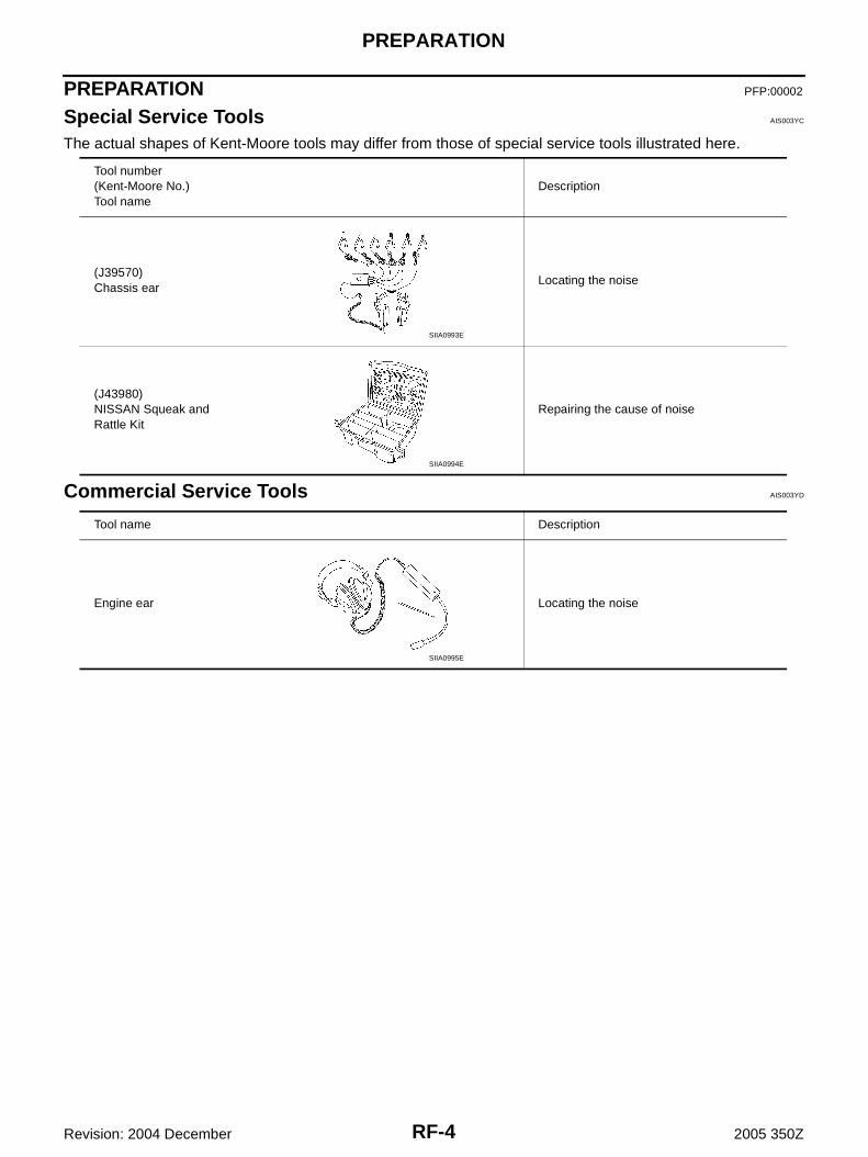
The actual shapes of Kent-Moore tools may differ from those of special service tools illustrated here.
Commercial Service Tools AIS003YD
Tool number(Kent-Moore No.)Tool name
Description
(J39570)Chassis ear
Locating the noise
(J43980)NISSAN Squeak and Rattle Kit
Repairing the cause of noise
SIIA0993E
SIIA0994E
Tool name Description
Engine ear Locating the noise
SIIA0995E
SQUEAK AND RATTLE TROUBLE DIAGNOSES
RF-5
C
D
E
F
G
H
J
K
L
M
A
B
RF
Revision: 2004 December 2005 350Z
SQUEAK AND RATTLE TROUBLE DIAGNOSES PFP:00000
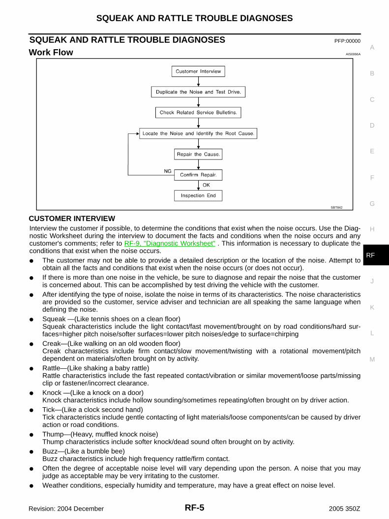
Work Flow AIS0066A
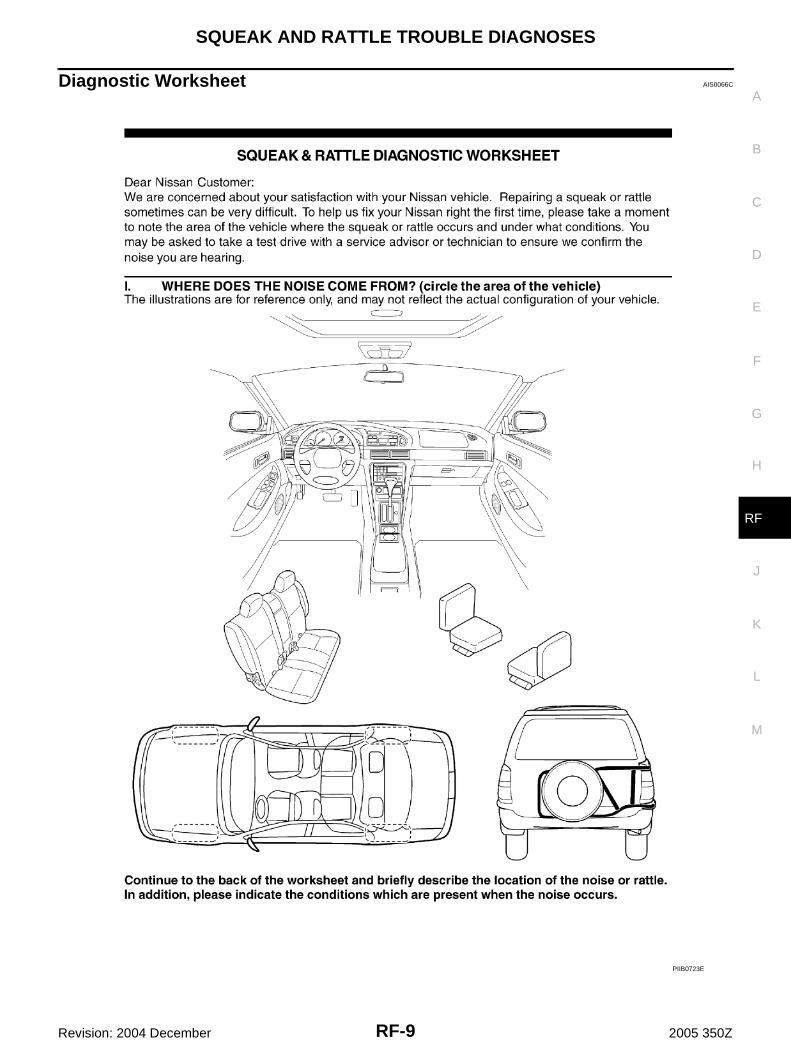
CUSTOMER INTERVIEWInterview the customer if possible, to determine the conditions that exist when the noise occurs. Use the Diag-nostic Worksheet during the interview to document the facts and conditions when the noise occurs and anycustomer's comments; refer to RF-9, "Diagnostic Worksheet" . This information is necessary to duplicate theconditions that exist when the noise occurs.● The customer may not be able to provide a detailed description or the location of the noise. Attempt to
obtain all the facts and conditions that exist when the noise occurs (or does not occur).● If there is more than one noise in the vehicle, be sure to diagnose and repair the noise that the customer
is concerned about. This can be accomplished by test driving the vehicle with the customer.● After identifying the type of noise, isolate the noise in terms of its characteristics. The noise characteristics
are provided so the customer, service adviser and technician are all speaking the same language whendefining the noise.
● Squeak —(Like tennis shoes on a clean floor)Squeak characteristics include the light contact/fast movement/brought on by road conditions/hard sur-faces=higher pitch noise/softer surfaces=lower pitch noises/edge to surface=chirping
● Creak—(Like walking on an old wooden floor)Creak characteristics include firm contact/slow movement/twisting with a rotational movement/pitchdependent on materials/often brought on by activity.
● Rattle—(Like shaking a baby rattle)Rattle characteristics include the fast repeated contact/vibration or similar movement/loose parts/missingclip or fastener/incorrect clearance.
● Knock —(Like a knock on a door)Knock characteristics include hollow sounding/sometimes repeating/often brought on by driver action.
● Tick—(Like a clock second hand)Tick characteristics include gentle contacting of light materials/loose components/can be caused by driveraction or road conditions.
● Thump—(Heavy, muffled knock noise)Thump characteristics include softer knock/dead sound often brought on by activity.
● Buzz—(Like a bumble bee)Buzz characteristics include high frequency rattle/firm contact.
● Often the degree of acceptable noise level will vary depending upon the person. A noise that you mayjudge as acceptable may be very irritating to the customer.
● Weather conditions, especially humidity and temperature, may have a great effect on noise level.
SBT842
RF-6
SQUEAK AND RATTLE TROUBLE DIAGNOSES
Revision: 2004 December 2005 350Z
DUPLICATE THE NOISE AND TEST DRIVEIf possible, drive the vehicle with the customer until the noise is duplicated. Note any additional information onthe Diagnostic Worksheet regarding the conditions or location of the noise. This information can be used toduplicate the same conditions when you confirm the repair.If the noise can be duplicated easily during the test drive, to help identify the source of the noise, try to dupli-cate the noise with the vehicle stopped by doing one or all of the following:1) Close a door.2) Tap or push/pull around the area where the noise appears to be coming from.3) Rev the engine.4) Use a floor jack to recreate vehicle “twist”.5) At idle, apply engine load (electrical load, half-clutch on M/T models, drive position on A/T models).6) Raise the vehicle on a hoist and hit a tire with a rubber hammer.● Drive the vehicle and attempt to duplicate the conditions the customer states exist when the noise occurs.● If it is difficult to duplicate the noise, drive the vehicle slowly on an undulating or rough road to stress the
vehicle body.
CHECK RELATED SERVICE BULLETINSAfter verifying the customer concern or symptom, check ASIST for Technical Service Bulletins (TSBs) relatedto that concern or symptom.If a TSB relates to the symptom, follow the procedure to repair the noise.
LOCATE THE NOISE AND IDENTIFY THE ROOT CAUSE1. Narrow down the noise to a general area. To help pinpoint the source of the noise, use a listening tool
(Chassis Ear: J-39570, Engine Ear and mechanics stethoscope).2. Narrow down the noise to a more specific area and identify the cause of the noise by:● removing the components in the area that you suspect the noise is coming from.
Do not use too much force when removing clips and fasteners, otherwise clips and fastener can be brokenor lost during the repair, resulting in the creation of new noise.
● tapping or pushing/pulling the component that you suspect is causing the noise.Do not tap or push/pull the component with excessive force, otherwise the noise will be eliminated onlytemporarily.
● feeling for a vibration with your hand by touching the component(s) that you suspect is (are) causing thenoise.
● placing a piece of paper between components that you suspect are causing the noise.● looking for loose components and contact marks.
Refer to RF-7, "Generic Squeak and Rattle Troubleshooting" .
REPAIR THE CAUSE● If the cause is a loose component, tighten the component securely.● If the cause is insufficient clearance between components:– separate components by repositioning or loosening and retightening the component, if possible.– insulate components with a suitable insulator such as urethane pads, foam blocks, felt cloth tape or ure-
thane tape. A Nissan Squeak and Rattle Kit (J-43980) is available through your authorized Nissan PartsDepartment.
CAUTION:Do not use excessive force as many components are constructed of plastic and may be damaged.NOTE:Always check with the Parts Department for the latest parts information.The following materials are contained in the Nissan Squeak and Rattle Kit (J-43980). Each item can beordered separately as needed.URETHANE PADS [1.5 mm (0.059 in) thick]Insulates connectors, harness, etc.76268-9E005: 100 × 135 mm (3.94 × 5.31 in)/76884-71L01: 60 × 85 mm (2.36 × 3.35 in)/76884-71L02: 15 × 25 mm (0.59 × 0.98 in)INSULATOR (Foam blocks)Insulates components from contact. Can be used to fill space behind a panel.73982-9E000: 45 mm (1.77 in) thick, 50 × 50 mm (1.97 × 1.97 in)/73982-50Y00:10 mm (0.39 in) thick, 50 × 50 mm (1.97 × 1.97 in)
SQUEAK AND RATTLE TROUBLE DIAGNOSES
RF-7
C
D
E
F
G
H
J
K
L
M
A
B
RF
Revision: 2004 December 2005 350Z
INSULATOR (Light foam block)80845-71L00: 30 mm (1.18 in) thick, 30 × 50 mm (1.18 × 1.97 in)FELT CLOTHTAPEUsed to insulate where movement does not occur. Ideal for instrument panel applications.68370-4B000: 15 × 25 mm (0.59 × 0.98 in) pad/68239-13E00: 5 mm (0.20 in) wide tape rollThe following materials, not found in the kit, can also be used to repair squeaks and rattles.UHMW (TEFLON) TAPEInsulates where slight movement is present. Ideal for instrument panel applications.SILICONE GREASEUsed in place of UHMW tape that will be visible or not fit. Will only last a few months.SILICONE SPRAYUse when grease cannot be applied.DUCT TAPEUse to eliminate movement.
CONFIRM THE REPAIRConfirm that the cause of a noise is repaired by test driving the vehicle. Operate the vehicle under the sameconditions as when the noise originally occurred. Refer to the notes on the Diagnostic Worksheet.
Generic Squeak and Rattle Troubleshooting AIS0066B
Refer to Table of Contents for specific component removal and installation information.
INSTRUMENT PANELMost incidents are caused by contact and movement between:1. The cluster lid A and instrument panel2. Acrylic lens and combination meter housing3. Instrument panel to front pillar garnish4. Instrument panel to windshield5. Instrument panel mounting pins6. Wiring harnesses behind the combination meter7. A/C defroster duct and duct jointThese incidents can usually be located by tapping or moving the components to duplicate the noise or bypressing on the components while driving to stop the noise. Most of these incidents can be repaired by apply-ing felt cloth tape or silicon spray (in hard to reach areas). Urethane pads can be used to insulate wiring har-ness.CAUTION:Do not use silicone spray to isolate a squeak or rattle. If you saturate the area with silicone, you willnot be able to recheck the repair.
CENTER CONSOLEComponents to pay attention to include:1. Shifter assembly cover to finisher2. A/C control unit and cluster lid C3. Wiring harnesses behind audio and A/C control unitThe instrument panel repair and isolation procedures also apply to the center console.
DOORSPay attention to the:1. Finisher and inner panel making a slapping noise2. Inside handle escutcheon to door finisher3. Wiring harnesses tapping4. Door striker out of alignment causing a popping noise on starts and stopsTapping or moving the components or pressing on them while driving to duplicate the conditions can isolatemany of these incidents. You can usually insulate the areas with felt cloth tape or insulator foam blocks fromthe Nissan Squeak and Rattle Kit (J-43980) to repair the noise.
RF-8
SQUEAK AND RATTLE TROUBLE DIAGNOSES
Revision: 2004 December 2005 350Z
TRUNKTrunk noises are often caused by a loose jack or loose items put into the trunk by the owner.In addition look for:1. Trunk lid dumpers out of adjustment2. Trunk lid striker out of adjustment3. The trunk lid torsion bars knocking together4. A loose license plate or bracketMost of these incidents can be repaired by adjusting, securing or insulating the item(s) or component(s) caus-ing the noise.
SUNROOF/HEADLININGNoises in the sunroof/headlining area can often be traced to one of the following:1. Sunroof lid, rail, linkage or seals making a rattle or light knocking noise2. Sunvisor shaft shaking in the holder3. Front or rear windshield touching headlining and squeakingAgain, pressing on the components to stop the noise while duplicating the conditions can isolate most of theseincidents. Repairs usually consist of insulating with felt cloth tape.
SEATSWhen isolating seat noise it's important to note the position the seat is in and the load placed on the seat whenthe noise is present. These conditions should be duplicated when verifying and isolating the cause of thenoise.Cause of seat noise include:1. Headrest rods and holder2. A squeak between the seat pad cushion and frame3. The rear seatback lock and bracketThese noises can be isolated by moving or pressing on the suspected components while duplicating the con-ditions under which the noise occurs. Most of these incidents can be repaired by repositioning the componentor applying urethane tape to the contact area.
UNDERHOODSome interior noise may be caused by components under the hood or on the engine wall. The noise is thentransmitted into the passenger compartment.Causes of transmitted underhood noise include:1. Any component mounted to the engine wall2. Components that pass through the engine wall3. Engine wall mounts and connectors4. Loose radiator mounting pins5. Hood bumpers out of adjustment6. Hood striker out of adjustmentThese noises can be difficult to isolate since they cannot be reached from the interior of the vehicle. The bestmethod is to secure, move or insulate one component at a time and test drive the vehicle. Also, engine RPMor load can be changed to isolate the noise. Repairs can usually be made by moving, adjusting, securing, orinsulating the component causing the noise.
SQUEAK AND RATTLE TROUBLE DIAGNOSES
RF-9
C
D
E
F
G
H
J
K
L
M
A
B
RF
Revision: 2004 December 2005 350Z
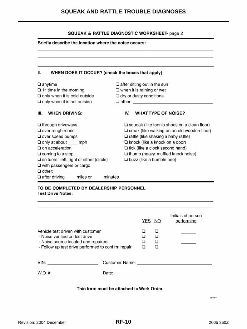
Diagnostic Worksheet AIS0066C
PIIB0723E
RF-10
SQUEAK AND RATTLE TROUBLE DIAGNOSES
Revision: 2004 December 2005 350Z
SBT844
SOFT TOP
RF-11
C
D
E
F
G
H
J
K
L
M
A
B
RF
Revision: 2004 December 2005 350Z
SOFT TOP PFP:97002
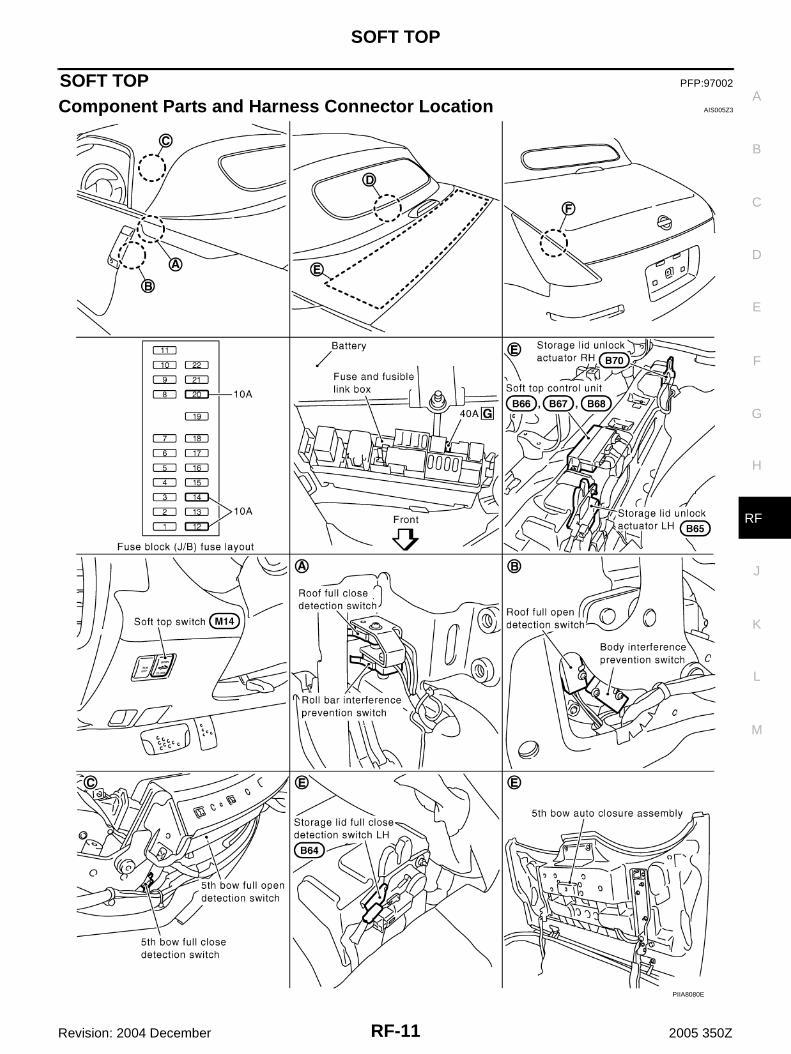
Component Parts and Harness Connector Location AIS005Z3
PIIA8080E

RF-12
SOFT TOP
Revision: 2004 December 2005 350Z
Following Parts Are Built Into 5th Bow Auto Closure Assembly.● 5th bow half-latch switch built in 5th bow lock assembly in storage lid.● 5th bow full-latch switch built in 5th bow lock assembly in storage lid.● 5th bow ending switch built in 5th bow lock assembly in storage lid.● 5th bow unlock actuator.● 5th bow closure motor.NOTE:Always replace following switches as a 5th bow lock assembly.● 5th bow half-latch switch● 5th bow full-latch switch● 5th bow ending switch.5th bow full open detection switch and 5th bow full close detection switch are built into 5th bow switch assem-bly located at plate rail RR. Replace above switches as a plate rail RR.
System Description AIS005Z4
An electronic soft top open/close system has been adopted that allows the soft top to be opened or closedusing the soft top switch.The following parts operate, linked with the operation of the soft top.● When the soft top begins to operate, the passenger seat tilts forward. When operation is completed, it
returns to its original position.(It does not move when the seat cancel switch is ON.)
● When the soft top begins to operate, both power windows activate to the fully-open position.(They do not activate to the fully-closed position after operation is completed.)Moreover, power window cannot be operated while soft top is operating.
When the soft top switch is released, soft top operation stops.
PIIA8081E
SOFT TOP
RF-13
C
D
E
F
G
H
J
K
L
M
A
B
RF
Revision: 2004 December 2005 350Z
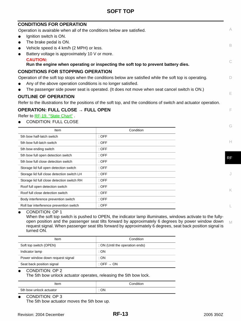
CONDITIONS FOR OPERATIONOperation is avairable when all of the conditions below are satisfied.● Ignition switch is ON.● The brake pedal is ON.● Vehicle speed is 4 km/h (2 MPH) or less.● Battery voltage is approximately 10 V or more.
CAUTION:Run the engine when operating or inspecting the soft top to prevent battery dies.
CONDITIONS FOR STOPPING OPERATIONOperation of the soft top stops when the conditions below are satisfied while the soft top is operating.● Any of the above operation conditions is no longer satisfied.● The passenger side power seat is operated. (It does not move when seat cancel switch is ON.)
OUTLINE OF OPERATIONRefer to the illustrations for the positions of the soft top, and the conditions of switch and actuator operation.
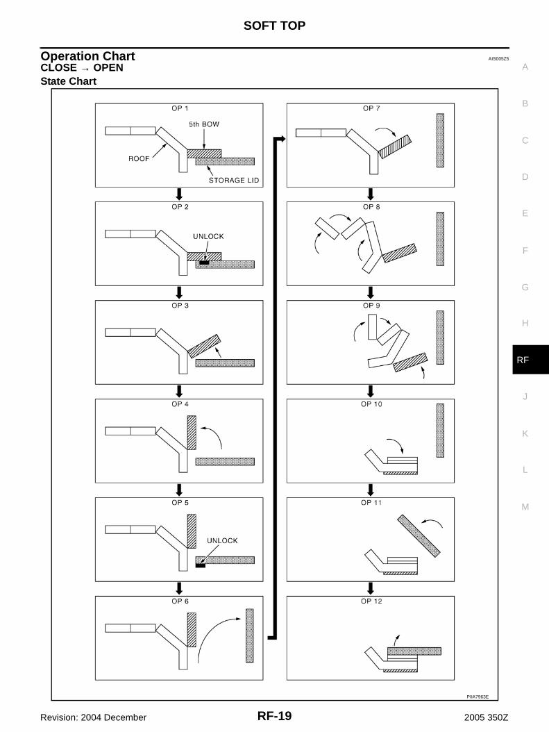
OPERATION: FULL CLOSE → FULL OPENRefer to RF-19, "State Chart" .● CONDITION: FULL CLOSE
● CONDITION: OP 1When the soft top switch is pushed to OPEN, the indicator lamp illuminates, windows activate to the fully-open position and the passenger seat tilts forward by approximately 6 degrees by power window downrequest signal. When passenger seat tilts forward by approximately 6 degrees, seat back position signal isturned ON.
● CONDITION: OP 2The 5th bow unlock actuator operates, releasing the 5th bow lock.
● CONDITION: OP 3The 5th bow actuator moves the 5th bow up.
Item Condition
5th bow half-latch switch : OFF
5th bow full-latch switch : OFF
5th bow ending switch : OFF
5th bow full open detection switch : OFF
5th bow full close detection switch : OFF
Storage lid full open detection switch : OFF
Storage lid full close detection switch LH : OFF
Storage lid full close detection switch RH : OFF
Roof full open detection switch : OFF
Roof full close detection switch : OFF
Body interference prevention switch : OFF
Roll bar interference prevention switch : OFF
Item Condition
Soft top switch (OPEN) : ON (Until the operation ends)
Indicator lamp : ON
Power window down request signal : ON
Seat back position signal : OFF → ON
Item Condition
5th bow unlock actuator : ON
RF-14
SOFT TOP
Revision: 2004 December 2005 350Z
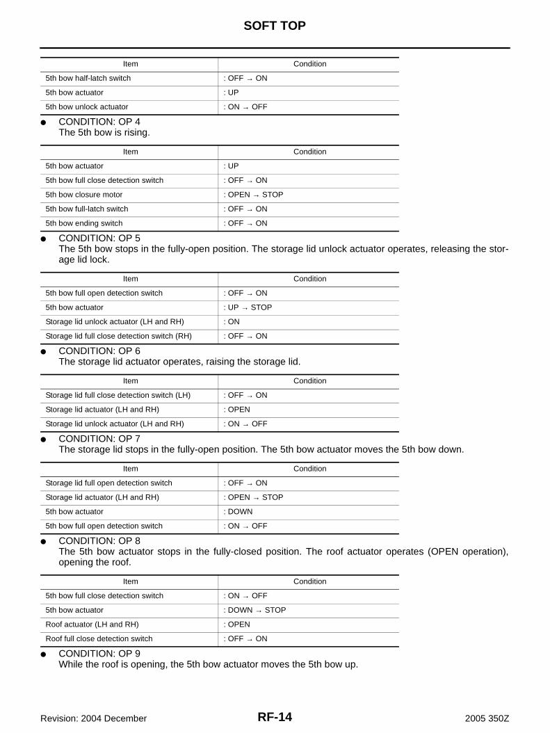
● CONDITION: OP 4The 5th bow is rising.
● CONDITION: OP 5The 5th bow stops in the fully-open position. The storage lid unlock actuator operates, releasing the stor-age lid lock.
● CONDITION: OP 6The storage lid actuator operates, raising the storage lid.
● CONDITION: OP 7The storage lid stops in the fully-open position. The 5th bow actuator moves the 5th bow down.
● CONDITION: OP 8The 5th bow actuator stops in the fully-closed position. The roof actuator operates (OPEN operation),opening the roof.
● CONDITION: OP 9While the roof is opening, the 5th bow actuator moves the 5th bow up.
Item Condition
5th bow half-latch switch : OFF → ON
5th bow actuator : UP
5th bow unlock actuator : ON → OFF
Item Condition
5th bow actuator : UP
5th bow full close detection switch : OFF → ON
5th bow closure motor : OPEN → STOP
5th bow full-latch switch : OFF → ON
5th bow ending switch : OFF → ON
Item Condition
5th bow full open detection switch : OFF → ON
5th bow actuator : UP → STOP
Storage lid unlock actuator (LH and RH) : ON
Storage lid full close detection switch (RH) : OFF → ON
Item Condition
Storage lid full close detection switch (LH) : OFF → ON
Storage lid actuator (LH and RH) : OPEN
Storage lid unlock actuator (LH and RH) : ON → OFF
Item Condition
Storage lid full open detection switch : OFF → ON
Storage lid actuator (LH and RH) : OPEN → STOP
5th bow actuator : DOWN
5th bow full open detection switch : ON → OFF
Item Condition
5th bow full close detection switch : ON → OFF
5th bow actuator : DOWN → STOP
Roof actuator (LH and RH) : OPEN
Roof full close detection switch : OFF → ON

SOFT TOP
RF-15
C
D
E
F
G
H
J
K
L
M
A
B
RF
Revision: 2004 December 2005 350Z
● CONDITION: OP 10While the roof is opening, the 5th bow stops in the fully-open position.
● CONDITION: OP 11The roof is stored and stops motion. The storage lid actuator operates (DOWN operation) to lower thestorage lid.The passenger seat also returns to its original position.
● CONDITION: OP 12At the fully-closed position, the storage lid inverts and stops. The passenger seat tilts back. Opening oper-ation is completed, and the indicator lamp turns OFF.
Item Condition
Roof actuator (LH and RH) : OPEN
5th bow actuator : UP
5th bow full close detection switch : OFF → ON
Roll bar interference prevention switch : OFF → ON
Item Condition
Roof actuator (LH and RH) : OPEN
5th bow full open detection switch : OFF → ON
5th bow actuator : UP → STOP
Body interference prevention switch : OFF → ON
Item Condition
Roof full open detection switch : OFF → ON
Roof actuator (LH and RH) : OPEN → STOP
Storage lid actuator (LH and RH) : CLOSE
Storage lid full open detection switch : ON → OFF
Storage lid full close detection switch (LH) : ON → OFF
Item Condition
Storage lid full close detection switch (RH) : ON → OFF
Storage lid actuator (LH and RH) : CLOSE → OPEN → STOP
Indicator lamp : ON → OFF
RF-16
SOFT TOP
Revision: 2004 December 2005 350Z
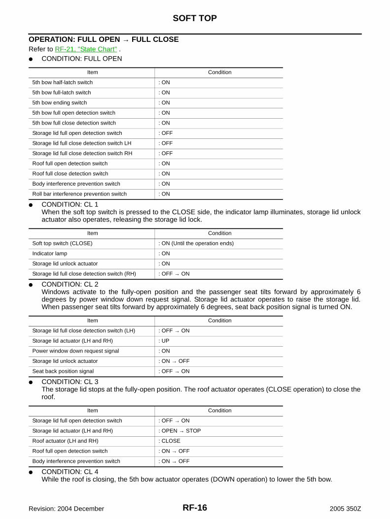
OPERATION: FULL OPEN → FULL CLOSERefer to RF-21, "State Chart" .● CONDITION: FULL OPEN
● CONDITION: CL 1When the soft top switch is pressed to the CLOSE side, the indicator lamp illuminates, storage lid unlockactuator also operates, releasing the storage lid lock.
● CONDITION: CL 2Windows activate to the fully-open position and the passenger seat tilts forward by approximately 6degrees by power window down request signal. Storage lid actuator operates to raise the storage lid.When passenger seat tilts forward by approximately 6 degrees, seat back position signal is turned ON.
● CONDITION: CL 3The storage lid stops at the fully-open position. The roof actuator operates (CLOSE operation) to close theroof.
● CONDITION: CL 4While the roof is closing, the 5th bow actuator operates (DOWN operation) to lower the 5th bow.
Item Condition
5th bow half-latch switch : ON
5th bow full-latch switch : ON
5th bow ending switch : ON
5th bow full open detection switch : ON
5th bow full close detection switch : ON
Storage lid full open detection switch : OFF
Storage lid full close detection switch LH : OFF
Storage lid full close detection switch RH : OFF
Roof full open detection switch : ON
Roof full close detection switch : ON
Body interference prevention switch : ON
Roll bar interference prevention switch : ON
Item Condition
Soft top switch (CLOSE) : ON (Until the operation ends)
Indicator lamp : ON
Storage lid unlock actuator : ON
Storage lid full close detection switch (RH) : OFF → ON
Item Condition
Storage lid full close detection switch (LH) : OFF → ON
Storage lid actuator (LH and RH) : UP
Power window down request signal : ON
Storage lid unlock actuator : ON → OFF
Seat back position signal : OFF → ON
Item Condition
Storage lid full open detection switch : OFF → ON
Storage lid actuator (LH and RH) : OPEN → STOP
Roof actuator (LH and RH) : CLOSE
Roof full open detection switch : ON → OFF
Body interference prevention switch : ON → OFF

SOFT TOP
RF-17
C
D
E
F
G
H
J
K
L
M
A
B
RF
Revision: 2004 December 2005 350Z
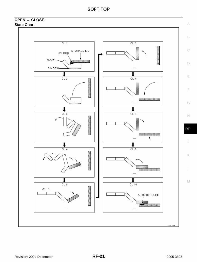
● CONDITOIN: CL 5The roof is closing, and 5th bow is lowering.
● CONDITION: CL 6The roof stops at the fully-closed position. The 5th bow actuator inverts, raising the 5th bow.
● CONDITON: CL 7The 5th bow stops in the fully-open position. The storage lid actuator operates (DOWN operation) lowerthe storage lid.
● CONDITION: CL 8The storage lid inverts and stops at the fully-closed position. The 5th bow actuator operates (DOWN oper-ation) to lower the 5th bow.
● CONDITION: CL 9The 5th bow is lowering.
● CONDITION: CL 105th bow auto closure operates. The passenger seat tilts back. Closing operation is completed, and theindicator lamp turns OFF. The passenger seat also returns to its original position.
Item Condition
Roof actuator (LH and RH) : CLOSE
5th bow actuator : DOWN
5th bow full open detection switch : ON → OFF
Item Condition
Roof actuator (LH and RH) : CLOSE
5th bow full close detection switch : ON → OFF
5th bow actuator : DOWN → STOP
Roll bar interference prevention switch : ON → OFF
Item Condition
Roof full close detection switch : ON → OFF
Roof actuator (LH and RH) : CLOSE → STOP
5th bow actuator : UP
5th bow full close detection switch : OFF → ON
Item Condition
5th bow full open detection switch : OFF → ON
5th bow actuator : UP → STOP
Storage lid actuator (LH and RH) : CLOSE
Storage lid full open detection switch : ON → OFF
Storage lid full close detection switch (LH) : ON → OFF
Item Condition
Storage lid full close detection switch (RH) : ON → OFF
Storage lid actuator : CLOSE → OPEN → STOP
5th bow actuator : DOWN
5th bow full open detection switch : ON → OFF
Item Condition
5th bow actuator : DOWN
5th bow full close detection switch : ON → OFF

RF-18
SOFT TOP
Revision: 2004 December 2005 350Z
Item Condition
5th bow actuator : DOWN → STOP
5th bow half-latch switch : ON → OFF
5th bow full-latch switch : ON → OFF
5th bow ending switch : ON → OFF
5th bow closure motor : CLOSE → STOP
Indicator lamp : ON → OFF
SOFT TOP
RF-19
C
D
E
F
G
H
J
K
L
M
A
B
RF
Revision: 2004 December 2005 350Z
Operation Chart AIS005Z5
CLOSE → OPENState Chart
PIIA7963E
RF-20
SOFT TOP
Revision: 2004 December 2005 350Z
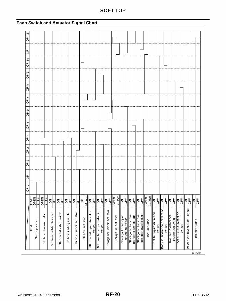
Each Switch and Actuator Signal Chart
PIIA7965E
SOFT TOP
RF-21
C
D
E
F
G
H
J
K
L
M
A
B
RF
Revision: 2004 December 2005 350Z
OPEN → CLOSEState Chart
PIIA7964E
RF-22
SOFT TOP
Revision: 2004 December 2005 350Z
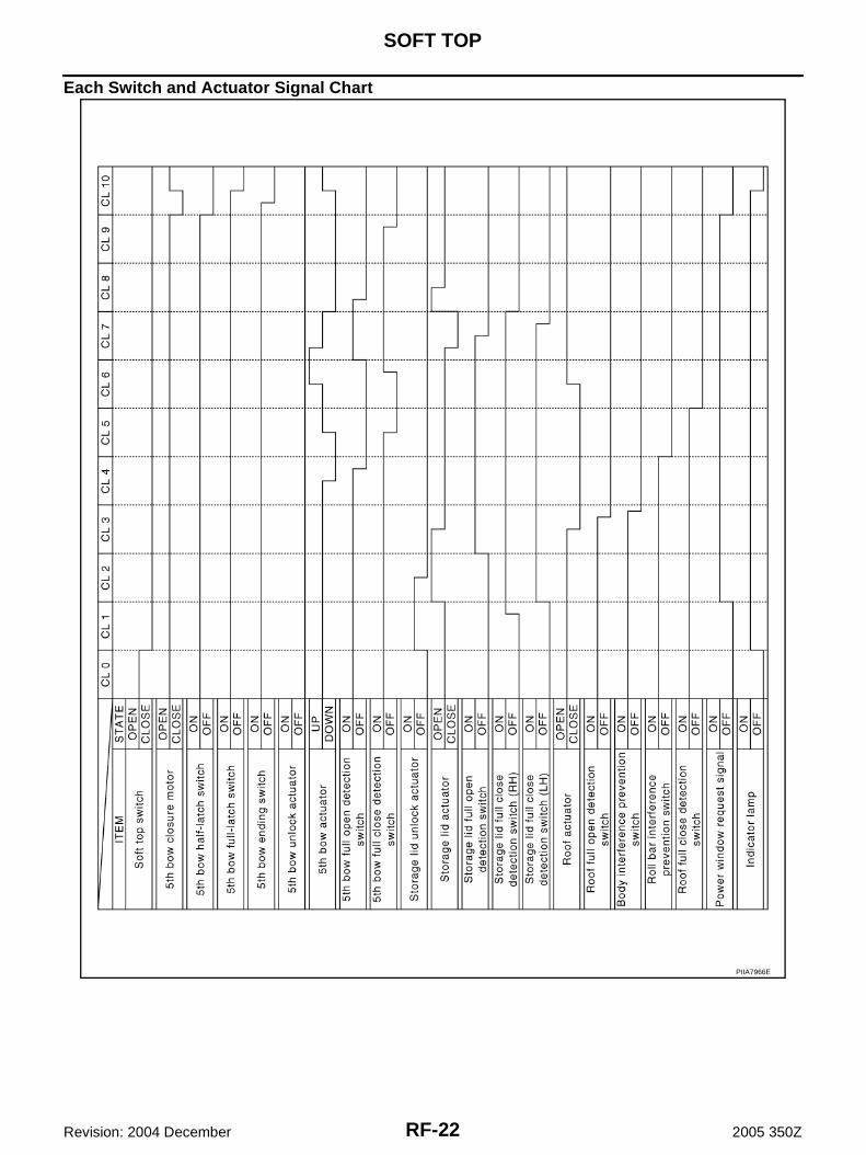
Each Switch and Actuator Signal Chart
PIIA7966E
SOFT TOP
RF-23
C
D
E
F
G
H
J
K
L
M
A
B
RF
Revision: 2004 December 2005 350Z
Indicator Lamp AIS005Z6
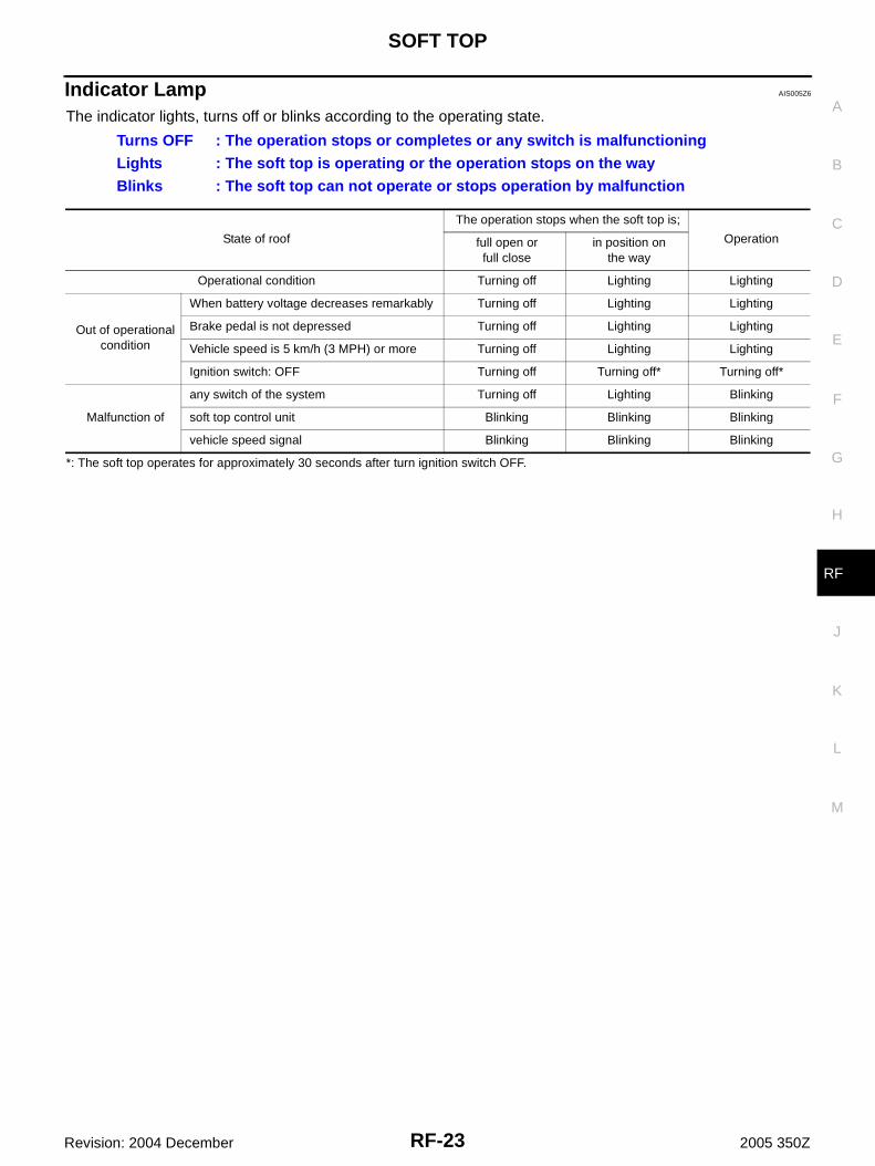
The indicator lights, turns off or blinks according to the operating state.
*: The soft top operates for approximately 30 seconds after turn ignition switch OFF.
Turns OFF : The operation stops or completes or any switch is malfunctioningLights : The soft top is operating or the operation stops on the wayBlinks : The soft top can not operate or stops operation by malfunction
State of roof
The operation stops when the soft top is;
Operationfull open orfull close
in position onthe way
Operational condition Turning off Lighting Lighting
Out of operationalcondition
When battery voltage decreases remarkably Turning off Lighting Lighting
Brake pedal is not depressed Turning off Lighting Lighting
Vehicle speed is 5 km/h (3 MPH) or more Turning off Lighting Lighting
Ignition switch: OFF Turning off Turning off* Turning off*
Malfunction of
any switch of the system Turning off Lighting Blinking
soft top control unit Blinking Blinking Blinking
vehicle speed signal Blinking Blinking Blinking
RF-24
SOFT TOP
Revision: 2004 December 2005 350Z
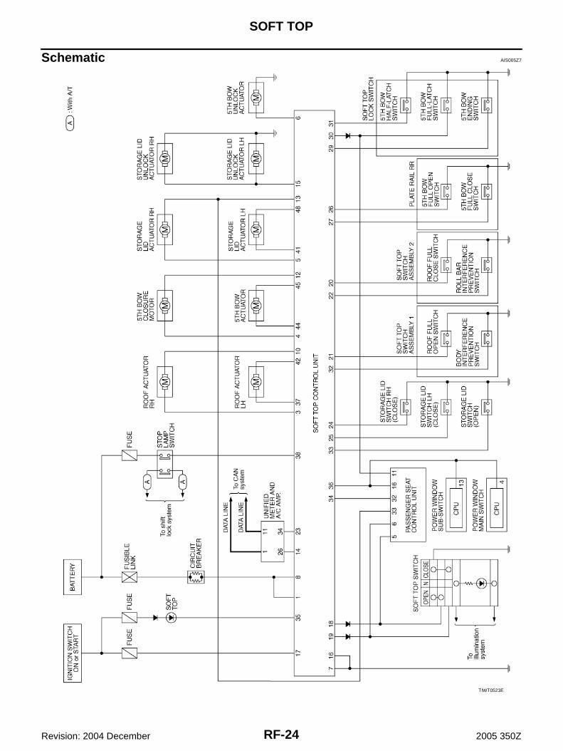
Schematic AIS005Z7
TIWT0523E

SOFT TOP
RF-25
C
D
E
F
G
H
J
K
L
M
A
B
RF
Revision: 2004 December 2005 350Z
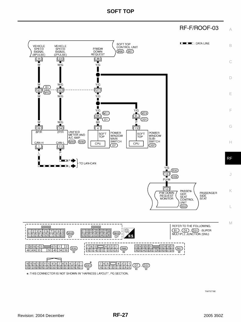
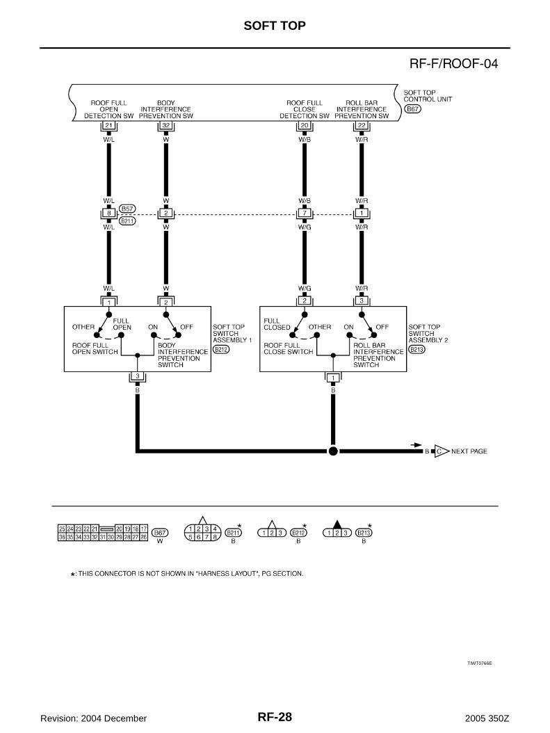
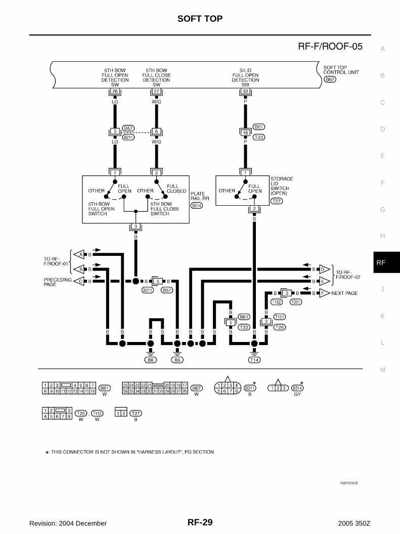
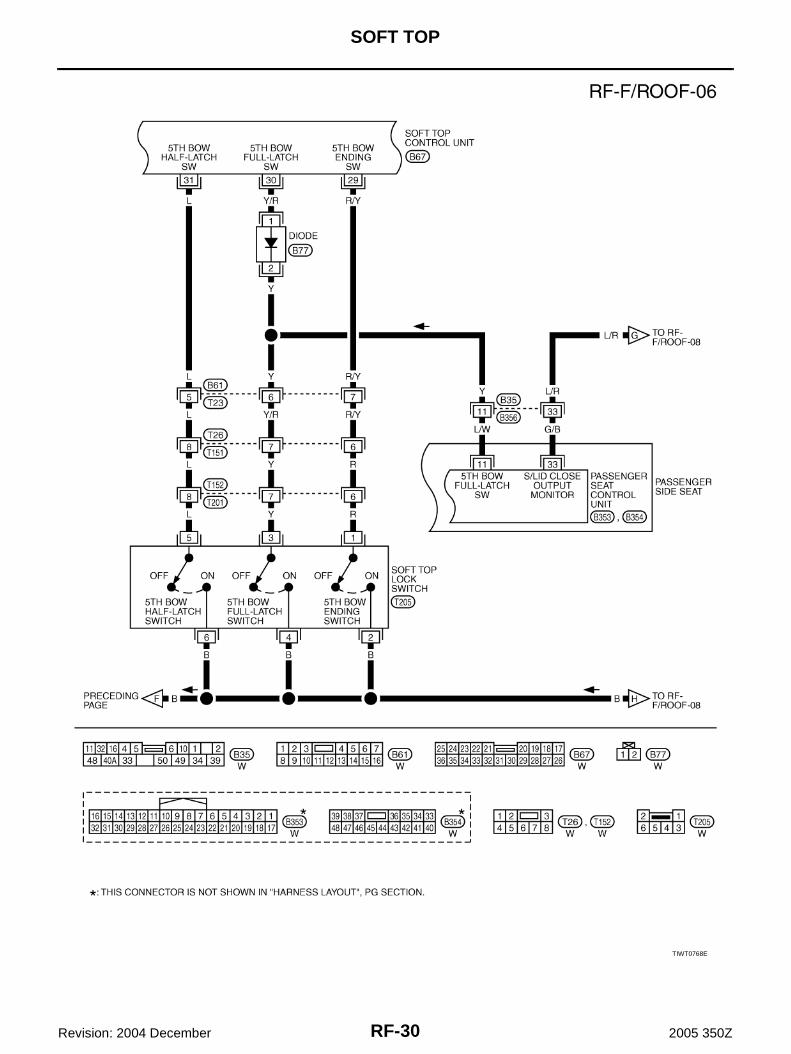
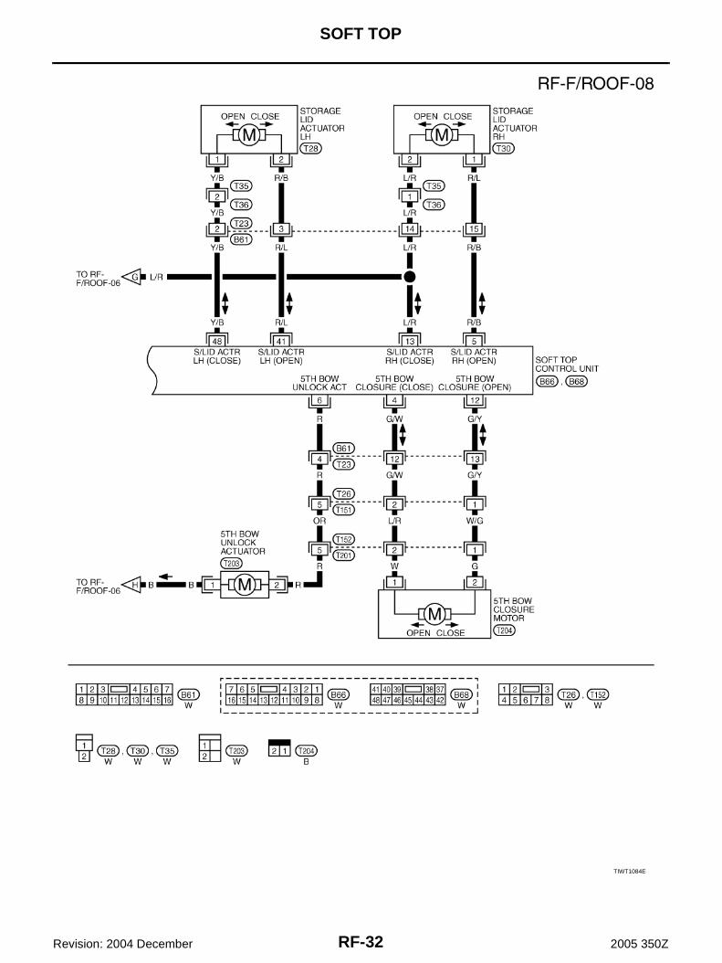
Wiring Diagram AIS005Z8
TIWT0765E

RF-26
SOFT TOP
Revision: 2004 December 2005 350Z
TIWT0525E
SOFT TOP
RF-27
C
D
E
F
G
H
J
K
L
M
A
B
RF
Revision: 2004 December 2005 350Z
TIWT0778E
RF-28
SOFT TOP
Revision: 2004 December 2005 350Z
TIWT0766E
SOFT TOP
RF-29
C
D
E
F
G
H
J
K
L
M
A
B
RF
Revision: 2004 December 2005 350Z
TIWT0767E
RF-30
SOFT TOP
Revision: 2004 December 2005 350Z
TIWT0768E

SOFT TOP
RF-31
C
D
E
F
G
H
J
K
L
M
A
B
RF
Revision: 2004 December 2005 350Z
TIWT0769E
RF-32
SOFT TOP
Revision: 2004 December 2005 350Z
TIWT1084E

SOFT TOP
RF-33
C
D
E
F
G
H
J
K
L
M
A
B
RF
Revision: 2004 December 2005 350Z
Terminal and Reference Value of Soft Top Control Unit AIS005Z9
CLOSE → OPEN OPERATIONThe operation chart for roof position. Refer to RF-19, "State Chart" .
TerminalWirecolor
ItemCondition
(Roof position: OP)Voltage (V)(Approx.)
1 W/R Battery power supply — Battery voltage
3 RRoof actuator RH
(OPEN) signal
OP8 → OP11 0 → Battery voltage → 0
Other than above 0
4 G/W5th bow closure motor
(CLOSE) signal— 0
5 R/BStorage lid actuator RH
(OPEN) signal
OP6 → OP70 → Battery voltage → 0
OP12
Other than above 0
6 R 5th bow unlock actuator signalOP2 → OP3 0 → Battery voltage → 0
Other than above 0
7 B Ground — 0
8 W/R Battery power supply — Battery voltage
10 YRoof actuator RH(CLOSE) signal
— 0
12 G/Y5th bow closure motor
(OPEN) signal
OP4 0 → Battery voltage → 0
Other than above 0
13 L/RStorage lid actuator RH
(CLOSE) signal
OP11 → OP12 0 → Battery voltage → 0
Other than above 0
14 W Speed signal (8 pulse)Speed meter operate
[When vehicle speed is Approx. 40km/h (25 MPH)]
15 OR Storage lid unlock actuator signalOP5 → OP6 0 → Battery voltage → 0
Other than above 0
16 B Ground — 0
17 GIgnition switch(ON or START)
Ignition switch(ON or START position)
Battery voltage
18 L/WSoft top switch(OPEN) signal
Soft top switchopen operate
0
Other than above 5
19 R/WSoft top switch(CLOSE) signal
Soft top switchclose operate
0
Other than above 5
20 W/BRoof full close detection switch
signalOP8 5 → 0
21 W/LRoof full open detection switch
signalOP11 5 → 0
22 W/RRoll bar interference prevention
switch signalOP9 5 → 0
PKIA1935E

RF-34
SOFT TOP
Revision: 2004 December 2005 350Z
23 W/G Speed signal (2 pulse)Speed meter operate
[When vehicle speed is Approx. 40 km/h (25 MPH)]
24 GStorage lid full close
detection switch (RH) signalOP5 → OP12 5 → 0 → 5
25 L/YStorage lid full close
detection switch (LH) signalOP6 → OP11 5 → 0 → 5
26 LG5th bow full open detection
switch signal
OP5 → OP7 5 → 0 → 5
OP10 5 → 0
27 W/G5th bow full close detection
switch signal
OP4 → OP8 5 → 0 → 5
OP9 5 → 0
29 R/Y 5th bow ending switch signal OP4 5 → 0
30 Y/R 5th bow full-latch switch signal OP4 5 → 0
31 L 5th bow half-latch switch signal OP3 5 → 0
32 WBody interference
prevention switch signalOP10 5 → 0
33 PStorage lid full open
detection switch signalOP7 → OP11 5 → 0 → 5
34 L/W Seat back position signal
When passenger seatinclines forward
0
Other than above 5
35 BR Indicator lamp signalOP1 → OP12 0
Other than above Battery voltage
36 Y/G Power window down signalOP1→OP11 0
Other than above 5
37 RRoof actuator LH (OPEN) signal
OP8 → OP11 0 → Battery voltage → 0
Other than above 0
38 P/L Brake pedal signal Brake pedal: Depressed Battery voltage
: Released 0
41 R/LStorage lid actuator LH
(OPEN) signal
OP6 → OP70 → Battery voltage → 0
OP12
Other than above 0
42 YRoof actuator LH(CLOSE) signal
— 0
44 G/R5th bow actuator(DOWN) signal
OP7 → OP8 0 → Battery voltage → 0
Other than above 0
45 G/Y5th bow actuator
(UP) signal
OP3 → OP50 → Battery voltage → 0
OP9 → OP10
Other than above 0
48 Y/BStorage lid actuator LH
(CLOSE) signal
OP11 → OP12 0 → Battery voltage → 0
Other than above 0
TerminalWirecolor
ItemCondition
(Roof position: OP)Voltage (V)(Approx.)
PIIB0078J

SOFT TOP
RF-35
C
D
E
F
G
H
J
K
L
M
A
B
RF
Revision: 2004 December 2005 350Z
OPEN → CLOSE OPERATIONThe operation chart for roof position. Refer to RF-21, "State Chart" .
TerminalWirecolor
ItemCondition
(Roof position: CL)Voltage (V)(Approx.)
1 W/R Battery power supply — Battery voltage
3 RRoof actuator RH
(OPEN) signal— 0
4 G/W5th bow closure motor
(CLOSE) signal
CL10 0 → Battery voltage → 0
Other than above 0
5 R/BStorage lid actuator RH
(OPEN) signal
CL2 → CL30 → Battery voltage → 0
CL8
Other than above 0
6 R 5th bow unlock actuator signal — 0
7 B Ground — 0
8 W/R Battery power supply — Battery voltage
10 YRoof actuator RH(CLOSE) signal
CL3 → CL6 0 → Battery voltage → 0
Other than above 0
12 G/Y5th bow closure motor
(OPEN) signal— 0
13 L/RStorage lid actuator RH
(CLOSE) signal
CL7 → CL8 0 → Battery voltage → 0
Other than above 0
14 W Speed signal (8 pulse)Speed meter operate
[When vehicle speed is Approx. 40 km/h (25 MPH)]
15 OR Storage lid unlock actuator signalCL1 → CL2 0 → Battery voltage → 0
Other than above 0
16 B Ground — 0
17 GIgnition switch(ON or START)
Ignition switch(ON or START position)
Battery voltage
18 L/WSoft top switch(OPEN) signal
Soft top switchopen operate
0
Other than above 5
19 R/WSoft top switch(CLOSE) signal
Soft top switchclose operate
0
Other than above 5
20 W/BRoof full close detection
switch signalCL6 0 → 5
21 W/LRoof full open detection switch
signalCL3 0 → 5
22 W/RRoll bar interference prevention
switch signalCL5 0 → 5
PKIA1935E

RF-36
SOFT TOP
Revision: 2004 December 2005 350Z
23 W/G Speed signal (2 pulse)Speed meter operate
[When vehicle speed is Approx. 40 km/h (25 MPH)]
24 GStorage lid full close
detection switch (RH) signalCL1 → CL8 5 → 0 → 5
25 L/YStorage lid full close
detection switch (LH) signalCL2 → CL7 5 → 0 → 5
26 LG5th bow full open detection
switch signal
CL4 0 → 5
CL7 5 → 0
CL8 0 → 5
27 W/G5th bow full close
detection switch signal
CL5 → CL6 0 → 5 → 0
CL9 0 → 5
29 R/Y 5th bow ending switch signal CL10 0 → 5
30 Y/R 5th bow full-latch switch signal CL10 0 → 5
31 L 5th bow half-latch switch signal CL9 → CL10 0 → 5
32 WBody interference
prevention switch signalCL3 0 → 5
33 PStorage lid full open
detection switch signalCL3 → CL7 5 → 0 → 5
34 L/W Seat back position signal
When passenger seatinclines forward
0
Other than above 5
35 BR Indicator lamp signalCL1 → CL10 0
Other than above Battery voltage
36 Y/G Power window down signalCL1 → CL10 0
Other than above 5
37 RRoof actuator LH
(OPEN) signal— 0
38 P/L Brake pedal signal Brake pedal: Depressed Battery voltage
: Released 0
41 R/LStorage lid actuator LH
(OPEN) signal
CL2 → CL30 → Battery voltage → 0
CL8
Other than above 0
42 YRoof actuator LH(CLOSE) signal
CL3 → CL6 0 → Battery voltage → 0
44 G/R5th bow actuator(DOWN) signal
CL4 → CL50 → Battery voltage → 0
CL8 → CL10
45 G/Y5th bow actuator
(UP) signalCL6 → CL7 0 → Battery voltage → 0
48 Y/BStorage lid actuator LH
(CLOSE) signal
CL7 → CL8 0 → Battery voltage → 0
Other than above 0
TerminalWirecolor
ItemCondition
(Roof position: CL)Voltage (V)(Approx.)
PIIB0078J
SOFT TOP
RF-37
C
D
E
F
G
H
J
K
L
M
A
B
RF
Revision: 2004 December 2005 350Z
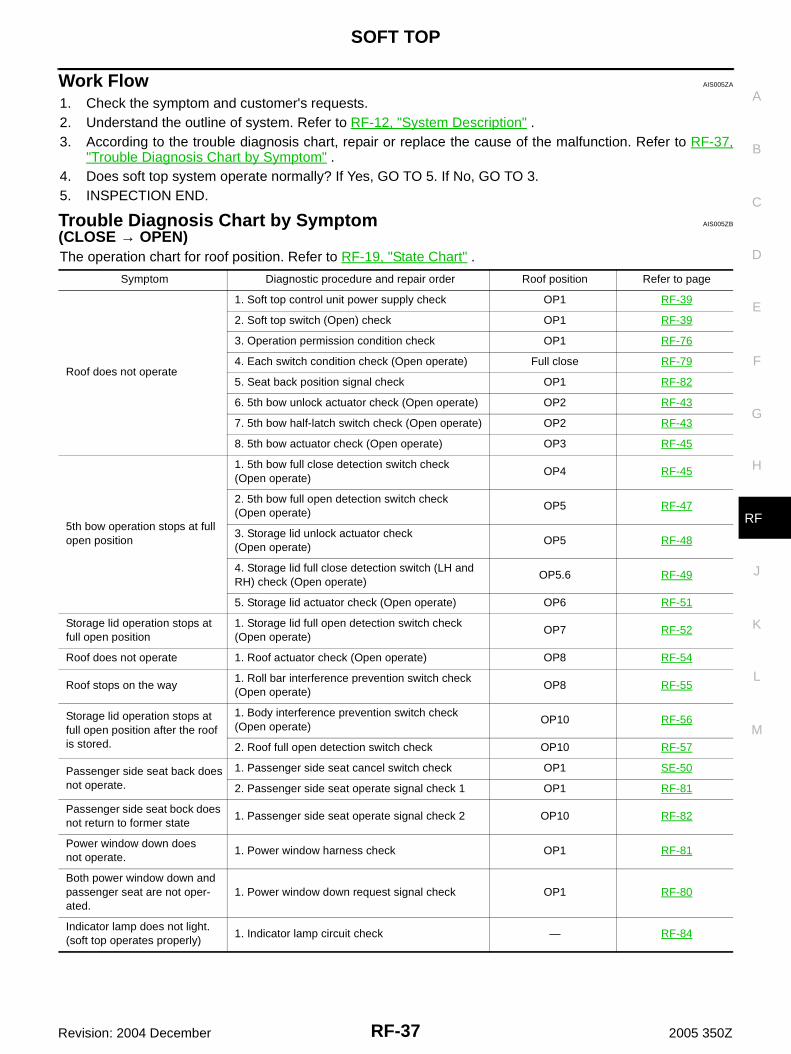
Work Flow AIS005ZA
1. Check the symptom and customer's requests.2. Understand the outline of system. Refer to RF-12, "System Description" .3. According to the trouble diagnosis chart, repair or replace the cause of the malfunction. Refer to RF-37,
"Trouble Diagnosis Chart by Symptom" .4. Does soft top system operate normally? If Yes, GO TO 5. If No, GO TO 3.5. INSPECTION END.
Trouble Diagnosis Chart by Symptom AIS005ZB
(CLOSE → OPEN)The operation chart for roof position. Refer to RF-19, "State Chart" .
Symptom Diagnostic procedure and repair order Roof position Refer to page
Roof does not operate
1. Soft top control unit power supply check OP1 RF-39
2. Soft top switch (Open) check OP1 RF-39
3. Operation permission condition check OP1 RF-76
4. Each switch condition check (Open operate) Full close RF-79
5. Seat back position signal check OP1 RF-82
6. 5th bow unlock actuator check (Open operate) OP2 RF-43
7. 5th bow half-latch switch check (Open operate) OP2 RF-43
8. 5th bow actuator check (Open operate) OP3 RF-45
5th bow operation stops at full open position
1. 5th bow full close detection switch check(Open operate)
OP4 RF-45
2. 5th bow full open detection switch check(Open operate)
OP5 RF-47
3. Storage lid unlock actuator check(Open operate)
OP5 RF-48
4. Storage lid full close detection switch (LH and RH) check (Open operate)
OP5.6 RF-49
5. Storage lid actuator check (Open operate) OP6 RF-51
Storage lid operation stops at full open position
1. Storage lid full open detection switch check (Open operate)
OP7 RF-52
Roof does not operate 1. Roof actuator check (Open operate) OP8 RF-54
Roof stops on the way1. Roll bar interference prevention switch check (Open operate)
OP8 RF-55
Storage lid operation stops at full open position after the roof is stored.
1. Body interference prevention switch check (Open operate)
OP10 RF-56
2. Roof full open detection switch check OP10 RF-57
Passenger side seat back doesnot operate.
1. Passenger side seat cancel switch check OP1 SE-50
2. Passenger side seat operate signal check 1 OP1 RF-81
Passenger side seat bock does not return to former state
1. Passenger side seat operate signal check 2 OP10 RF-82
Power window down doesnot operate.
1. Power window harness check OP1 RF-81
Both power window down and passenger seat are not oper-ated.
1. Power window down request signal check OP1 RF-80
Indicator lamp does not light. (soft top operates properly)
1. Indicator lamp circuit check — RF-84
RF-38
SOFT TOP
Revision: 2004 December 2005 350Z
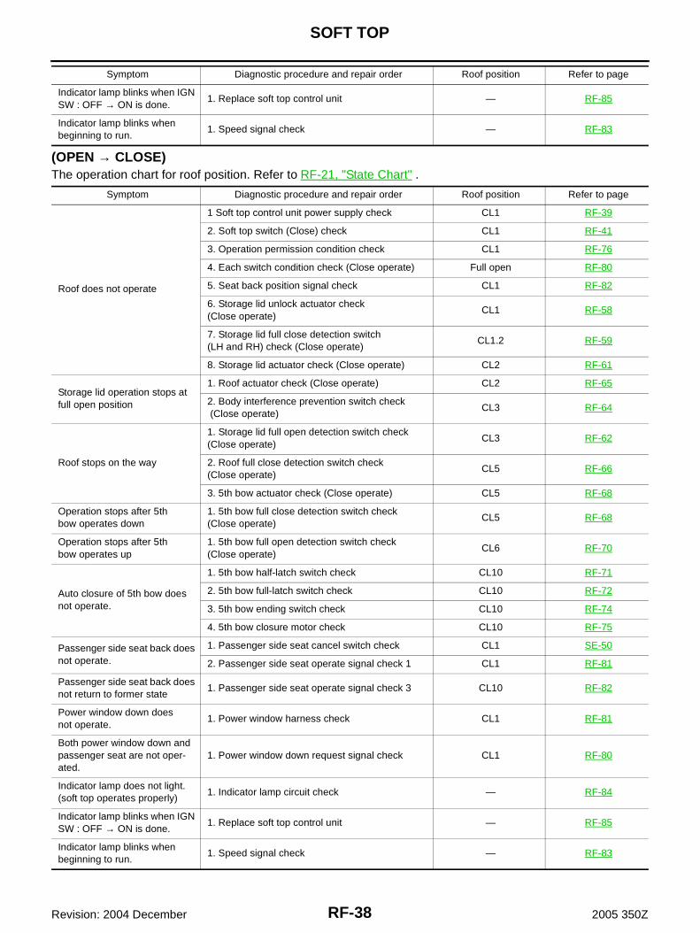
(OPEN → CLOSE)The operation chart for roof position. Refer to RF-21, "State Chart" .
Indicator lamp blinks when IGN SW : OFF → ON is done.
1. Replace soft top control unit — RF-85
Indicator lamp blinks when beginning to run.
1. Speed signal check — RF-83
Symptom Diagnostic procedure and repair order Roof position Refer to page
Symptom Diagnostic procedure and repair order Roof position Refer to page
Roof does not operate
1 Soft top control unit power supply check CL1 RF-39
2. Soft top switch (Close) check CL1 RF-41
3. Operation permission condition check CL1 RF-76
4. Each switch condition check (Close operate) Full open RF-80
5. Seat back position signal check CL1 RF-82
6. Storage lid unlock actuator check(Close operate)
CL1 RF-58
7. Storage lid full close detection switch (LH and RH) check (Close operate)
CL1.2 RF-59
8. Storage lid actuator check (Close operate) CL2 RF-61
Storage lid operation stops at full open position
1. Roof actuator check (Close operate) CL2 RF-65
2. Body interference prevention switch check (Close operate)
CL3 RF-64
Roof stops on the way
1. Storage lid full open detection switch check (Close operate)
CL3 RF-62
2. Roof full close detection switch check(Close operate)
CL5 RF-66
3. 5th bow actuator check (Close operate) CL5 RF-68
Operation stops after 5thbow operates down
1. 5th bow full close detection switch check(Close operate)
CL5 RF-68
Operation stops after 5thbow operates up
1. 5th bow full open detection switch check (Close operate)
CL6 RF-70
Auto closure of 5th bow does not operate.
1. 5th bow half-latch switch check CL10 RF-71
2. 5th bow full-latch switch check CL10 RF-72
3. 5th bow ending switch check CL10 RF-74
4. 5th bow closure motor check CL10 RF-75
Passenger side seat back does not operate.
1. Passenger side seat cancel switch check CL1 SE-50
2. Passenger side seat operate signal check 1 CL1 RF-81
Passenger side seat back does not return to former state
1. Passenger side seat operate signal check 3 CL10 RF-82
Power window down doesnot operate.
1. Power window harness check CL1 RF-81
Both power window down and passenger seat are not oper-ated.
1. Power window down request signal check CL1 RF-80
Indicator lamp does not light. (soft top operates properly)
1. Indicator lamp circuit check — RF-84
Indicator lamp blinks when IGN SW : OFF → ON is done.
1. Replace soft top control unit — RF-85
Indicator lamp blinks when beginning to run.
1. Speed signal check — RF-83
SOFT TOP
RF-39
C
D
E
F
G
H
J
K
L
M
A
B
RF
Revision: 2004 December 2005 350Z
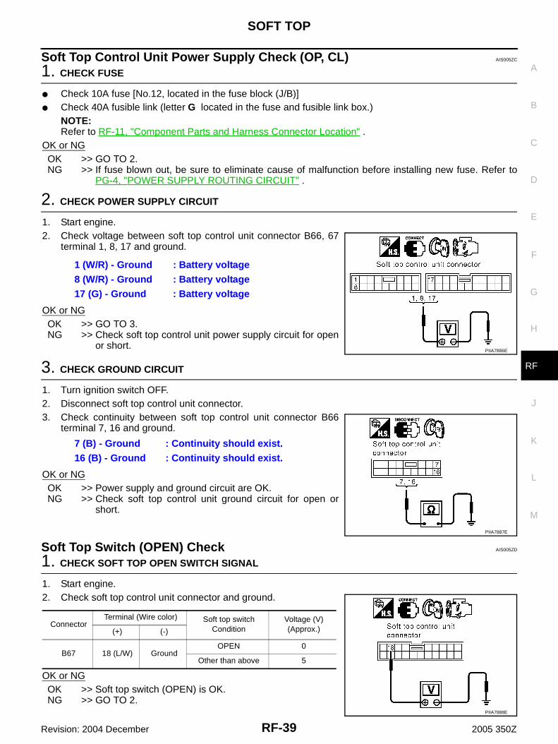
Soft Top Control Unit Power Supply Check (OP, CL) AIS005ZC
1. CHECK FUSE
● Check 10A fuse [No.12, located in the fuse block (J/B)]● Check 40A fusible link (letter G located in the fuse and fusible link box.)
NOTE:Refer to RF-11, "Component Parts and Harness Connector Location" .
OK or NGOK >> GO TO 2.NG >> If fuse blown out, be sure to eliminate cause of malfunction before installing new fuse. Refer to
PG-4, "POWER SUPPLY ROUTING CIRCUIT" .
2. CHECK POWER SUPPLY CIRCUIT
1. Start engine.2. Check voltage between soft top control unit connector B66, 67
terminal 1, 8, 17 and ground.
OK or NGOK >> GO TO 3.NG >> Check soft top control unit power supply circuit for open
or short.
3. CHECK GROUND CIRCUIT
1. Turn ignition switch OFF.2. Disconnect soft top control unit connector.3. Check continuity between soft top control unit connector B66
terminal 7, 16 and ground.
OK or NGOK >> Power supply and ground circuit are OK.NG >> Check soft top control unit ground circuit for open or
short.
Soft Top Switch (OPEN) Check AIS005ZD
1. CHECK SOFT TOP OPEN SWITCH SIGNAL
1. Start engine.2. Check soft top control unit connector and ground.
OK or NGOK >> Soft top switch (OPEN) is OK.NG >> GO TO 2.
1 (W/R) - Ground : Battery voltage8 (W/R) - Ground : Battery voltage17 (G) - Ground : Battery voltage
PIIA7886E
7 (B) - Ground : Continuity should exist.16 (B) - Ground : Continuity should exist.
PIIA7887E
ConnectorTerminal (Wire color) Soft top switch
ConditionVoltage (V) (Approx.)(+) (-)
B67 18 (L/W) GroundOPEN 0
Other than above 5
PIIA7888E

RF-40
SOFT TOP
Revision: 2004 December 2005 350Z
2. CHECK SOFT TOP SWITCH GROUND CIRCUIT
1. Turn ignition switch OFF.2. Disconnect soft top switch connector.3. Check continuity between soft top switch connector M14 termi-
nal 1 and ground.
OK or NGOK >> GO TO 3.NG >> Repair or replace harness.
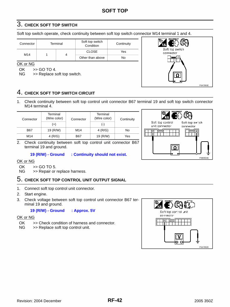
3. CHECK SOFT TOP SWITCH
Soft top switch operate, check continuity between soft top switch connector M14 terminal 1 and 3.
OK or NGOK >> GO TO 4.NG >> Replace soft top switch.
4. CHECK SOFT TOP SWITCH CIRCUIT
1. Check continuity between soft top control unit connector B67 terminal 18 and soft top switch connectorM14 terminal 3.
2. Check continuity between soft top control unit connector B67terminal 18 and ground.
OK or NGOK >> GO TO 5.NG >> Repair or replace harness.
1 (B) - Ground : Continuity should exist.
PIIA7889E
Connector TerminalSoft top switch
ConditionContinuity
M14 1 3OPEN Yes
Other than above No
PIIA7890E
Connector
Terminal (Wire color) Connector
Terminal (Wire color) Continuity
(+) (-)
B67 18 (L/W) M14 3 (L/B) No
M14 3 (L/B) B67 18 (L/W) Yes
18 (L/W) - Ground : Continuity should not exist.PIIB0833E

SOFT TOP
RF-41
C
D
E
F
G
H
J
K
L
M
A
B
RF
Revision: 2004 December 2005 350Z
5. CHECK SOFT TOP CONTROL UNIT OUTPUT SIGNAL
1. Connect soft top control unit connector.2. Start engine.3. Check voltage between soft top control unit connector B67 ter-
minal 18 and ground.
OK or NGOK >> Check condition of harness and connector.NG >> Replace soft top control unit.
Soft Top Switch (CLOSE) Check AIS005ZE
1. CHECK SOFT TOP CLOSE SWITCH SIGNAL
1. Start engine.2. Check soft top control unit connector and ground.
OK or NGOK >> Soft top switch (CLOSE) is OK.NG >> GO TO 2.
2. CHECK SOFT TOP SWITCH GROUND CIRCUIT
1. Turn ignition switch OFF.2. Disconnect soft top switch connector.3. Check continuity between soft top switch connector M14 termi-
nal 1 and ground.
OK or NGOK >> GO TO 3.NG >> Repair or replace harness.
18 (L/W) - Ground : Approx. 5V
PIIA7888E
ConnectorTerminal (Wire color) Soft top
switch ConditionVoltage (V)(Approx.)(+) (-)
B67 19 (R/W) GroundCLOSE 0
Other than above 5
PIIA7892E
1 (B) - Ground : Continuity should exist.
PIIA7889E
RF-42
SOFT TOP
Revision: 2004 December 2005 350Z
3. CHECK SOFT TOP SWITCH
Soft top switch operate, check continuity between soft top switch connector M14 terminal 1 and 4.
OK or NGOK >> GO TO 4.NG >> Replace soft top switch.
4. CHECK SOFT TOP SWITCH CIRCUIT
1. Check continuity between soft top control unit connector B67 terminal 19 and soft top switch connectorM14 terminal 4.
2. Check continuity between soft top control unit connector B67terminal 19 and ground.
OK or NGOK >> GO TO 5.NG >> Repair or replace harness.
5. CHECK SOFT TOP CONTROL UNIT OUTPUT SIGNAL
1. Connect soft top control unit connector.2. Start engine.3. Check voltage between soft top control unit connector B67 ter-
minal 19 and ground.
OK or NGOK >> Check condition of harness and connector.NG >> Replace soft top control unit.
Connector TerminalSoft top switch
ConditionContinuity
M14 1 4CLOSE Yes
Other than above No
PIIA7893E
Connector
Terminal (Wire color) Connector
Terminal (Wire color) Continuity
(+) (-)
B67 19 (R/W) M14 4 (R/G) No
M14 4 (R/G) B67 19 (R/W) Yes
19 (R/W) - Ground : Continuity should not exist.PIIB0834E
19 (R/W) - Ground : Approx. 5V
PIIA7892E
SOFT TOP
RF-43
C
D
E
F
G
H
J
K
L
M
A
B
RF
Revision: 2004 December 2005 350Z
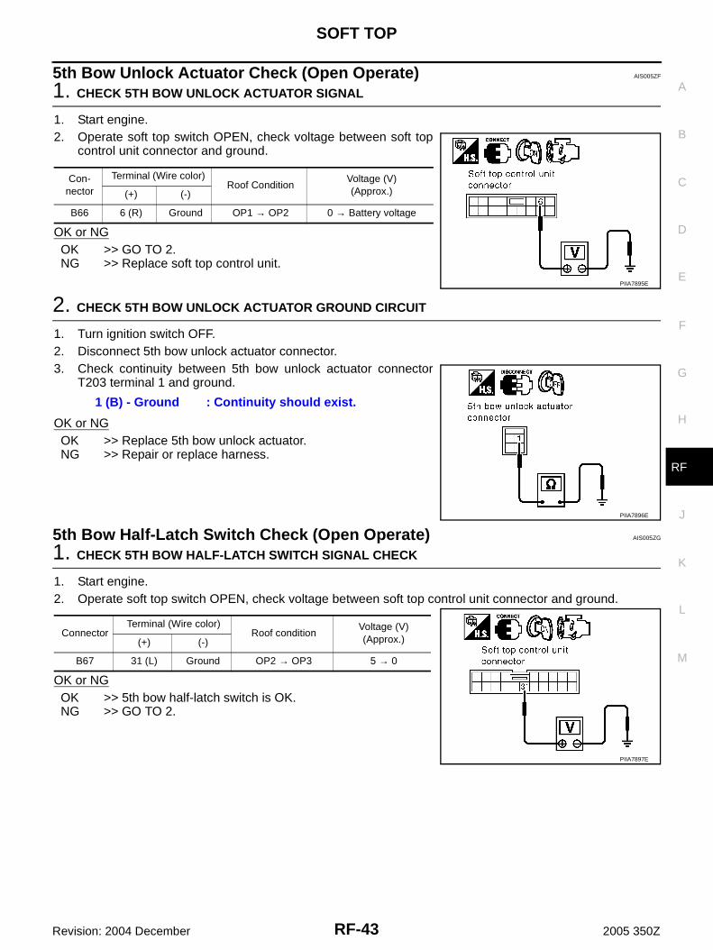
5th Bow Unlock Actuator Check (Open Operate) AIS005ZF
1. CHECK 5TH BOW UNLOCK ACTUATOR SIGNAL
1. Start engine.2. Operate soft top switch OPEN, check voltage between soft top
control unit connector and ground.
OK or NGOK >> GO TO 2. NG >> Replace soft top control unit.
2. CHECK 5TH BOW UNLOCK ACTUATOR GROUND CIRCUIT
1. Turn ignition switch OFF.2. Disconnect 5th bow unlock actuator connector.3. Check continuity between 5th bow unlock actuator connector
T203 terminal 1 and ground.
OK or NGOK >> Replace 5th bow unlock actuator.NG >> Repair or replace harness.
5th Bow Half-Latch Switch Check (Open Operate) AIS005ZG
1. CHECK 5TH BOW HALF-LATCH SWITCH SIGNAL CHECK
1. Start engine.2. Operate soft top switch OPEN, check voltage between soft top control unit connector and ground.
OK or NGOK >> 5th bow half-latch switch is OK.NG >> GO TO 2.
Con-nector
Terminal (Wire color)Roof Condition
Voltage (V)(Approx.)(+) (-)
B66 6 (R) Ground OP1 → OP2 0 → Battery voltage
PIIA7895E
1 (B) - Ground : Continuity should exist.
PIIA7896E
ConnectorTerminal (Wire color)
Roof conditionVoltage (V)(Approx.)(+) (-)
B67 31 (L) Ground OP2 → OP3 5 → 0
PIIA7897E
RF-44
SOFT TOP
Revision: 2004 December 2005 350Z
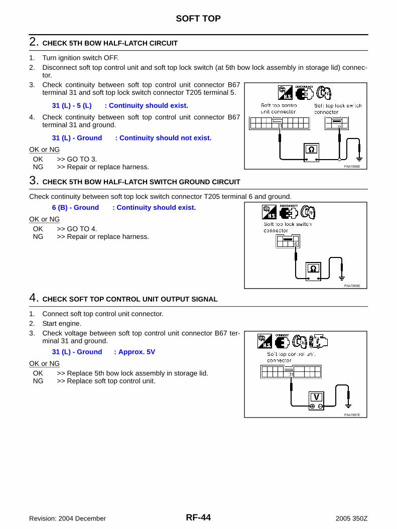
2. CHECK 5TH BOW HALF-LATCH CIRCUIT
1. Turn ignition switch OFF.2. Disconnect soft top control unit and soft top lock switch (at 5th bow lock assembly in storage lid) connec-
tor.3. Check continuity between soft top control unit connector B67
terminal 31 and soft top lock switch connector T205 terminal 5.
4. Check continuity between soft top control unit connector B67terminal 31 and ground.
OK or NGOK >> GO TO 3.NG >> Repair or replace harness.
3. CHECK 5TH BOW HALF-LATCH SWITCH GROUND CIRCUIT
Check continuity between soft top lock switch connector T205 terminal 6 and ground.
OK or NGOK >> GO TO 4. NG >> Repair or replace harness.
4. CHECK SOFT TOP CONTROL UNIT OUTPUT SIGNAL
1. Connect soft top control unit connector.2. Start engine.3. Check voltage between soft top control unit connector B67 ter-
minal 31 and ground.
OK or NGOK >> Replace 5th bow lock assembly in storage lid.NG >> Replace soft top control unit.
31 (L) - 5 (L) : Continuity should exist.
31 (L) - Ground : Continuity should not exist.
PIIA7898E
6 (B) - Ground : Continuity should exist.
PIIA7899E
31 (L) - Ground : Approx. 5V
PIIA7897E
SOFT TOP
RF-45
C
D
E
F
G
H
J
K
L
M
A
B
RF
Revision: 2004 December 2005 350Z
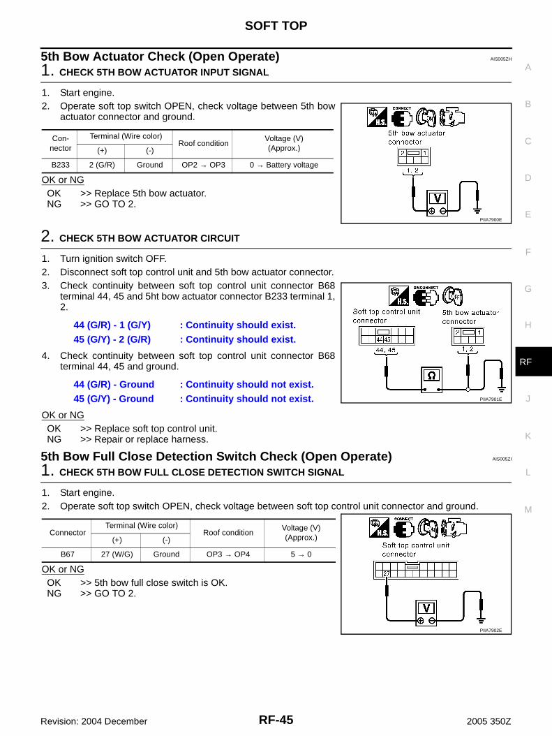
5th Bow Actuator Check (Open Operate) AIS005ZH
1. CHECK 5TH BOW ACTUATOR INPUT SIGNAL
1. Start engine.2. Operate soft top switch OPEN, check voltage between 5th bow
actuator connector and ground.
OK or NGOK >> Replace 5th bow actuator.NG >> GO TO 2.
2. CHECK 5TH BOW ACTUATOR CIRCUIT
1. Turn ignition switch OFF.2. Disconnect soft top control unit and 5th bow actuator connector.3. Check continuity between soft top control unit connector B68
terminal 44, 45 and 5ht bow actuator connector B233 terminal 1,2.
4. Check continuity between soft top control unit connector B68terminal 44, 45 and ground.
OK or NGOK >> Replace soft top control unit.NG >> Repair or replace harness.
5th Bow Full Close Detection Switch Check (Open Operate) AIS005ZI
1. CHECK 5TH BOW FULL CLOSE DETECTION SWITCH SIGNAL
1. Start engine.2. Operate soft top switch OPEN, check voltage between soft top control unit connector and ground.
OK or NGOK >> 5th bow full close switch is OK.NG >> GO TO 2.
Con-nector
Terminal (Wire color)Roof condition
Voltage (V) (Approx.)(+) (-)
B233 2 (G/R) Ground OP2 → OP3 0 → Battery voltage
PIIA7900E
44 (G/R) - 1 (G/Y) : Continuity should exist.45 (G/Y) - 2 (G/R) : Continuity should exist.
44 (G/R) - Ground : Continuity should not exist.45 (G/Y) - Ground : Continuity should not exist. PIIA7901E
ConnectorTerminal (Wire color)
Roof conditionVoltage (V)(Approx.)(+) (-)
B67 27 (W/G) Ground OP3 → OP4 5 → 0
PIIA7902E
RF-46
SOFT TOP
Revision: 2004 December 2005 350Z
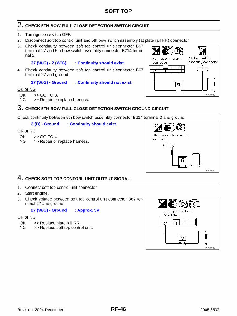
2. CHECK 5TH BOW FULL CLOSE DETECTION SWITCH CIRCUIT
1. Turn ignition switch OFF.2. Disconnect soft top control unit and 5th bow switch assembly (at plate rail RR) connector.3. Check continuity between soft top control unit connector B67
terminal 27 and 5th bow switch assembly connector B214 termi-nal 2.
4. Check continuity between soft top control unit connector B67terminal 27 and ground.
OK or NGOK >> GO TO 3.NG >> Repair or replace harness.
3. CHECK 5TH BOW FULL CLOSE DETECTION SWITCH GROUND CIRCUIT
Check continuity between 5th bow switch assembly connector B214 terminal 3 and ground.
OK or NGOK >> GO TO 4.NG >> Repair or replace harness.
4. CHECK SOFT TOP CONTORL UNIT OUTPUT SIGNAL
1. Connect soft top control unit connector.2. Start engine.3. Check voltage between soft top control unit connector B67 ter-
minal 27 and ground.
OK or NGOK >> Replace plate rail RR.NG >> Replace soft top control unit.
27 (W/G) - 2 (W/G) : Continuity should exist.
27 (W/G) - Ground : Continuity should not exist.
PIIA7903E
3 (B) - Ground : Continuity should exist.
PIIA7904E
27 (W/G) - Ground : Approx. 5V
PIIA7902E
SOFT TOP
RF-47
C
D
E
F
G
H
J
K
L
M
A
B
RF
Revision: 2004 December 2005 350Z
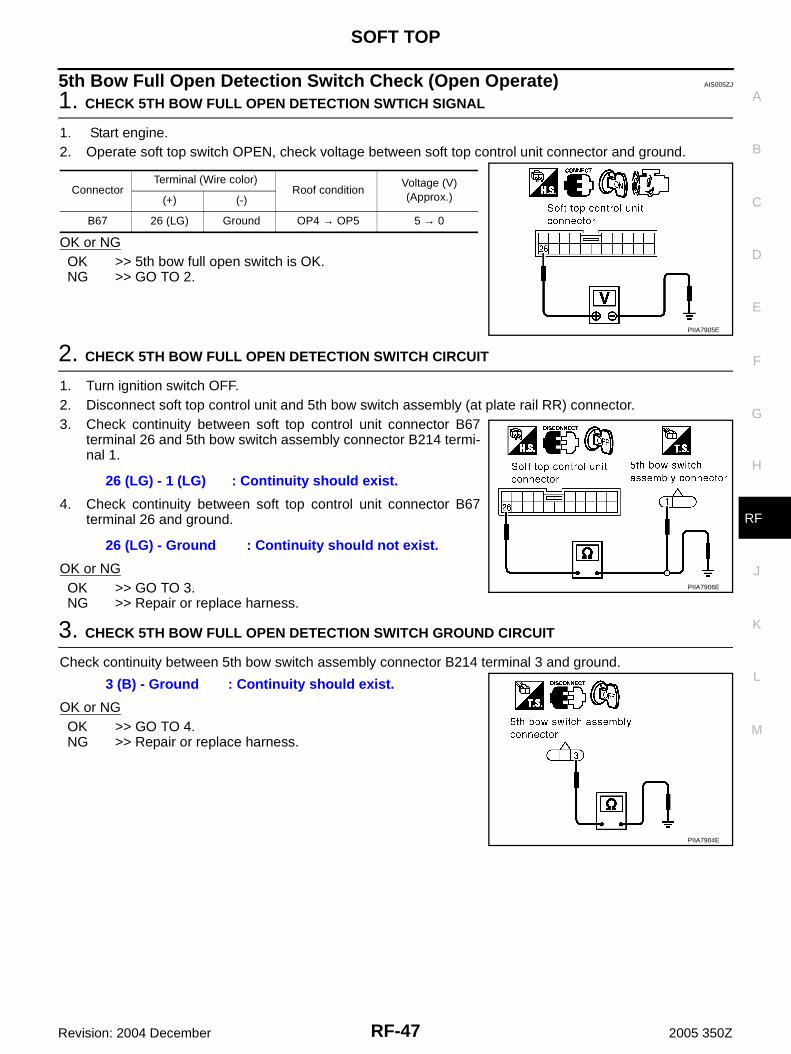
5th Bow Full Open Detection Switch Check (Open Operate) AIS005ZJ
1. CHECK 5TH BOW FULL OPEN DETECTION SWTICH SIGNAL
1. Start engine.2. Operate soft top switch OPEN, check voltage between soft top control unit connector and ground.
OK or NGOK >> 5th bow full open switch is OK.NG >> GO TO 2.
2. CHECK 5TH BOW FULL OPEN DETECTION SWITCH CIRCUIT
1. Turn ignition switch OFF.2. Disconnect soft top control unit and 5th bow switch assembly (at plate rail RR) connector.3. Check continuity between soft top control unit connector B67
terminal 26 and 5th bow switch assembly connector B214 termi-nal 1.
4. Check continuity between soft top control unit connector B67terminal 26 and ground.
OK or NGOK >> GO TO 3.NG >> Repair or replace harness.
3. CHECK 5TH BOW FULL OPEN DETECTION SWITCH GROUND CIRCUIT
Check continuity between 5th bow switch assembly connector B214 terminal 3 and ground.
OK or NGOK >> GO TO 4.NG >> Repair or replace harness.
ConnectorTerminal (Wire color)
Roof conditionVoltage (V)(Approx.)(+) (-)
B67 26 (LG) Ground OP4 → OP5 5 → 0
PIIA7905E
26 (LG) - 1 (LG) : Continuity should exist.
26 (LG) - Ground : Continuity should not exist.
PIIA7906E
3 (B) - Ground : Continuity should exist.
PIIA7904E
RF-48
SOFT TOP
Revision: 2004 December 2005 350Z
4. CHECK SOFT TOP CONTORL UNIT OUTPUT SIGNAL
1. Connect soft top control unit connector.2. Start engine.3. Check voltage between soft top control unit connector B67 ter-
minal 26 and ground.
OK or NGOK >> Replace plate rail RR.NG >> Replace soft top control unit.
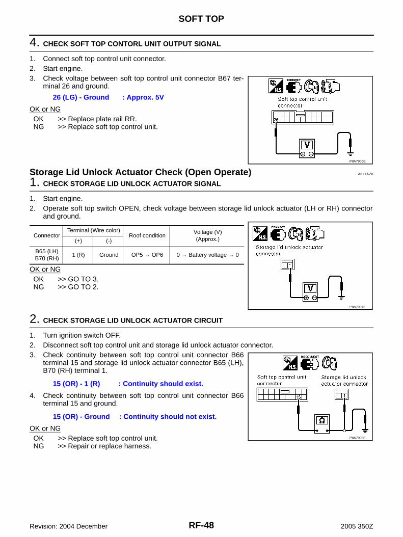
Storage Lid Unlock Actuator Check (Open Operate) AIS005ZK
1. CHECK STORAGE LID UNLOCK ACTUATOR SIGNAL
1. Start engine.2. Operate soft top switch OPEN, check voltage between storage lid unlock actuator (LH or RH) connector
and ground.
OK or NGOK >> GO TO 3.NG >> GO TO 2.
2. CHECK STORAGE LID UNLOCK ACTUATOR CIRCUIT
1. Turn ignition switch OFF.2. Disconnect soft top control unit and storage lid unlock actuator connector.3. Check continuity between soft top control unit connector B66
terminal 15 and storage lid unlock actuator connector B65 (LH),B70 (RH) terminal 1.
4. Check continuity between soft top control unit connector B66terminal 15 and ground.
OK or NGOK >> Replace soft top control unit.NG >> Repair or replace harness.
26 (LG) - Ground : Approx. 5V
PIIA7905E
ConnectorTerminal (Wire color)
Roof conditionVoltage (V)(Approx.)(+) (-)
B65 (LH)B70 (RH)
1 (R) Ground OP5 → OP6 0 → Battery voltage → 0
PIIA7907E
15 (OR) - 1 (R) : Continuity should exist.
15 (OR) - Ground : Continuity should not exist.
PIIA7908E

SOFT TOP
RF-49
C
D
E
F
G
H
J
K
L
M
A
B
RF
Revision: 2004 December 2005 350Z
3. CHECK STORAGE LID UNLOCK ACTUATOR GROUND CIRCUIT
1. Turn ignition switch OFF.2. Disconnect storage lid unlock actuator connector.3. Check continuity between storage lid unlock actuator connector
B65 (LH), B70 (RH) terminal 2 and ground.
OK or NGOK >> Replace malfunction storage lid unlock actuator (LH or
RH).NG >> Repair or replace harness.
Storage Lid Full Close Detection Switch Check (Open Operate) AIS005ZL
1. CHECK STORAGE LID FULL CLOSE DETECTION SWITCH SIGNAL
1. Start engine.2. Operate soft top switch OPEN, check voltage between soft top control unit connector and ground.
OK or NGOK >> Storage lid full close detection switch is OK.NG >> GO TO 2.
2 (B) - Ground : Continuity should exist.
PIIA7909E
ConnectorTerminal (Wire color)
Roof conditionVoltage (V)(Approx.)(+) (-)
B6724 (G)
GroundOP5
5 → 025 (L/Y) OP6
PIIA7910E

RF-50
SOFT TOP
Revision: 2004 December 2005 350Z
2. CHECK STORAGE LID FULL CLOSE DETECTION SWITCH CIRCUIT
1. Turn ignition switch OFF.2. Disconnect soft top control unit and storage lid switch (close) connector.3. Check the following.– Continuity between soft top control unit connector B67 terminal
25 and storage lid switch LH (close) connector B64 terminal 1.
– Continuity between soft top control unit connector B67 terminal25 and ground.
4. Check the following.– Continuity between soft top control unit connector B67 terminal
24 and storage lid switch RH (close) connector B69 terminal 1.
– Continuity between soft top control unit connector B67 terminal24 and ground.
OK or NGOK >> GO TO 3.NG >> Repair or replace harness.
3. CHECK STORAGE LID FULL CLOSE DETECTION SWITCH GROUND CIRCUIT
Check continuity between storage lid switch (close) connector B64 (LH), B69 (RH) terminal 2 and ground.
OK or NGOK >> GO TO 4.NG >> Repair or replace harness.
25 (L/Y) - 1 (L/Y) : Continuity should exist.
25 (L/Y) - Ground : Continuity should not exist.
PIIA7911E
24 (G) - 1 (G) : Continuity should exist.
24 (G) - Ground : Continuity should not exist.
PIIA7912E
2 (B) - Ground : Continuity should exist.
PIIA7913E
SOFT TOP
RF-51
C
D
E
F
G
H
J
K
L
M
A
B
RF
Revision: 2004 December 2005 350Z
4. CHECK SOFT TOP CONTROL UNIT OUTPUT SIGNAL
1. Connect soft top control unit connector.2. Start engine.3. Check voltage between soft top control unit connector B67 ter-
minal 24, 25 and ground.
OK or NGOK >> Replace malfunction storage lid full close detection
switch (LH or RH).NG >> Replace soft top control unit.
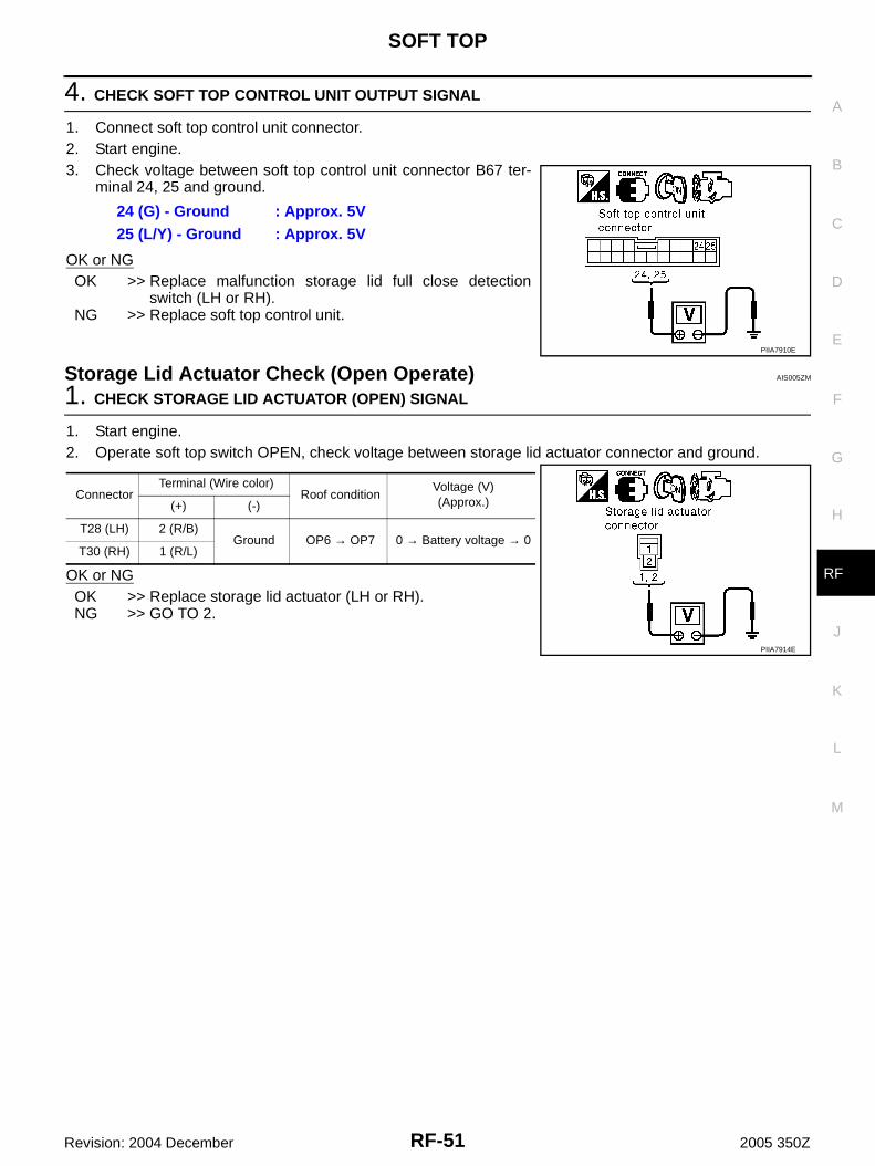
Storage Lid Actuator Check (Open Operate) AIS005ZM
1. CHECK STORAGE LID ACTUATOR (OPEN) SIGNAL
1. Start engine.2. Operate soft top switch OPEN, check voltage between storage lid actuator connector and ground.
OK or NGOK >> Replace storage lid actuator (LH or RH).NG >> GO TO 2.
24 (G) - Ground : Approx. 5V25 (L/Y) - Ground : Approx. 5V
PIIA7910E
ConnectorTerminal (Wire color)
Roof conditionVoltage (V)(Approx.)(+) (-)
T28 (LH) 2 (R/B)Ground OP6 → OP7 0 → Battery voltage → 0
T30 (RH) 1 (R/L)
PIIA7914E
RF-52
SOFT TOP
Revision: 2004 December 2005 350Z
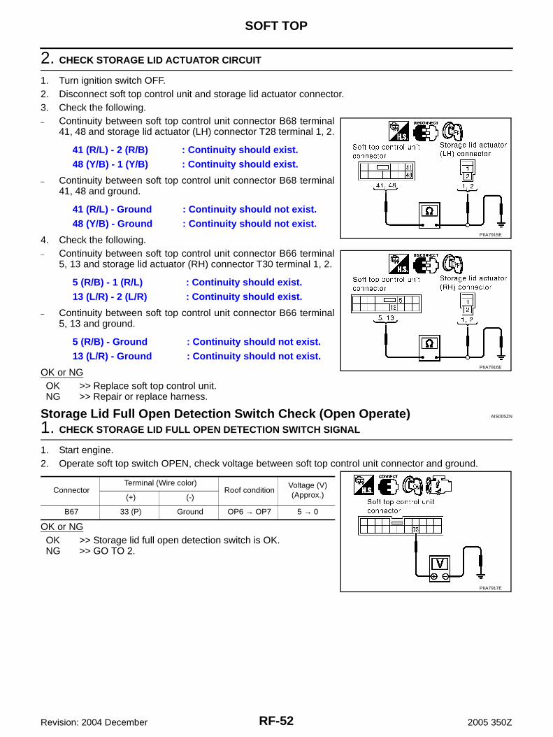
2. CHECK STORAGE LID ACTUATOR CIRCUIT
1. Turn ignition switch OFF.2. Disconnect soft top control unit and storage lid actuator connector.3. Check the following.– Continuity between soft top control unit connector B68 terminal
41, 48 and storage lid actuator (LH) connector T28 terminal 1, 2.
– Continuity between soft top control unit connector B68 terminal41, 48 and ground.
4. Check the following.– Continuity between soft top control unit connector B66 terminal
5, 13 and storage lid actuator (RH) connector T30 terminal 1, 2.
– Continuity between soft top control unit connector B66 terminal5, 13 and ground.
OK or NGOK >> Replace soft top control unit.NG >> Repair or replace harness.
Storage Lid Full Open Detection Switch Check (Open Operate) AIS005ZN
1. CHECK STORAGE LID FULL OPEN DETECTION SWITCH SIGNAL
1. Start engine.2. Operate soft top switch OPEN, check voltage between soft top control unit connector and ground.
OK or NGOK >> Storage lid full open detection switch is OK.NG >> GO TO 2.
41 (R/L) - 2 (R/B) : Continuity should exist.48 (Y/B) - 1 (Y/B) : Continuity should exist.
41 (R/L) - Ground : Continuity should not exist.48 (Y/B) - Ground : Continuity should not exist.
5 (R/B) - 1 (R/L) : Continuity should exist.13 (L/R) - 2 (L/R) : Continuity should exist.
5 (R/B) - Ground : Continuity should not exist.13 (L/R) - Ground : Continuity should not exist.
PIIA7915E
PIIA7916E
ConnectorTerminal (Wire color)
Roof conditionVoltage (V)(Approx.)(+) (-)
B67 33 (P) Ground OP6 → OP7 5 → 0
PIIA7917E
SOFT TOP
RF-53
C
D
E
F
G
H
J
K
L
M
A
B
RF
Revision: 2004 December 2005 350Z
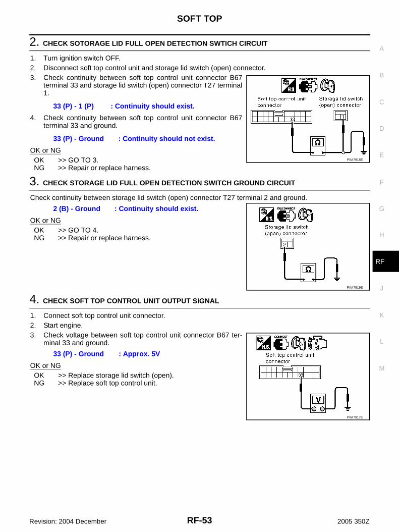
2. CHECK SOTORAGE LID FULL OPEN DETECTION SWTICH CIRCUIT
1. Turn ignition switch OFF.2. Disconnect soft top control unit and storage lid switch (open) connector.3. Check continuity between soft top control unit connector B67
terminal 33 and storage lid switch (open) connector T27 terminal1.
4. Check continuity between soft top control unit connector B67terminal 33 and ground.
OK or NGOK >> GO TO 3.NG >> Repair or replace harness.
3. CHECK STORAGE LID FULL OPEN DETECTION SWITCH GROUND CIRCUIT
Check continuity between storage lid switch (open) connector T27 terminal 2 and ground.
OK or NGOK >> GO TO 4.NG >> Repair or replace harness.
4. CHECK SOFT TOP CONTROL UNIT OUTPUT SIGNAL
1. Connect soft top control unit connector.2. Start engine.3. Check voltage between soft top control unit connector B67 ter-
minal 33 and ground.
OK or NGOK >> Replace storage lid switch (open).NG >> Replace soft top control unit.
33 (P) - 1 (P) : Continuity should exist.
33 (P) - Ground : Continuity should not exist.
PIIA7918E
2 (B) - Ground : Continuity should exist.
PIIA7919E
33 (P) - Ground : Approx. 5V
PIIA7917E
RF-54
SOFT TOP
Revision: 2004 December 2005 350Z
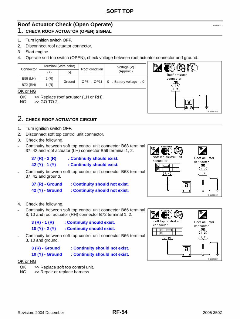
Roof Actuator Check (Open Operate) AIS005ZO
1. CHECK ROOF ACTUATOR (OPEN) SIGNAL
1. Turn ignition switch OFF.2. Disconnect roof actuator connector.3. Start engine.4. Operate soft top switch (OPEN), check voltage between roof actuator connector and ground.
OK or NGOK >> Replace roof actuator (LH or RH).NG >> GO TO 2.
2. CHECK ROOF ACTUATOR CIRCUIT
1. Turn ignition switch OFF.2. Disconnect soft top control unit connector.3. Check the following.– Continuity between soft top control unit connector B68 terminal
37, 42 and roof actuator (LH) connector B59 terminal 1, 2.
– Continuity between soft top control unit connector B68 terminal37, 42 and ground.
4. Check the following.– Continuity between soft top control unit connector B66 terminal
3, 10 and roof actuator (RH) connector B72 terminal 1, 2.
– Continuity between soft top control unit connector B66 terminal3, 10 and ground.
OK or NGOK >> Replace soft top control unit.NG >> Repair or replace harness.
Connector Terminal (Wire color)
Roof conditionVoltage (V)(Approx.)(+) (-)
B59 (LH) 2 (R)Ground OP8 → OP11 0 → Battery voltage → 0
B72 (RH) 1 (R)
PIIA7920E
37 (R) - 2 (R) : Continuity should exist.42 (Y) - 1 (Y) : Continuity should exist.
37 (R) - Ground : Continuity should not exist.42 (Y) - Ground : Continuity should not exist.
PIIA7921E
3 (R) - 1 (R) : Continuity should exist.10 (Y) - 2 (Y) : Continuity should exist.
3 (R) - Ground : Continuity should not exist.10 (Y) - Ground : Continuity should not exist.
PIIA7922E
SOFT TOP
RF-55
C
D
E
F
G
H
J
K
L
M
A
B
RF
Revision: 2004 December 2005 350Z
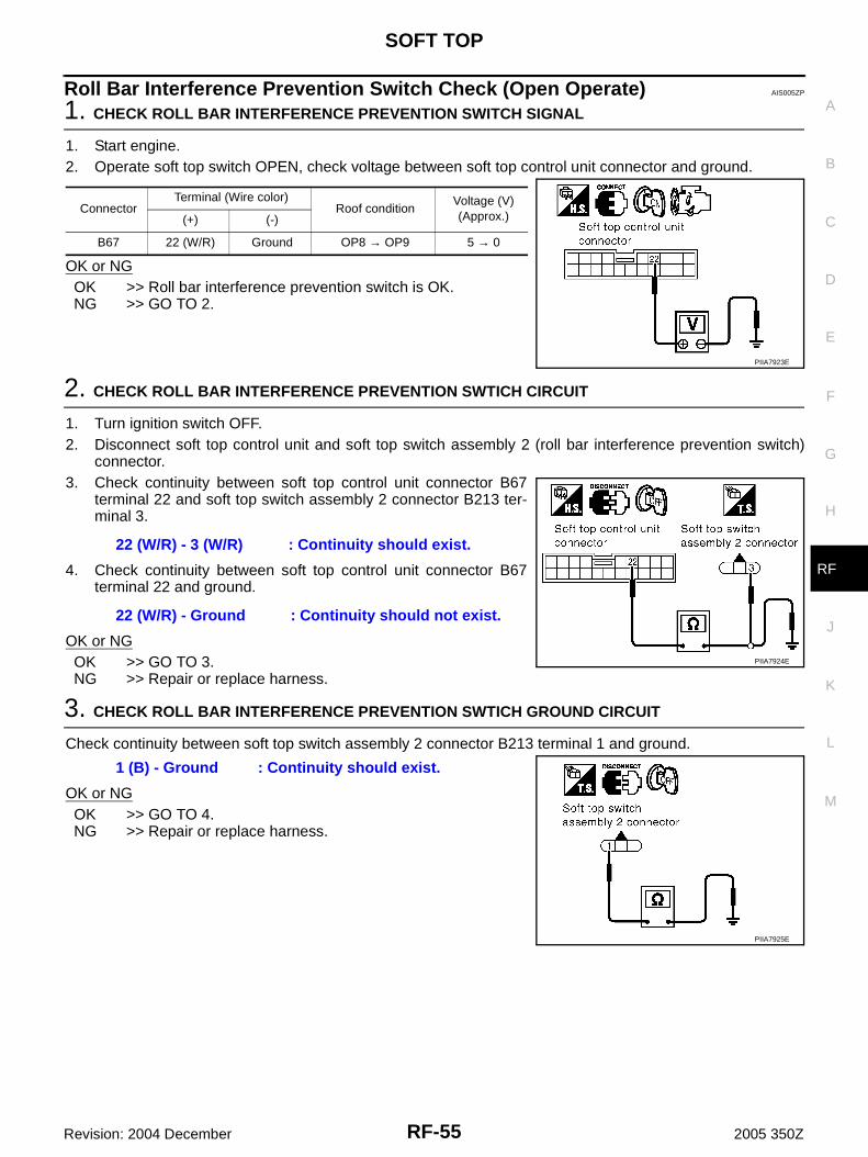
Roll Bar Interference Prevention Switch Check (Open Operate) AIS005ZP
1. CHECK ROLL BAR INTERFERENCE PREVENTION SWITCH SIGNAL
1. Start engine.2. Operate soft top switch OPEN, check voltage between soft top control unit connector and ground.
OK or NGOK >> Roll bar interference prevention switch is OK.NG >> GO TO 2.
2. CHECK ROLL BAR INTERFERENCE PREVENTION SWTICH CIRCUIT
1. Turn ignition switch OFF.2. Disconnect soft top control unit and soft top switch assembly 2 (roll bar interference prevention switch)
connector.3. Check continuity between soft top control unit connector B67
terminal 22 and soft top switch assembly 2 connector B213 ter-minal 3.
4. Check continuity between soft top control unit connector B67terminal 22 and ground.
OK or NGOK >> GO TO 3.NG >> Repair or replace harness.
3. CHECK ROLL BAR INTERFERENCE PREVENTION SWTICH GROUND CIRCUIT
Check continuity between soft top switch assembly 2 connector B213 terminal 1 and ground.
OK or NGOK >> GO TO 4.NG >> Repair or replace harness.
ConnectorTerminal (Wire color)
Roof conditionVoltage (V)(Approx.)(+) (-)
B67 22 (W/R) Ground OP8 → OP9 5 → 0
PIIA7923E
22 (W/R) - 3 (W/R) : Continuity should exist.
22 (W/R) - Ground : Continuity should not exist.
PIIA7924E
1 (B) - Ground : Continuity should exist.
PIIA7925E
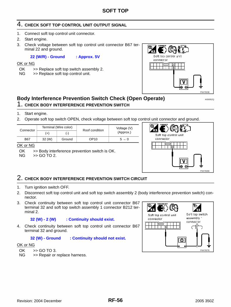
RF-56
SOFT TOP
Revision: 2004 December 2005 350Z
4. CHECK SOFT TOP CONTROL UNIT OUTPUT SIGNAL
1. Connect soft top control unit connector.2. Start engine.3. Check voltage between soft top control unit connector B67 ter-
minal 22 and ground.
OK or NGOK >> Replace soft top switch assembly 2.NG >> Replace soft top control unit.
Body Interference Prevention Switch Check (Open Operate) AIS005ZQ
1. CHECK BODY INTERFERENCE PREVENTION SWITCH
1. Start engine.2. Operate soft top switch OPEN, check voltage between soft top control unit connector and ground.
OK or NGOK >> Body interference prevention switch is OK.NG >> GO TO 2.
2. CHECK BODY INTERFERENCE PREVENTION SWITCH CIRCUIT
1. Turn ignition switch OFF.2. Disconnect soft top control unit and soft top switch assembly 2 (body interference prevention switch) con-
nector.3. Check continuity between soft top control unit connector B67
terminal 32 and soft top switch assembly 1 connector B212 ter-minal 2.
4. Check continuity between soft top control unit connector B67terminal 32 and ground.
OK or NGOK >> GO TO 3.NG >> Repair or replace harness.
22 (W/R) - Ground : Approx. 5V
PIIA7923E
ConnectorTerminal (Wire color)
Roof conditionVoltage (V)(Approx.)(+) (-)
B67 32 (W) Ground OP10 5 → 0
PIIA7926E
32 (W) - 2 (W) : Continuity should exist.
32 (W) - Ground : Continuity should not exist.
PIIA7927E
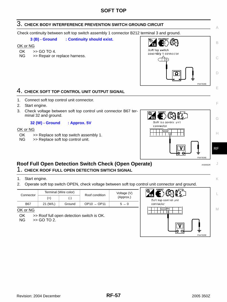
SOFT TOP
RF-57
C
D
E
F
G
H
J
K
L
M
A
B
RF
Revision: 2004 December 2005 350Z
3. CHECK BODY INTERFERENCE PREVENTION SWITCH GROUND CIRCUIT
Check continuity between soft top switch assembly 1 connector B212 terminal 3 and ground.
OK or NGOK >> GO TO 4.NG >> Repair or replace harness.
4. CHECK SOFT TOP CONTROL UNIT OUTPUT SIGNAL
1. Connect soft top control unit connector.2. Start engine.3. Check voltage between soft top control unit connector B67 ter-
minal 32 and ground.
OK or NGOK >> Replace soft top switch assembly 1.NG >> Replace soft top control unit.
Roof Full Open Detection Switch Check (Open Operate) AIS005ZR
1. CHECK ROOF FULL OPEN DETECTION SWTICH SIGNAL
1. Start engine.2. Operate soft top switch OPEN, check voltage between soft top control unit connector and ground.
OK or NGOK >> Roof full open detection switch is OK.NG >> GO TO 2.
3 (B) - Ground : Continuity should exist.
PIIA7928E
32 (W) - Ground : Approx. 5V
PIIA7926E
ConnectorTerminal (Wire color)
Roof conditionVoltage (V)(Approx.)(+) (-)
B67 21 (W/L) Ground OP10 → OP11 5 → 0
PIIA7929E
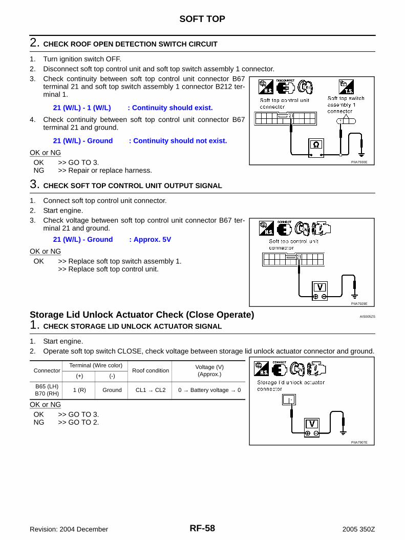
RF-58
SOFT TOP
Revision: 2004 December 2005 350Z
2. CHECK ROOF OPEN DETECTION SWITCH CIRCUIT
1. Turn ignition switch OFF.2. Disconnect soft top control unit and soft top switch assembly 1 connector.3. Check continuity between soft top control unit connector B67
terminal 21 and soft top switch assembly 1 connector B212 ter-minal 1.
4. Check continuity between soft top control unit connector B67terminal 21 and ground.
OK or NGOK >> GO TO 3.NG >> Repair or replace harness.
3. CHECK SOFT TOP CONTROL UNIT OUTPUT SIGNAL
1. Connect soft top control unit connector.2. Start engine.3. Check voltage between soft top control unit connector B67 ter-
minal 21 and ground.
OK or NGOK >> Replace soft top switch assembly 1.
>> Replace soft top control unit.
Storage Lid Unlock Actuator Check (Close Operate) AIS005ZS
1. CHECK STORAGE LID UNLOCK ACTUATOR SIGNAL
1. Start engine.2. Operate soft top switch CLOSE, check voltage between storage lid unlock actuator connector and ground.
OK or NGOK >> GO TO 3.NG >> GO TO 2.
21 (W/L) - 1 (W/L) : Continuity should exist.
21 (W/L) - Ground : Continuity should not exist.
PIIA7930E
21 (W/L) - Ground : Approx. 5V
PIIA7929E
ConnectorTerminal (Wire color)
Roof conditionVoltage (V)(Approx.)(+) (-)
B65 (LH)B70 (RH)
1 (R) Ground CL1 → CL2 0 → Battery voltage → 0
PIIA7907E
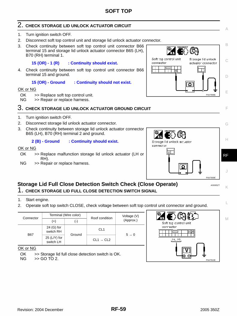
SOFT TOP
RF-59
C
D
E
F
G
H
J
K
L
M
A
B
RF
Revision: 2004 December 2005 350Z
2. CHECK STORAGE LID UNLOCK ACTUATOR CIRCUIT
1. Turn ignition switch OFF.2. Disconnect soft top control unit and storage lid unlock actuator connector.3. Check continuity between soft top control unit connector B66
terminal 15 and storage lid unlock actuator connector B65 (LH),B70 (RH) terminal 1.
4. Check continuity between soft top control unit connector B66terminal 15 and ground.
OK or NGOK >> Replace soft top control unit.NG >> Repair or replace harness.
3. CHECK STORAGE LID UNLOCK ACTUATOR GROUND CIRCUIT
1. Turn ignition switch OFF.2. Disconnect storage lid unlock actuator connector.3. Check continuity between storage lid unlock actuator connector
B65 (LH), B70 (RH) terminal 2 and ground.
OK or NGOK >> Replace malfunction storage lid unlock actuator (LH or
RH).NG >> Repair or replace harness.
Storage Lid Full Close Detection Switch Check (Close Operate) AIS005ZT
1. CHECK STORAGE LID FULL CLOSE DETECTION SWITCH SIGNAL
1. Start engine.2. Operate soft top switch CLOSE, check voltage between soft top control unit connector and ground.
OK or NGOK >> Storage lid full close detection switch is OK.NG >> GO TO 2.
15 (OR) - 1 (R) : Continuity should exist.
15 (OR) - Ground : Continuity should not exist.
PIIA7908E
2 (B) - Ground : Continuity should exist.
PIIA7909E
ConnectorTerminal (Wire color)
Roof conditionVoltage (V) (Approx.)(+) (-)
B67
24 (G) for switch RH
Ground
CL1
5 → 025 (L/Y) for switch LH
CL1 → CL2
PIIA7910E

RF-60
SOFT TOP
Revision: 2004 December 2005 350Z
2. CHECK STORAGE LID FULL CLOSE DETECTION SWTICH CIRCUIT
1. Turn ignition switch OFF.2. Disconnect soft top control unit and storage lid switch (close) connector.3. Check the following.– Continuity between soft top control unit connector B67 terminal
25 and storage lid switch LH (close) connector B64 terminal 1.
– Continuity between soft top control unit connector B67 terminal25 and ground.
4. Check the following.– Continuity between soft top control unit connector B67 terminal
24 and storage lid switch RH (close) connector B69 terminal 1.
– Continuity between soft top control unit connector B67 terminal24 and ground.
OK or NGOK >> GO TO 3.NG >> Repair or replace harness.
3. CHECK STORAGE LID FULL CLOSE DETECTION SWITCH GROUND CIRCUIT
Check continuity between storage lid switch (close) connector B64 (LH), B69 (RH) terminal 2 and ground.
OK or NGOK >> GO TO 4.NG >> Repair or replace harness.
25 (L/Y) - 1 (L/Y) : Continuity should exist.
25 (L/Y) - Ground : Continuity should not exist.
PIIA7911E
24 (G) - 1 (G) : Continuity should exist.
24 (G) - Ground : Continuity should not exist.
PIIA7912E
2 (B) - Ground : Continuity should exist.
PIIA7913E
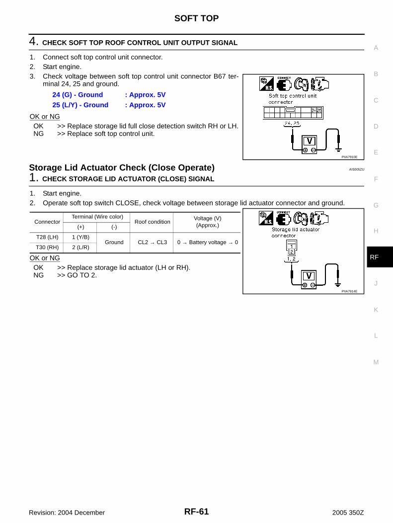
SOFT TOP
RF-61
C
D
E
F
G
H
J
K
L
M
A
B
RF
Revision: 2004 December 2005 350Z
4. CHECK SOFT TOP ROOF CONTROL UNIT OUTPUT SIGNAL
1. Connect soft top control unit connector.2. Start engine.3. Check voltage between soft top control unit connector B67 ter-
minal 24, 25 and ground.
OK or NGOK >> Replace storage lid full close detection switch RH or LH.NG >> Replace soft top control unit.
Storage Lid Actuator Check (Close Operate) AIS005ZU
1. CHECK STORAGE LID ACTUATOR (CLOSE) SIGNAL
1. Start engine.2. Operate soft top switch CLOSE, check voltage between storage lid actuator connector and ground.
OK or NGOK >> Replace storage lid actuator (LH or RH).NG >> GO TO 2.
24 (G) - Ground : Approx. 5V25 (L/Y) - Ground : Approx. 5V
PIIA7910E
ConnectorTerminal (Wire color)
Roof conditionVoltage (V)(Approx.)(+) (-)
T28 (LH) 1 (Y/B)Ground CL2 → CL3 0 → Battery voltage → 0
T30 (RH) 2 (L/R)
PIIA7914E
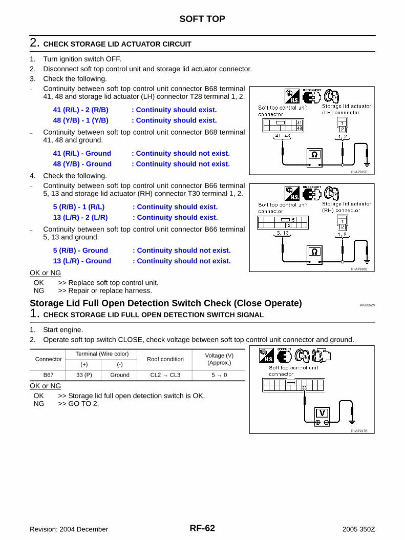
RF-62
SOFT TOP
Revision: 2004 December 2005 350Z
2. CHECK STORAGE LID ACTUATOR CIRCUIT
1. Turn ignition switch OFF.2. Disconnect soft top control unit and storage lid actuator connector.3. Check the following.– Continuity between soft top control unit connector B68 terminal
41, 48 and storage lid actuator (LH) connector T28 terminal 1, 2.
– Continuity between soft top control unit connector B68 terminal41, 48 and ground.
4. Check the following.– Continuity between soft top control unit connector B66 terminal
5, 13 and storage lid actuator (RH) connector T30 terminal 1, 2.
– Continuity between soft top control unit connector B66 terminal5, 13 and ground.
OK or NGOK >> Replace soft top control unit.NG >> Repair or replace harness.
Storage Lid Full Open Detection Switch Check (Close Operate) AIS005ZV
1. CHECK STORAGE LID FULL OPEN DETECTION SWITCH SIGNAL
1. Start engine.2. Operate soft top switch CLOSE, check voltage between soft top control unit connector and ground.
OK or NGOK >> Storage lid full open detection switch is OK.NG >> GO TO 2.
41 (R/L) - 2 (R/B) : Continuity should exist.48 (Y/B) - 1 (Y/B) : Continuity should exist.
41 (R/L) - Ground : Continuity should not exist.48 (Y/B) - Ground : Continuity should not exist.
5 (R/B) - 1 (R/L) : Continuity should exist.13 (L/R) - 2 (L/R) : Continuity should exist.
5 (R/B) - Ground : Continuity should not exist.13 (L/R) - Ground : Continuity should not exist.
PIIA7915E
PIIA7916E
ConnectorTerminal (Wire color)
Roof conditionVoltage (V)(Approx.)(+) (-)
B67 33 (P) Ground CL2 → CL3 5 → 0
PIIA7917E

SOFT TOP
RF-63
C
D
E
F
G
H
J
K
L
M
A
B
RF
Revision: 2004 December 2005 350Z
2. CHECK SOTORAGE LID FULL OPEN DETECTION SWITCH CIRCUIT
1. Turn ignition switch OFF.2. Disconnect soft top control unit and storage lid switch (open) connector.3. Check continuity between soft top control unit connector B67
terminal 33 and storage lid switch (open) connector T27 terminal1.
4. Check continuity between soft top control unit connector B67terminal 33 and ground.
OK or NGOK >> GO TO 3.NG >> Repair or replace harness.
3. CHECK STORAGE LID FULL OPEN DETECTION SWITCH GROUND CIRCUIT
Check continuity between storage lid switch (open) connector T27 terminal 2 and ground.
OK or NGOK >> GO TO 4.NG >> Repair or replace harness.
4. CHECK SOFT TOP CONTROL UNIT OUTPUT SIGNAL
1. Connect soft top control unit connector.2. Start engine.3. Check voltage between soft top control unit connector B67 ter-
minal 33 and ground.
OK or NGOK >> Replace storage lid switch (open).NG >> Replace soft top control unit.
33 (P) - 1 (P) : Continuity should exist.
33 (P) - Ground : Continuity should not exist.
PIIA7918E
2 (B) - Ground : Continuity should exist.
PIIA7919E
33 (P) - Ground : Approx. 5V
PIIA7917E

RF-64
SOFT TOP
Revision: 2004 December 2005 350Z
Body Interference Prevention Switch Check (Close Operate) AIS005ZW
1. CHECK BODY INTERFERENCE PREVENTION SWITCH
1. Start engine.2. Operate soft top switch CLOSE, check voltage between soft top control unit connector and ground.
OK or NGOK >> Body interference prevention switch is OK.NG >> GO TO 2.
2. CHECK BODY INTERFERENCE PREVENTION SWITCH CIRCUIT
1. Turn ignition switch OFF.2. Disconnect soft top control unit and soft top switch assembly 1 (body interference prevention switch) con-
nector.3. Check continuity between soft top control unit connector B67
terminal 32 and soft top switch assembly 1 connector B212 ter-minal 2.
4. Check continuity between soft top control unit connector B67terminal 32 and ground.
OK or NGOK >> GO TO 3.NG >> Repair or replace harness.
3. CHECK BODY INTERFERENCE PREVENTION SWITCH GROUND CIRCUIT
Check continuity between soft top switch assembly 1 connector B212 terminal 3 and ground.
OK or NGOK >> GO TO 4.NG >> Repair or replace harness.
ConnectorTerminal (Wire color)
Roof conditionVoltage (V)(Approx.)(+) (-)
B67 32 (W) Ground CL3 0 → 5
PIIA7926E
32 (W) - 2 (W) : Continuity should exist.
32 (W) - Ground : Continuity should not exist.
PIIA7927E
3 (B) - Ground : Continuity should exist.
PIIA7928E

SOFT TOP
RF-65
C
D
E
F
G
H
J
K
L
M
A
B
RF
Revision: 2004 December 2005 350Z
4. CHECK SOFT TOP CONTROL UNIT OUTPUT SIGNAL
1. Connect soft top control unit connector.2. Start engine.3. Check voltage between soft top control unit connector B67 ter-
minal 32 and ground.
OK or NGOK >> Replace soft top switch assembly 1.NG >> Replace soft top control unit.
Roof Actuator Check (Close Operate) AIS005ZX
1. CHECK ROOF ACTUATOR (CLOSE) SIGNAL
1. Turn ignition switch OFF.2. Disconnect roof actuator connector.3. Start engine.4. Operate soft top switch (CLOSE), check voltage between roof actuator connector and ground.
OK or NGOK >> Replace roof actuator (LH or RH).NG >> GO TO 2.
32 (W) - Ground : Approx. 5V
PIIA7926E
Connector Terminal (Wire color)
Roof conditionVoltage (V)(Approx.)(+) (-)
B59 (LH) 1 (Y)Ground CL3 → CL6 0 → Battery voltage → 0
B72 (RH) 2 (Y)
PIIA7920E
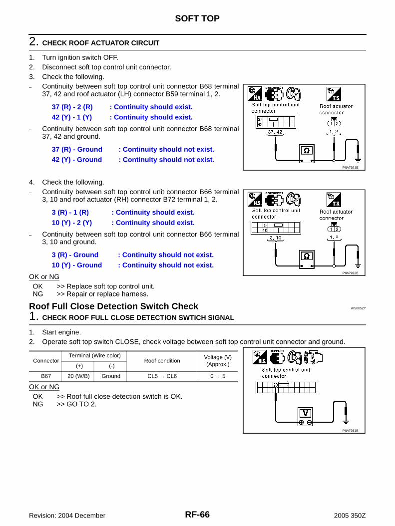
RF-66
SOFT TOP
Revision: 2004 December 2005 350Z
2. CHECK ROOF ACTUATOR CIRCUIT
1. Turn ignition switch OFF.2. Disconnect soft top control unit connector.3. Check the following.– Continuity between soft top control unit connector B68 terminal
37, 42 and roof actuator (LH) connector B59 terminal 1, 2.
– Continuity between soft top control unit connector B68 terminal37, 42 and ground.
4. Check the following.– Continuity between soft top control unit connector B66 terminal
3, 10 and roof actuator (RH) connector B72 terminal 1, 2.
– Continuity between soft top control unit connector B66 terminal3, 10 and ground.
OK or NGOK >> Replace soft top control unit.NG >> Repair or replace harness.
Roof Full Close Detection Switch Check AIS005ZY
1. CHECK ROOF FULL CLOSE DETECTION SWTICH SIGNAL
1. Start engine.2. Operate soft top switch CLOSE, check voltage between soft top control unit connector and ground.
OK or NGOK >> Roof full close detection switch is OK.NG >> GO TO 2.
37 (R) - 2 (R) : Continuity should exist.42 (Y) - 1 (Y) : Continuity should exist.
37 (R) - Ground : Continuity should not exist.42 (Y) - Ground : Continuity should not exist.
PIIA7921E
3 (R) - 1 (R) : Continuity should exist.10 (Y) - 2 (Y) : Continuity should exist.
3 (R) - Ground : Continuity should not exist.10 (Y) - Ground : Continuity should not exist.
PIIA7922E
ConnectorTerminal (Wire color)
Roof conditionVoltage (V)(Approx.) (+) (-)
B67 20 (W/B) Ground CL5 → CL6 0 → 5
PIIA7931E

SOFT TOP
RF-67
C
D
E
F
G
H
J
K
L
M
A
B
RF
Revision: 2004 December 2005 350Z
2. CHECK ROOF FULL CLOSE DETECTION SWITCH CIRCUIT
1. Turn ignition switch OFF.2. Disconnect soft top control unit and soft top switch assembly 2 (roof full close detection switch) connector.3. Check continuity between soft top control unit connector B67
terminal 20 and soft top switch assembly 2 connector B213 ter-minal 2.
4. Check continuity between soft top control unit connector B67terminal 20 and ground.
OK or NGOK >> GO TO 3.NG >> Repair or replace harness.
3. CHECK ROOF FULL CLOSE DETECTION SWITCH GROUND CIRCUIT
Check continuity between soft top switch assembly 2 connector B213 terminal 1 and ground.
OK or NGOK >> GO TO 4.NG >> Repair or replace harness.
4. CHECK SOFT TOP CONTROL UNIT OUTPUT SIGNAL
1. Connect soft top control unit connector.2. Start engine.3. Check voltage between soft top control unit connector B67 ter-
minal 20 and ground.
OK or NGOK >> Replace soft top switch assembly 2.NG >> Replace soft top control unit.
20 (W/B) - 2 (W/G) : Continuity should exist.
20 (W/B) - Ground : Continuity should not exist.
PIIA7932E
1 (B) - Ground : Continuity should exist.
PIIA7925E
20 (W/B) - Ground : Approx. 5V
PIIA7931E
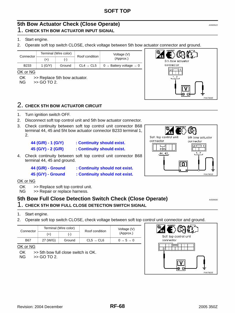
RF-68
SOFT TOP
Revision: 2004 December 2005 350Z
5th Bow Actuator Check (Close Operate) AIS005ZZ
1. CHECK 5TH BOW ACTUATOR INPUT SIGNAL
1. Start engine.2. Operate soft top switch CLOSE, check voltage between 5th bow actuator connector and ground.
OK or NGOK >> Replace 5th bow actuator.NG >> GO TO 2.
2. CHECK 5TH BOW ACTUATOR CIRCUIT
1. Turn ignition switch OFF.2. Disconnect soft top control unit and 5th bow actuator connector.3. Check continuity between soft top control unit connector B68
terminal 44, 45 and 5ht bow actuator connector B233 terminal 1,2.
4. Check continuity between soft top control unit connector B68terminal 44, 45 and ground.
OK or NGOK >> Replace soft top control unit.NG >> Repair or replace harness.
5th Bow Full Close Detection Switch Check (Close Operate) AIS00600
1. CHECK 5TH BOW FULL CLOSE DETECTION SWITCH SIGNAL
1. Start engine.2. Operate soft top switch CLOSE, check voltage between soft top control unit connector and ground.
OK or NGOK >> 5th bow full close switch is OK.NG >> GO TO 2.
ConnectorTerminal (Wire color)
Roof conditionVoltage (V)(Approx.)(+) (-)
B233 1 (G/Y) Ground CL4 → CL5 0 → Battery voltage → 0
PIIA7900E
44 (G/R) - 1 (G/Y) : Continuity should exist.45 (G/Y) - 2 (G/R) : Continuity should exist.
44 (G/R) - Ground : Continuity should not exist.45 (G/Y) - Ground : Continuity should not exist. PIIA7901E
ConnectorTerminal (Wire color)
Roof conditionVoltage (V)(Approx.)(+) (-)
B67 27 (W/G) Ground CL5 → CL6 0 → 5 → 0
PIIA7902E

SOFT TOP
RF-69
C
D
E
F
G
H
J
K
L
M
A
B
RF
Revision: 2004 December 2005 350Z
2. CHECK 5TH BOW FULL CLOSE DETECTION SWITCH CIRCUIT
1. Turn ignition switch OFF.2. Disconnect soft top control unit and 5th bow switch assembly (at plate rail RR) connector.3. Check continuity between soft top control unit connector B67
terminal 27 and 5th bow switch assembly connector B214 termi-nal 2.
4. Check continuity between soft top control unit connector B67terminal 27 and ground.
OK or NGOK >> GO TO 3.NG >> Repair or replace harness.
3. CHECK 5TH BOW FULL CLOSE DETECTION SWITCH GROUND CIRCUIT
Check continuity between 5th bow switch assembly connector B214 terminal 3 and ground.
OK or NGOK >> GO TO 4.NG >> Repair or replace harness.
4. CHECK SOFT TOP CONTORL UNIT OUTPUT SIGNAL
1. Connect soft top control unit connector.2. Start engine.3. Check voltage between soft top control unit connector B67 ter-
minal 27 and ground.
OK or NGOK >> Replace plate rail RR.NG >> Replace soft top control unit.
27 (W/G) - 2 (W/G) : Continuity should exist.
27 (W/G) - Ground : Continuity should not exist.
PIIA7903E
3 (B) - Ground : Continuity should exist.
PIIA7904E
27 (W/G) - Ground : Approx. 5V
PIIA7902E

RF-70
SOFT TOP
Revision: 2004 December 2005 350Z
5th Bow Full Open Detection Switch Check (Close Operate) AIS00601
1. CHECK 5TH BOW FULL OPEN DETECTION SWTICH SIGNAL
1. Start engine.2. Operate soft top switch CLOSE, check voltage between soft top control unit connector and ground.
OK or NGOK >> 5th bow full open switch is OK.NG >> GO TO 2.
2. CHECK 5TH BOW FULL OPEN DETECTION SWITCH CIRCUIT
1. Turn ignition switch OFF.2. Disconnect soft top control unit and 5th bow switch assembly connector.3. Check continuity between soft top control unit connector B67
terminal 26 and 5th bow switch assembly connector B214 termi-nal 1.
4. Check continuity between soft top control unit connector B67terminal 26 and ground.
OK or NGOK >> GO TO 3.NG >> Repair or replace harness.
3. CHECK 5TH BOW FULL OPEN DETECTION SWITCH GROUND CIRCUIT
Check continuity between 5th bow switch assembly connector B214 terminal 3 and ground.
OK or NGOK >> GO TO 4.NG >> Repair or replace harness.
ConnectorTerminal (Wire color)
Roof conditionVoltage (V)(Approx.)(+) (-)
B67 26 (LG) Ground CL6 → CL7 5 → 0
PIIA7905E
26 (LG) - 1 (LG) : Continuity should exist.
26 (LG) - Ground : Continuity should not exist.
PIIA7906E
3 (B) - Ground : Continuity should exist.
PIIA7904E

SOFT TOP
RF-71
C
D
E
F
G
H
J
K
L
M
A
B
RF
Revision: 2004 December 2005 350Z
4. CHECK SOFT TOP CONTORL UNIT OUTPUT SIGNAL
1. Connect soft top control unit connector.2. Start engine.3. Check voltage between soft top control unit connector B67 ter-
minal 26 and ground.
OK or NGOK >> Replace plate rail RR.NG >> Replace soft top control unit.
5th Bow Half-Latch Switch Check (Close Operate) AIS00602
1. CHECK 5TH BOW HALF-LATCH SWITCH SIGNAL CHECK
1. Start engine.2. Operate soft top switch CLOSE, check voltage between soft top control unit connector and ground.
OK or NGOK >> 5th bow half-latch switch is OK.NG >> GO TO 2.
2. CHECK 5TH BOW HALF-LATCH CIRCUIT
1. Turn ignition switch OFF.2. Disconnect soft top control unit and soft top lock switch (at 5th bow lock assembly in storage lid) connec-
tor.3. Check continuity between soft top control unit connector B67
terminal 31 and soft top lock switch connector T205 terminal 5.
4. Check continuity between soft top control unit connector B67terminal 31 and ground.
OK or NGOK >> GO TO 3.NG >> Repair or replace harness.
26 (LG) - Ground : Approx. 5V
PIIA7905E
ConnectorTerminal (Wire color)
Roof conditionVoltage (V)(Approx.)(+) (-)
B67 31 (L) Ground CL9 → CL10 0 → 5
PIIA7897E
31 (L) - 5 (L) : Continuity should exist.
31 (L) - Ground : Continuity should not exist.
PIIA7898E
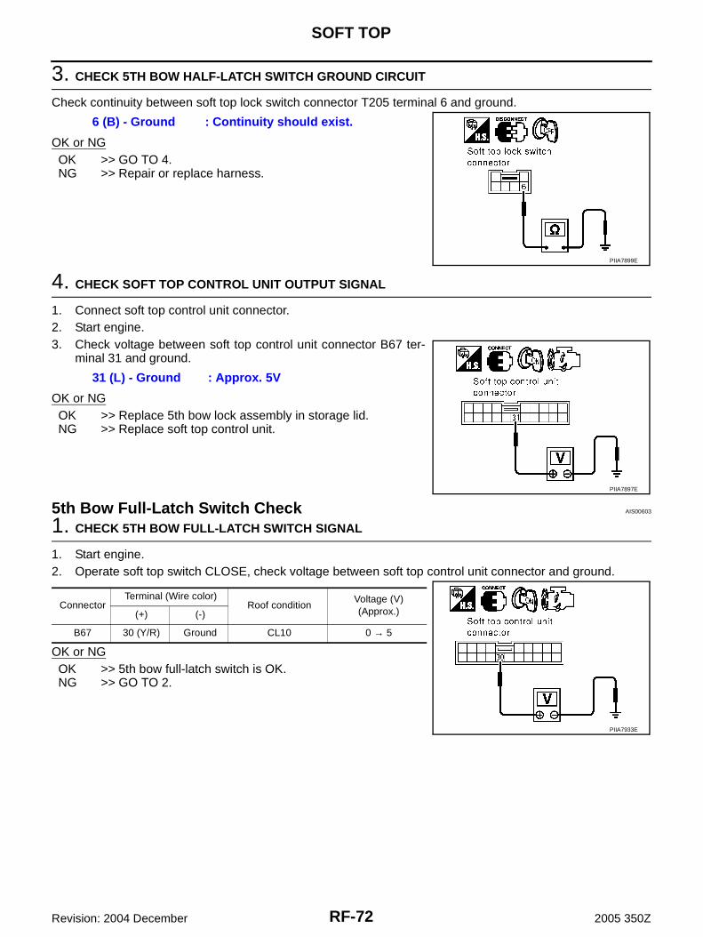
RF-72
SOFT TOP
Revision: 2004 December 2005 350Z
3. CHECK 5TH BOW HALF-LATCH SWITCH GROUND CIRCUIT
Check continuity between soft top lock switch connector T205 terminal 6 and ground.
OK or NGOK >> GO TO 4. NG >> Repair or replace harness.
4. CHECK SOFT TOP CONTROL UNIT OUTPUT SIGNAL
1. Connect soft top control unit connector.2. Start engine.3. Check voltage between soft top control unit connector B67 ter-
minal 31 and ground.
OK or NGOK >> Replace 5th bow lock assembly in storage lid.NG >> Replace soft top control unit.
5th Bow Full-Latch Switch Check AIS00603
1. CHECK 5TH BOW FULL-LATCH SWITCH SIGNAL
1. Start engine.2. Operate soft top switch CLOSE, check voltage between soft top control unit connector and ground.
OK or NGOK >> 5th bow full-latch switch is OK.NG >> GO TO 2.
6 (B) - Ground : Continuity should exist.
PIIA7899E
31 (L) - Ground : Approx. 5V
PIIA7897E
ConnectorTerminal (Wire color)
Roof conditionVoltage (V)(Approx.)(+) (-)
B67 30 (Y/R) Ground CL10 0 → 5
PIIA7933E

SOFT TOP
RF-73
C
D
E
F
G
H
J
K
L
M
A
B
RF
Revision: 2004 December 2005 350Z
2. CHECK 5TH BOW FULL-LATCH CIRCUIT
1. Turn ignition switch OFF.2. Disconnect soft top control unit and soft top lock switch (at 5th bow lock assembly in storage lid) connec-
tor.3. Check continuity between soft top control unit connector B67
terminal 30 and soft top lock switch connector T205 terminal 3.
4. Check continuity between soft top control unit connector B67terminal 30 and ground.
OK or NGOK >> GO TO 3.NG >> Repair or replace harness.
3. CHECK 5TH BOW HALF-LATCH SWITCH GROUND CIRCUIT
Check continuity between soft top lock switch connector T205 terminal 4 and ground.
OK or NGOK >> GO TO 4. NG >> Repair or replace harness.
4. CHECK SOFT TOP CONTROL UNIT OUTPUT SIGNAL
1. Connect soft top control unit connector.2. Start engine.3. Check voltage between soft top control unit connector B67 ter-
minal 30 and ground.
OK or NGOK >> Replace 5th bow assembly in storage lid.NG >> Replace soft top control unit.
30 (Y/R) - 3 (Y) : Continuity should exist.
30 (Y/R) - Ground : Continuity should not exist.
PIIA7934E
4 (B) - Ground : Continuity should exist.
PIIA7935E
30 (Y/R) - Ground : Approx. 5V
PIIA7933E
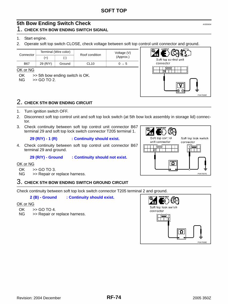
RF-74
SOFT TOP
Revision: 2004 December 2005 350Z
5th Bow Ending Switch Check AIS00604
1. CHECK 5TH BOW ENDING SWITCH SIGNAL
1. Start engine.2. Operate soft top switch CLOSE, check voltage between soft top control unit connector and ground.
OK or NGOK >> 5th bow ending switch is OK.NG >> GO TO 2.
2. CHECK 5TH BOW ENDING CIRCUIT
1. Turn ignition switch OFF.2. Disconnect soft top control unit and soft top lock switch (at 5th bow lock assembly in storage lid) connec-
tor.3. Check continuity between soft top control unit connector B67
terminal 29 and soft top lock switch connector T205 terminal 1.
4. Check continuity between soft top control unit connector B67terminal 29 and ground.
OK or NGOK >> GO TO 3.NG >> Repair or replace harness.
3. CHECK 5TH BOW ENDING SWITCH GROUND CIRCUIT
Check continuity between soft top lock switch connector T205 terminal 2 and ground.
OK or NGOK >> GO TO 4. NG >> Repair or replace harness.
ConnectorTerminal (Wire color)
Roof conditionVoltage (V)(Approx.)(+) (-)
B67 29 (R/Y) Ground CL10 0 → 5
PIIA7936E
29 (R/Y) - 1 (R) : Continuity should exist.
29 (R/Y) - Ground : Continuity should not exist.
PIIA7937E
2 (B) - Ground : Continuity should exist.
PIIA7938E

SOFT TOP
RF-75
C
D
E
F
G
H
J
K
L
M
A
B
RF
Revision: 2004 December 2005 350Z
4. CHECK SOFT TOP CONTROL UNIT OUTPUT SIGNAL
1. Connect soft top control unit connector.2. Start engine.3. Check voltage between soft top control unit connector B67 ter-
minal 29 and ground.
OK or NGOK >> Replace 5th bow lock assembly in storage lid.NG >> Replace soft top control unit.
5th Bow Closure Motor Check AIS00605
1. 5TH BOW CLOSURE MOTOR INPUT SIGNAL
1. Start engine.2. Operate soft top switch CLOSE, check voltage between 5th bow closure motor connector and ground.
OK or NGOK >> Replace 5th bow closure motor.NG >> GO TO 2.
2. CHECK 5TH BOW CLOSURE MOTOR CIRCUIT
1. Turn ignition switch OFF.2. Disconnect soft top control unit and 5th bow closure motor connector.3. Check continuity between soft top control unit connector B66
terminal 4, 12 and 5th bow closure motor connector T204 termi-nal 1, 2.
4. Check continuity between soft top control unit connector B66terminal 4, 12 and ground.
OK or NGOK >> Replace soft top control unit.NG >> Repair or replace harness.
29 (R/Y) - Ground : Approx. 5V
PIIA7936E
ConnectorTerminal (Wire color)
Roof conditionVoltage (V)(Approx.)(+) (-)
T204 1 (W) Ground CL9 → CL10 0 → Battery voltage → 0
PIIA7939E
4 (G/W) - 1 (W) : Continuity should exist.12 (G/Y) - 2 (G) : Continuity should exist.
4 (G/W) - Ground : Continuity should not exist.12 (G/Y) - Ground : Continuity should not exist. PIIA7940E
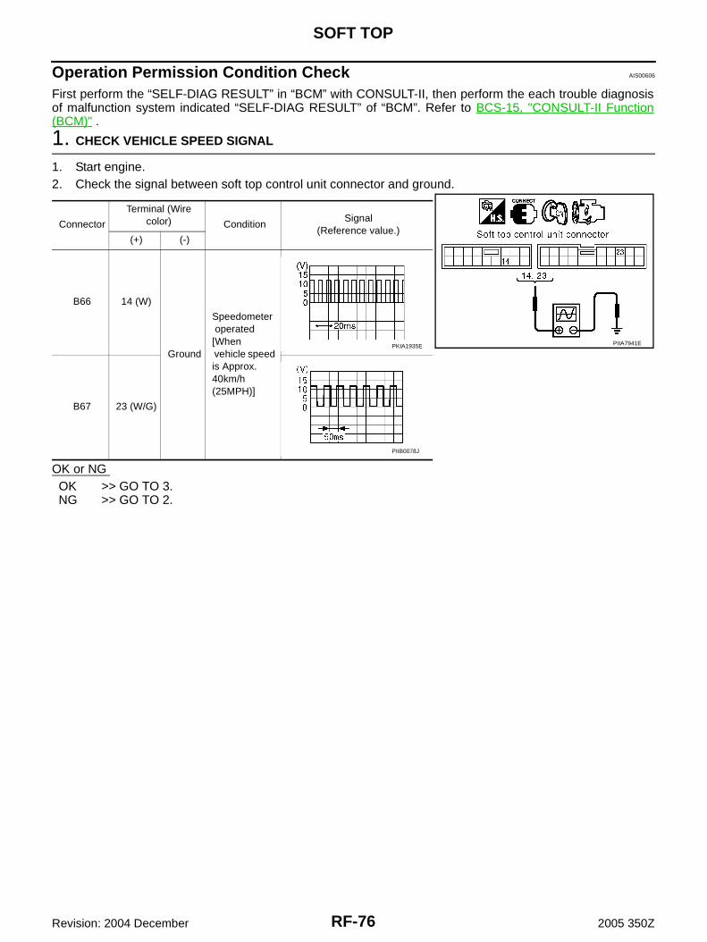
RF-76
SOFT TOP
Revision: 2004 December 2005 350Z
Operation Permission Condition Check AIS00606
First perform the “SELF-DIAG RESULT” in “BCM” with CONSULT-II, then perform the each trouble diagnosisof malfunction system indicated “SELF-DIAG RESULT” of “BCM”. Refer to BCS-15, "CONSULT-II Function(BCM)" .
1. CHECK VEHICLE SPEED SIGNAL
1. Start engine.2. Check the signal between soft top control unit connector and ground.
OK or NG OK >> GO TO 3.NG >> GO TO 2.
Connector
Terminal (Wire color) Condition
Signal(Reference value.)
(+) (-)
B66 14 (W)
Ground
Speedometer operated [When vehicle speed is Approx. 40km/h (25MPH)]
B67 23 (W/G)
PIIA7941EPKIA1935E
PIIB0078J
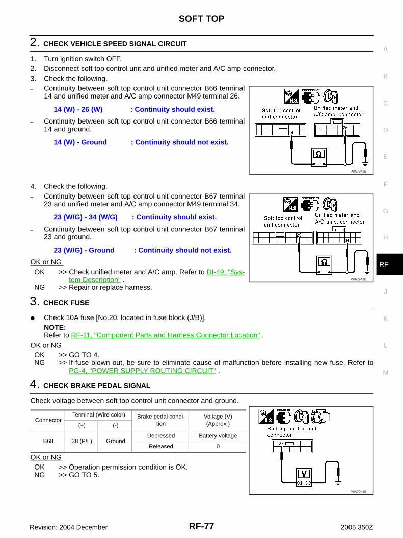
SOFT TOP
RF-77
C
D
E
F
G
H
J
K
L
M
A
B
RF
Revision: 2004 December 2005 350Z
2. CHECK VEHICLE SPEED SIGNAL CIRCUIT
1. Turn ignition switch OFF.2. Disconnect soft top control unit and unified meter and A/C amp connector.3. Check the following.– Continuity between soft top control unit connector B66 terminal
14 and unified meter and A/C amp connector M49 terminal 26.
– Continuity between soft top control unit connector B66 terminal14 and ground.
4. Check the following.– Continuity between soft top control unit connector B67 terminal
23 and unified meter and A/C amp connector M49 terminal 34.
– Continuity between soft top control unit connector B67 terminal23 and ground.
OK or NG OK >> Check unified meter and A/C amp. Refer to DI-49, "Sys-
tem Description" .NG >> Repair or replace harness.
3. CHECK FUSE
● Check 10A fuse [No.20, located in fuse block (J/B)].NOTE:Refer to RF-11, "Component Parts and Harness Connector Location" .
OK or NGOK >> GO TO 4.NG >> If fuse blown out, be sure to eliminate cause of malfunction before installing new fuse. Refer to
PG-4, "POWER SUPPLY ROUTING CIRCUIT" .
4. CHECK BRAKE PEDAL SIGNAL
Check voltage between soft top control unit connector and ground.
OK or NGOK >> Operation permission condition is OK.NG >> GO TO 5.
14 (W) - 26 (W) : Continuity should exist.
14 (W) - Ground : Continuity should not exist.
PIIA7942E
23 (W/G) - 34 (W/G) : Continuity should exist.
23 (W/G) - Ground : Continuity should not exist.
PIIA7943E
ConnectorTerminal (Wire color) Brake pedal condi-
tionVoltage (V)(Approx.)(+) (-)
B68 38 (P/L) GroundDepressed Battery voltage
Released 0
PIIA7944E

RF-78
SOFT TOP
Revision: 2004 December 2005 350Z
5. CHECK BRAKE PEDAL SIGNAL CIRCUIT
1. Turn ignition switch OFF.2. Disconnect soft top control unit and stop lamp switch connector.3. Check the following.(M/T Models)– Continuity between soft top control unit connector B68 terminal
38 and stop lamp switch connector E112 terminal 2.
– Continuity between soft top control unit connector B68 terminal38 and ground.
(A/T Models)– Continuity between soft top control unit connector B68 terminal
38 and stop lamp switch connector E111 terminal 2.
– Continuity between soft top control unit connector B68 terminal38 and ground.
OK or NG OK >> GO TO 6.NG >> Repair or replace harness.
38 (P/L) - 2 (P/L) : Continuity should exist.
38 (P/L) - Ground : Continuity should not exist.
PIIA7945E
38 (P/L) - 2 (P/L) : Continuity should exist.
38 (P/L) - Ground : Continuity should not exist.
PIIA7946E
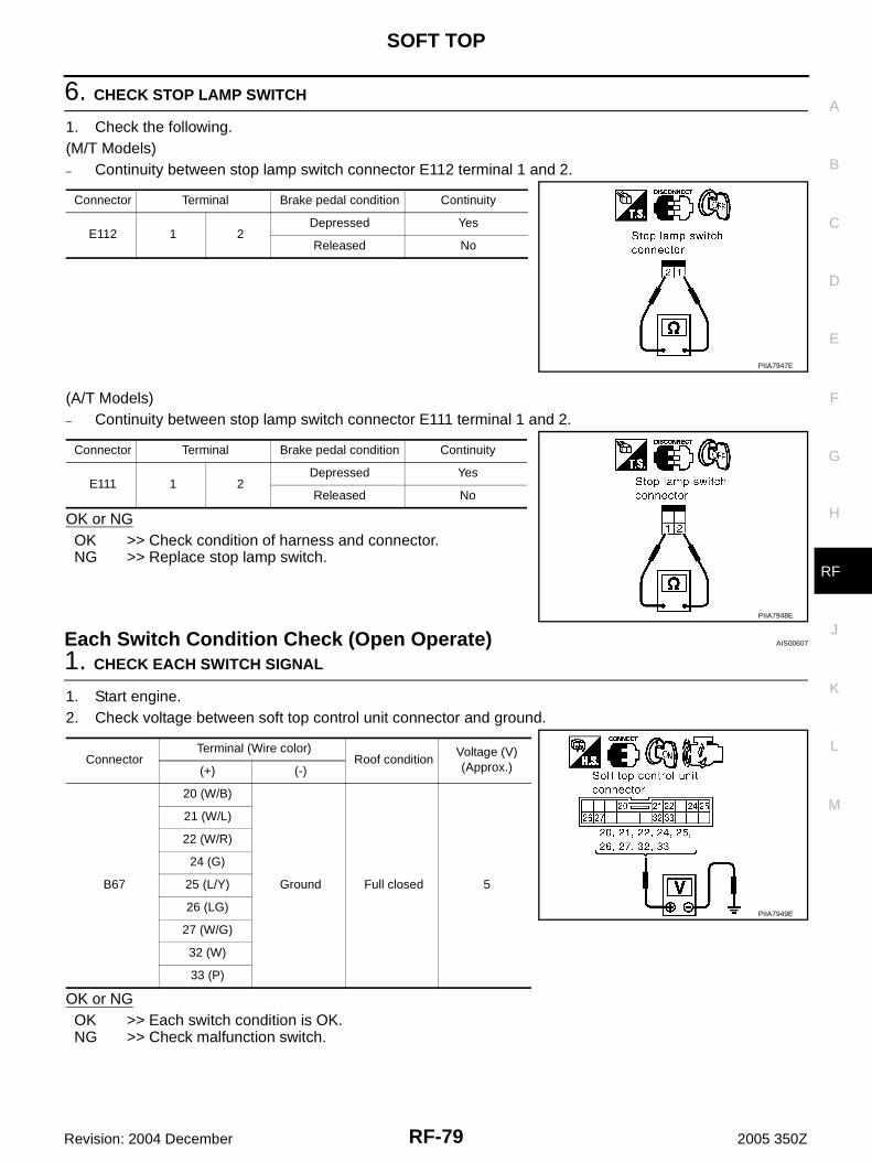
SOFT TOP
RF-79
C
D
E
F
G
H
J
K
L
M
A
B
RF
Revision: 2004 December 2005 350Z
6. CHECK STOP LAMP SWITCH
1. Check the following.(M/T Models)– Continuity between stop lamp switch connector E112 terminal 1 and 2.
(A/T Models)– Continuity between stop lamp switch connector E111 terminal 1 and 2.
OK or NGOK >> Check condition of harness and connector.NG >> Replace stop lamp switch.
Each Switch Condition Check (Open Operate) AIS00607
1. CHECK EACH SWITCH SIGNAL
1. Start engine.2. Check voltage between soft top control unit connector and ground.
OK or NGOK >> Each switch condition is OK.NG >> Check malfunction switch.
Connector Terminal Brake pedal condition Continuity
E112 1 2Depressed Yes
Released No
PIIA7947E
Connector Terminal Brake pedal condition Continuity
E111 1 2Depressed Yes
Released No
PIIA7948E
ConnectorTerminal (Wire color)
Roof conditionVoltage (V)(Approx.)(+) (-)
B67
20 (W/B)
Ground Full closed 5
21 (W/L)
22 (W/R)
24 (G)
25 (L/Y)
26 (LG)
27 (W/G)
32 (W)
33 (P)
PIIA7949E
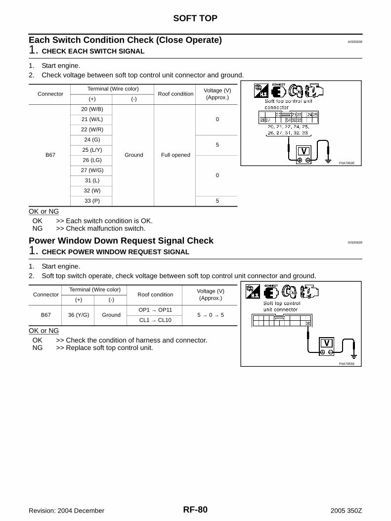
RF-80
SOFT TOP
Revision: 2004 December 2005 350Z
Each Switch Condition Check (Close Operate) AIS00608
1. CHECK EACH SWITCH SIGNAL
1. Start engine.2. Check voltage between soft top control unit connector and ground.
OK or NGOK >> Each switch condition is OK.NG >> Check malfunction switch.
Power Window Down Request Signal Check AIS00609
1. CHECK POWER WINDOW REQUEST SIGNAL
1. Start engine.2. Soft top switch operate, check voltage between soft top control unit connector and ground.
OK or NGOK >> Check the condition of harness and connector.NG >> Replace soft top control unit.
ConnectorTerminal (Wire color)
Roof conditionVoltage (V)(Approx.)(+) (-)
B67
20 (W/B)
Ground Full opened
021 (W/L)
22 (W/R)
24 (G)5
25 (L/Y)
26 (LG)
027 (W/G)
31 (L)
32 (W)
33 (P) 5
PIIA7950E
ConnectorTerminal (Wire color)
Roof conditionVoltage (V)(Approx.)(+) (-)
B67 36 (Y/G) GroundOP1 → OP11
5 → 0 → 5CL1 → CL10
PIIA7955E
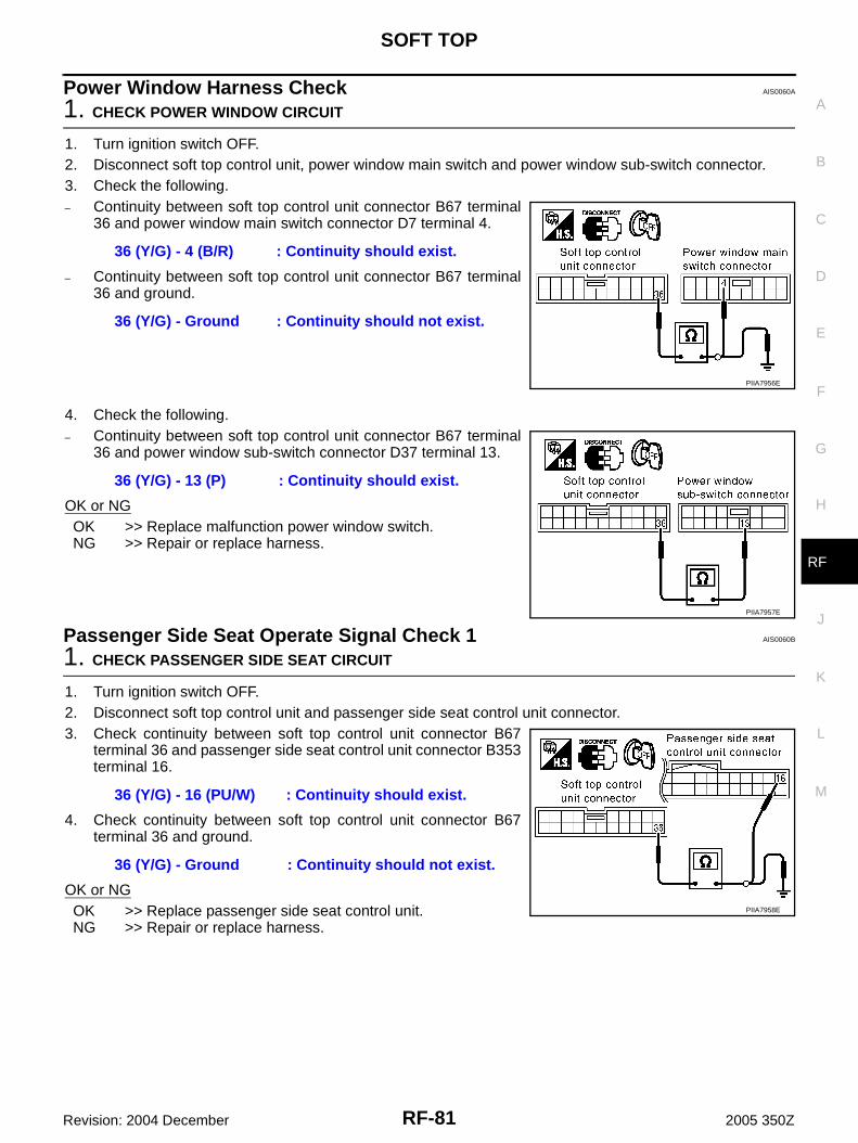
SOFT TOP
RF-81
C
D
E
F
G
H
J
K
L
M
A
B
RF
Revision: 2004 December 2005 350Z
Power Window Harness Check AIS0060A
1. CHECK POWER WINDOW CIRCUIT
1. Turn ignition switch OFF.2. Disconnect soft top control unit, power window main switch and power window sub-switch connector.3. Check the following.– Continuity between soft top control unit connector B67 terminal
36 and power window main switch connector D7 terminal 4.
– Continuity between soft top control unit connector B67 terminal36 and ground.
4. Check the following.– Continuity between soft top control unit connector B67 terminal
36 and power window sub-switch connector D37 terminal 13.
OK or NGOK >> Replace malfunction power window switch.NG >> Repair or replace harness.
Passenger Side Seat Operate Signal Check 1 AIS0060B
1. CHECK PASSENGER SIDE SEAT CIRCUIT
1. Turn ignition switch OFF.2. Disconnect soft top control unit and passenger side seat control unit connector.3. Check continuity between soft top control unit connector B67
terminal 36 and passenger side seat control unit connector B353terminal 16.
4. Check continuity between soft top control unit connector B67terminal 36 and ground.
OK or NGOK >> Replace passenger side seat control unit.NG >> Repair or replace harness.
36 (Y/G) - 4 (B/R) : Continuity should exist.
36 (Y/G) - Ground : Continuity should not exist.
PIIA7956E
36 (Y/G) - 13 (P) : Continuity should exist.
PIIA7957E
36 (Y/G) - 16 (PU/W) : Continuity should exist.
36 (Y/G) - Ground : Continuity should not exist.
PIIA7958E
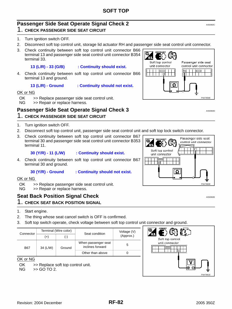
RF-82
SOFT TOP
Revision: 2004 December 2005 350Z
Passenger Side Seat Operate Signal Check 2 AIS0060C
1. CHECK PASSENGER SIDE SEAT CIRCUIT
1. Turn ignition switch OFF.2. Disconnect soft top control unit, storage lid actuator RH and passenger side seat control unit connector.3. Check continuity between soft top control unit connector B66
terminal 13 and passenger side seat control unit connector B354terminal 33.
4. Check continuity between soft top control unit connector B66terminal 13 and ground.
OK or NGOK >> Replace passenger side seat control unit.NG >> Repair or replace harness.
Passenger Side Seat Operate Signal Check 3 AIS0060D
1. CHECK PASSENGER SIDE SEAT CIRCUIT
1. Turn ignition switch OFF.2. Disconnect soft top control unit, passenger side seat control unit and soft top lock switch connector.3. Check continuity between soft top control unit connector B67
terminal 30 and passenger side seat control unit connector B353terminal 11.
4. Check continuity between soft top control unit connector B67terminal 30 and ground.
OK or NG OK >> Replace passenger side seat control unit.NG >> Repair or replace harness.
Seat Back Position Signal Check AIS0060E
1. CHECK SEAT BACK POSITION SIGNAL
1. Start engine.2. The thing whose seat cancel switch is OFF is confirmed.3. Soft top switch operate, check voltage between soft top control unit connector and ground.
OK or NGOK >> Replace soft top control unit.NG >> GO TO 2.
13 (L/R) - 33 (G/B) : Continuity should exist.
13 (L/R) - Ground : Continuity should not exist.
PIIA7959E
30 (Y/R) - 11 (L/W) : Continuity should exist.
30 (Y/R) - Ground : Continuity should not exist.
PIIA7960E
ConnectorTerminal (Wire color)
Seat conditionVoltage (V)(Approx.)(+) (-)
B67 34 (L/W) Ground
When passenger seat inclines forward
5
Other than above 0
PIIA7961E

SOFT TOP
RF-83
C
D
E
F
G
H
J
K
L
M
A
B
RF
Revision: 2004 December 2005 350Z
2. CHECK SEAT BACK POSITION SIGNAL CIRCUIT
1. Turn ignition switch OFF.2. Disconnect soft top control unit and passenger side seat control unit connector.3. Check continuity between soft top control unit connector B67
terminal 34 and passenger side seat control unit connector B353terminal 32.
4. Check continuity between soft top control unit connector B67terminal 34 and ground.
OK or NGOK >> Check passenger side seat. Refer to SE-36, "Trouble
Diagnosis Symptom Chart" .NG >> Repair or replace harness.
Speed Signal Circuit Check AIS0060F
First perform the “SELF-DIAG RESULT” in “BCM” with CONSULT-II, then perform the each trouble diagnosisof malfunction system indicated “SELF-DIAG RESULT” of “BCM”. Refer to BCS-15, "CONSULT-II Function(BCM)" .
1. CHECK VEHICLE SPEED SIGNAL
1. Start engine.2. Check the signal between soft top control unit connector and ground.
OK or NG OK >> Replace soft top control unit.NG >> GO TO 2.
34 (L/W) - 32 (G/W) : Continuity should exist.
34 (L/W) - Ground : Continuity should not exist.
PIIA7962E
Connector
Terminal (Wire color) Condition
Signal(Reference value.)
(+) (-)
B66 14 (W)
Ground
Speedometer operated [When vehicle speed is Approx. 40km/h (25MPH)]
B67 23 (W/G)
PIIA7941EPKIA1935E
PIIB0078J
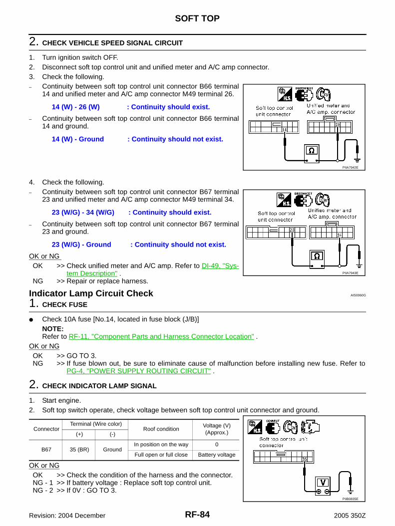
RF-84
SOFT TOP
Revision: 2004 December 2005 350Z
2. CHECK VEHICLE SPEED SIGNAL CIRCUIT
1. Turn ignition switch OFF.2. Disconnect soft top control unit and unified meter and A/C amp connector.3. Check the following.– Continuity between soft top control unit connector B66 terminal
14 and unified meter and A/C amp connector M49 terminal 26.
– Continuity between soft top control unit connector B66 terminal14 and ground.
4. Check the following.– Continuity between soft top control unit connector B67 terminal
23 and unified meter and A/C amp connector M49 terminal 34.
– Continuity between soft top control unit connector B67 terminal23 and ground.
OK or NG OK >> Check unified meter and A/C amp. Refer to DI-49, "Sys-
tem Description" .NG >> Repair or replace harness.
Indicator Lamp Circuit Check AIS0060G
1. CHECK FUSE
● Check 10A fuse [No.14, located in fuse block (J/B)]NOTE:Refer to RF-11, "Component Parts and Harness Connector Location" .
OK or NGOK >> GO TO 3.NG >> If fuse blown out, be sure to eliminate cause of malfunction before installing new fuse. Refer to
PG-4, "POWER SUPPLY ROUTING CIRCUIT" .
2. CHECK INDICATOR LAMP SIGNAL
1. Start engine.2. Soft top switch operate, check voltage between soft top control unit connector and ground.
OK or NGOK >> Check the condition of the harness and the connector.NG - 1 >> If battery voltage : Replace soft top control unit.NG - 2 >> If 0V : GO TO 3.
14 (W) - 26 (W) : Continuity should exist.
14 (W) - Ground : Continuity should not exist.
PIIA7942E
23 (W/G) - 34 (W/G) : Continuity should exist.
23 (W/G) - Ground : Continuity should not exist.
PIIA7943E
ConnectorTerminal (Wire color)
Roof conditionVoltage (V)(Approx.)(+) (-)
B67 35 (BR) GroundIn position on the way 0
Full open or full close Battery voltage
PIIB0835E

SOFT TOP
RF-85
C
D
E
F
G
H
J
K
L
M
A
B
RF
Revision: 2004 December 2005 350Z
3. CHECK INDICATOR LAMP CIRCUIT
1. Turn ignition switch OFF.2. Disconnect soft top control unit and combination meter connector.3. Check continuity between soft top control unit connector B67
terminal 35 and combination meter connector M19 terminal 13.
4. Check continuity between soft top control unit connector B67terminal 35 and ground.
OK or NGOK >> GO TO 4.NG >> Repair or replace harness.
4. CHECK INDICATOR LAMP POWER SUPPLY
1. Turn ignition switch ON.2. Check voltage between combination meter connector M19 ter-
minal 23 and ground.
OK or NGOK >> Check the Condition of the Harness and the Connector.
● If OK : Replace combination meter.● If NG : Repair or replace harness.
NG >> Repair or replace harness.
Removal and Installation of Soft Top Control Unit AIS0060H
REMOVAL1. Push the soft top switch on the close side to clear the soft top strage room, and release the buttom before
strage lid starts closing.2. Remove trim parts and turn the front side of storage room finisher. RF-125, "Removal and Installation of
Storage Room Finisher"3. Disconnect soft top control unit connector, remove the screw
and soft top control unit.
INSTALLATIONInstallation in the reverse order of removal.
35 (BR) – 13 (G/W) : Continuity should exist.
35 (BR) – Ground : Continuity should not exist.
PIIB0836E
23 (G/Y) – Ground : Battery voltage
PIIB0837E
PIIB0838E

RF-86
SOFT TOP
Revision: 2004 December 2005 350Z
Component Parts Drawing AIS0060I
PIIB1399E
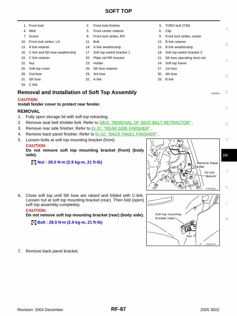
SOFT TOP
RF-87
C
D
E
F
G
H
J
K
L
M
A
B
RF
Revision: 2004 December 2005 350Z
Removal and Installation of Soft Top Assembly AIS0060J
CAUTION:Install fender cover to protect rear fender.
REMOVAL1. Fully open storage lid with soft top retracting.2. Remove seat belt sholder bolt. Refer to SB-6, "REMOVAL OF SEAT BELT RETRACTOR" .3. Remove rear side finisher. Refer to EI-37, "REAR SIDE FINISHER" .4. Remove back panel finisher. Refer to EI-42, "BACK PANEL FINISHER" .5. Loosen bolts at soft top mounting bracket (front).
CAUTION:Do not remove soft top mounting bracket (front) (bodyside).
6. Close soft top until 5th bow are raised and folded with C-link.Loosen nut at soft top mounting bracket (rear). Then fold (open)soft top assembly completely.CAUTION:Do not remove soft top mounting bracket (rear) (body side).
7. Remove back panel bracket.
1. Front lock 2. Front lock finisher 3. TORX bolt (T30)
4. Welt 5. Front center retainer 6. Clip
7. Screw 8. Front lock striker, RH 9. Front lock striker, center
10. Front lock striker, LH 11. Bolt 12. B link retainer
13. A link retainer 14. A link weatherstrip 15. B link weatherstrip
16. C link and 5th bow weatherstrip 17. Soft top switch bracket 1 18. Soft top switch bracket 2
19. C link retainer 20. Plate rail RR bracket 21. 5th bow operating strut rod
22. Nut 23. Holder 24. Soft top frame
25. Soft top cover 26. 5th bow retainer 27. 1st bow
28. 2nd bow 29. 3rd bow 30. 4th bow
31. 5th bow 32. A link 33. B link
34. C link
Nut : 28.0 N·m (2.9 kg-m, 21 ft-lb)
PIIA7824E
Bolt : 28.0 N·m (2.9 kg-m, 21 ft-lb)
PIIA7877E

RF-88
SOFT TOP
Revision: 2004 December 2005 350Z
8. Remove bolts, at the soft top mounting plate and shims.CAUTION:Do not replace left and right shims with each one with dif-ferent thickness.
9. Disconnect harness connector.
10. Lift up soft top assembly from left and right, and then remove soft top assembly
CAUTION:2 workers are required for the heavy load of approximately 40 kg (89 lb).
INSTALLATIONInstall in the reverse order of removal except the order of tightening bolts and nuts. (See note below.)NOTE:● Before tighten soft top fixing bolts and nuts, make sure that soft top is sat on each pins from soft top
mounting brackets without any gaps.To sit soft top correctly, follow this order.
1. Push soft top assembly down when nuts at soft top mounting bracket (rear) is tighten.2. Close soft top until the angle of A-link becomes vertical against ground, then tighten bolts at soft top
mounting bracket (front).3. Tighten bolts at soft top mounting plate with shims, then attach back panel bracket with bolts.
Bolt: 28.0 N·m (2.9 kg-m, 21 ft-lb)
PIIA7863E
PIIA7878E
PIIB1302E
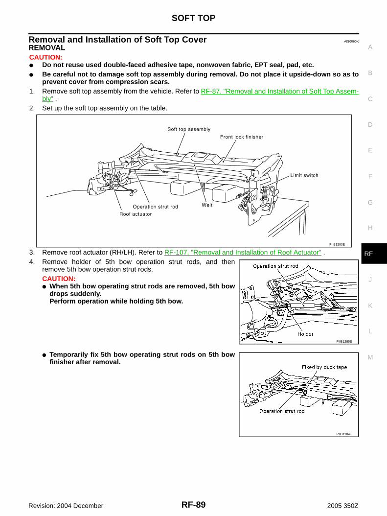
SOFT TOP
RF-89
C
D
E
F
G
H
J
K
L
M
A
B
RF
Revision: 2004 December 2005 350Z
Removal and Installation of Soft Top Cover AIS0060K
REMOVALCAUTION:● Do not reuse used double-faced adhesive tape, nonwoven fabric, EPT seal, pad, etc.● Be careful not to damage soft top assembly during removal. Do not place it upside-down so as to
prevent cover from compression scars.1. Remove soft top assembly from the vehicle. Refer to RF-87, "Removal and Installation of Soft Top Assem-
bly" .2. Set up the soft top assembly on the table.
3. Remove roof actuator (RH/LH). Refer to RF-107, "Removal and Installation of Roof Actuator" .4. Remove holder of 5th bow operation strut rods, and then
remove 5th bow operation strut rods.CAUTION:● When 5th bow operating strut rods are removed, 5th bow
drops suddenly. Perform operation while holding 5th bow.
● Temporarily fix 5th bow operating strut rods on 5th bowfinisher after removal.
PIIB1283E
PIIB1285E
PIIB1284E
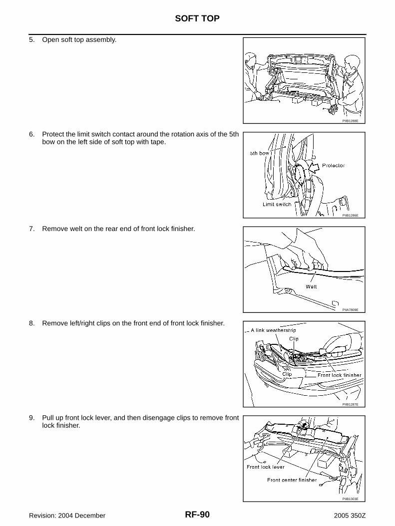
RF-90
SOFT TOP
Revision: 2004 December 2005 350Z
5. Open soft top assembly.
6. Protect the limit switch contact around the rotation axis of the 5thbow on the left side of soft top with tape.
7. Remove welt on the rear end of front lock finisher.
8. Remove left/right clips on the front end of front lock finisher.
9. Pull up front lock lever, and then disengage clips to remove frontlock finisher.
PIIB1288E
PIIB1286E
PIIA7809E
PIIB1287E
PIIB1303E

SOFT TOP
RF-91
C
D
E
F
G
H
J
K
L
M
A
B
RF
Revision: 2004 December 2005 350Z
10. Remove clip, and then A link weatherstrip.
11. Peel a link sealing out.
12. Remove screws, and then remove front center retainer.
13. Put matching marks to installation position of A link retainer.
14. Remove screws, and then remove A link retainer.
PIIB1289E
PIIB1291E
PIIB1290E
PIIB1292E
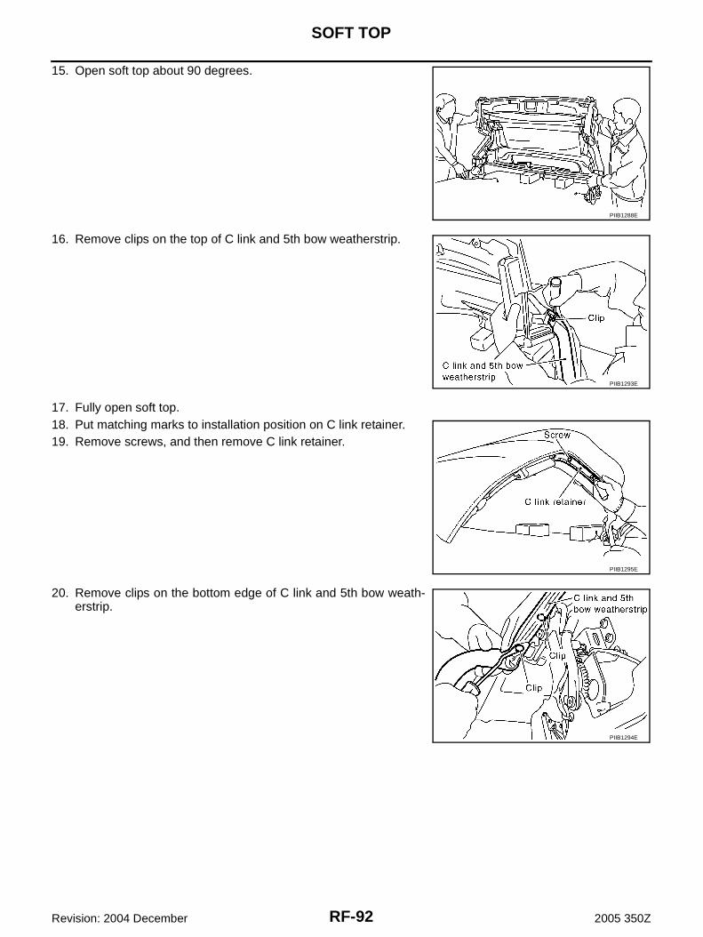
RF-92
SOFT TOP
Revision: 2004 December 2005 350Z
15. Open soft top about 90 degrees.
16. Remove clips on the top of C link and 5th bow weatherstrip.
17. Fully open soft top.18. Put matching marks to installation position on C link retainer.19. Remove screws, and then remove C link retainer.
20. Remove clips on the bottom edge of C link and 5th bow weath-erstrip.
PIIB1288E
PIIB1293E
PIIB1295E
PIIB1294E
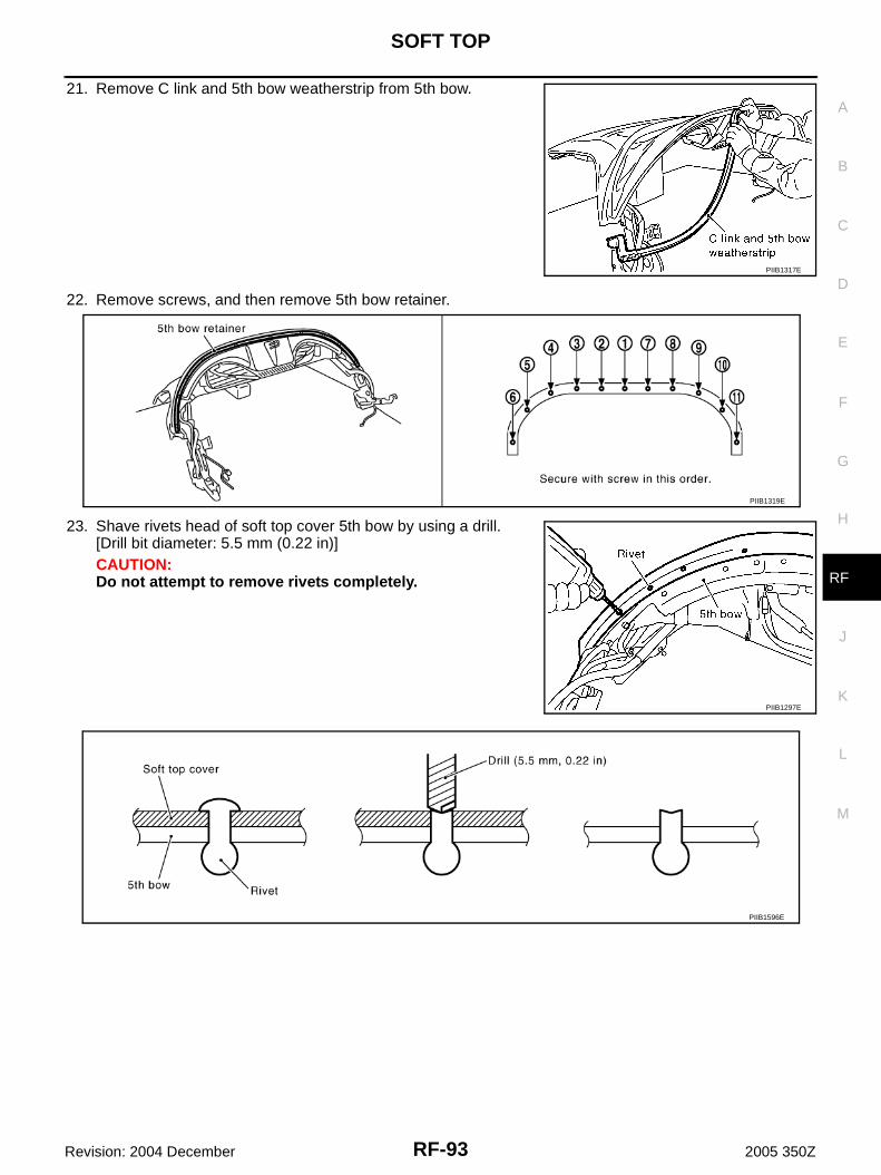
SOFT TOP
RF-93
C
D
E
F
G
H
J
K
L
M
A
B
RF
Revision: 2004 December 2005 350Z
21. Remove C link and 5th bow weatherstrip from 5th bow.
22. Remove screws, and then remove 5th bow retainer.
23. Shave rivets head of soft top cover 5th bow by using a drill.[Drill bit diameter: 5.5 mm (0.22 in)]CAUTION:Do not attempt to remove rivets completely.
PIIB1317E
PIIB1319E
PIIB1297E
PIIB1596E

RF-94
SOFT TOP
Revision: 2004 December 2005 350Z
24. Close soft top, and then Shave rivets head and of C link by usinga drill.[Drill bit diameter: 5.5 mm (0.22 in)]CAUTION:Do not attempt to remove rivets completely.
25. Cut EPT seal and remove screws on the bottom of C link.NOTE:Check the position when cutting EPT seal.
26. Pull up soft top cover from 5th bow finisher.27. Shave rivets head of 5th bow finisher upper surface, and then remove rivets head and remove retainer.
[Drill bit diameter: 5.5 mm (0.22 in)]CAUTION:● Do not attempt to remove rivets completely.● Be careful not to damage soft top when using a drill.
28. Pull up cover from the bottom of C link.
PIIB1298E
PIIB1299E
PIIB1400E
PIIB1300E

SOFT TOP
RF-95
C
D
E
F
G
H
J
K
L
M
A
B
RF
Revision: 2004 December 2005 350Z
29. Open harness connector cover, and then disconnect defoggerharness connector from terminal.
30. Open soft top about 90 degrees.
31. Remove soft top wire from A link.
32. Remove soft top cover wire rear bracket from C link.33. Remove spring from C link.
34. Pull out soft top cover frontward from 1st bow.
PIIB1304E
PIIB1288E
PIIB0989E
PIIB0985E
PIIB1305E

RF-96
SOFT TOP
Revision: 2004 December 2005 350Z
35. Pull up 2nd bow retainer by using a screwdriver, and thenremove soft top cover from 2nd bow.
36. Pull up 3rd bow retainer by using a screwdriver, and then remove soft top cover from 3rd bow.37. Pull out glass stay and defogger harness from sleeve on rear
window glass side.
38. Pull out soft top cover from 4th bow and remove soft top cover completely from frame.
INSTALLATIONCAUTION:Make sure that the limit switch contact around the rotation axisof the 5th bow on the left side of soft top is protected with tape.
PIIB1306E
PIIA9858E
PIIB1307E
PIIB1286E

SOFT TOP
RF-97
C
D
E
F
G
H
J
K
L
M
A
B
RF
Revision: 2004 December 2005 350Z
Preparation Work1. Remove 5th bow finisher pads.
NOTE:Put matching marks so as to check the position when installing.
2. Remove screws, and then remove 5th bow side finisher (RH/LH).
3. Remove clips, and then remove 5th bow finisher.
4. Remove rivets head of 5th bow finisher retainer.CAUTION:Do not attempt to remove rivets completely.
PIIB1402E
PIIB1412E
PIIB1309E
PIIB1602E
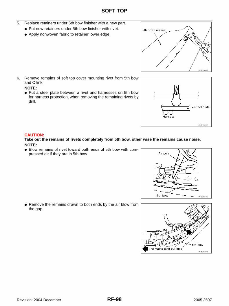
RF-98
SOFT TOP
Revision: 2004 December 2005 350Z
5. Replace retainers under 5th bow finisher with a new part.● Put new retainers under 5th bow finisher with rivet.● Apply nonwoven fabric to retainer lower edge.
6. Remove remains of soft top cover mounting rivet from 5th bowand C link.NOTE:● Put a steel plate between a rivet and harnesses on 5th bow
for harness protection, when removing the remaining rivets bydrill.
CAUTION:Take out the remains of rivets completely from 5th bow, other wise the remains cause noise.NOTE:● Blow remains of rivet toward both ends of 5th bow with com-
pressed air if they are in 5th bow.
● Remove the remains drawn to both ends by the air blow fromthe gap.
PIIB1308E
PIIB1597E
PIIB1014E
PIIB1015E

SOFT TOP
RF-99
C
D
E
F
G
H
J
K
L
M
A
B
RF
Revision: 2004 December 2005 350Z
7. Install 5th bow finisher to 5th bow.
8. Install 5th bow side finisher (RH/LH) to 5th bow.
9. Install new pads and fabric tapes.
10. Secure 5th bow finisher harness with new nonwoven fabric if necessary.
Installation1. Apply double faced adhesive tape for frame.
2. Put soft top cover on frame.
PIIB1309E
PIIB1412E
PIIB1599E
A: Upper side of 1st bow
B: Under side of 1st bow
C: Outer side of A link (between grommets)
D: Outer and under side of 1st bow edge
PIIB1322E
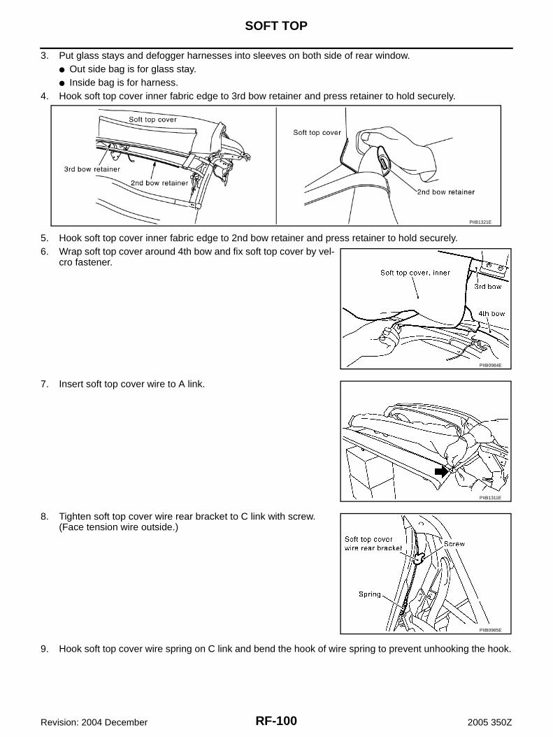
RF-100
SOFT TOP
Revision: 2004 December 2005 350Z
3. Put glass stays and defogger harnesses into sleeves on both side of rear window.● Out side bag is for glass stay.● Inside bag is for harness.
4. Hook soft top cover inner fabric edge to 3rd bow retainer and press retainer to hold securely.
5. Hook soft top cover inner fabric edge to 2nd bow retainer and press retainer to hold securely.6. Wrap soft top cover around 4th bow and fix soft top cover by vel-
cro fastener.
7. Insert soft top cover wire to A link.
8. Tighten soft top cover wire rear bracket to C link with screw.(Face tension wire outside.)
9. Hook soft top cover wire spring on C link and bend the hook of wire spring to prevent unhooking the hook.
PIIB1321E
PIIB0984E
PIIB1311E
PIIB0985E
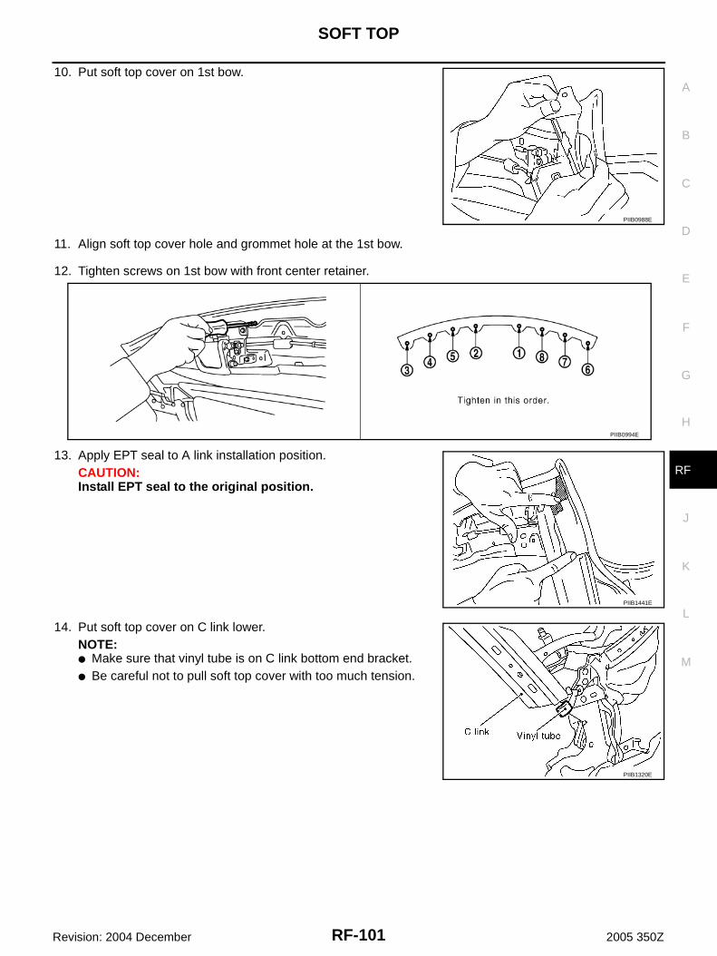
SOFT TOP
RF-101
C
D
E
F
G
H
J
K
L
M
A
B
RF
Revision: 2004 December 2005 350Z
10. Put soft top cover on 1st bow.
11. Align soft top cover hole and grommet hole at the 1st bow.
12. Tighten screws on 1st bow with front center retainer.
13. Apply EPT seal to A link installation position.CAUTION:Install EPT seal to the original position.
14. Put soft top cover on C link lower.NOTE:● Make sure that vinyl tube is on C link bottom end bracket.● Be careful not to pull soft top cover with too much tension.
PIIB0988E
PIIB0994E
PIIB1441E
PIIB1320E

RF-102
SOFT TOP
Revision: 2004 December 2005 350Z
15. Open 5th bow then secure soft top cover to 5th bow finisherupper surface with rivet.
16. Close 5th bow then wrap soft top cover around 5th bow.17. Secure soft top cover to 5th bow with rivet.
18. Secure soft top cover to C link with rivet.
19. Align screw hole on soft top cover and the bottom of C link, andthen tighten with screw.NOTE:● During tighten up the screw, insert a thin metal rod such as a
nail [diameter: 4mm (0.16in)] to a clip hole near the screw toalign holes of soft top cloth and its backing plastic plate, and Clink frame.
● Tighten screw while holding soft top at certain angle for easyscrew installation.
PIIB1313E
PIIB1003E
PIIB1315E
PIIB1299E
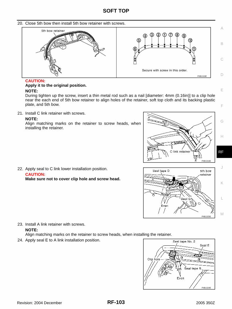
SOFT TOP
RF-103
C
D
E
F
G
H
J
K
L
M
A
B
RF
Revision: 2004 December 2005 350Z
20. Close 5th bow then install 5th bow retainer with screws.
CAUTION:Apply it to the original position.NOTE:During tighten up the screw, insert a thin metal rod such as a nail [diameter: 4mm (0.16in)] to a clip holenear the each end of 5th bow retainer to align holes of the retainer, soft top cloth and its backing plasticplate, and 5th bow.
21. Install C link retainer with screws.NOTE:Align matching marks on the retainer to screw heads, wheninstalling the retainer.
22. Apply seal to C link lower installation position.CAUTION:Make sure not to cover clip hole and screw head.
23. Install A link retainer with screws.NOTE:Align matching marks on the retainer to screw heads, when installing the retainer.
24. Apply seal E to A link installation position.
PIIB1319E
PIIB1316E
PIIB1325E
PIIB1324E
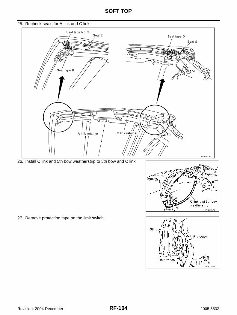
RF-104
SOFT TOP
Revision: 2004 December 2005 350Z
25. Recheck seals for A link and C link.
26. Install C link and 5th bow weatherstrip to 5th bow and C link.
27. Remove protection tape on the limit switch.
PIIB1323E
PIIB1317E
PIIB1286E

SOFT TOP
RF-105
C
D
E
F
G
H
J
K
L
M
A
B
RF
Revision: 2004 December 2005 350Z
28. Install A link weatherstrip.
29. Install front lock finisher and welt after closing soft top.30. Connect defogger harnesses at rear window.31. Install 5th bow operating strut rods (RH/LH).32. Install roof actuator (RH/LH). Refer to RF-107, "Removal and Installation of Roof Actuator" .33. Install soft top assembly to vehicle. Refer to RF-87, "Removal and Installation of Soft Top Assembly" .34. Check soft top open/close operation.35. Check door glass contact. Refer to GW-54, "FITTING INSPECTION" .36. Check for water leakage. Refer to RF-115, "Repairing Method for Water Leakage Around Doors" .NOTE:If there are wrinkles on the soft top cover, use a hair dryer to warm up the wrinkled area. Apply warm air fromthe hair dryer keeping the distance by 150 - 200 mm (5.9 - 7.8 in) and move the dryer to gently warm up softtop cover, for about 5 - 10 minutes until the wrinkle seems to be gone. Not to heat up soft top cover to much.
PIIB1318E
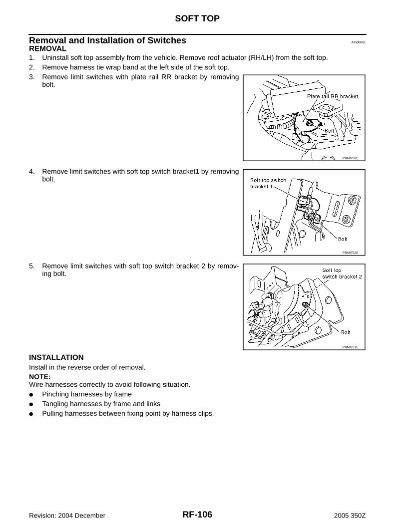
RF-106
SOFT TOP
Revision: 2004 December 2005 350Z
Removal and Installation of Switches AIS0060L
REMOVAL1. Uninstall soft top assembly from the vehicle. Remove roof actuator (RH/LH) from the soft top.2. Remove harness tie wrap band at the left side of the soft top.3. Remove limit switches with plate rail RR bracket by removing
bolt.
4. Remove limit switches with soft top switch bracket1 by removingbolt.
5. Remove limit switches with soft top switch bracket 2 by remov-ing bolt.
INSTALLATIONInstall in the reverse order of removal.NOTE:Wire harnesses correctly to avoid following situation.● Pinching harnesses by frame● Tangling harnesses by frame and links● Pulling harnesses between fixing point by harness clips.
PIIA9750E
PIIA9752E
PIIA9751E

SOFT TOP
RF-107
C
D
E
F
G
H
J
K
L
M
A
B
RF
Revision: 2004 December 2005 350Z
Removal and Installation of Roof Actuator AIS0060M
REMOVAL1. Remove soft top assembly. Refer to RF-87, "Removal and Installation of Soft Top Assembly" .2. Remove nuts and then remove roof actuator (RH/LH).
NOTE:If removal is difficult, rotate motor axis to remove them.
3. Disconnect soft top actuator harness connector.
INSTALLATIONInstall in the reverse order of removal.
Removal and Installation of 5th Bow Drive Unit AIS0060N
REMOVAL1. Uninstall soft top assembly from the vehicle. 2. Remove roof actuator (RH/LH) from the soft top.
NOTE:If removal is difficult, rotate motor axis to remove them.
3. Disconnect 5th bow operating rod (RH/LH) at the frame side bypulling out the holder.NOTE:This step will make the 5th bow up and down motion easier.
4. Make sure that the limit switch contact around the rotation axis of the 5th bow on the left side of soft top isprotected with tape.
5. Open the soft top manually, and put a stand under the 1st bow. Then fix the soft top not to move duringthis procedure.NOTE:Put a waste cloth between the front lock and the stand not to make any scratches to the soft top.
6. Remove the C link and 5th bow weatherstrip.
PIIB1167E
PIIB1167E
PIIA9755E
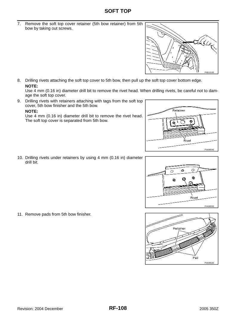
RF-108
SOFT TOP
Revision: 2004 December 2005 350Z
7. Remove the soft top cover retainer (5th bow retainer) from 5thbow by taking out screws.
8. Drilling rivets attaching the soft top cover to 5th bow, then pull up the soft top cover bottom edge.NOTE:Use 4 mm (0.16 in) diameter drill bit to remove the rivet head. When drilling rivets, be careful not to dam-age the soft top cover.
9. Drilling rivets with retainers attaching with tags from the soft topcover, 5th bow finisher and the 5th bow.NOTE:Use 4 mm (0.16 in) diameter drill bit to remove the rivet head.The soft top cover is separated from 5th bow.
10. Drilling rivets under retainers by using 4 mm (0.16 in) diameterdrill bit.
11. Remove pads from 5th bow finisher.
PIIB1010E
PIIA9854E
PIIA9855E
PIIA9853E

SOFT TOP
RF-109
C
D
E
F
G
H
J
K
L
M
A
B
RF
Revision: 2004 December 2005 350Z
12. Roll the soft top cover bottom edge up, and disconnect defoggerharness connector from the rear window glass.
13. Pull out glass stays from sleeves on each side of the rear win-dow glass.
14. Remove 5th bow side finisher (RH/LH) by removing screws.
15. Remove 5th bow finisher by pulling the finisher up.
16. Remove glass stays from 5th bow by removing screws from thebottom of the 5th bow.NOTE:● When removing glass stays, support 5th bow to avoid a bend
of glass stay. This bend may happen by the weight of the 5thbow and the tensile force of the tether from the soft top cover.
● Be careful not to damage the 5th bow nor to be hurt by thefalling 5th bow, because the 5th bow is heavy and movesfreely after removing glass stays.
17. Disconnect 5th bow drive unit harness connector.
PIIA9858E
PIIA9754E
PIIA9852E
PIIA9857E
PIIA9753E
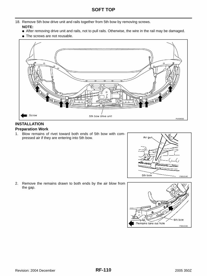
RF-110
SOFT TOP
Revision: 2004 December 2005 350Z
18. Remove 5th bow drive unit and rails together from 5th bow by removing screws.NOTE:● After removing drive unit and rails, not to pull rails. Otherwise, the wire in the rail may be damaged.● The screws are not reusable.
INSTALLATIONPreparation Work1. Blow remains of rivet toward both ends of 5th bow with com-
pressed air if they are entering into 5th bow.
2. Remove the remains drawn to both ends by the air blow fromthe gap.
PIIA9856E
PIIB1014E
PIIB1015E
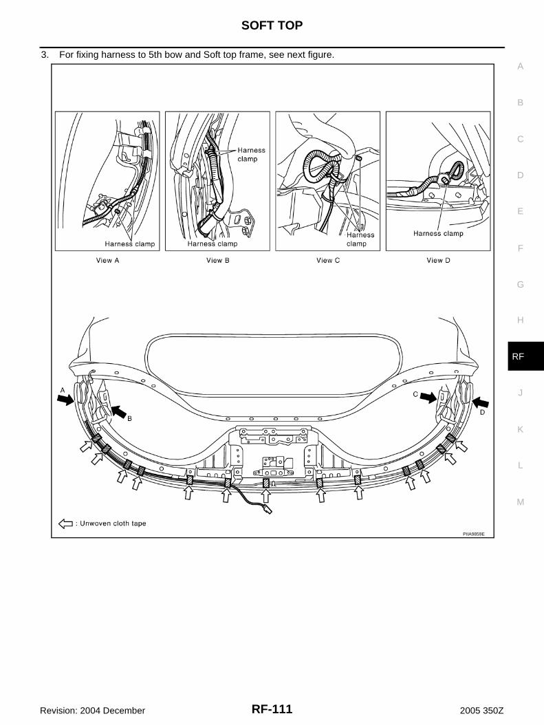
SOFT TOP
RF-111
C
D
E
F
G
H
J
K
L
M
A
B
RF
Revision: 2004 December 2005 350Z
3. For fixing harness to 5th bow and Soft top frame, see next figure.
PIIA9859E

RF-112
SOFT TOP
Revision: 2004 December 2005 350Z
PIIB0724E
PIIB0725E
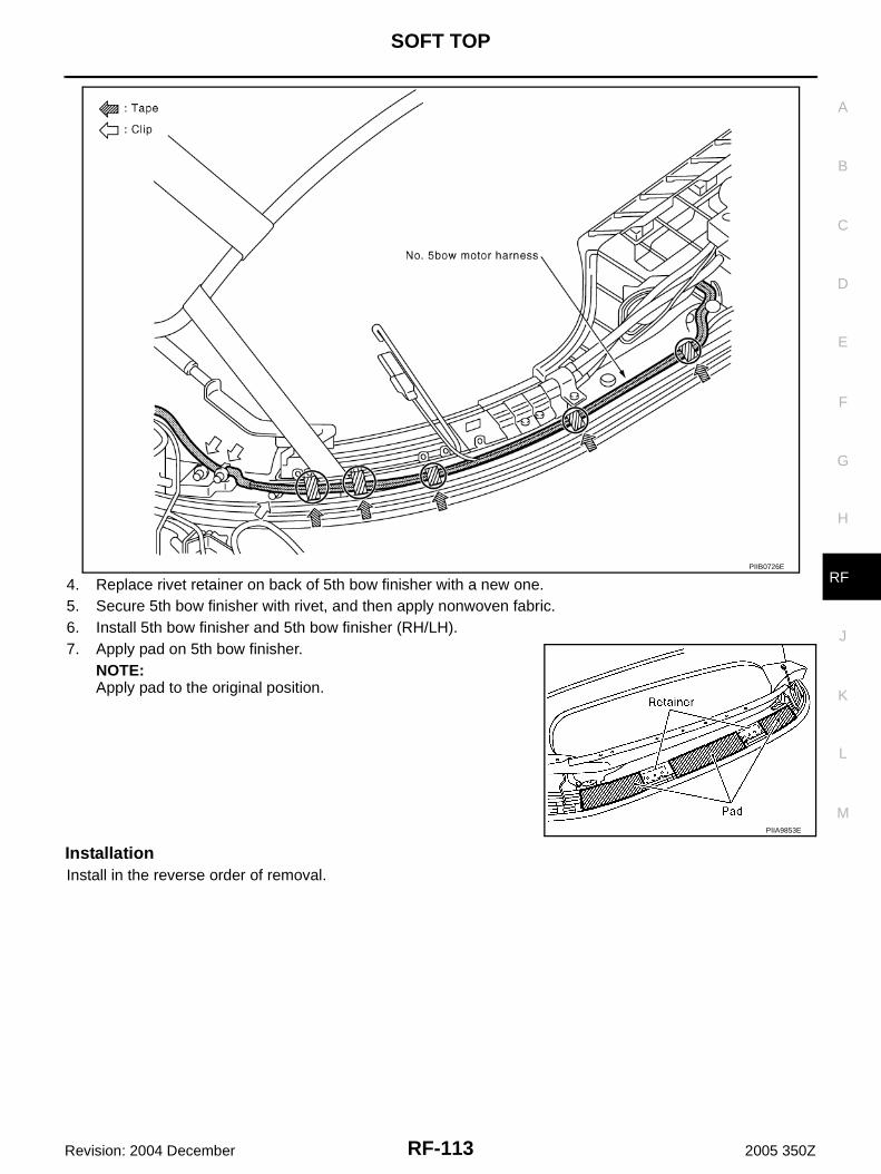
SOFT TOP
RF-113
C
D
E
F
G
H
J
K
L
M
A
B
RF
Revision: 2004 December 2005 350Z
4. Replace rivet retainer on back of 5th bow finisher with a new one.5. Secure 5th bow finisher with rivet, and then apply nonwoven fabric.6. Install 5th bow finisher and 5th bow finisher (RH/LH).7. Apply pad on 5th bow finisher.
NOTE:Apply pad to the original position.
InstallationInstall in the reverse order of removal.
PIIB0726E
PIIA9853E
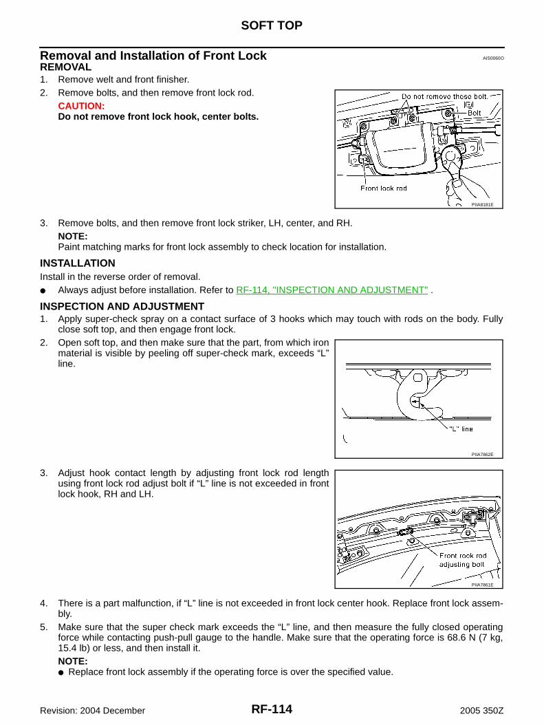
RF-114
SOFT TOP
Revision: 2004 December 2005 350Z
Removal and Installation of Front Lock AIS0060O
REMOVAL1. Remove welt and front finisher.2. Remove bolts, and then remove front lock rod.
CAUTION:Do not remove front lock hook, center bolts.
3. Remove bolts, and then remove front lock striker, LH, center, and RH.NOTE:Paint matching marks for front lock assembly to check location for installation.
INSTALLATIONInstall in the reverse order of removal.● Always adjust before installation. Refer to RF-114, "INSPECTION AND ADJUSTMENT" .
INSPECTION AND ADJUSTMENT1. Apply super-check spray on a contact surface of 3 hooks which may touch with rods on the body. Fully
close soft top, and then engage front lock.2. Open soft top, and then make sure that the part, from which iron
material is visible by peeling off super-check mark, exceeds “L”line.
3. Adjust hook contact length by adjusting front lock rod lengthusing front lock rod adjust bolt if “L” line is not exceeded in frontlock hook, RH and LH.
4. There is a part malfunction, if “L” line is not exceeded in front lock center hook. Replace front lock assem-bly.
5. Make sure that the super check mark exceeds the “L” line, and then measure the fully closed operatingforce while contacting push-pull gauge to the handle. Make sure that the operating force is 68.6 N (7 kg,15.4 lb) or less, and then install it. NOTE:● Replace front lock assembly if the operating force is over the specified value.
PIIA8181E
PIIA7862E
PIIA7861E

SOFT TOP
RF-115
C
D
E
F
G
H
J
K
L
M
A
B
RF
Revision: 2004 December 2005 350Z
● Make sure that operating force when replacing front weatherstrip, center weatherstrip, and rear weath-erstrip is 107.8 N (11 kg, 24.2 lb) or less.
Repairing Method for Water Leakage Around Doors AIS0060P
WATER LEAKAGE FROM AWater may be entering passenger room through back of front pillar.Cause: Butyl tape on back of glass run assembly may be separating from roof panel.
Repair Procedure 1Apply butyl tape on back of glass run assembly again, and correctinstalling position.
Water may be entering through connection between front pillar and front edge of soft top.Cause: There may be a gap between glass run assembly and weatherstrip of soft top.
1. Soft top assembly 2. Windshield glass 3. Door glass
4. Glass run assembly 5. A link weatherstrip 6. B link weatherstrip
7 C link and 5th bow weatherstrip
PIIA7647J
PIIB1168E

RF-116
SOFT TOP
Revision: 2004 December 2005 350Z
Repair Procedure 2Replace glass run assembly with a new one to eliminate the gapbetween glass run assembly and weatherstrip.
WATER LEAKAGE FROM BWater may be entering through door glass upper inside edge.Cause: There may be poor contact between A link weatherstrip of soft top and door glass.
Repair Procedure 3● Adjust door glass position frontward/backward or upward/down-
ward against soft top assembly.● Adjust door glass tilt contact by rotating adjusting bolt on regula-
tor lower edge.
CAUTION:Soft top assembly position may be incorrect when glass upperposition is low even if door glass adjustment is performed. Per-form soft top assembly adjustment, if necessary. Refer to GW-52, "FRONT DOOR GLASS AND REGULATOR" .
Adjust door glass tilt contact by rotating adjusting bolt on regulatorlower edge.
WATER LEAKAGE FROM CWater may be entering through a joint between soft top weatherstrips.Cause: There may be a step or a gap at the weatherstrips joint.
Repair Procedure 4● Replace weatherstrip with a new one.● If the step or the gap is not eliminated after replacing weather-
strip, then perform the following procedure.
PIIA7648E
PIIB1169E
PIIA7672E
PIIB1435E
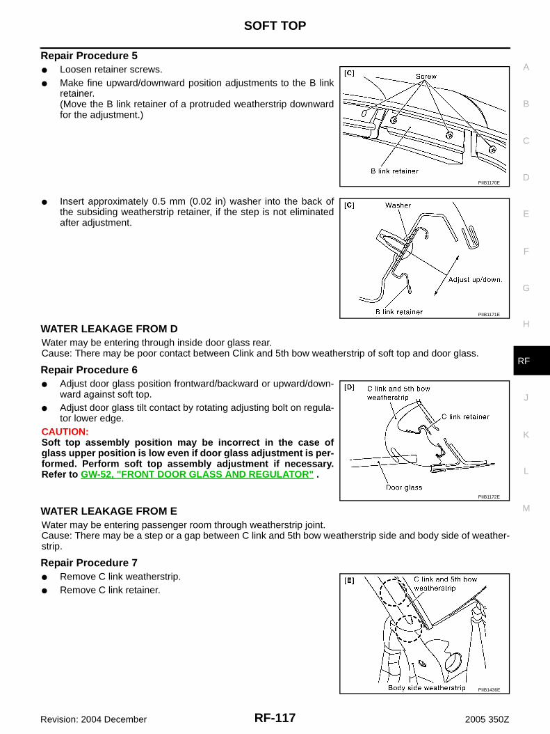
SOFT TOP
RF-117
C
D
E
F
G
H
J
K
L
M
A
B
RF
Revision: 2004 December 2005 350Z
Repair Procedure 5● Loosen retainer screws.● Make fine upward/downward position adjustments to the B link
retainer.(Move the B link retainer of a protruded weatherstrip downwardfor the adjustment.)
● Insert approximately 0.5 mm (0.02 in) washer into the back ofthe subsiding weatherstrip retainer, if the step is not eliminatedafter adjustment.
WATER LEAKAGE FROM DWater may be entering through inside door glass rear.Cause: There may be poor contact between Clink and 5th bow weatherstrip of soft top and door glass.
Repair Procedure 6● Adjust door glass position frontward/backward or upward/down-
ward against soft top.● Adjust door glass tilt contact by rotating adjusting bolt on regula-
tor lower edge.CAUTION:Soft top assembly position may be incorrect in the case ofglass upper position is low even if door glass adjustment is per-formed. Perform soft top assembly adjustment if necessary.Refer to GW-52, "FRONT DOOR GLASS AND REGULATOR" .
WATER LEAKAGE FROM EWater may be entering passenger room through weatherstrip joint.Cause: There may be a step or a gap between C link and 5th bow weatherstrip side and body side of weather-strip.
Repair Procedure 7● Remove C link weatherstrip.● Remove C link retainer.
PIIB1170E
PIIB1171E
PIIB1172E
PIIB1436E

RF-118
SOFT TOP
Revision: 2004 December 2005 350Z
● Apply approximately 5 mm (0.2 in) thick EPT seal to retainerback surface.
WATER LEAKAGE TESTVisually check for water leakage after repairing.1. 2 workers are required. One worker checks inside the vehicle, and the other one washes with water.2. Use 13 mm (0.51 in) diameter hose. Adjust water pressure by following method.
Hold the hose horizontally, and release water at 1000 mm(39.37 in) height from ground. Adjust the distance, between theground point just below the hose and the water dropping point,to reach 700 mm (27.56 in). (See the figure.)
3. Keeping the distance between the hose and the testing area by100 mm (3.94 in), apply water along the area 3 times. Duringapplying water, move the hose by 100 mm (3.94 in)/sec speed.
4. Visually check for water leakage.
PIIB1173E
PIIA8559E
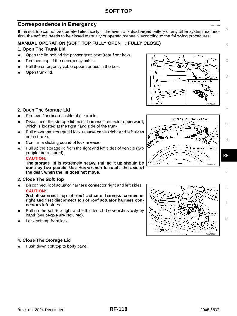
SOFT TOP
RF-119
C
D
E
F
G
H
J
K
L
M
A
B
RF
Revision: 2004 December 2005 350Z
Correspondence in Emergency AIS0060Q
If the soft top cannot be operated electrically in the event of a discharged battery or any other system malfunc-tion, the soft top needs to be closed manually or opened manually according to the following procedures.
MANUAL OPERATION (SOFT TOP FULLY OPEN � FULLY CLOSE)1. Open The Trunk Lid● Open the lid behind the passenger's seat (rear floor box).● Remove cap of the emergency cable.● Pull the emergency cable upper surface in the box.● Open trunk lid.
2. Open The Storage Lid● Remove floorboard inside of the trunk.● Disconnect the storage lid motor harness connector upperward,
which is located at the right hand side of the trunk.● Pull down the storage lid lock release cable (right and left sides
in the trunk).● Confirm a clicking sound of lock release.● Pull up the storage lid from the right and left sides of vehicle (two
people are required).CAUTION:The storage lid is extremely heavy. Pulling it up should bedone by two people. Use Hex-wrench to rotate the axis ofthe gear, when the lid does not move.
3. Close The Soft Top● Disconnect roof actuator harness connector right and left sides.
CAUTION:2nd disconnect top of roof actuator harness connectorright and first disconnect top of roof actuator harness con-nectors left sides.
● Pull up the soft top right and left sides of the vehicle slowly byhand (two people are required).
● Lock soft top front lock.
4. Close The Storage Lid● Push down soft top to body panel.
PIIA7591E
PIIB1437E
PIIA7593E

RF-120
SOFT TOP
Revision: 2004 December 2005 350Z
5. Lower The Soft Top 5th Bow● Remove both operating rod of soft top 5th bow.
CAUTION:Remove a holder of operating rod end.Simultaneously hold soft top 5th bow by hand when remov-ing the holder.
● Push in 5th bow to storage lid (do half lock).CAUTION:After closing the soft top manually according to the above pro-cedures, have the soft top operation system checked and/orrepaired by a NISSAN dealer as soon as possible.Avoid leaving the vehicle outside for long periods or driving athigh speed. As the rear of the soft top is not locked completely,this may allow wind and rain get into the vehicle.
MANUAL OPERATION (SOFT TOP FULLY CLOSE � FULLY OPEN)1. Remove The Luggage Floor Trim● Remove the rear floor box and luggage floor finisher upper. Refer to EI-41, "Removal and Installation (for
Roadster Models)" .
2. Cutting Storage Room Finisher● Cut storage room finisher from seat side.
3. Unlock The Storage Lid● Remove clip of inspection cover.
● Remove the storage lid inspection cover.● Pull the unlock wire then unlock the soft top 5th bow.
PIIA7594E
PIIA8845E
PIIA8844E
PIIB1438E
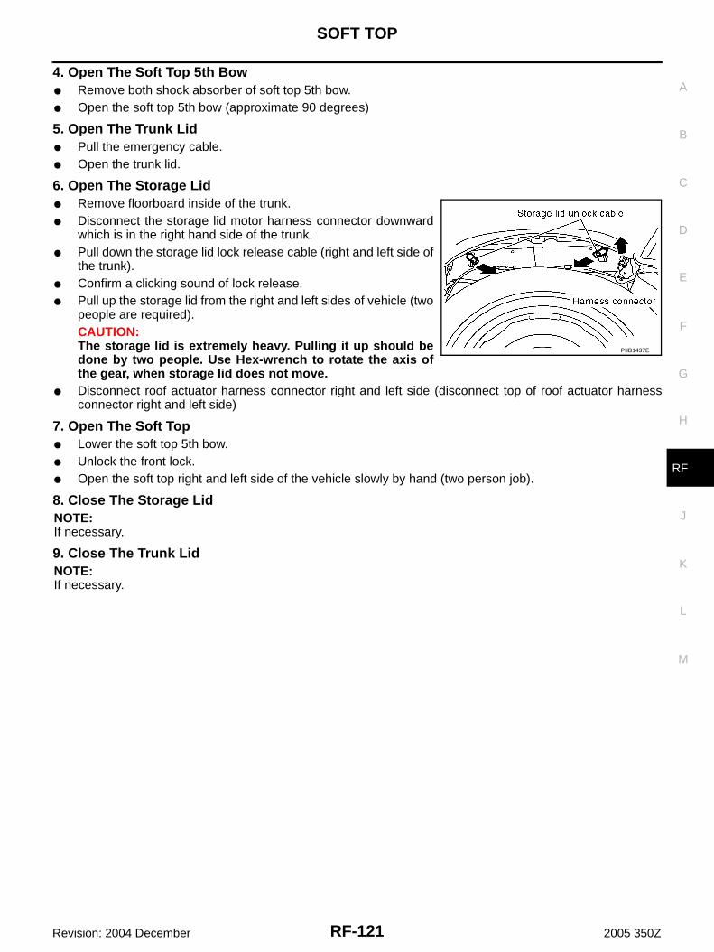
SOFT TOP
RF-121
C
D
E
F
G
H
J
K
L
M
A
B
RF
Revision: 2004 December 2005 350Z
4. Open The Soft Top 5th Bow● Remove both shock absorber of soft top 5th bow.● Open the soft top 5th bow (approximate 90 degrees)
5. Open The Trunk Lid● Pull the emergency cable.● Open the trunk lid.
6. Open The Storage Lid● Remove floorboard inside of the trunk.● Disconnect the storage lid motor harness connector downward
which is in the right hand side of the trunk.● Pull down the storage lid lock release cable (right and left side of
the trunk).● Confirm a clicking sound of lock release.● Pull up the storage lid from the right and left sides of vehicle (two
people are required).CAUTION:The storage lid is extremely heavy. Pulling it up should bedone by two people. Use Hex-wrench to rotate the axis ofthe gear, when storage lid does not move.
● Disconnect roof actuator harness connector right and left side (disconnect top of roof actuator harnessconnector right and left side)
7. Open The Soft Top● Lower the soft top 5th bow.● Unlock the front lock.● Open the soft top right and left side of the vehicle slowly by hand (two person job).
8. Close The Storage LidNOTE:If necessary.
9. Close The Trunk LidNOTE:If necessary.
PIIB1437E
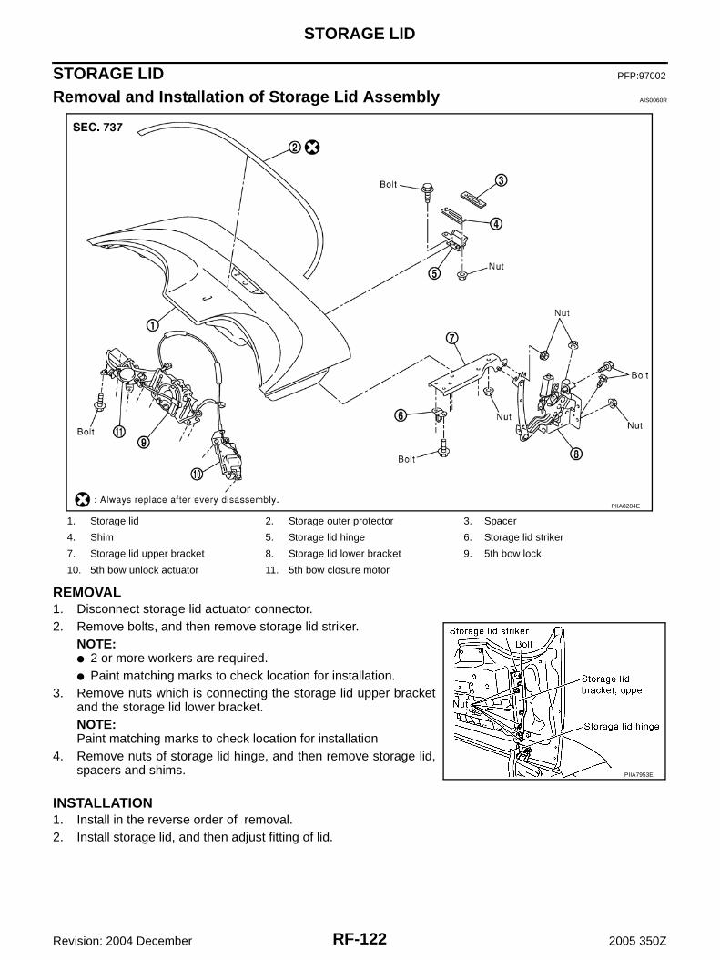
RF-122
STORAGE LID
Revision: 2004 December 2005 350Z
STORAGE LID PFP:97002
Removal and Installation of Storage Lid Assembly AIS0060R
REMOVAL1. Disconnect storage lid actuator connector.2. Remove bolts, and then remove storage lid striker.
NOTE:● 2 or more workers are required.● Paint matching marks to check location for installation.
3. Remove nuts which is connecting the storage lid upper bracketand the storage lid lower bracket.NOTE:Paint matching marks to check location for installation
4. Remove nuts of storage lid hinge, and then remove storage lid,spacers and shims.
INSTALLATION1. Install in the reverse order of removal.2. Install storage lid, and then adjust fitting of lid.
1. Storage lid 2. Storage outer protector 3. Spacer
4. Shim 5. Storage lid hinge 6. Storage lid striker
7. Storage lid upper bracket 8. Storage lid lower bracket 9. 5th bow lock
10. 5th bow unlock actuator 11. 5th bow closure motor
PIIA8284E
PIIA7953E
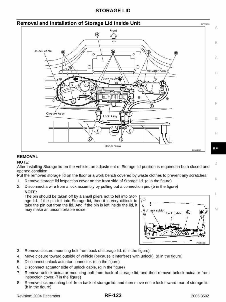
STORAGE LID
RF-123
C
D
E
F
G
H
J
K
L
M
A
B
RF
Revision: 2004 December 2005 350Z
Removal and Installation of Storage Lid Inside Unit AIS0060S
REMOVALNOTE:After installing Storage lid on the vehicle, an adjustment of Storage lid position is required in both closed andopened condition. Put the removed storage lid on the floor or a work bench covered by waste clothes to prevent any scratches.1. Remove storage lid inspection cover on the front side of Storage lid. (a in the figure)2. Disconnect a wire from a lock assembly by pulling out a connection pin. (b in the figure)
NOTE:The pin should be taken off by a small pliers not to fell into Stor-age lid. If the pin fell into Storage lid, then it is very difficult totake the pin out from the lid. And if the pin is left inside the lid, itmay make an uncomfortable noise.
3. Remove closure mounting bolt from back of storage lid. (c in the figure)4. Move closure toward outside of vehicle (because it interferes with unlock). (d in the figure)5. Disconnect unlock actuator connector. (e in the figure)6. Disconnect actuator side of unlock cable. (g in the figure)7. Remove unlock actuator mounting bolt from back of storage lid, and then remove unlock actuator from
inspection cover. (f in the figure)8. Remove lock mounting bolt from back of storage lid, and then move entire lock toward rear of storage lid.
(h in the figure)
PIIB1439E
PIIB1440E
RF-124
STORAGE LID
Revision: 2004 December 2005 350Z
9. Disconnect lock harness connector, and then remove lock from inspection cover. (j in the figure)NOTE:Turn lock catcher counterclockwise, and then face it to storage lid inspection hole side to remove becauseit interferes with storage lid when removing.
10. Disconnect closure harness connector, and then remove closure from inspection cover. (k in the figure)11. Disconnect unlock actuator, lock, and closure harness connectors from inspection cover.
(Push in harness connector clip tabs from back of storage lid using a screwdriver so as to remove.)
INSTALLATIONInstall in the reverse order of removal.
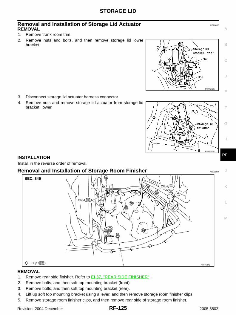
STORAGE LID
RF-125
C
D
E
F
G
H
J
K
L
M
A
B
RF
Revision: 2004 December 2005 350Z
Removal and Installation of Storage Lid Actuator AIS0060T
REMOVAL1. Remove trank room trim.2. Remove nuts and bolts, and then remove storage lid lower
bracket.
3. Disconnect storage lid actuator harness connector.4. Remove nuts and remove storage lid actuator from storage lid
bracket, lower.
INSTALLATIONInstall in the reverse order of removal.
Removal and Installation of Storage Room Finisher AIS0060U
REMOVAL1. Remove rear side finisher. Refer to EI-37, "REAR SIDE FINISHER" .2. Remove bolts, and then soft top mounting bracket (front).3. Remove bolts, and then soft top mounting bracket (rear).4. Lift up soft top mounting bracket using a lever, and then remove storage room finisher clips.5. Remove storage room finisher clips, and then remove rear side of storage room finisher.
PIIA7972E
PIIA8625E
PIIA7627E
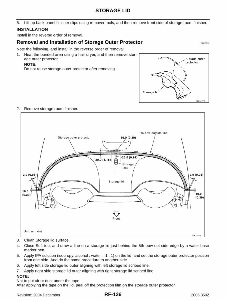
RF-126
STORAGE LID
Revision: 2004 December 2005 350Z
6. Lift up back panel finisher clips using remover tools, and then remove front side of storage room finisher.
INSTALLATIONInstall in the reverse order of removal.
Removal and Installation of Storage Outer Protector AIS0060V
Note the following, and install in the reverse order of removal.1. Heat the bonded area using a hair dryer, and then remove stor-
age outer protector.NOTE:Do not reuse storage outer protector after removing.
2. Remove storage room finisher.
3. Clean Storage lid surface.4. Close Soft top, and draw a line on a storage lid just behind the 5th bow out side edge by a water base
marker pen.5. Apply IPA solution (isopropyl alcohol : water = 1 : 1) on the lid, and set the storage outer protector position
from one side. And do the same procedure to another side.6. Apply left side storage lid outer aligning with left storage lid scribed line.7. Apply right side storage lid outer aligning with right storage lid scribed line.NOTE:Not to put air or dust under the tape.After applying the tape on the lid, peal off the protection film on the storage outer protector.
PIIB1177E
PIIB1443E

STORAGE LID
RF-127
C
D
E
F
G
H
J
K
L
M
A
B
RF
Revision: 2004 December 2005 350Z
● Secure left, right, and front end of storage room finisher with remaining part when removing using double-faced adhesive tape.
Adjustment of Storage Lid AIS0060W
ADJUSTMENT IN FULLY CLOSED POSITION
A-A Clearance AdjustmentLoosen nuts of storage lid hinge. Adjust storage lid until the clear-ance is within the specification.
B-B Clearance AdjustmentLoosen nut of storage lid striker lock, and adjust it until the clearance is within the specification.
C-C Clearance Adjustment, A-A Evenness AdjustmentLoosen nuts of storage lid hinge. Adjust storage lid height byexchanging or adding shim until the evenness is within the specifica-tion.
PIIA7884E
PIIA8857E
PIIA7954E
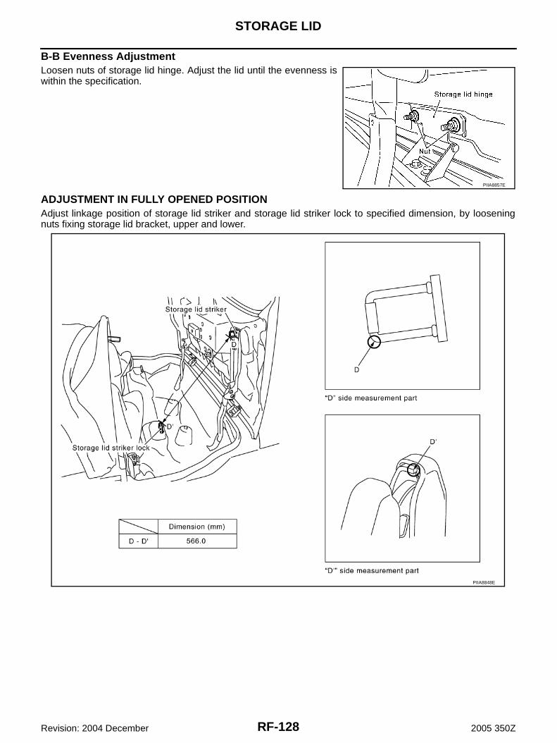
RF-128
STORAGE LID
Revision: 2004 December 2005 350Z
B-B Evenness AdjustmentLoosen nuts of storage lid hinge. Adjust the lid until the evenness iswithin the specification.
ADJUSTMENT IN FULLY OPENED POSITIONAdjust linkage position of storage lid striker and storage lid striker lock to specified dimension, by looseningnuts fixing storage lid bracket, upper and lower.
PIIA8857E
PIIA8848E
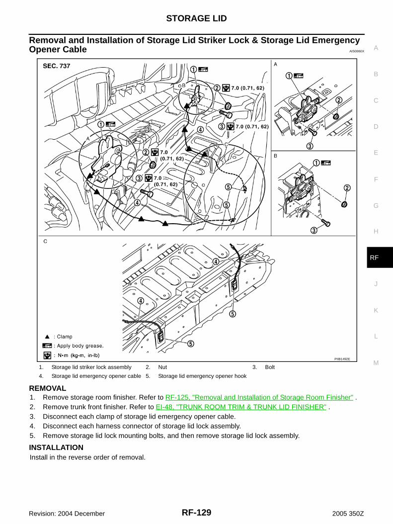
STORAGE LID
RF-129
C
D
E
F
G
H
J
K
L
M
A
B
RF
Revision: 2004 December 2005 350Z
Removal and Installation of Storage Lid Striker Lock & Storage Lid Emergency Opener Cable AIS0060X
REMOVAL1. Remove storage room finisher. Refer to RF-125, "Removal and Installation of Storage Room Finisher" .2. Remove trunk front finisher. Refer to EI-48, "TRUNK ROOM TRIM & TRUNK LID FINISHER" .3. Disconnect each clamp of storage lid emergency opener cable.4. Disconnect each harness connector of storage lid lock assembly.5. Remove storage lid lock mounting bolts, and then remove storage lid lock assembly.
INSTALLATIONInstall in the reverse order of removal.
1. Storage lid striker lock assembly 2. Nut 3. Bolt
4. Storage lid emergency opener cable 5. Storage lid emergency opener hook
PIIB1492E

RF-130
STORAGE LID
Revision: 2004 December 2005 350Z