rolls-royce silver cloud, ii, hi, and phantom v bentley s ... · pdf filerolls-royce silver...
TRANSCRIPT
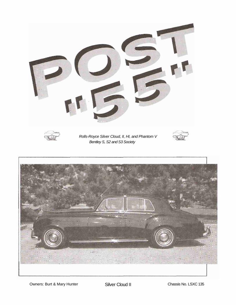
Rolls-Royce Silver Cloud, II, HI, and Phantom V Bentley S, S2 and S3 Society
Owners: Burt & Mary Hunter Silver Cloud II Chassis No. LSXC 135

Rolls-Royce Silver Cloud, II, III, and Phantom V Bentley S, S2 and S3
The Silver Cloud and Bentley 'S' Society
A great deal has happened since the last issue of Post "55". The time has literally flown by. The Society has held two Technical Seminars at Headquarters. The first seminar, held in March, covered the removal of the rear springs, and the replacement with a set of re-arched springs. We also re-shimmed the front springs to correct the standing height. The second seminar, held in November, covered the overhaul of shock absorbers. At this seminar we invited the participants to bring along their own shocks and overhauled these units. We also covered the removal and overhaul of a pair of SI front shocks and refit them to the car. In March next year it is our intention to hold a seminar on differential overhaul in Mechanicsburg. I look forward to meeting you at a seminar.
The Foundation of the RROC held an Engine Rebuilding Seminar at Sports Classics in MA in April this year. This seminar covered the rebuilding of a six cylinder engine from a MK VI. This engine is the forerunner of the Silver Cloud and Bentley "S" Type and any member with one of these cars would have benefited from knowledge gained at this seminar. In the future we will hold another seminar which will cover the fitting of that engine to the car and hopefully having the engine running by the end of that seminar. The session will be held at Headquarters. By attending this session you will help the Foundation with one of its goals - to put this donated Radford MK VI back on the road.
When you joined the Society, the form included a box for an e-mail address and if you provided us with this information, you should have received a "broadcast mailing" providing you with information about up-coming tech sessions and a monthly "Tech Tip". If you have an e-mail address and did not receive this broadcast mailing and would like to receive it, please send Larry Durocher an e-mail at: [email protected]
The Society Badges are now finished. Jim Sprague designed, produced and mailed the badges for the Society. This of course was no small task and we owe him a huge debt of gratitude. If you have not ordered a badge, then this may be a good time to do so. There are details in this magazine.
The last time I wrote to you I asked about help in organizing a "Cross Continent" trip to tie in with the 2004 celebrations. To date I have received an offer for the people on the trip to visit a very large and beautiful collection of post 55 cars in the St Louis area. John Dreyer a member from Toronto has offered to put some tentative routes together to start the ball rolling. We are going to need a great deal of all kinds of help to achieve this goal.
At the Business Meeting which was held at the Annual Meet in Lexington in August, I expressed my concern of how I am unable to give the Society the time needed to edit the Post "55". I therefore asked for volunteers to replace me as Editor of the Society magazine. I am happy to report that Debbie Habaker from Dallas, Texas has accepted the position. It is very important not to lull into the belief it is a one person job. All of the Society members should send in something to print. I will continue to supply the Tech Tips articles for the magazine. If we are going to have a newsletter worth reading, you the membership must take up the challenge and send in articles, tidbits, photos and thoughts.
My thanks to all who have supplied me with pictures, stories, articles on your cars. It was most enjoyable being the messenger. I hope there are as many or more willing people prepared to take the time to supply the material for future magazines.
S o c i e t y
Dear Society Member,
Contact: Ralph Curzon130 May field Drive Oakville, Ontario
L6H 1K7 Tel: (905) 844-2785
Edited by: RalphCurzon Nelia DoCouto

Rolls-Royce Silver Cloud, II, III, and Phantom VBentley S, S2 and S3
COVER STORY"My wife and I became seriously interested in Rolls-Royces after purchasing a Morgan and joining three of the northeastern Morgan clubs. We were struck by the fact that many Morgan owners also own a Rolls-Royce, a Bentley, or both. We quickly decided that a Rolls would be much more satisfactory touring car than a Morgan, whose boot consists of a luggage rack and a space behind the seat barely large enough for selected road kill. I, the impetuous member of our marital team, was gently dissuaded by my prudent wife from buying a number of disasters and near-disasters that were presented to us, including the popular GM-conversion Bentley, com-plete with everything except a flame job! Mary was aided in this by the wise advice of our good friend Tony Newton, who urged us to decide exactly which Rolls we liked rather than buying just any Rolls, and to then to examine several cars very thoroughly before making our purchase.
After several lessons from Tony, including a couple of hands-on inspections of actual cars, Mary and I felt brave enough to venture forth on our own to visit LSXC135, which then resided in St. Catherine's, Ontario. LSXC135 is a 1961 Rolls-Royce Silver Cloud II built sometime between November, 1960 and February, 1961.
After receiving what we assumed was the normal "sellers hype" on the car, we flew to St. Catherine's to see it. I was astounded to find that the car was at least three times better than described (and Mary said it was 300 times better than she had expected). Following Tony Newton's advice, we had commissioned a thorough mechanical review of the car.
I studied the log book and found that its owner had driven the car approximately 85 miles per year over the last 10 years. This "over-pampering" actually meant that some of the seals had dried out and the tires, which had less than 1,000 miles on them, really were not safe to use. Based on mechanical advice from Ralph Curzon of Hyphen Repairs in Toronto, we decided to make the purchase and have Ralph make the necessary repairs.
We originally attempted to make the official customs entry of the car at U.S. Customs near St. Catherines, so that we could then obtain our New Jersey plates and drive the car back once the repairs were finished.
Unfortunately, the customs officials, perhaps after noticing several entries in my passport for business trips I have taken to Colombia, apparently came to the conclusion that we must be smuggling something into the country. We endured a search of our brief cases, purses, etc. which took over an hour. Subsequently, the car was searched by an armed customs agent while an additional armed agent stood, hand on pistol, at the back of the car and I shivered at the front of the car (it was February at this post on the Canadian border}. We were then told that, even though the build sheet showed the car was originally built for the U.S., we could not prove it had actually been importedinto the U.S.,
so we would have to pay duty on the car. Rather than have this insult added to the time injury, we re-entered Canada with the car. Subsequently, thanks to the kindness of Tim Younes of the Rolls-Royce Owners Club, we were able to obtain certification that the original owner of the car was located in Pennsylvania.
LSXC135 was repainted approximately 15 years ago in the colors indicated on the original Rolls-Royce build sheet which was supplied to us courtesy of the Rolls-Royce Owners Club (Mason's black with a gold accent). The paint was nearly perfect but did require touch-up in a few areas. The car was first sent to the painter who had done the original work to have a few areas
with stone chips etc. repaired. Mechanically, the car, which has gone about 68,000 miles since new, was in excellent condition and required little more than some new seals, a thorough brake job and a rebuilt water pump.
The build sheet for LSXC135 stated that it had originally been fitted with Dunlop Buffalo white sidewall tires. I called the ^̂ ̂ archivist at the Dunlop Tyre Company in England, who checked the original mold draw-
ings and informed me that Dunlop Buffalos had a white sidewall approximately .4 inch wide, rather than the "gangster whites" Silver Clouds are often fitted with today. Ralph Curzon was able to obtain Pirelli radial tires with a white sidewall not much wider than the original Dunlop Buffalos.
Although the Dunlop Buffalos are standard bias tires, I am told by anyone that has ever switched that Clouds drive much better with radial tires.
LSXC135 has the original tan leather upholstery with which it was fitted at the factory. Over the years, the normal number of cracks in the dye itself had developed (the hides in this era were dyed with a surface dye).
S o c i e t y
Mary & Burt Hunter with LSXC 135

Rolls-Royce Silver Cloud, II, III, and Phantom V Bentley S, S2 and S3
- continued from page 3
Surprisingly, none of these cracks pene-trated through the leather itself. Ralph replaced the foam in the front seat and removed/restored the dye so that the interior still has the patina of age, but looks nearly new. I strongly recommend that Ralph comment on this process in a future article in this magazine, since the work came out so well.
The car as originally built did not have air conditioning. Ralph was able to secure the appropriate parts and construct an original design "under the fender" air conditioning system for us, utilizing existing vents and controls. The compressor, per Tony Newton, is even better than the one originally fitted. The only complaint
we have is that sometimes the air gets so cold we have to open a window to obtain balance.The car was also fitted with its original half-vacuum tube, half-transistor radio which, when it finally warms up and begins operating, makes you wonder if it is time for "War of the Worlds" to have its first anniversary rebroadcast. Ralph found a stereo expert just outside of Toronto who also owns two Rolls-Royces. This man fitted a tiny but powerful Pioneer AM/FM/Cassette/CD unit in the existing glove box without modification. It can be operated either manually or with a remote control (which is smaller than a credit card).
We drove the car home from Ralph's shop in Toronto on Labor Day, 1999. It currently occupies pride of place in a rented garage, but will soon be the star performer in a new carriage house which we are constructing to house the Cloud, an original 1966 Morgan Plus 4 Super Sport, and other players to be named (subject of course to the advice and consent of the chairman of the finance subcommittee of the acquisition committee, who has an obsolete veto, but would never exercise it against her loving husband).11
by Burt Hunter
Drop Window Motor/Mechanism Inspection/RebuildBy Lam/ Durocher (LSCX671)
A problem recently developed with the electric drop window unit on the rear passenger door of my Silver Cloud III. The window would lower properly. However, when I would attempt to raise the window, the unit emitted a loud grinding noise and could only be raised by pulling the window up simultaneously with my hands. Clearly, the door needed to be disassembled to determine the cause. Typical culprits are problems with the chain, poor grounds, etc.
Although the removal of the electric unit is well documented in the Workshop Manual, the inspection and rebuild is less clear. I decided to document my suggestions on this project. Please keep in mind that I am far from being an expert on this subject.
After you have removed the door handle and door panel, test the function of the window mechanism before proceeding further. Two of the simpler causes of
electric window problems are poor connections at the door panel toggle switch or a bad toggle switch. Before disconnecting any of the wires from the Lucar connectors, take a picture of the connections or, at least, record the connections. For reference purposes, the orange and red wires from the brake solenoid and motor go to one double sleeve, the green wires from the solenoid and motor go to the other double sleeve and the motor's black wire goes to the single sleeve.
If you are performing the test with an external power supply, such as a battery charger, set the current to 2 amps; the maximum current drawn by the motor is 3 amps. Connect the black motor wire and the green brake solenoid wire to the negative (usually black) side of the charger. Connect the orange wire from the brake solenoid to the positive side of the supply; you should hear a distinct click indicating that the brake solenoid has
been energized and lifted the brake plunger away from the brake drum. When you touch the green motor wire to the positive lead, the motor mechanism should move in the direction to lift the window. When you touch the red motor wire to the positive lead, the mechanism should move in the direction to lower the window. This test lets us bypass problems caused by problems at the toggle switch and problems at the Lucar connectors. Obviously, if the problem doesn't appear in this test, the problem may be the toggle switch, the sleeve connectors, or the wires from the switch to the Lucar connectors.
Chapter S, section S4, of the Silver Cloud workshop manual describes the steps required to remove the assembly from the door. Based on my limited experience of removing and inspecting two such assemblies, I would like to supplement the manual's instructions with the following recommendations:
The door assistor must be removed- continued on page 5
S o c i e t y

Roils-Payee Silver Cloud, II, III, and Phantom VBentley S, S2 and S3
-continued from page 4
to extract the window mechanism on rear doors. After you remove the cotter pin and check strap pin, make sure the rear door will not rotate so far that the rear door can be creased by the adjacent front body panel. With the check strap removed, only the bottom rubber insert keeps the door from pivoting too far.
Remove the required buffer stop, in my case the rear stop, and lower the window to the lowest position, before trying to remove the two 3/16 Alien screws which secure the pick-
up link to the support channel.
With the assembly removed from the car, it is worthwhile to redo the mecha-nism test. Be careful, don't move the chain so far that the pick-up link gets close to either sprocket. If the problem does not appear in this test, the window glass may be binding in the window channel or the problem may only appear under a load, such as the window load. It might be worthwhile to use a piece of wire to hang a weight (approximately 5 Ibs) from the pick-up link and redo the test under load. The window glass and metal frame weigh
approximately 3 Ibs; the drag from thewindow channel and other bits and pieces probably create an effective weight close to 5 Ibs.
At this point, the chain case can be re-moved from the motor casing by removing the four bolts/nuts shown in Figure 1. With the bolts removed, the case can be moved toward the motor sprocket and the chain case and chain can be removed as a unit.At this point, the chain and sprockets can be inspected for damage and wear.
if the chain needs to be replaced, one of the clips at the pick-up link must be removed. Figure 2 shows the details required for proper assembly. Note, the ends of the tensioning spring ride on the rollers. If you do remove the chain for cleaning and greasing, note the position of the pick-up link. When viewed from the inside of the car, the pick-up link is on the right strand of chain for right-hand doors and on the left strand for left-hand doors. Again, before proceeding with further disassembly, it might be worthwhile to redo the earlier tests with the chain case removed.
With the four chain case bolts removed, the four (three on earlier models) smaller bolts/nuts at the motor end are the only fasteners holding the two case halves together, see Figure 3. There are two additional nuts studs/nuts that protrude from the case. At this point, those nuts do not need to be removed, they bolt the brake solenoid assembly to the interior of the case.
Figure 3
The motor sprocket, see Figure 4, does not need to be removed to split the cases. However, it is easier to separate the two halves when the sprocket is removed and, ultimately, the sprocket needs to be removed to remove the internal nylon reduction gear for inspection. Use a punch to drive out the tapered pin.
Society
Figure 2Figure 1
-continued on page6
Rolls-Royce Silver Cloud, II, III, and Phantom V Bentley S, S2 and S3
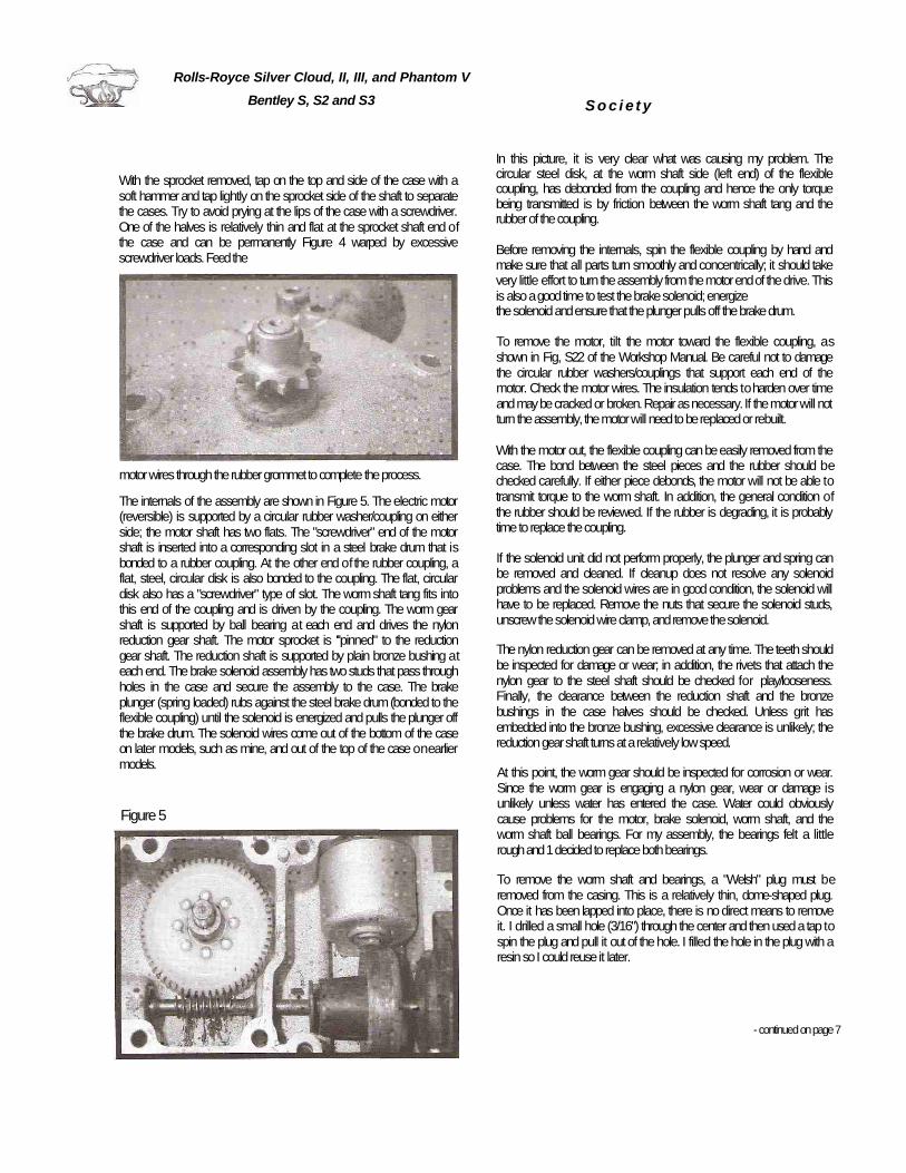
With the sprocket removed, tap on the top and side of the case with a soft hammer and tap lightly on the sprocket side of the shaft to separate the cases. Try to avoid prying at the lips of the case with a screwdriver. One of the halves is relatively thin and flat at the sprocket shaft end of the case and can be permanently Figure 4 warped by excessive screwdriver loads. Feed the
motor wires through the rubber grommet to complete the process.
The internals of the assembly are shown in Figure 5. The electric motor (reversible) is supported by a circular rubber washer/coupling on either side; the motor shaft has two flats. The "screwdriver" end of the motor shaft is inserted into a corresponding slot in a steel brake drum that is bonded to a rubber coupling. At the other end of the rubber coupling, a flat, steel, circular disk is also bonded to the coupling. The flat, circular disk also has a "screwdriver" type of slot. The worm shaft tang fits into this end of the coupling and is driven by the coupling. The worm gear shaft is supported by ball bearing at each end and drives the nylon reduction gear shaft. The motor sprocket is '''pinned" to the reduction gear shaft. The reduction shaft is supported by plain bronze bushing at each end. The brake solenoid assembly has two studs that pass through holes in the case and secure the assembly to the case. The brake plunger (spring loaded) rubs against the steel brake drum (bonded to the flexible coupling) until the solenoid is energized and pulls the plunger off the brake drum. The solenoid wires come out of the bottom of the case on later models, such as mine, and out of the top of the case on earlier models.
Figure 5
In this picture, it is very clear what was causing my problem. The circular steel disk, at the worm shaft side (left end) of the flexible coupling, has debonded from the coupling and hence the only torque being transmitted is by friction between the worm shaft tang and therubber of the coupling.
Before removing the internals, spin the flexible coupling by hand and make sure that all parts turn smoothly and concentrically; it should take very little effort to turn the assembly from the motor end of the drive. This is also agood time to test the brake solenoid; energizethe solenoid and ensure that the plunger pulls off the brake drum.
To remove the motor, tilt the motor toward the flexible coupling, as shown in Fig, S22 of the Workshop Manual. Be careful not to damage the circular rubber washers/couplings that support each end of the motor. Check the motor wires. The insulation tends to harden over time and may be cracked or broken. Repair as necessary. If the motor will not turn the assembly, the motor will need to be replaced or rebuilt.
With the motor out, the flexible coupling can be easily removed from the case. The bond between the steel pieces and the rubber should be checked carefully. If either piece debonds, the motor will not be able to transmit torque to the worm shaft. In addition, the general condition of the rubber should be reviewed. If the rubber is degrading, it is probably time to replace the coupling.
If the solenoid unit did not perform properly, the plunger and spring can be removed and cleaned. If cleanup does not resolve any solenoid problems and the solenoid wires are in good condition, the solenoid will have to be replaced. Remove the nuts that secure the solenoid studs, unscrew the solenoid wire clamp, and remove the solenoid.
The nylon reduction gear can be removed at any time. The teeth should be inspected for damage or wear; in addition, the rivets that attach the nylon gear to the steel shaft should be checked for play/looseness. Finally, the clearance between the reduction shaft and the bronze bushings in the case halves should be checked. Unless grit has embedded into the bronze bushing, excessive clearance is unlikely; the reduction gear shaft turns at a relatively low speed.
At this point, the worm gear should be inspected for corrosion or wear.Since the worm gear is engaging a nylon gear, wear or damage is unlikely unless water has entered the case. Water could obviously cause problems for the motor, brake solenoid, worm shaft, and the worm shaft ball bearings. For my assembly, the bearings felt a little rough and 1 decided to replace both bearings.
To remove the worm shaft and bearings, a "Welsh" plug must be removed from the casing. This is a relatively thin, dome-shaped plug. Once it has been lapped into place, there is no direct means to remove it. I drilled a small hole (3/16") through the center and then used a tap to spin the plug and pull it out of the hole. I filled the hole in the plug with a resin so I could reuse it later.
-continued on page 7
S o c i e t y

Rolls-Royce Silver Cloud, II, III, and Phantom VBentley S, 52 and S3
-continued from page 6
spacer at the clip end. Lightly tap the motor end of the worm shaft with a soft hammer to drive the shaft and the bearings from the case. The various pieces associated with the worm shaft are shown in Figure 6. The bearings are a light press fit on the shaft and can be easily removed.
Figure 6
At this point, all the parts should be degreased and both halves of the cases cleaned before starting reassembly, The new bearings should be well greased, pressed onto the worm shaft, and the entire assembly can be reinserted into the case. Use a center punch to lightly drive the worm shaft until the motor-end bearing seats against the case shoulder. Replace the spacer, insert the retaining clip, fill the plug cavity with grease, and then tap in the "Welsh" plug.
"Grease-Up" the worm shaft and nylon reduction gear and insert the reduction gear (sprocket end) into the case. Insert the flexible coupling into the "tang" of the worm shaft. Then insert the motor tang and tilt the motor into the case. I found the insertion could be done easier if I inserted the motor with only one circular washer (the worm gear side) in place and then tilted the motor slightly to insert the second rubber washer. With all the pieces back in one of the case halves, again test the solenoid and test the motor's ability to spin the gears in both directions.
Thread the motor wires through the rubber grommet in the other case halve, coat the mating faces of the face with a gasket sealer, and then push the two halves together. Use the four fasteners at the motor end to bolt the two halves together. Again, test the motors ability to spin the reduction gear shaft in both directions.
Start the tapered pin in one side of the motor sprocket. Make sure that the sprocket is placed with the shorter shoulder adjacent to the casing (see Figure 4). Support both ends of the sprocket shaft/case in a vise, align the holes in the sprocket and shaft using a tapered punch, and tap the tapered pin into the hole.
"Grease-Up" the chain, sprockets and the four rubber plugs in the chain case that serve as buffers between the chain and chain case in the direction transverse to the plane of the chain. Two of the plugs are shown in Figure 7. Earlier models of the chain case do not have the four rubber plugs/buttons. Slide the chain case over the motor sprocket and work the chain onto the motor sprocket. Make sure that the tension clip ends are riding on the rollersof the chain. Put the 4 chain case bolts/nuts though the motor casing and lightly tighten all four. Use a screwdriver between the motor sprocket and chain case to pretension the chain. Adjust the tension until, at midspan, each side of the chain can be moved V? in each direction.
Again, perform the solenoid test and test the motor's ability to drive the chain in each direction, If everything turns smoothly (not necessarily quietly), you are ready to put the unit back into the car,
DifferentialO VERHAUL
It has been at least thirty-five years since theSilver Cloud and Bentley "S" cars have beenproduced and in that time the rear axles in thesecars have been quietly going along with little or noattention. These cars were in every day use andthere was not a great deal of service required, ifthe oil level was maintained, and they went nicelyalong. However as these cars became collectorcars their usage became far less, and a phenom-ena appeared. Moisture in the rear axle sits on thebearings surfaces and this damages the surface.This causes a vibration to set up, which in turnloosens the bolts on the crown wheel. When thisoccurs the teeth on both the crown wheel andpinion break. To avoid this I would suggest, if thedifferential in your car has not been inspected inthe last ten or so years, you undertake the proce-dures of rebuilding the rear axle as shown in ourtechnical tips article. - continued on page 8
S o c i e t y
Figure 7
Rolls-Royce Silver Cloud, II, III, and Phantom V Bentley S, S2 and S3
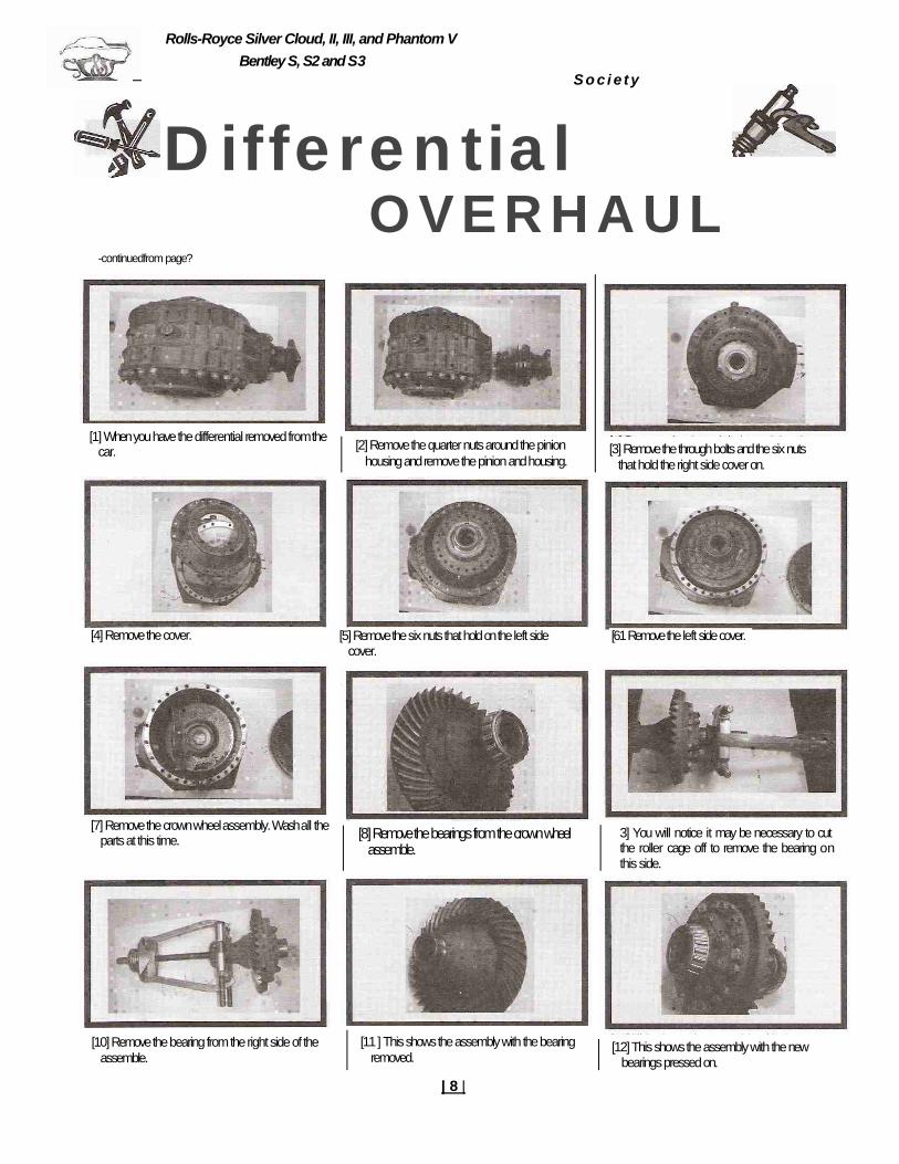
D iffe ren tia lO V E R H A U L
-continuedfrom page?
[1] When you have the differential removed from the car. [2] Remove the quarter nuts around the pinion
housing and remove the pinion and housing.[3] Remove the through bolts and the six nuts
that hold the right side cover on.
[7] Remove the crownwheel assembly. Wash all the parts at this time. [8] Remove the bearings from the crown wheel
assemble.3] You will notice it may be necessary to cut the roller cage off to remove the bearing on this side.
[10] Remove the bearing from the right side of the assemble.
[11 ] This shows the assembly with the bearing removed.
[12] This shows the assembly with the new bearings pressed on.
S o c i e t y
[4] Remove the cover. [5] Remove the six nuts that hold on the left side cover.
[61 Remove the left side cover.
| 8 |
Rolls-Royce Silver Cloud, II, III, and Phantom VBentley S, S2 and S3
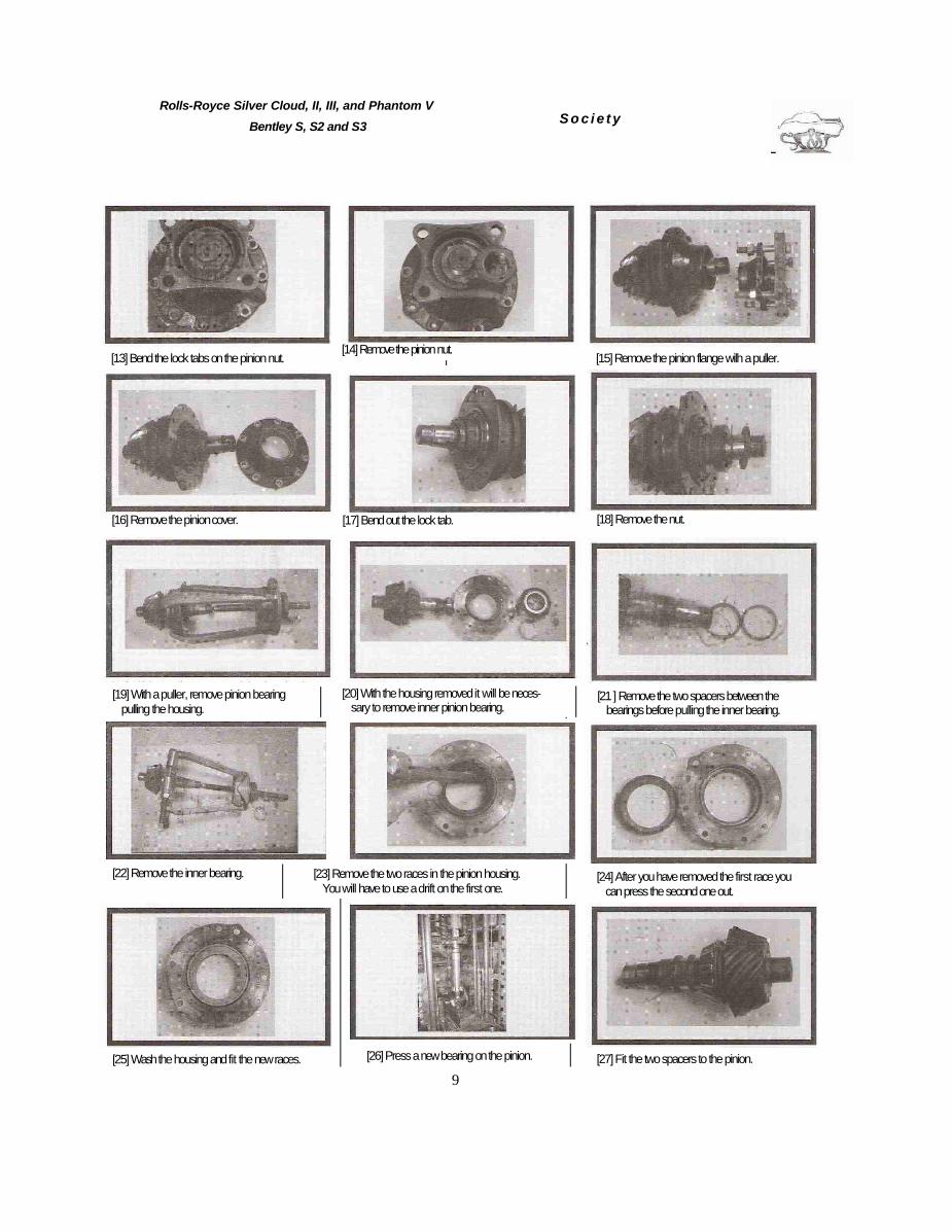
[13] Bend the lock tabs on the pinion nut. [15] Remove the pinion flange wilh a puller.
[19] With a puller, remove pinion bearing pulling the housing.
[20] With the housing removed it will be neces-sary to remove inner pinion bearing.
[21 ] Remove the two spacers between the bearings before pulling the inner bearing.
[22] Remove the inner bearing. [23] Remove the two races in the pinion housing. You will have to use a drift on the first one.
[24] After you have removed the first race you can press the second one out.
[25] Wash the housing and fit the new races. [26] Press a new bearing on the pinion. [27] Fit the two spacers to the pinion.
S o c i e t y
[14] Remove the pinion nut.
[18] Remove the nut.[16] Remove the pinion cover. [17] Bend out the lock tab.
9

Rolls-Royce Silver Cloud, II, III, and Phantom V
Bentley S, S2 and S3
[28] Fit the housing and press on the front pinion bearing. [29] Fit the thrower lock tab and nut. [30] Tighten the nut and bend in the lock tab.
[31] Fit a newfelt to the pinion cover. [32] Make sure you fit the felt well into the grove. [33] Fit the cover and the flange to the pinion.
[34] Fit the lock tab to the pinion. [35] Fit the nut, tighten the nut and bend the tabs on the lock nut.
[36] Remove the race, spacer and seal from the left side cover and clean off the surfaces.
[37] Fit a new seal and fit the spacer. [39] On the right side of the differential un-tab the nuts and remove them.
[40] Remove the seal holder and the Belville washers.
[41] Remove the spacer and push the race out (it probably has fallen through at this point).
[42] Remove the spacer from the seal holder.
S o c i e t y
[38] Fit a new race.
10
Rolls-Royce Silver Cloud, II, III, and Phantom VBentley S, 52 and S3
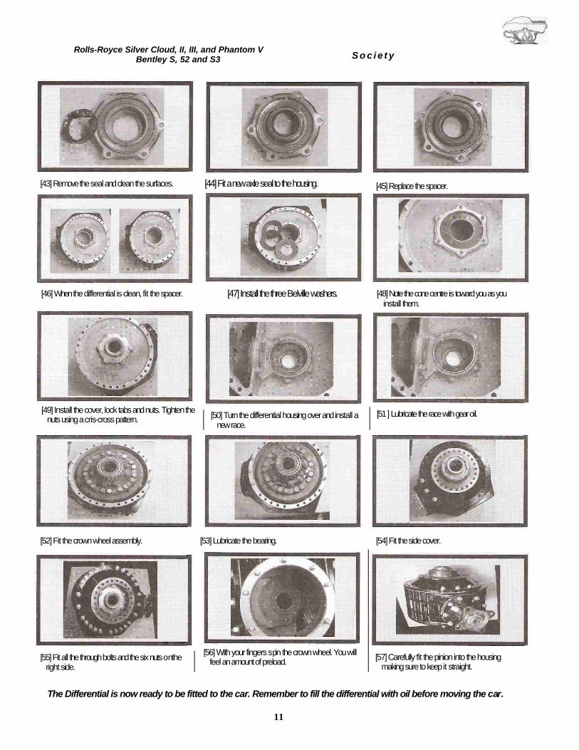
[43] Remove the seal and clean the surfaces. [44] Fit a new axle seal to the housing.
[46] When the differential is clean, fit the spacer. [47] Install the three Belville washers. [48] Note the cone centre is toward you as you install them.
[49] Install the cover, lock tabs and nuts. Tighten the nuts using a cris-cross pattern. [50] Turn the differential housing over and install a
new race.[51 ] Lubricate the race with gear oil.
[55] Fit all the through bolts and the six nuts on the right side.
[56] With your fingers spin the crown wheel. You will feel an amount of preload. [57] Carefully fit the pinion into the housing
making sure to keep it straight.
The Differential is now ready to be fitted to the car. Remember to fill the differential with oil before moving the car.
11
S o c i e t y
[45] Replace the spacer.
[52] Fit the crown wheel assembly. [53] Lubricate the bearing. [54] Fit the side cover.

Upcoming Technical Seminars
March 23 - 24, 2001
Differential OverhaulRROC Headquarters Mechanicsburg
Call 1-8OO- TRY RROC for details
Car Badges are still available;for orders in the U.S.A. contact Larry Durocher.
For Canadian orders contact Ralph Curzon.
III
I Ii
I I II II
!
I
J
I I
I
II!
L