rolling bearings in high-speed passenger traffic
TRANSCRIPT
IntroductionHow fast trains can travel has long been critical to railway
development.In 1830 the world speed record was 48 km/h (about 30
mph). Less than a century later (1903), in Berlin, a Siemens railcar exceeded 200 km/h (ca. 125 mph) (Ref. 1). And with streamlined steam locomotives, there were speed records set of more than 200 km/h prior to World War II.
These speed records were not achieved in regular service, however.
In fact, the first regular-service, high-speed train—the Shinkansen—debuted in Japan, 1964. Its maximum speed was 200 km/h (ca. 124 mph), which was boosted the following year to 210 km/h (ca. 130 mph); its average speed was about 163 km/h (ca. 100 mph). And because only narrow-gauge track of 1,067 mm-width was available in Japan prior to the Shinkansen era, this high-speed train rolled with a custom, made-to-fit track system devoid of any local or freight traffic.
The result: uninterrupted, high cruising speeds and short traveling times—right from the beginning (Ref. 2).
In Europe, one of the first regular-service lines operating at 200 km/h was the TEE—between Paris and Toulouse—with specially adapted SNCF locomotives (French National Railways). But the ultimate breakthrough in European high-speed rail history was the French TGV, in 1981, with a maxi-mum operating speed of 270 km/h (168 mph). Later versions reached maximum speeds of 300 km/h (186 mph) and 320 km/h (ca. 200 mph).
The German ICE was next. Still known in the early 1980s as the Inter City Experimental, the name was later changed to Inter City Express. The experimental-version ICE-V set a
(From Proceedings of the 2010 Joint Rail Conference—JRC2010—April 27-29, 2010. Reprinted with permission.)
Rolling Bearingsin High-Speed Passenger Traffic
Matthias R. Kilian
Management SummaryPassenger transport today moves significantly faster than ever before, often operating on separate tracks especially de-
signed for high-speed trains. Accordingly, high-speed rolling bearings are very important components in the bogies of trains today. Maximum train speeds currently reach 380 km/h (236 mph) in the latest high-speed applications—80% higher than in the earlier days of high-speed traffic. This paper presents two application examples of modern, high-speed traffic, together with some typical bearing arrangements and housings. It provides insight regarding measures taken in the bearing industry to meet the requirements of contemporary, high-speed traffic, and it cites important standards and regu-lations applicable for—but not restricted to—European applications. To be precise, the focus here is on journal bearings; information on traction motor bearings, transmission bearings and housings is included, but described in less detail.
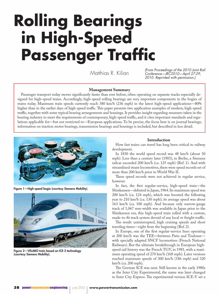
Figure 1—High-speed bogie (courtesy Siemens Mobility).
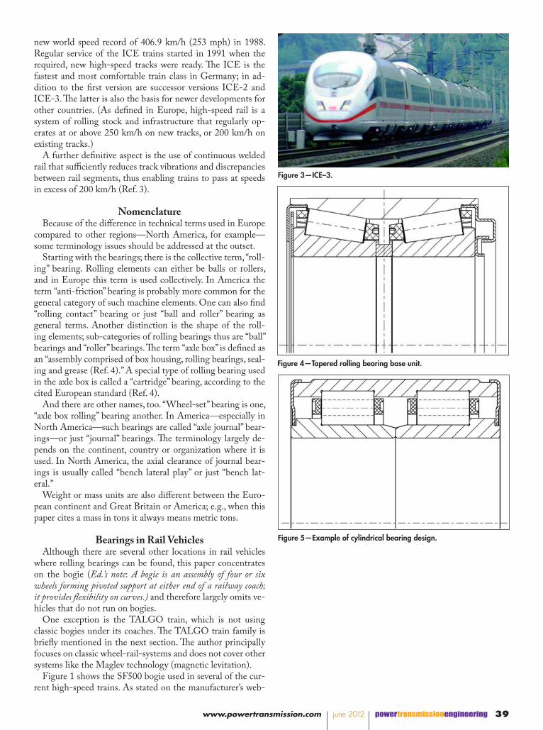
Figure 2—VELARO train based on ICE-3 technology (courtesy Siemens Mobility).
powertransmissionengineering june 2012 www.powertransmission.com38
new world speed record of 406.9 km/h (253 mph) in 1988. Regular service of the ICE trains started in 1991 when the required, new high-speed tracks were ready. The ICE is the fastest and most comfortable train class in Germany; in ad-dition to the first version are successor versions ICE-2 and ICE-3. The latter is also the basis for newer developments for other countries. (As defined in Europe, high-speed rail is a system of rolling stock and infrastructure that regularly op-erates at or above 250 km/h on new tracks, or 200 km/h on existing tracks.)
A further definitive aspect is the use of continuous welded rail that sufficiently reduces track vibrations and discrepancies between rail segments, thus enabling trains to pass at speeds in excess of 200 km/h (Ref. 3).
NomenclatureBecause of the difference in technical terms used in Europe
compared to other regions—North America, for example—some terminology issues should be addressed at the outset.
Starting with the bearings; there is the collective term, “roll-ing” bearing. Rolling elements can either be balls or rollers, and in Europe this term is used collectively. In America the term “anti-friction” bearing is probably more common for the general category of such machine elements. One can also find “rolling contact” bearing or just “ball and roller” bearing as general terms. Another distinction is the shape of the roll-ing elements; sub-categories of rolling bearings thus are “ball” bearings and “roller” bearings. The term “axle box” is defined as an “assembly comprised of box housing, rolling bearings, seal-ing and grease (Ref. 4).” A special type of rolling bearing used in the axle box is called a “cartridge” bearing, according to the cited European standard (Ref. 4).
And there are other names, too. “Wheel-set” bearing is one, “axle box rolling” bearing another. In America—especially in North America—such bearings are called “axle journal” bear-ings—or just “journal” bearings. The terminology largely de-pends on the continent, country or organization where it is used. In North America, the axial clearance of journal bear-ings is usually called “bench lateral play” or just “bench lat-eral.”
Weight or mass units are also different between the Euro-pean continent and Great Britain or America; e.g., when this paper cites a mass in tons it always means metric tons.
Bearings in Rail VehiclesAlthough there are several other locations in rail vehicles
where rolling bearings can be found, this paper concentrates on the bogie (Ed.’s note: A bogie is an assembly of four or six wheels forming pivoted support at either end of a railway coach; it provides flexibility on curves.) and therefore largely omits ve-hicles that do not run on bogies.
One exception is the TALGO train, which is not using classic bogies under its coaches. The TALGO train family is briefly mentioned in the next section. The author principally focuses on classic wheel-rail-systems and does not cover other systems like the Maglev technology (magnetic levitation).
Figure 1 shows the SF500 bogie used in several of the cur-rent high-speed trains. As stated on the manufacturer’s web-
Figure 3—ICE–3.
Figure 4—Tapered rolling bearing base unit.
Figure 5—Example of cylindrical bearing design.
39www.powertransmission.com june 2012 powertransmissionengineering

site (Ref. 5), this bogie is designed for ultimate riding comfort. Elaborate calculations on running-gear technology have led to a design distinguished by optimum properties of stability and comfort, as well as excellent track guiding behavior. The modular concept enables building the SF500 bogie as a driven bogie and also as a trailer bogie (Ref. 5).
In the bogie of a rail vehicle there are usually three major components of special interest for bearing suppliers.
With driven bogies these components are 1) the traction motor, 2) the transmission and, above all, 3) the axle box with the journal bearings (as they are called in North America).
For high-speed applications the axle box bearing system consists of a housing-and-bearing assembly.
The following will concentrate on the rolling bearings at the axle journal; housings, transmission bearings and traction mo-tor bearings are addressed at the conclusion.
Today’s High-Speed TrainsToday there are high-speed traffic systems on almost all
continents. Earlier generations of high-speed trains were mostly of the push-pull arrangement. In newer development of high-speed trains, however, the multiple-unit concept has established itself as the most common train configuration. The term multiple unit (MU) is used to describe a self-propelling train unit that is capable of coupling with other units of the
same or similar type while still being controlled from one cab (Ref. 6).
For high-speed applications the EMU (Electric Multiple Unit) is the dominating train type (Fig. 2). With combus-tion engine propulsion, such systems are called DMUs (Die-sel Multiple Units). The referenced German high-speed trains ICE-1 and ICE-2 are push-pull train configurations with electric-driven power heads at both ends. The ICE-1 had two power heads at the train ends and 12 passenger coaches in between. The main difference of the ICE-2 is that it employs the “half-train” concept. “Full” trains are configured with two push-pull trains linked together. A half-train can operate as an independent push-pull train unit; it has just one power head. On the other end there is a control car that is not driv-en, but is equipped with a driver’s cab; it takes on passengers just like the coaches. The engineer can shift from the power head to the control car and thus quickly change the driving direction. Six passenger coaches are fixed between the power head and the control car. For the main high-speed lines, two of these half-trains are usually coupled together, with the two control cars in the center. The passenger coaches of the ICE-1 and ICE-2 trains are non-driven in that there are only trailer bogies beneath them. The newer ICE–3 train (Fig. 3) and its relatives outside Germany are of the EMU design, with dis-tributed power; these trains no longer use power heads.
One of the most successful representatives of today’s high-speed traffic is the Siemens train family VELARO. The basics of this train are derived from the German ICE-3, but there are different versions of this train operating in different countries.
The train shown in Figure 2 for the Spanish state railway RENFE is called VELARO–E (E for España). The VELA-RO–RUS (Russia) is running on the 1,520 mm (59.8 in.) track gauge instead of the common 1,435 mm (56.5 in.). And there is the VELARO–CN (China) that is doing 350 km/h (ca. 220 mph) maximum service speed in the newest version.
The working name of the VELARO–CN project at Chi-nese Railways is CRH–3 (China Railway High-Speed). The number three reflects the ICE–3 origin of this train design. CRH–1 and CRH–2 were Bombardier and Kawasaki de-signs. Bombardier’s latest high-speed train is called ZEFIRO, along with other high-speed trains that are not as new but often have new versions. A selection of high-speed trains, to-
Table 1—Extract of applications and speedsTrain vmax. [km/h] vmax. [mph] Year
Shinkansen 200 124 1964210 313 1965300 186 1997
TGV 260 162 1981270 168 1983300 186 1989320 199 2001
ICE-3 300 186 2006320 199 2007
VERLARO– E 350 218 2007RUS 250 155 2009CN 350 218 2008
ZEFIRO 380* 236* *
*projectstatus
Figure 6—Journal details according to EN standards.
Figure 7—Detail A from Figure 6.
powertransmissionengineering june 2012 www.powertransmission.com40

gether with their maximum speeds and first year in operation, is listed in Table 1. But there are other high-speed trains not included in this listing; two of them should be mentioned—at least briefly.
Consider the AMTRAK train ACELA, running on the Northeast corridor in North America. The maximum speed of this train is not as high as with other applications, but it still operates under the definition of “high-speed” because it runs at more than 200 km/h on existing tracks, and in certain track sections reaches up to 240 km/h (ca. 150 mph).
The AGV train by ALSTOM is the successor of the TGV. It is already in service in Italy and might be selected for a Cal-ifornia high-speed rail project that is planned to connect Sac-ramento, San Diego, San Francisco and Los Angeles. Other high-speed rail applications in Europe are the Eurostar train and the Pendolino, by ALSTOM, the V250 train by Ansaldo-Breda, and the Thalys train.
The TALGO is different from other trains—predominantly with regard to its wheel suspension. The wheels of this articu-lated train are not joined by an axle and the coaches do not run on bogies. This suspension allows passive tilting of the train into curves, thus improving passenger comfort. The tilt-ing also allows the train to run faster on curves—especially on existing track. There are different generations of TALGO trains, including a couple of high-speed versions. TALGO is of Spanish origin but the trains run in several European coun-tries.
A significant difference in TALGO trains is that many of them are equipped with a variable gauge mechanism; i.e., with this device the train can cope with different track gauges by adjusting the wheels accordingly—to a closer or wider pitch. This allows throughput, for example, in cross-border traffic between countries with different track gauge, such as Spain and France. Indeed, much of the Iberian Peninsula’s gauge is different from the rest of Europe. For the TALGO 350, the top operational speed at Spanish state railways RENFE is 330 km/h (205 mph). The design top speed is 350 km/h (ca. 220 mph), but the speed is restricted to 330 km/h due to the pres-ent-gauged lines (Ref. 7).
Axle loads and bearing bore dimension. Compared to oth-er applications, axle loads for current high-speed vehicles are rather moderate. A reason for that is that with most high-speed applications, the traction force is distributed along the entire train instead of using push-pull technology as in the earlier days of high-speed traffic. The Siemens VELARO trains, for example, are of the EMU type (Electric Multiple Unit). With the VELARO–CN project, every second bogie of the train is driven, and the Russian-version VELARO–RUS has a similar concept. The axle loads of such applications are about 17–18 tons, depending on the train version. Based on axle load, the journal diameters are specified either as 130 mm (5.12 inch) or 150 mm (5.9 inch); these are also the bore diameters of the corresponding rolling bearings. With EMU concepts, the journal dimensions, and thus the bearing size, are kept identical for the entire train configuration. They can, however, vary between different versions within one train family. In push-pull applications like the German ICE–1 and ICE–2 trains, the axle loads are different for the power heads
and the coaches. For the ICE–1 and ICE–2, the power head axle load is 19.5 metric tons. The axle load of the passenger coaches in between these power heads is 16 metric tons. The newer-generation ICE–3, which is an EMU arrangement, has maximum axle loads of 16 metric tons throughout the entire train.
Rotational speeds. With wheel diameters of 830 mm (33 inch), a common diameter of the worn wheel and vehicle ve-locities of 350 or 380 km/h (218 or 236 mph), the rotational speed of the bearings of such high-speed applications results in 2,200 and up to more than 2,400 rpm. For a bearing the size of the described journal bearings, this is a rather high rotational speed and is not attainable using previous designs without modifications.
Figure 8—Bearing principle example of a high-speed train.
Figure 9—High-speed bearing with alternative sealing design.
41www.powertransmission.com june 2012 powertransmissionengineering
Bearing arrangements. From the axle box bearing viewpoint there are two main concepts used for high-speed applications: cylindrical roller bearings and tapered roller bearings.
Two-row tapered roller bearing units (Fig. 4) dominate the high-speed market at the moment. The bearings are usually designed as so-called “cartridge bearings.” Per definition (Ref. 4), these are rolling bearings with two or more rows of roll-ing elements within a single outer ring, greased and equipped with integral seals. Besides the bearings of the tapered de-sign there are also cylindrical roller bearings used in railway axle boxes (Fig. 5). These journal bearings are cartridge bear-ings with cylindrical rolling elements, usually arranged in two rows. They are supplied as greased-and-sealed units, as are tapered cartridge bearings. Such bearings are often used in European locomotives for push-pull trains with non-driven coaches. The cylindrical bearing unit design, for example, is also used for floating bearings on the middle axle in three-axle bogies of heavy locomotives.
European Standards and RegulationsThis part of the paper describes the most important stan-
dards that bearing manufacturers have to follow during the development, design, production and testing of railway roll-ing bearings. In addition to the standards directly referring to bearing issues, there are standards dealing with compo-nents around the axle box bearing, such as the axles them-selves. Details of these often are important for certain parts of the rolling bearing design as well. Besides some rather general
standards for rolling bearings, there are three railway-specific standards in Europe (European Norm):
The first one is probably also the most important: EN12080 (Ref. 4)/Railway Applications: Axle Boxes/Rolling Bearings. Some important information on this standard is given in the Quality Assurance section of this paper.
Next in the range of standards is EN12081 (Ref. 8) for lu-bricating greases. This standard covers items like consistency, traceability, packaging and, most of all—the approval process for greases.
The last is EN12082 (Ref. 9), which describes the perfor-mance testing of axle boxes. Since the testing defined here is much different from other testing methods (e.g., the AAR method), there is a short description of important characteris-tics under the topic Product Validation.
These mentioned standards all relate to the axle box bear-ings themselves. However, in the project work and design phase of an axle box arrangement, some other standards and regulations have to be taken into account.
There are also standards for the axles of railway vehicles:EN13103 Railway Applications: Wheels Sets and Bogies/
Non-Powered Axles/Design Method (Ref. 10).EN13104 Railway Applications: Wheel Sets and Bogies/
Powered Axles/Design Method (Ref. 11).In both standards the details shown in Figure 6 are used
to specify the axle design. An important standardized fact is that the edge on the axle journal (A, Fig. 6) has to meet the hardened and ground part of the bearing inner ring bore some distance away from the spot where the bearing bore runs over into the chamfer. This is shown in detail in Figure 7, where 1 points to the start of the bearing chamfer or to the end of the cylindrical bearing bore, and 2 marks the distance of this spot to the edge on the axle journal. The reason for this require-ment is to prevent axle fracture. When the inner ring’s transi-tion to the chamfer contacts the cylindrical part of the jour-nal outer diameter, there can be an indentation formed under the influence of high loads and bending under rotation. Com-pared to the hardened bearing inner ring, the axle journal ma-terial is much lower in hardness. Thus the indentation can lead to a serious problem as it can mark the start of a surface crack. The crack can then expand continuously from the influence of the bending under rotation and finally cause a fracture of the axle. With the specified arrangement (Fig. 7) the axle journal is prevented from damage by the bearing chamfer.
Enhanced Material PropertiesMaterial cleanliness has always been a key factor of any
bearing component involved in rolling contact. Non-metallic inclusions inside the material that are filtered out in the liquid phase of the steel-producing process have to be minimized and kept as tiny as possible. Such inclusions are mainly oxides and sulfides, and they undermine rolling bearing life by allowing the initiation of fatigue failures. Under the influence of high loads—which stresses the surface and subsurface of the race-ways—fatigue-based modifications of the material structure take place and lead to a reduction of bearing life. This failure mechanism is incorporated into the classic lifetime calcula-tion by a material factor. This material factor would be higher
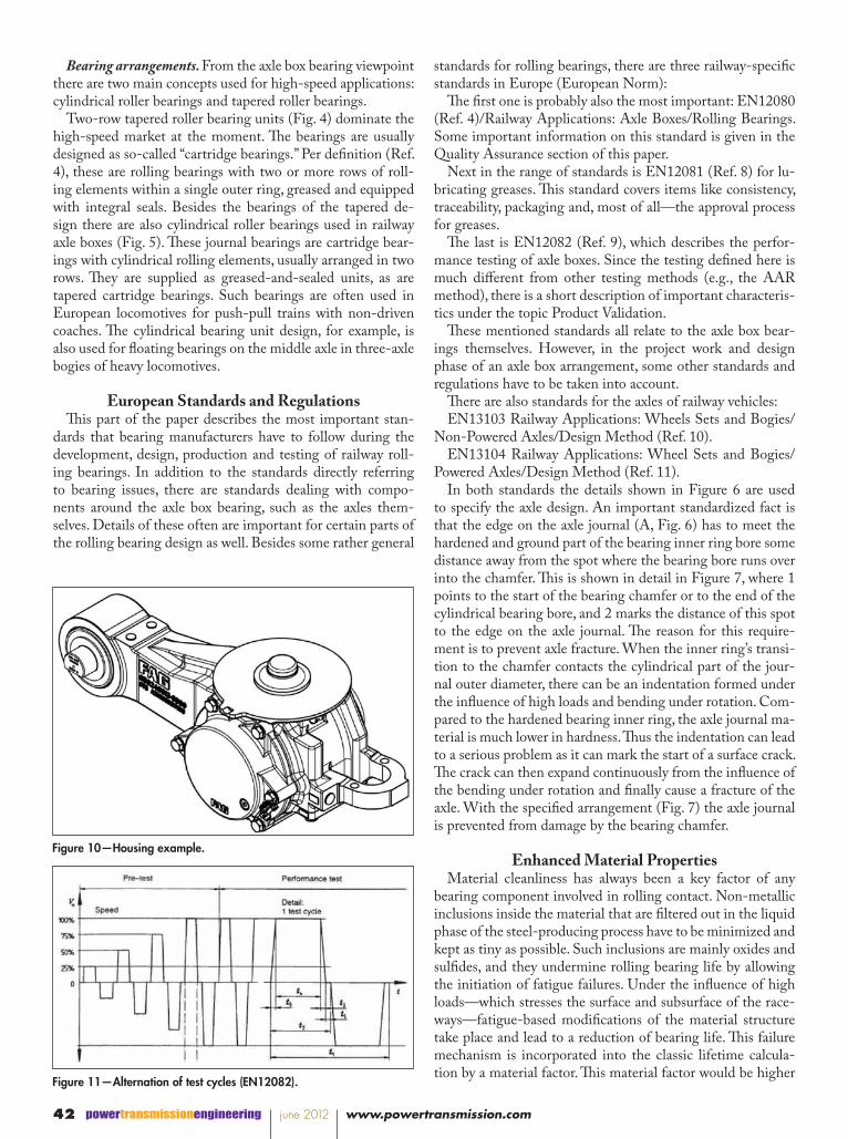
Figure 10—Housing example.
Figure 11—Alternation of test cycles (EN12082).
powertransmissionengineering june 2012 www.powertransmission.com42

when using special material qualities with further minimized inclusions. Steel that is perfect—completely free of any inclu-sions—does not exist, given the current state of technology. But for particularly demanding applications it is sometimes necessary to increase the fatigue lifetime of the bearings. This can be done by selecting bearing steel with advanced clean-liness requirements, meaning that the bearing manufacturer specifies an improved material compared to the standard axle box bearing quality. This is often done in combination with a more sophisticated heat treatment.
Material and/or surface and precision improvements are the most effective measures in creating higher-quality bearings for high-speed applications; special surface coatings are an-other option. A further improvement in material cleanliness exists in vacuum re-melted steel. However, energy consump-tion is much higher with several of its melting steps and there is a certain scrap content with any step. Furthermore, the low-er quantity in tons feasible for the re-melting processes makes it a very costly production. These factors all contribute to a considerably higher material cost for re-melted steel in com-parison to the current standard for axle box rolling bearings.
Figures 8 and 9 are examples of complete arrangements of journal bearings together with housings for high-speed trains.
Bearing LubricationThe grease quantity inside the bearing must be adapted to
the relatively high rotational speeds, and consistency needs to be suitable for high-speed traffic.
Also, environmental conditions in the area where the train is operating have to be taken into account when selecting a suitable grease type. Base oil type and thickener are only two aspects to be considered when forming a bearing lubricant. An adjusted selection of additives is important and requires a lot of experience. The determination of grease viscosity and grease amount is also largely influenced by the specific oper-ating conditions of the application. The grease viscosities for high-speed operation usually are somewhat lower than those of other applications. Grease suppliers and bearing manufac-turers typically share their knowledge for the development of greases with outstanding performance.
Most challenging in terms of lubrication is the definition of the appropriate grease quantity for a specific application. Although theoretically there is space enough to put some re-serves of grease into the bearing in order to reach long service intervals, high-speed bearings are extremely sensitive to over-greasing. Too much grease creates a temperature rise caused by the churning motion of the grease when it cannot escape from the raceway area to nonrotational sections of the bear-ing. This is a rather well-known finding. However, with higher speeds this aspect is even more critical. The performance test criteria described in this paper’s Quality Assurance section can only be fulfilled with an elaborate consideration of the grease amount and grease distribution inside the bearing. The currently valid edition of EN12080 requires that the grease distribution has to be agreed upon and documented between customer and contractor, in addition to the designation and quantity of the grease.
Quality ManagementThe Association of American Railroads (AAR) issues a sep-
arate manual—the M-1003—as part of their series of manu-als of Standards and Recommended Practices that deals ex-clusively with quality management issues.
The AAR rules and approvals are not only used in America but also in other parts of the world. However, these rules are mainly for freight applications and thus neither suitable nor sufficient for high-speed passenger traffic systems.
There are different international standards for quality man-agement systems, as most readers are well aware—ISO 9001, ISO9004 and TS16949, for example. And yet, none of these cover special railway topics. Thus within the last few years there was a new quality management standard developed es-pecially for railways: IRIS (Ref. 12). The International Rail-way Industry Standard has its roots in Europe but is appli-cable worldwide, as the name indicates. IRIS is issued by the Association of the European Rail Industry; it is a globally rec-ognized standard—unique to the railway sector—for evalua-tion of management systems. Its main objective is to improve the quality in the rail sector by reduction of efforts and costs (Ref. 13).
IRIS is based on the ISO 9001 structure and adds railway-specific requirements, especially on project management, de-sign, RAMS (reliability/availability/maintainability/safety) and LCC (life cycle costs). The standard contains both man-datory and optional requirements. The audit results are scored, thus it is more robust than a pass/fail system. One might rec-ognize some sort of analogy to ISO/TS16949, though IRIS exceeds the requirements in many ways. The second edition of the standard was issued in June 2009 and replaces the 2006 version. Many suppliers to the rail industry are certified ac-cording to IRIS. As of June 2009 there are 244 companies certified in 23 countries on five continents (Ref. 6).
Continual improvement is a basic tenet of IRIS that en-compasses the entire railway business sector.
Figure 12—Transmission example with hollow shaft.
43www.powertransmission.com june 2012 powertransmissionengineering

Quality AssuranceWhile this paper has dealt with quality management and
related systems, following is some information about actual quality assurance measures carried out on journal bearings. As already mentioned, EN12080 is the main normative instruc-tion for axle box bearings in Europe. Although this European standard affords much leeway to project-specific agreements between customer and supplier of railway axle box bearings, there is a variety of mandatory requirements when bearings are ordered and produced according to this standard.
Extensive, non-destructive testing is carried out on all jour-nal bearings per EN12080. This includes 100%-ultrasonic testing of the rings so that any subsurface defects in the mate-rial can be detected, and a crack inspection to detect surface fissures. Rollers are 100%-eddy-current-tested and there are hardness tests on rollers and rings for random samples. For all assembled bearings the axial clearance (bench lateral) is mea-sured and all inspection results are 100%-documented.
HousingsThe housing is an essential component of the axle box sys-
tem. Bearings in low-speed applications (especially freight cars) often run with housings connected to the bogie solely by open adapters, or the housings are of a rather simple de-sign that does not give full circumferential support. Full-bore housings (Fig. 10) allow the use of through-hardened bearing rings made of chromium steel—the most widely used material for rolling bearings in Europe.
Without the use of full-bore housings, the bearing outer rings are not equally supported on the entire circumference and the load distribution at the outer rings is less favorable. Bearing rings are then subject to distortion, and through-hardened rings can break under the influence of such de-formation. This is why high-speed applications are equipped with full-bore housings or with split housings that supply the same function as full-bore housings when the split parts are mounted together. Split housings enable the dismounting of the wheel set without removing the wheels from the axle.
Validation and Performance TestingThe European Standards series for axle boxes also covers
testing and validation. EN12082 standard (Ref. 9) deals with this topic and requires that any new axle box design under-go extensive performance testing with demanding test con-ditions. Unlike the durability testing according to AAR, the EN12082 rig performance test applies a relatively high lateral load (in axial direction) to the journal bearings. The standard uses the terms “axial force” and “radial force.” Bearings that undergo the AAR durability test are loaded only in the radial direction (vertically). Whereas the radial force is constant, the axial force applied during EN testing is alternating in two di-rections. The test cycles consist of acceleration from zero speed to test speed, running with test speed for some time and then decelerating to a stop; the next cycle then starts in the op-
posite direction (the sense of rotation is changed). Figure 11 illustrates the alternation of test cycles and shows how the speed is progressively increased during the pre-test phase.
There is a reference vertical load F0 calculated as:F0 = (1/j)•mmax•g
where:m is the vehicle mass and j is the number of wheel sets (axles)
Then the radial force is defined as:Fr =0.6•(F0 – m0•g)
and the axial force as:Fa=0.255•(104 + F0/3)
With a sample vehicle load of 64 tons (common for high-speed passenger coaches with 16- ton axle load) and a wheel set mass (m0) of 1.7 tons, the radial load calculates as 84 kN and the axial (lateral) force as 15.9 kN. For this example the axial load on the bearing is about 19% of the radial load.
Since the axial load is only applied at speeds above 20% of the nominal test speed, and it is zero for a couple of seconds when the direction is changed from one side to the other, it makes this performance test a very daunting one.
The mileage of performance testing depends on the degree of change from existing, already- tested designs. For a com-pletely new bearing design it is 600,000 km (373 miles) when the vehicle speed is up to 200 km/h (124 mph), and 800,000 km (about 500,000 miles) for high-speed vehicles above 200 km/h. When the modification from previously tested designs is not substantial, the test mileage can be reduced to 100,000 km (62,000 miles). This has to be agreed upon between the contracting parties (customer and supplier), as the standard gives some leeway in this respect. With certain preconditions defined in EN12082, the reduced 100,000 km test can be sub-stituted, but this is not a must; the parties can agree on the full mileage.
Onboard MonitoringOn most railway lines there are alarm systems alongside
the tracks; e.g., infrared hot-box detection systems are the most widely used alarm systems; acoustic detectors are used in North America and China. The drawback with all of these systems is that they only consider certain positions along the track—leaving the conditions between these detector posi-tions unattended and undetected. Continuous safety moni-toring can only be done on the train itself, which is why on-board monitoring has been introduced. Using sensor bearings, the bearing temperature—the most critical indicator of bear-ing problems—can be monitored continuously. Other avail-able sensor types record the sense of rotation and speed and/or acceleration acting on the bearing as well.
Traction Motor BearingsThe propulsion of rail vehicles is mostly carried out ei-
ther by diesel-electric or pure-electric traction drives. Most high-speed trains use electric propulsion today, where the traction motor is the key propulsion element within the bo-
powertransmissionengineering june 2012 www.powertransmission.com44

gie. The power supply is either continuous-current (DC) or three-phase-current and sometimes classic alternating-cur-rent (AC). Three-phase traction drives prevail in high-speed traffic, their advantage being that three-phase asynchronous motors can be efficiently controlled by powerful frequency converters. The main bearing concept for traction motors has not changed much within the last decades. The rolling bear-ing details, however, have changed a good deal and thus have remarkably enhanced bearing performance. Typically, there is a cylindrical roller bearing serving as a floating bearing on the drive side and a deep-groove ball bearing or another cy-lindrical roller bearing serving as a locating bearing on the non-drive side of the motor shaft. The new concepts of trac-tion motor control mostly require that both bearing sides be equipped with current-insulated bearings. Such bearings have a ceramic insulation layer applied to the outer ring to prevent current flow through the raceways and rolling elements. Cur-rent flow via the rolling elements seriously damages the race-ways and leads to premature failure of traction motor bearings.
Transmission BearingsThere are different bearing types in use other than journal
bearings for transmissions used in railway vehicles, and the lubrication system is completely different from that used in axle boxes. While grease lubrication is used in axle box bear-ings and most traction motor bearings, transmission bearings are oil-lubricated. The lubricant for the bearings usually is the same as for the gearing, as this facilitates the design of the transmission housing. The fact that lubricants that are supe-rior for the gear tooth system are not necessarily ideal for the lubrication of the rolling contact of the transmission bearings is another issue—far beyond the scope of this paper. The num-ber of reduction stages inside a transmission can vary; for rail-way bogies there are both single-stage and double-stage trans-missions. Figure 12 shows an example with four cylindrical roller bearings and a hollow output shaft.
Input shafts. While with other rail applications the rota-tional speeds of input shafts are roughly about 4,000–5,000 rpm, input shafts of high-speed vehicles rotate up to 6,000 rpm. Due to their suitability for high rotational speeds, input shafts are often introduced with ball bearings and cylindri-cal roller bearings. A typical arrangement on this fast-rotating shaft is a cylindrical roller bearing, together with a four-point-contact ball bearing on one side, and a single, cylindrical roller bearing on the other. The four-point contact ball bearing takes all of the axial load coming into the shaft and is kept free of radial loads by design measures. All radial loads onto the input shaft are supported by the two cylindricals.
Intermediate shafts. Intermediate shafts, if used, usually have two cylindrical roller bearings or there are two tapered roller bearings mounted in an x-arrangement. The axial loads almost compensate one another and the radial loads are mod-erate enough so as not to present a daunting challenge. Speeds are not an issue at this bearing location, either.
Output shafts. At the output shaft location we find pre-dominantly one-row tapered roller bearings with some appli-cation-specific modifications. These bearings are often based on standardized catalogue types from a dimensional point of view, but there are several modifications necessary to empower such bearings for high-speed use in railways. One major as-pect is the cage that is of a reinforced design for the output shafts, due to the shock loads and vibration influences acting on these bearings. Improved surface finish is another feature, and often there are retaining grooves in the outer rings to keep the rings from moving in the circumferential direction.
ConclusionMost of today’s high-speed trains are still based on the clas-
sic wheel-rail system. As for rolling bearings, their use is en-abled by reliance upon bearing concepts that follow proven designs and implement the modifications necessary to cope with the higher requirements.
But, ever-increasing speed requirements are a challenge for all components in the bogie—including rolling bearings. It is simply a matter of time until the 400 km/h (ca. 250 mph) limit will be exceeded by a train in regular service. And it will again be established with rolling bearings, whose development continues to evolve.
References1. http://de.wikipedia.org/w/index.php?title=Liste_der_Ge
schwindigkeitsweltrekorde_f%C3%BCr_Schienenfahrzeuge&Oldid=68706580, Jan. 22, 2010, 13:44 UTC.
2. http://de.wikipedia.org/w/index.php?title=Shinkansen&oldid=69583163, Jan. 22, 2010, 13:54 UTC.
3. Council Directive 96/48/EC of July 23, 1996 on the Interoperability of the Trans-European High-Speed Rail System.
4. European Standard EN12080, issued June 2008.5. http://www.siemens.at/fuehrungen/fahrwerke.
html, Jan. 22, 2010, 14:05 UTC.6. http://en.wikipedia.org/w/index.php?title=Multiple_
unit&oldid=343994350, Feb. 26, 2010, 16:17 UTC.7. http://en.wikipedia.org/w/index.php?title=Talgo&oldid=34
3474577, Feb. 26, 2010, 16:19 UTC.8. European Standard EN12081, issued June 2008.9. European Standard EN12082, issued December 1998.10. European Standard EN13103, issued February 2002.11. European Standard EN13104, issued October 2009.12. IRIS (International Railway Industry
Standard) Certification, Rev.02.13. IRIS Website: http://www.iris-rail.org, Jan. 22, 2010, 17:23 UTC.
Matthias Kilian is a Technical Fellow in the Industrial Division of the Schaeffler Group in Schweinfurt, Germany. He holds a diploma degree in mechanical engineering (Dipl.-Ing./FH) from the University of Applied Sciences, Würzburg–Schweinfurt. Kilian had served in the Railway Bearing Application Engineering division with Schaeffler for many years before assuming responsibility for the design department for roller bearings in railway vehicles. Kilian is also a deputy representative for the FAG brand of the Schaeffler Group in the Roller Bearing Manufacturers’ Engineers Committee (RBMEC)—a technical committee working together with the AAR.
45www.powertransmission.com june 2012 powertransmissionengineering