roller and ball bearings design guide · 4 hitech division introduction 06 part numbering system...
TRANSCRIPT

Roller and Ball BearingsDesign Guide

1
NHBB HITECH DIvIsIon
Roller and Ball BearingsDesign Guide

www.nhbb.com 2 HiTech Division
SUPPORTING THE SUCCESS OF OUR CUSTOMERSCommitment. Knowledge. vision.
At NHBB, we know that a strong supplier relationship begins
with an unequivocal commitment to addressing the needs of our
customers. We demonstrate this commitment every day with our ability
to respond to the complex performance requirements of components
used in critical applications in a competitive marketplace.
It’s also about the value of collaboration. The products we supply
typically evolve from a customer concept where requirements
and specifications are defined and developed throughout the
process. Being closely involved during the development phase, and
continually responding to the many challenges that occur throughout
the production years, clearly defines our business approach.
At NHBB, we’ve been evolving in a consistent direction for many years,
instructed by experiences that have added to our strong technical
foundation. That knowledge enables us to continually advance our
expertise in efficiency, quality, and innovation, and it provides the
opportunity to reinforce our position in the global aerospace supply
chain. And while we’ve reached a significant level of capability and
expertise, we continually strive to meet the ever-changing challenges
of designing and producing high value, complex products.
Such persistence is supported by a constant investment in our facility
and our technical capabilities. From state-of-the-art machine centers
for milling tight tolerance components and grinding complex features,
to advanced heat-treatment equipment, to rigorous in-process quality
control protocols, and to a certified clean room for assembly,
our factory reflects a long-term commitment to aligning our capacity
and our capabilities to the current and future needs of our customers.
We invite you to review our design guide. It is intended to be just one
part of the total resource package we provide to our customers in
support of their success. This guide represents a starting point for
a variety of the concepts and considerations necessary to initiate a
bearing design, and it reinforces our readiness to work together
to find the best solutions possible.
Introduction
HiTech Division

www.nhbb.com 3 HiTech Division
PRODUCTS• Complex ball and roller bearings
• Bearing sizes through 300 mm O.D.
• Cylindrical roller bearings
• Ball bearings
– Angular contact
– Gothic arch
– Duplex/super duplex
– Torque tube
– Thin section
QUALITY CERTIFICATIONS• ISO 9001:2000
• AS9100, Rev B
• Boeing D6-82479
• Nadcap:
AC7102 – Heat-treating – including carburizing
AC7108 – Chemical processing – including passivation
AC7114 – Nondestructive testing
ENVIRONMENTAL MANAGEMENT CERTIFICATION• ISO 14001:2004
Introduction
Capabilities

www.nhbb.com 4 HiTech Division
Introduction
06 Part numbering system
Cylindrical Roller Bearings, Metric Series
09 Bore sizes 10-25 mm
10 Bore sizes 30-55 mm
11 Bore sizes 60-85 mm
12 Bore sizes 90-130 mm
13 Bore sizes 140-200 mm
Ball Bearings, Metric Series
Radial
15 Bore sizes 10-25 mm
16 Bore sizes 30-55 mm
17 Bore sizes 60-85 mm
18 Bore sizes 90-130 mm
19 Bore sizes 140-200 mm
Angular Contact
20 Bore sizes 10-25 mm
21 Bore sizes 30-55 mm
22 Bore sizes 60-85 mm
23 Bore sizes 90-130 mm
24 Bore sizes 140-200 mm
Ball Bearings, Inch Series
25 Radial
26 Torque Tube – Radial
27 Torque Tube – Angular Contact
28 Thin section – Radial and Gothic Arch
30 Thin section – Angular Contact
Special Products
33 Complex Bearing Assemblies with Customized Features
Table of Contents

www.nhbb.com 5 HiTech Division
Engineering
37 Materials
39 Internal Bearing Geometry
43 Roller Bearing Features
44 Load Ratings and Bearing Life
46 Preload and Duplex Bearings
48 shaft and Housing Fits
52 seals and shields
53 Cage Types
56 Lubrication
56 Platings and Coatings
58 Tolerances
59 Ball Grades
59 silicon nitride Balls
60 Engineering Analysis and Reporting
61 Temperature Conversion Table
62 Inch/Metric Conversion Table
New Hampshire Ball Bearings, Inc.
63 Company overview
64 Astro Division, Laconia, nH
65 Precision Division, Chatsworth, CA
66 myonic usa, Chatsworth, CA
67 Minebea Co., Ltd.
Table of Contents
nHBB reserves the right to change specifications and other information included in this catalog without notice. All information, data and dimension tables
in this catalog have been carefully compiled and thoroughly checked and are provided on an “as is” basis for informational purposes only. nHBB assumes
no responsibility and/or liability whatsoever for any errors or omissions in these materials.
All materials in this catalog are protected by copyright laws and may not be reproduced, republished, or otherwise exploited in any manner without
the express written permission of nHBB. nHBB names, logos and all related trademarks, tradenames, and other intellectual property (including nHBB part
numbers, series numbers, and the like) are the property of nHBB and cannot be used without nHBB's express written permission.

www.nhbb.com 6 HiTech Division
Introduction
Part Numbering SystemCylindrical Roller Bearings
MT
MATERIAL
No Code=52100 chrome steel
MT=M50 tool steel
SB=BG42®
SS=440C stainless steel
TP
ALL ROLLERS
TP
U
OUTER RING CONFIGURATION
U=Double guide flange
L=Single guide flange
S=No guide flanges
L
INNER RING CONFIGURATION
U=Double guide flange
L=Single guide flange
S=No guide flanges
S
CAGE MATERIAL
B=Bronze or brass
S=Steel
105
BASIC SIZE
ABMA dimension series 18, 19, 10, 02 and 03 indicated by 18, 19, 1, 2 and 3 followed by bore size of:00 for 10 mm 01 for 12 mm02 for 15 mm03 for 17 mm04 for 20 mm05 for 25 mm etc. … in 5 mm increments
–5
– DASH NUMBER
Unique number assigned within each dimension series identifying special features
EXAMPLE: MTTPULS105-5
The roller bearing part numbering system is designed
to identify the important basic features of the bear-
ing while providing a unique part number. Complete
bearing details are available on nHBB sales drawings.
BG42® is a registered trademark of Latrobe specialty steel Company.

www.nhbb.com 7 HiTech Division
Introduction
Part Numbering SystemBall Bearings
MT
MATERIAL
No Code=52100 chrome steel
CE=52100 rings, ceramic balls
MT=M50 tool steel
SB=BG42®
SE=440C rings, ceramic balls
SH=Cobalt based alloy
SS=440C stainless steel
TE=M50 rings, ceramic balls
MER-
TYPE
F=Flanged
GR=Gothic arch
R,RI=Radial
RW=Radial with cartridge width
MBR=Inner ring relieved, separable
MDR=Inner ring relieved, nonseparable
MER=Outer ring relieved, nonseparable
W=Fractured outer ring
1905
BASIC NUMBER
Inch Series: First 1-3 digits indicate O.D. in 16ths of an inch, the bore size is the next 2-3 digits
Metric Series: ABMA Dimension series 18, 19, 10, 02 and 03 indicated by 18, 19, 1, 2 and 3 followed by bore size of: 00 for 10 mm 01 for 12 mm 02 for 15 mm 03 for 17 mm 04 for 20 mm 05 for 25 mm etc. … in 5 mm increments
CLOSURES
D=Rubber seal
DD1=Molded, snap-in seal
H=Metallic shield
L=Glass reinforced PTFE shield
S=Noncontact rubber seal
Z=Metallic shield, removable
SDXXX
SPECIAL DESIGN
SD __ __ __ , 3 digit number assigned by NHBB engineering, denotes special design features
DB20
DUPLEX
DB=Back to back
DF=Face to face
DT=Tandem
DU=Universal
The number following the 2 digit alpha code (e.g. DB) equals preload value in pounds
R6
CAGES
F=None, full complement
R=Two-piece ribbon, steel
R6=Riveted ribbon, steel
B2=Two-piece riveted, bronze
B5=Machined, silicon-iron bronze
KE=Crown, inner land piloted, phenolic
KM=Fully machined, inner land piloted, phenolic
M2=One-piece machined, silver plated steel
A5
TOLERANCE
A1=ABEC 1*
A3=ABEC 3
A5=ABEC 5
A7=ABEC 7
A9=ABEC 9
*A1 miniature and instrument bear-ings of both the metric and inch configurations meet the toler-ances of ABMA Standard 20 for ABEC 1 metric series bearings
The above descriptions indicate the most common
options; additional types exist. Beyond the basic part
number, nHBB may also show specifications such as
coding, radial play, torque, lubricant and packaging.
These features are not part of the basic number.
EXAMPLE: MTMER-1905SDXXXDB20R6A5
BG42® is a registered trademark of Latrobe specialty steel Company.

www.nhbb.com 8 HiTech Division

www.nhbb.com 9 HiTech Division
TP1900 10 .3937 22 .8661 6 .2362 .4923 .7679 .472 .788 .012 10 3.5 1100 790 TP100 10 .3937 26 1.0236 8 .3150 .5116 .9053 .482 .929 .012 8 5 1800 1250 TP200 10 .3937 30 1.1811 9 .3543 .5910 .9847 .558 1.025 .024 8 5 1800 1250 TP300 10 .3937 35 1.3780 11 .4331 .6694 1.1812 .571 1.202 .024 8 6.35 2900 2000
TP1901 12 .4724 24 .9449 6 .2362 .5777 .8532 .559 .862 .012 10 3.5 1100 810 TP101 12 .4724 28 1.1024 8 .3150 .5909 .9846 .560 1.016 .012 8 5 1800 1250 TP201 12 .4724 32 1.2598 10 .3937 .6299 1.1024 .616 1.116 .024 8 6 2500 1750 TP301 12 .4724 37 1.4567 12 .4724 .7103 1.2615 .676 1.263 .039 8 7 3400 2400
TP1902 15 .5906 28 1.1024 7 .2756 .7088 .9844 .678 1.027 .012 14 3.5 1400 1200 TP102 15 .5906 32 1.2598 9 .3543 .7382 1.1319 .682 1.166 .012 10 5 2150 1650 TP202 15 .5906 35 1.3780 11 .4331 .7485 1.2210 .737 1.239 .024 10 6 2950 2250 TP302 15 .5906 42 1.6535 13 .5118 .8229 1.4529 .792 1.452 .039 8 8 4400 3200
TP1903 17 .6693 30 1.1811 7 .2756 .7877 1.0633 .742 1.107 .012 14 3.5 1400 1200 TP103 17 .6693 35 1.3780 10 .3937 .8366 1.2303 .767 1.288 .012 12 5 2450 2050 TP203 17 .6693 40 1.5748 12 .4724 .8782 1.3900 .811 1.425 .024 10 6.35 3600 2850 TP303 17 .6693 47 1.8504 14 .5512 .9232 1.6319 .872 1.640 .039 8 9 5400 4000
TP1804 20 .7874 32 1.2598 7 .2756 .8858 1.1614 .879 1.172 .012 16 3.5 1550 1400 TP1904 20 .7874 37 1.4567 9 .3543 .9352 1.3289 .878 1.371 .012 14 5 2750 2450 TP104 20 .7874 42 1.6535 12 .4724 .9449 1.4961 .922 1.519 .024 10 7 4000 3250 TP204 20 .7874 47 1.8504 14 .5512 1.0199 1.6498 .975 1.667 .039 10 8 5200 4250 TP304 20 .7874 52 2.0472 15 .5906 1.0235 1.8109 .994 1.849 .039 8 10 6650 5050
TP1805 25 .9843 37 1.4567 7 .2756 1.0847 1.3583 1.060 1.380 .012 18 3.5 1700 1600 TP1905 25 .9843 42 1.6535 9 .3543 1.1429 1.5366 1.075 1.569 .012 16 5 3050 2850 TP105 25 .9843 47 1.8504 12 .4724 1.1419 1.6931 1.131 1.702 .024 12 7 4600 4050 TP205 25 .9843 52 2.0472 15 .5906 1.2003 1.8303 1.151 1.861 .039 12 8 5950 5300 TP305 25 .9843 62 2.4409 17 .6693 1.3211 2.1873 1.206 2.223 .039 10 11 9300 7750
Notes:1. nHBB typically manufactures roller bearings in both 52100 and M50
material to ABEC 5 tolerances per ABMA standard 20. other materials and tolerances are available.
2. All cages are metallic and one-piece machined.3. standard rollers have equal length and diameter. Rectangular rollers,
typically under a 2:1 length-to-diameter ratio, are also available.4. Custom features such as puller grooves, mounting flanges and
anti-rotation devices can be designed into all ring configurations.5. Fillet Radius (r) is the maximum shaft or housing fillet radius that bearing
corners will clear.
NOMINAL ROLLER MOUNTING SHOULDER DIA. FILLET ROLLER LOAD RATINGS BASIC
BORE O.D. WIDTH PATH DIA. MIN. SHAFT MAX. HOUSING RADIUS DIA. & LBS
P/N d D B
INNER OUTER Li Lo r NO. LENGTH DYN. STATIC mm INCH mm INCH mm INCH INCH INCH INCH INCH INCH mm C Co
Cylindrical Roller Bearings
Metric SeriesBore sizes 10-25 mm
B
Lo Li
r
d D
TPLL
TPU inner
TPLU
TPU outer
TPSU
TPUU
TPUU
TPUS
TPUL

www.nhbb.com 10 HiTech Division
Cylindrical Roller Bearings
Metric SeriesBore sizes 30-55 mm
TP1806 30 1.1811 42 1.6535 7 .2756 1.2795 1.5551 1.255 1.589 .012 20 3.5 1800 1800 TP1906 30 1.1811 47 1.8504 9 .3543 1.3288 1.7225 1.265 1.765 .012 18 5 3300 3300 TP106 30 1.1811 55 2.1654 13 .5118 1.4116 1.9628 1.360 1.985 .039 14 7 5150 4900 TP206 30 1.1811 62 2.4409 16 .6299 1.4579 2.2454 1.375 2.285 .039 12 10 9050 8150 TP306 30 1.1811 72 2.8346 19 .7480 1.5219 2.5455 1.415 2.600 .039 10 13 12900 11100
TP1807 35 1.3780 47 1.8504 7 .2756 1.4764 1.7520 1.450 1.770 .012 22 3.5 1950 2050 TP1907 35 1.3780 55 2.1654 10 .3937 1.5470 2.0195 1.517 2.030 .024 18 6 4550 4650 TP107 35 1.3780 62 2.4409 14 .5512 1.6100 2.2400 1.562 2.257 .039 14 8 6700 6500 TP207 35 1.3780 72 2.8346 17 .6693 1.6946 2.5607 1.585 2.624 .039 12 11 10700 9900 TP307 35 1.3780 80 3.1496 21 .8268 1.7126 2.8150 1.685 2.846 .059 10 14 14700 12900
TP1808 40 1.5748 52 2.0472 7 .2756 1.6735 1.9491 1.650 1.960 .012 24 3.5 2100 2250 TP1908 40 1.5748 62 2.4409 12 .4724 1.7327 2.2839 1.708 2.302 .024 18 7 6200 6500 TP108 40 1.5748 68 2.6772 15 .5906 1.7718 2.4805 1.758 2.499 .039 14 9 8250 8100 TP208 40 1.5748 80 3.1496 18 .7087 1.9130 2.8579 1.795 2.933 .039 12 12 12600 12000 TP308 40 1.5748 90 3.5433 23 .9055 1.9607 3.2206 1.890 3.243 .059 10 16 19100 17100
TP1809 45 1.7717 58 2.2835 7 .2756 1.8899 2.1655 1.875 2.190 .012 28 3.5 2350 2650 TP1909 45 1.7717 68 2.6772 12 .4724 1.9486 2.4998 1.912 2.537 .024 20 7 6750 7300 TP109 45 1.7717 75 2.9528 16 .6299 2.0258 2.7344 1.957 2.760 .039 16 9 9100 9450 TP209 45 1.7717 85 3.3465 19 .7480 2.0725 3.0962 1.980 3.135 .039 12 13 14800 14300 TP309 45 1.7717 100 3.9370 25 .9843 2.1852 3.5238 2.080 3.625 .059 10 17 21500 19700
TP1810 50 1.9685 65 2.5591 7 .2756 2.1260 2.4016 2.102 2.395 .012 32 3.5 2600 3050 TP1910 50 1.9685 72 2.8346 12 .4724 2.1267 2.6779 2.107 2.696 .024 20 7 6750 7400 TP110 50 1.9685 80 3.1496 16 .6299 2.2227 2.9314 2.152 2.963 .039 18 9 9950 10700 TP210 50 1.9685 90 3.5433 20 .7874 2.2698 3.2934 2.183 3.334 .039 14 13 16600 16900 TP310 50 1.9685 110 4.3307 27 1.0630 2.4393 3.9353 2.357 3.949 .079 10 19 26600 24900
TP1811 55 2.1654 72 2.8346 9 .3543 2.3031 2.6969 2.281 2.720 .012 30 5 4850 5850 TP1911 55 2.1654 80 3.1496 13 .5118 2.3956 2.9467 2.361 2.953 .039 24 7 7700 9000 TP111 55 2.1654 90 3.5433 18 .7087 2.4427 3.3088 2.396 3.314 .039 16 11 13200 14100 TP211 55 2.1654 100 3.9370 21 .8268 2.5004 3.6028 2.444 3.654 .059 14 14 18900 19600 TP311 55 2.1654 120 4.7244 29 1.1417 2.7343 4.2304 2.555 4.334 .079 12 19 30500 30600
Notes:1. nHBB typically manufactures roller bearings in both 52100 and M50
material to ABEC 5 tolerances per ABMA standard 20. other materials and tolerances are available.
2. All cages are metallic and one-piece machined.3. standard rollers have equal length and diameter. Rectangular rollers,
typically under a 2:1 length-to-diameter ratio, are also available.4. Custom features such as puller grooves, mounting flanges and
anti-rotation devices can be designed into all ring configurations.5. Fillet Radius (r) is the maximum shaft or housing fillet radius that bearing
corners will clear.
NOMINAL ROLLER MOUNTING SHOULDER DIA. FILLET ROLLER LOAD RATINGS BASIC
BORE O.D. WIDTH PATH DIA. MIN. SHAFT MAX. HOUSING RADIUS DIA. & LBS
P/N d D B
INNER OUTER Li Lo r NO. LENGTH DYN. STATIC mm INCH mm INCH mm INCH INCH INCH INCH INCH INCH mm C Co
TPUL
B
Lo Li
r
d D
TPLL
TPU inner
TPLU
TPU outer
TPSU
TPUU
TPUU
TPUS

www.nhbb.com 11 HiTech Division
Cylindrical Roller Bearings
Metric SeriesBore sizes 60-85 mm
TP1812 60 2.3622 78 3.0709 10 .3937 2.5196 2.9134 2.480 2.940 .012 32 5 5100 6250 TP1912 60 2.3622 85 3.3465 13 .5118 2.5873 3.1385 2.565 3.145 .039 22 7 7250 8300 TP112 60 2.3622 95 3.7402 18 .7087 2.6180 3.4841 2.597 3.515 .039 18 11 14400 16000 TP212 60 2.3622 110 4.3307 22 .8661 2.7483 4.0082 2.643 4.046 .059 14 16 24500 25800 TP312 60 2.3622 130 5.1181 31 1.2205 2.9525 4.5273 2.769 4.715 .079 12 20 33700 34400
TP1813 65 2.5591 85 3.3465 10 .3937 2.7166 3.1891 2.670 3.215 .024 28 6 6350 7700 TP1913 65 2.5591 90 3.5433 13 .5118 2.7757 3.3269 2.758 3.345 .039 26 7 8200 9850 TP113 65 2.5591 100 3.9370 18 .7087 2.8152 3.6813 2.783 3.707 .039 18 11 14400 16200 TP213 65 2.5591 120 4.7244 23 .9055 3.0432 4.3030 2.855 4.429 .059 14 16 24500 26300 TP313 65 2.5591 140 5.5118 33 1.2992 3.2124 4.9447 2.942 5.124 .079 12 22 40500 41800
TP1814 70 2.7559 90 3.5433 10 .3937 2.9134 3.3858 2.860 3.410 .024 30 6 6700 8250 TP1914 70 2.7559 100 3.9370 16 .6299 3.0095 3.7182 2.965 3.737 .039 24 9 12300 14900 TP114 70 2.7559 110 4.3307 20 .7874 3.0314 4.0550 2.995 4.095 .039 18 13 20100 22900 TP214 70 2.7559 125 4.9213 24 .9449 3.1690 4.5076 3.050 4.625 .059 14 17 27600 29800 TP314 70 2.7559 150 5.9055 35 1.3780 3.4332 5.3229 3.199 5.468 .079 12 24 47000 48700
TP1815 75 2.9528 95 3.7402 10 .3937 3.1103 3.5827 3.095 3.600 .024 32 6 7050 8850 TP1915 75 2.9528 105 4.1339 16 .6299 3.1893 3.8979 3.162 3.928 .039 24 9 12300 15000 TP115 75 2.9528 115 4.5276 20 .7874 3.2285 4.2522 3.192 4.295 .039 18 13 20100 23100 TP215 75 2.9528 130 5.1181 25 .9843 3.3269 4.7448 3.256 4.822 .059 14 18 30500 33100 TP315 75 2.9528 160 6.2992 37 1.4567 3.6537 5.7009 3.401 5.847 .079 12 26 53900 56200
TP1816 80 3.1496 100 3.9370 10 .3937 3.3071 3.7795 3.285 3.800 .024 34 6 7350 9450 TP1916 80 3.1496 110 4.3307 16 .6299 3.3859 4.0946 3.358 4.127 .039 26 9 13100 16300 TP116 80 3.1496 125 4.9213 22 .8661 3.5238 4.5474 3.386 4.684 .039 20 13 21700 26000 TP216 80 3.1496 140 5.5118 26 1.0236 3.6222 5.0396 3.518 5.145 .079 16 18 33300 37700 TP316 80 3.1496 170 6.6929 39 1.5354 3.9120 6.1168 3.615 6.235 .079 12 28 61700 64800
TP1817 85 3.3465 110 4.3307 13 .5118 3.5670 4.1182 3.540 4.125 .039 34 7 10000 13200 TP1917 85 3.3465 120 4.7244 18 .7087 3.6243 4.4904 3.575 4.502 .039 24 11 17500 21700 TP117 85 3.3465 130 5.1181 22 .8661 3.6810 4.7834 3.595 4.875 .039 20 14 24700 29700 TP217 85 3.3465 150 5.9055 28 1.1024 3.8777 5.4525 3.722 5.535 .079 14 20 36600 40400 TP317 85 3.3465 180 7.0866 41 1.6142 4.1141 6.3188 3.878 6.558 .098 12 28 62200 66600
Notes:1. nHBB typically manufactures roller bearings in both 52100 and M50
material to ABEC 5 tolerances per ABMA standard 20. other materials and tolerances are available.
2. All cages are metallic and one-piece machined.3. standard rollers have equal length and diameter. Rectangular rollers,
typically under a 2:1 length-to-diameter ratio, are also available.4. Custom features such as puller grooves, mounting flanges and
anti-rotation devices can be designed into all ring configurations.5. Fillet Radius (r) is the maximum shaft or housing fillet radius that bearing
corners will clear.
B
Lo Li
r
d D
TPLL
TPU inner
TPLU
TPU outer
TPSU
TPUU
TPUU
TPUS
TPUL
NOMINAL ROLLER MOUNTING SHOULDER DIA. FILLET ROLLER LOAD RATINGS BASIC
BORE O.D. WIDTH PATH DIA. MIN. SHAFT MAX. HOUSING RADIUS DIA. & LBS
P/N d D B
INNER OUTER Li Lo r NO. LENGTH DYN. STATIC mm INCH mm INCH mm INCH INCH INCH INCH INCH INCH mm C Co
www.nhbb.com 12 HiTech Division
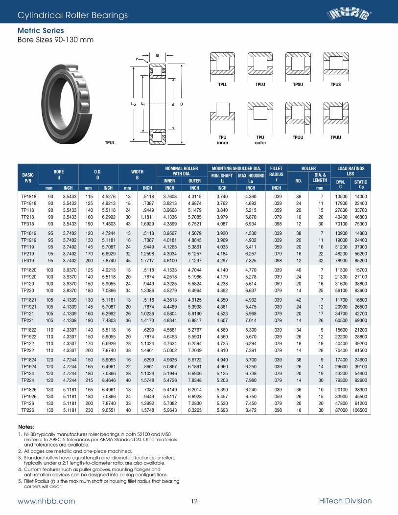
Cylindrical Roller Bearings
Metric SeriesBore sizes 90-130 mm
TP1818 90 3.5433 115 4.5276 13 .5118 3.7603 4.3115 3.740 4.360 .039 36 7 10500 14000 TP1918 90 3.5433 125 4.9213 18 .7087 3.8213 4.6874 3.762 4.693 .039 24 11 17900 22400 TP118 90 3.5433 140 5.5118 24 .9449 3.9668 5.1479 3.840 5.215 .059 20 15 27800 33700 TP218 90 3.5433 160 6.2992 30 1.1811 4.1336 5.7085 3.979 5.870 .079 16 20 40400 46800 TP318 90 3.5433 190 7.4803 43 1.6929 4.3899 6.7521 4.087 6.934 .098 12 30 70100 75300
TP1819 95 3.7402 120 4.7244 13 .5118 3.9567 4.5079 3.920 4.530 .039 38 7 10900 14800 TP1919 95 3.7402 130 5.1181 18 .7087 4.0181 4.8843 3.969 4.902 .039 26 11 19000 24400 TP119 95 3.7402 145 5.7087 24 .9449 4.1263 5.3861 4.033 5.411 .059 20 16 31200 37900 TP219 95 3.7402 170 6.6929 32 1.2598 4.3934 6.1257 4.184 6.257 .079 16 22 48200 56200 TP319 95 3.7402 200 7.8740 45 1.7717 4.6100 7.1297 4.297 7.325 .098 12 32 78900 85200
TP1820 100 3.9370 125 4.9213 13 .5118 4.1533 4.7044 4.140 4.770 .039 40 7 11300 15700 TP1920 100 3.9370 140 5.5118 20 .7874 4.2518 5.1966 4.179 5.278 .039 24 12 21300 27100 TP120 100 3.9370 150 5.9055 24 .9449 4.3225 5.5824 4.238 5.614 .059 20 16 31600 38800 TP220 100 3.9370 180 7.0866 34 1.3386 4.5279 6.4964 4.392 6.637 .079 14 25 56100 63600
TP1821 105 4.1339 130 5.1181 13 .5118 4.3613 4.9125 4.350 4.932 .039 42 7 11700 16500 TP1921 105 4.1339 145 5.7087 20 .7874 4.4489 5.3938 4.361 5.475 .039 24 12 20900 26500 TP121 105 4.1339 160 6.2992 26 1.0236 4.5804 5.9190 4.523 5.968 .079 20 17 34700 42700 TP221 105 4.1339 190 7.4803 36 1.4173 4.8344 6.8817 4.607 7.014 .079 14 26 60500 69300
TP1822 110 4.3307 140 5.5118 16 .6299 4.5681 5.2767 4.560 5.300 .039 34 9 15600 21200 TP1922 110 4.3307 150 5.9055 20 .7874 4.6453 5.5901 4.560 5.670 .039 26 12 22200 28800 TP122 110 4.3307 170 6.6929 28 1.1024 4.7634 6.2594 4.725 6.294 .079 18 19 40400 49200 TP222 110 4.3307 200 7.8740 38 1.4961 5.0002 7.2049 4.810 7.391 .079 14 28 70400 81500
TP1824 120 4.7244 150 5.9055 16 .6299 4.9636 5.6722 4.940 5.700 .039 38 9 17400 24600 TP1924 120 4.7244 165 6.4961 22 .8661 5.0867 6.1891 4.960 6.250 .039 26 14 29600 39100 TP124 120 4.7244 180 7.0866 28 1.1024 5.1946 6.6906 5.125 6.738 .079 20 19 43200 54400 TP224 120 4.7244 215 8.4646 40 1.5748 5.4726 7.8348 5.203 7.980 .079 14 30 79300 92600
TP1826 130 5.1181 165 6.4961 18 .7087 5.4140 6.2014 5.390 6.240 .039 36 10 20100 38300 TP1926 130 5.1181 180 7.0866 24 .9449 5.5117 6.6928 5.457 6.750 .059 26 15 33900 45500 TP126 130 5.1181 200 7.8740 33 1.2992 5.7082 7.2830 5.530 7.450 .079 20 20 47800 61200 TP226 130 5.1181 230 9.0551 40 1.5748 5.9643 8.3265 5.693 8.472 .098 16 30 87000 106500
Notes:1. nHBB typically manufactures roller bearings in both 52100 and M50
material to ABEC 5 tolerances per ABMA standard 20. other materials and tolerances are available.
2. All cages are metallic and one-piece machined.3. standard rollers have equal length and diameter. Rectangular rollers,
typically under a 2:1 length-to-diameter ratio, are also available.4. Custom features such as puller grooves, mounting flanges and
anti-rotation devices can be designed into all ring configurations.5. Fillet Radius (r) is the maximum shaft or housing fillet radius that bearing
corners will clear.
NOMINAL ROLLER MOUNTING SHOULDER DIA. FILLET ROLLER LOAD RATINGS BASIC
BORE O.D. WIDTH PATH DIA. MIN. SHAFT MAX. HOUSING RADIUS DIA. & LBS
P/N d D B
INNER OUTER Li Lo r NO. LENGTH DYN. STATIC mm INCH mm INCH mm INCH INCH INCH INCH INCH INCH mm C Co
B
Lo Li
r
d D
TPLL
TPU inner
TPLU
TPU outer
TPSU
TPUU
TPUU
TPUS
TPUL

www.nhbb.com 13 HiTech Division
Cylindrical Roller Bearings
Metric SeriesBore sizes 140-200 mm
TP1828 140 5.5118 175 6.8898 18 .7087 5.8072 6.5946 5.760 6.630 .039 38 10 22300 32600 TP1928 140 5.5118 190 7.4803 24 .9449 5.9057 7.0868 5.840 7.140 .059 28 15 36400 50300 TP128 140 5.5118 210 8.2677 33 1.2992 6.1027 7.6775 5.939 7.845 .079 22 20 53100 70800 TP228 140 5.5118 250 9.8425 42 1.6535 6.4176 8.9373 6.132 9.220 .098 16 32 99300 123500
TP1830 150 5.9055 190 7.4803 20 .7874 6.1811 7.2047 6.150 7.244 .039 34 13 32300 46700 TP1930 150 5.9055 210 8.2677 28 1.1024 6.4177 7.7563 6.340 7.825 .079 28 17 46400 65400 TP130 150 5.9055 225 8.8583 35 1.3780 6.5150 8.2479 6.435 8.310 .079 22 22 63800 86100
TP1832 160 6.2992 200 7.8740 20 .7874 6.5748 7.5984 6.530 7.618 .039 34 13 32300 46900 TP1932 160 6.2992 220 8.6614 28 1.1024 6.7710 8.1884 6.720 8.270 .079 28 18 51900 73800 TP132 160 6.2992 240 9.4488 38 1.4961 6.9290 8.8187 6.875 8.880 .079 22 24 74000 105000
TP1834 170 6.6929 215 8.4646 22 .8661 7.0669 8.0905 6.980 8.170 .039 36 13 33700 49900 TP1934 170 6.6929 230 9.0551 28 1.1024 7.1650 8.5824 7.070 8.670 .079 28 18 51900 74100 TP134 170 6.6929 260 10.2362 42 1.6535 7.4407 9.4880 7.380 9.590 .079 22 26 86400 119000
TP1836 180 7.0866 225 8.8583 22 .8661 7.4606 8.4826 7.410 8.540 .039 38 13 35100 52900 TP1936 180 7.0866 250 9.8425 33 1.2992 7.6779 9.2527 7.600 9.350 .079 28 20 63600 92200 TP136 180 7.0866 280 11.0236 46 1.8110 7.8742 10.2364 7.820 10.360 .079 20 30 104500 141500
TP1838 190 7.4803 240 9.4488 24 .9449 7.9134 9.0517 7.840 9.150 .059 36 14 38400 57400 TP1938 190 7.4803 260 10.2362 33 1.2992 8.0703 9.6451 8.030 9.770 .079 28 20 63600 92700 TP138 190 7.4803 290 11.4173 46 1.8110 8.2085 10.7085 8.150 10.830 .079 20 32 117500 160000
TP1840 200 7.8740 250 9.8425 24 .9449 8.3071 9.4094 8.220 9.495 .059 38 14 40000 60800 TP1940 200 7.8740 280 11.0236 38 1.4961 8.5057 10.3937 8.415 10.500 .079 26 24 83900 121500
Notes:1. nHBB typically manufactures roller bearings in both 52100 and M50
material to ABEC 5 tolerances per ABMA standard 20. other materials and tolerances are available.
2. All cages are metallic and one-piece machined.3. standard rollers have equal length and diameter. Rectangular rollers,
typically under a 2:1 length-to-diameter ratio, are also available.4. Custom features such as puller grooves, mounting flanges and
anti-rotation devices can be designed into all ring configurations.5. Fillet Radius (r) is the maximum shaft or housing fillet radius that bearing
corners will clear.
NOMINAL ROLLER MOUNTING SHOULDER DIA. FILLET ROLLER LOAD RATINGS BASIC
BORE O.D. WIDTH PATH DIA. MIN. SHAFT MAX. HOUSING RADIUS DIA. & LBS
P/N d D B
INNER OUTER Li Lo r NO. LENGTH DYN. STATIC mm INCH mm INCH mm INCH INCH INCH INCH INCH INCH mm C Co
B
Lo Li
r
d D
TPLL
TPU inner
TPLU
TPU outer
TPSU
TPUU TPUU
TPUS
TPUL

www.nhbb.com 14 HiTech Division

www.nhbb.com 15 HiTech Division
Ball Bearings
Metric Series RadialBore sizes 10-25 mm
LAND DIAMETER FILLET BALL LOAD RATINGS BASIC
BORE O.D. WIDTH (REFERENCE) RADIUS COMPLEMENT LBS
P/N d D B
Li Lo r NO.
SIZE DYN. STATIC mm INCH mm INCH mm INCH INCH INCH INCH INCH C Co
R-1900 10 .3937 22 .8661 6 .2362 .570 .734 .012 9 1/8 580 280 R-100 10 .3937 26 1.0236 8 .3150 .583 .837 .012 7 3/16 1000 440 R-200 10 .3937 30 1.1811 9 .3543 .656 .919 .024 7 7/32 1300 580 R-300 10 .3937 35 1.3780 11 .4331 .717 1.055 .024 6 9/32 1800 770
R-1901 12 .4724 24 .9449 6 .2362 .629 .800 .012 9 9/64 730 350 R-101 12 .4724 28 1.1024 8 .3150 .670 .900 .012 7 3/16 1000 460 R-201 12 .4724 32 1.2598 10 .3937 .725 1.007 .024 7 15/64 1500 670 R-301 12 .4724 37 1.4567 12 .4724 .777 1.153 .039 6 5/16 2150 930
R-1902 15 .5906 28 1.1024 7 .2756 .735 .972 .012 10 5/32 940 490 R-102 15 .5906 32 1.2598 9 .3543 .803 1.048 .012 9 3/16 1250 630 R-202 15 .5906 35 1.3780 11 .4331 .815 1.153 .024 7 1/4 1700 790 R-302 15 .5906 42 1.6535 13 .5118 .934 1.310 .039 7 5/16 2500 1200
R-1903 17 .6693 30 1.1811 7 .2756 .810 1.032 .012 11 5/32 1000 550 R-103 17 .6693 35 1.3780 10 .3937 .910 1.140 .012 10 3/16 1300 710 R-203 17 .6693 40 1.5748 12 .4724 .952 1.292 .024 8 17/64 2100 1050 R-303 17 .6693 47 1.8504 14 .5512 1.017 1.495 .039 7 11/32 3000 1450
R-1804 20 .7874 32 1.2598 7 .2756 .948 1.098 .012 14 1/8 750 480 R-1904 20 .7874 37 1.4567 9 .3543 .995 1.262 .012 9 7/32 1600 860 R-104 20 .7874 42 1.6535 12 .4724 1.075 1.375 .024 8 1/4 1900 990 R-204 20 .7874 47 1.8504 14 .5512 1.131 1.507 .039 8 5/16 2850 1450 R-304 20 .7874 52 2.0472 15 .5906 1.192 1.643 .043 7 3/8 3550 1750
R-1805 25 .9843 37 1.4567 7 .2756 1.145 1.295 .012 17 1/8 820 600 R-1905 25 .9843 42 1.6535 9 .3543 1.195 1.460 .012 11 7/32 1850 1100 R-105 25 .9843 47 1.8504 12 .4724 1.267 1.567 .024 10 1/4 2200 1300 R-205 25 .9843 52 2.0472 15 .5906 1.328 1.703 .039 9 5/16 3100 1750 R-305 25 .9843 62 2.4409 17 .6693 1.450 1.976 .039 7 15/32 4750 2450
Notes:1. Metric series radial ball bearings are typically manufactured from 52100
chrome steel to ABEC 3, 5 and 7 tolerances per ABMA standard 20. 2. Fillet Radius (r) is the maximum shaft or housing fillet radius that bearing
corners will clear.
Br
d DLo Li

www.nhbb.com 16 HiTech Division
Ball Bearings
Metric Series RadialBore sizes 30-55 mm
LAND DIAMETER FILLET BALL LOAD RATINGS BASIC
BORE O.D. WIDTH (REFERENCE) RADIUS COMPLEMENT LBS
P/N d D B
Li Lo r NO.
SIZE DYN. STATIC mm INCH mm INCH mm INCH INCH INCH INCH INCH C Co
R-1806 30 1.1811 42 1.6535 7 .2756 1.342 1.492 .012 20 1/8 880 700 R-1906 30 1.1811 47 1.8504 9 .3543 1.384 1.649 .012 13 7/32 2050 1350 R-106 30 1.1811 55 2.1654 13 .5118 1.504 1.842 .039 11 9/32 2900 1850 R-206 30 1.1811 62 2.4409 16 .6299 1.585 2.037 .039 9 3/8 4350 2500 R-306 30 1.1811 72 2.8346 19 .7480 1.707 2.308 .043 8 1/2 6600 3700
R-1807 35 1.3780 47 1.8504 7 .2756 1.539 1.689 .012 22 1/8 910 760 R-1907 35 1.3780 55 2.1654 10 .3937 1.665 1.942 .024 13 1/4 2600 1750 R-107 35 1.3780 62 2.4409 14 .5512 1.721 2.097 .039 11 5/16 3550 2300 R-207 35 1.3780 72 2.8346 17 .6693 1.824 2.388 .043 8 15/32 5950 3400 R-307 35 1.3780 80 3.1496 21 .8268 1.925 2.602 .059 8 9/16 8200 4700
R-1808 40 1.5748 52 2.0472 7 .2756 1.735 1.886 .012 25 1/8 970 860 R-1908 40 1.5748 62 2.4409 12 .4724 1.857 2.158 .024 14 1/4 2550 1800 R-108 40 1.5748 68 2.6772 15 .5906 1.900 2.351 .039 10 3/8 4650 2950 R-208 40 1.5748 80 3.1496 18 .7087 2.061 2.663 .043 9 1/2 7250 4450 R-308 40 1.5748 90 3.5433 23 .9055 2.183 2.935 .059 8 5/8 9900 5850
R-1809 45 1.7717 58 2.2835 7 .2756 1.953 2.103 .012 28 1/8 1000 950 R-1909 45 1.7717 68 2.6772 12 .4724 2.055 2.393 .024 15 9/32 3450 2650 R-109 45 1.7717 75 2.9528 16 .6299 2.136 2.587 .039 12 3/8 5200 3600 R-209 45 1.7717 85 3.3465 19 .7480 2.277 2.841 .043 9 1/2 7275 4525 R-309 45 1.7717 100 3.9370 25 .9843 2.440 3.268 .059 8 11/16 11800 7100
R-1810 50 1.9685 65 2.5591 7 .2756 2.169 2.357 .012 25 5/32 1400 1295 R-1910 50 1.9685 72 2.8346 12 .4724 2.232 2.570 .024 16 9/32 3600 2850 R-110 50 1.9685 80 3.1496 16 .6299 2.333 2.784 .039 13 3/8 5450 4000 R-210 50 1.9685 90 3.5433 20 .7874 2.455 3.056 .043 10 1/2 7800 5200 R-310 50 1.9685 110 4.3307 27 1.0630 2.698 3.600 .079 8 3/4 13800 8500
R-1811 55 2.1654 72 2.8346 9 .3543 2.387 2.612 .012 23 3/16 1950 1850 R-1911 55 2.1654 80 3.1496 13 .5118 2.469 2.845 .039 16 5/16 4350 3550 R-111 55 2.1654 90 3.5433 18 .7087 2.591 3.117 .043 12 7/16 6900 4950 R-211 55 2.1654 100 3.9370 21 .8268 2.712 3.389 .059 10 9/16 9650 6550 R-311 55 2.1654 120 4.7244 29 1.1417 2.956 3.933 .079 8 13/16 16000 10000
Notes:1. Metric series radial ball bearings are typically manufactured from 52100
chrome steel to ABEC 3, 5 and 7 tolerances per ABMA standard 20. 2. Fillet Radius (r) is the maximum shaft or housing fillet radius that bearing
corners will clear.
Br
d DLo Li

www.nhbb.com 17 HiTech Division
Ball Bearings
Metric Series RadialBore sizes 60-85 mm
LAND DIAMETER FILLET BALL LOAD RATINGS BASIC
BORE O.D. WIDTH (REFERENCE) RADIUS COMPLEMENT LBS
P/N d D B
Li Lo r NO.
SIZE DYN. STATIC mm INCH mm INCH mm INCH INCH INCH INCH INCH C Co
R-1812 60 2.3622 78 3.0709 10 .3937 2.584 2.848 .012 22 7/32 2600 2400 R-1912 60 2.3622 85 3.3465 13 .5118 2.666 3.042 .039 17 5/16 4500 3800 R-112 60 2.3622 95 3.7402 18 .7087 2.788 3.314 .043 12 7/16 6800 5050 R-212 60 2.3622 110 4.3307 22 .8661 2.970 3.722 .059 10 5/8 11700 8050 R-312 60 2.3622 130 5.1181 31 1.2205 3.213 4.266 .083 8 7/8 18300 11100
R-1813 65 2.5591 85 3.3465 10 .3937 2.821 3.084 .024 23 7/32 2600 2500 R-1913 65 2.5591 90 3.5433 13 .5118 2.863 3.239 .039 18 5/16 4600 4100 R-113 65 2.5591 100 3.9370 18 .7087 2.985 3.511 .043 13 7/16 7100 5550 R-213 65 2.5591 120 4.7244 23 .9055 3.228 4.055 .059 10 11/16 13900 9700 R-313 65 2.5591 140 5.5118 33 1.2992 3.471 4.599 .083 8 15/16 20700 13500
R-1814 70 2.7559 90 3.5433 10 .3937 3.018 3.281 .024 25 7/32 2700 2700 R-1914 70 2.7559 100 3.9370 16 .6299 3.139 3.553 .039 17 11/32 5250 4650 R-114 70 2.7559 110 4.3307 20 .7874 3.242 3.844 .043 13 1/2 9150 7200 R-214 70 2.7559 125 4.9213 24 .9449 3.424 4.252 .059 10 11/16 13900 9850 R-314 70 2.7559 150 5.9055 35 1.3780 3.729 4.932 .083 8 1 23300 15400
R-1815 75 2.9528 95 3.7402 10 .3937 3.214 3.478 .024 26 7/32 2750 2800 R-1915 75 2.9528 105 4.1339 16 .6299 3.317 3.768 .039 17 3/8 5550 6200 R-115 75 2.9528 115 4.5276 20 .7874 3.440 4.041 .043 14 1/2 7800 9500 R-215 75 2.9528 130 5.1181 25 .9843 3.621 4.449 .059 10 11/16 10000 13900 R-315 75 2.9528 160 6.2992 37 1.4567 3.986 5.265 .083 8 1-1/16 17400 26000
R-1816 80 3.1496 100 3.9370 10 .3937 3.411 3.674 .024 28 7/32 2850 3000 R-1916 80 3.1496 110 4.3307 16 .6299 3.514 3.965 .039 17 3/8 5600 6100 R-116 80 3.1496 125 4.9213 22 .8661 3.697 4.373 .043 13 9/16 9100 11300 R-216 80 3.1496 140 5.5118 26 1.0236 3.879 4.782 .079 10 3/4 11900 16200 R-316 80 3.1496 170 6.6929 39 1.5354 4.244 5.598 .083 8 1-1/8 19500 28800
R-1817 85 3.3465 110 4.3307 13 .5118 3.669 4.007 .039 24 9/32 4200 4300 R-1917 85 3.3465 120 4.7244 18 .7087 3.772 4.298 .043 16 7/16 7800 6950 R-117 85 3.3465 130 5.1181 22 .8661 3.893 4.570 .043 13 9/16 11000 9050 R-217 85 3.3465 150 5.9055 28 1.1024 4.137 5.114 .079 10 13/16 18400 13600 R-317 85 3.3465 180 7.0866 41 1.6142 4.539 5.893 .118 8 1-1/8 28500 19600
Notes:1. Metric series radial ball bearings are typically manufactured from 52100
chrome steel to ABEC 3, 5 and 7 tolerances per ABMA standard 20. 2. Fillet Radius (r) is the maximum shaft or housing fillet radius that bearing
corners will clear.
Br
d DLo Li

www.nhbb.com 18 HiTech Division
Ball Bearings
Metric Series RadialBore sizes 90-130 mm
LAND DIAMETER FILLET BALL LOAD RATINGS BASIC
BORE O.D. WIDTH (REFERENCE) RADIUS COMPLEMENT LBS
P/N d D B
Li Lo r NO.
SIZE DYN. STATIC mm INCH mm INCH mm INCH INCH INCH INCH INCH C Co
R-1818 90 3.5433 115 4.5276 13 .5118 3.866 4.204 .039 25 9/32 4250 4450 R-1918 90 3.5433 125 4.9213 18 .7087 3.969 4.495 .043 17 7/16 8000 7450 R-118 90 3.5433 140 5.5118 24 .9449 4.151 4.903 .059 13 5/8 13300 11100 R-218 90 3.5433 160 6.2992 30 1.1811 4.394 5.447 .079 10 7/8 21000 15700 R-318 90 3.5433 190 7.4803 43 1.6929 4.797 6.226 .118 8 1-3/16 31400 21800
R-1819 95 3.7402 120 4.7244 13 .5118 4.063 4.401 .039 26 9/32 4350 4650 R-1919 95 3.7402 130 5.1181 18 .7087 4.165 4.692 .043 18 7/16 8400 8100 R-119 95 3.7402 145 5.7087 24 .9449 4.348 5.100 .059 13 5/8 13500 11400 R-219 95 3.7402 170 6.6929 32 1.2598 4.652 5.780 .083 10 15/16 24300 18400 R-319 95 3.7402 200 7.8740 45 1.7717 5.055 6.559 .118 8 1-1/4 35100 24700
R-1820 100 3.9370 125 4.9213 13 .5118 4.259 4.598 .039 27 9/32 4450 4850 R-1920 100 3.9370 140 5.5118 20 .7874 4.423 5.025 .043 17 1/2 10500 9900 R-120 100 3.9370 150 5.9055 24 .9449 4.545 5.297 .059 14 5/8 14100 12400 R-220 100 3.9370 180 7.0866 34 1.3386 4.910 6.113 .083 10 1 27300 20900
R-1821 105 4.1339 130 5.1181 13 .5118 4.456 4.795 .039 28 9/32 4500 5000 R-1921 105 4.1339 145 5.7087 20 .7874 4.620 5.222 .043 17 1/2 10400 9950 R-121 105 4.1339 160 6.2992 26 1.0236 4.802 5.630 .079 13 11/16 16100 13800 R-221 105 4.1339 190 7.4803 36 1.4173 5.167 6.446 .083 10 1-1/16 30500 23500
R-1822 110 4.3307 140 5.5118 16 .6299 4.714 5.128 .039 25 11/32 6200 6800 R-1922 110 4.3307 150 5.9055 20 .7874 4.817 5.418 .043 18 1/2 10700 10600 R-122 110 4.3307 170 6.6929 28 1.1024 5.060 5.963 .079 13 3/4 18900 16300 R-222 110 4.3307 200 7.8740 38 1.4961 5.425 6.779 .079 10 1-1/8 33900 26300
R-1824 120 4.7244 150 5.9055 16 .6299 5.108 5.521 .039 27 11/32 6450 7300 R-1924 120 4.7244 165 6.4961 22 .8661 5.273 5.947 .043 17 9/16 12800 12700 R-124 120 4.7244 180 7.0866 28 1.1024 5.454 6.356 .079 14 3/4 19700 17900 R-224 120 4.7244 215 8.4646 40 1.5748 5.917 7.271 .079 10 1-1/8 33700 26900
R-1826 130 5.1181 165 6.4961 18 .7087 5.563 6.052 .043 25 13/32 8400 9500 R-1926 130 5.1181 180 7.0866 24 .9449 5.726 6.478 .059 17 5/8 15600 15600 R-126 130 5.1181 200 7.8740 33 1.2992 5.971 7.023 .079 13 7/8 25000 22300 R-226 130 5.1181 230 9.0551 40 1.5748 6.372 7.801 .098 10 1-3/16 37200 30100
Notes:1. Metric series radial ball bearings are typically manufactured from 52100
chrome steel to ABEC 3, 5 and 7 tolerances per ABMA standard 20. 2. Fillet Radius (r) is the maximum shaft or housing fillet radius that bearing
corners will clear.
Br
d DLo Li

www.nhbb.com 19 HiTech Division
Ball Bearings
Metric Series RadialBore sizes 140-200 mm
LAND DIAMETER FILLET BALL LOAD RATINGS BASIC
BORE O.D. WIDTH (REFERENCE) RADIUS COMPLEMENT LBS
P/N d D B
Li Lo r NO.
SIZE DYN. STATIC mm INCH mm INCH mm INCH INCH INCH INCH INCH C Co
R-1828 140 5.5118 175 6.8898 18 .7087 5.956 6.445 .043 26 13/32 8500 9800 R-1928 140 5.5118 190 7.4803 24 .9449 5.923 6.675 .059 18 5/8 16000 16500 R-128 140 5.5118 210 8.2677 33 1.2992 6.363 7.416 .079 14 7/8 26000 24300 R-228 140 5.5118 250 9.8425 42 1.6535 6.887 8.467 .098 10 1-5/16 44600 36600
R-1830 150 5.9055 190 7.4803 20 .7874 6.430 6.956 .043 26 7/16 9700 11400 R-1930 150 5.9055 210 8.2677 28 1.1024 6.635 7.538 .079 16 3/4 20900 21000 R-130 150 5.9055 225 8.8583 35 1.3780 6.855 7.908 .083 15 7/8 26900 36400
R-1832 160 6.2992 200 7.8740 20 .7874 6.823 7.350 .043 28 7/16 10000 12200 R-1932 160 6.2992 220 8.6614 28 1.1024 7.029 7.932 .079 17 3/4 21500 22500 R-132 160 6.2992 240 9.4488 38 1.4961 7.272 8.476 .083 14 1 33100 31800
R-1834 170 6.6929 215 8.4646 22 .8661 7.278 7.880 .043 26 1/2 12400 14900 R-1934 170 6.6929 230 9.0551 28 1.1024 7.423 8.325 .079 18 3/4 22000 24000 R-134 170 6.6929 260 10.2360 42 1.6535 7.788 9.141 .083 13 1-1/8 39200 37000
R-1836 180 7.0866 225 8.8583 22 .8661 7.672 8.273 .043 28 1/2 12800 16000 R-1936 180 7.0866 250 9.8425 33 1.2992 7.938 8.991 .079 17 7/8 28700 30500 R-136 180 7.0866 280 11.0240 46 1.8110 8.378 9.732 .083 14 1-1/8 40800 40400
R-1838 190 7.4803 240 9.4488 24 .9449 8.126 8.803 .059 26 9/16 15400 18900 R-1938 190 7.4803 260 10.2360 33 1.2992 8.332 9.385 .079 17 7/8 28300 30700 R-138 190 7.4803 290 11.4173 46 1.8110 8.734 10.163 .083 14 1-3/16 45500 44400
R-1840 200 7.8740 250 9.8425 24 .9449 8.520 9.197 .059 27 9/16 15600 19500 R-1940 200 7.8740 280 11.0240 38 1.4961 8.847 10.050 .083 16 1 35200 37400
Notes:1. Metric series radial ball bearings are typically manufactured from 52100
chrome steel to ABEC 3, 5 and 7 tolerances per ABMA standard 20. 2. Fillet Radius (r) is the maximum shaft or housing fillet radius that bearing
corners will clear.
Br
d DLo Li
www.nhbb.com 20 HiTech Division
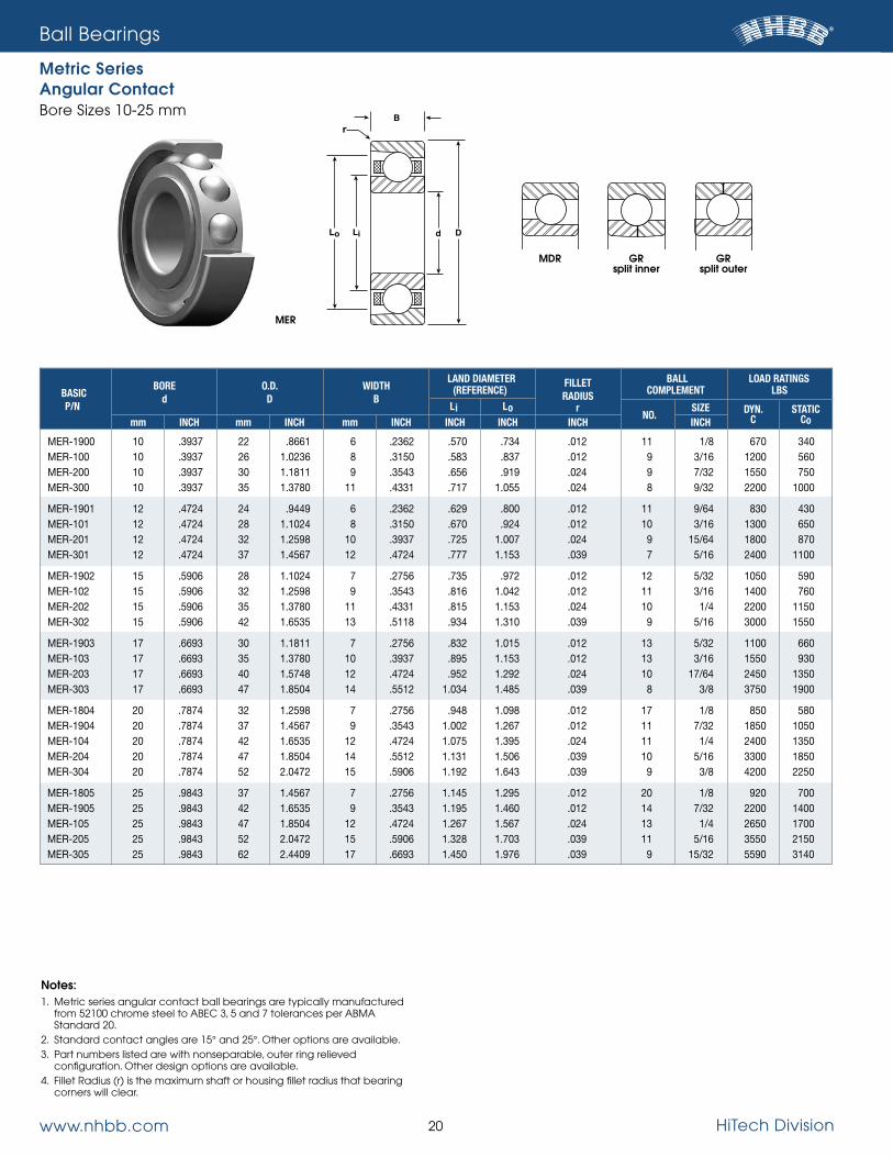
Ball Bearings
Metric Series Angular ContactBore sizes 10-25 mm
Notes:1. Metric series angular contact ball bearings are typically manufactured
from 52100 chrome steel to ABEC 3, 5 and 7 tolerances per ABMA standard 20.
2. standard contact angles are 15° and 25°. other options are available.3. Part numbers listed are with nonseparable, outer ring relieved
configuration. other design options are available.4. Fillet Radius (r) is the maximum shaft or housing fillet radius that bearing
corners will clear.
LAND DIAMETER FILLET BALL LOAD RATINGS BASIC
BORE O.D. WIDTH (REFERENCE) RADIUS COMPLEMENT LBS
P/N d D B
Li Lo r NO.
SIZE DYN. STATIC mm INCH mm INCH mm INCH INCH INCH INCH INCH C Co
MER-1900 10 .3937 22 .8661 6 .2362 .570 .734 .012 11 1/8 670 340 MER-100 10 .3937 26 1.0236 8 .3150 .583 .837 .012 9 3/16 1200 560 MER-200 10 .3937 30 1.1811 9 .3543 .656 .919 .024 9 7/32 1550 750 MER-300 10 .3937 35 1.3780 11 .4331 .717 1.055 .024 8 9/32 2200 1000
MER-1901 12 .4724 24 .9449 6 .2362 .629 .800 .012 11 9/64 830 430 MER-101 12 .4724 28 1.1024 8 .3150 .670 .924 .012 10 3/16 1300 650 MER-201 12 .4724 32 1.2598 10 .3937 .725 1.007 .024 9 15/64 1800 870 MER-301 12 .4724 37 1.4567 12 .4724 .777 1.153 .039 7 5/16 2400 1100
MER-1902 15 .5906 28 1.1024 7 .2756 .735 .972 .012 12 5/32 1050 590 MER-102 15 .5906 32 1.2598 9 .3543 .816 1.042 .012 11 3/16 1400 760 MER-202 15 .5906 35 1.3780 11 .4331 .815 1.153 .024 10 1/4 2200 1150 MER-302 15 .5906 42 1.6535 13 .5118 .934 1.310 .039 9 5/16 3000 1550
MER-1903 17 .6693 30 1.1811 7 .2756 .832 1.015 .012 13 5/32 1100 660 MER-103 17 .6693 35 1.3780 10 .3937 .895 1.153 .012 13 3/16 1550 930 MER-203 17 .6693 40 1.5748 12 .4724 .952 1.292 .024 10 17/64 2450 1350 MER-303 17 .6693 47 1.8504 14 .5512 1.034 1.485 .039 8 3/8 3750 1900
MER-1804 20 .7874 32 1.2598 7 .2756 .948 1.098 .012 17 1/8 850 580 MER-1904 20 .7874 37 1.4567 9 .3543 1.002 1.267 .012 11 7/32 1850 1050 MER-104 20 .7874 42 1.6535 12 .4724 1.075 1.395 .024 11 1/4 2400 1350 MER-204 20 .7874 47 1.8504 14 .5512 1.131 1.506 .039 10 5/16 3300 1850 MER-304 20 .7874 52 2.0472 15 .5906 1.192 1.643 .039 9 3/8 4200 2250
MER-1805 25 .9843 37 1.4567 7 .2756 1.145 1.295 .012 20 1/8 920 700 MER-1905 25 .9843 42 1.6535 9 .3543 1.195 1.460 .012 14 7/32 2200 1400 MER-105 25 .9843 47 1.8504 12 .4724 1.267 1.567 .024 13 1/4 2650 1700 MER-205 25 .9843 52 2.0472 15 .5906 1.328 1.703 .039 11 5/16 3550 2150 MER-305 25 .9843 62 2.4409 17 .6693 1.450 1.976 .039 9 15/32 5590 3140
GR split outer
GR split inner
MDR
Lo Li d D
Br
MER

www.nhbb.com 21 HiTech Division
Ball Bearings
Metric Series Angular ContactBore sizes 30-55 mm
Notes:1. Metric series angular contact ball bearings are typically manufactured
from 52100 chrome steel to ABEC 3, 5 and 7 tolerances per ABMA standard 20.
2. standard contact angles are 15° and 25°. other options are available.3. Part numbers listed are with nonseparable, outer ring relieved
configuration. other design options are available.4. Fillet Radius (r) is the maximum shaft or housing fillet radius that bearing
corners will clear.
LAND DIAMETER FILLET BALL LOAD RATINGS BASIC
BORE O.D. WIDTH (REFERENCE) RADIUS COMPLEMENT LBS
P/N d D B
Li Lo r NO.
SIZE DYN. STATIC mm INCH mm INCH mm INCH INCH INCH INCH INCH C Co
MER-1806 30 1.1811 42 1.6535 7 .2756 1.342 1.492 .012 23 1/8 970 810 MER-1906 30 1.1811 47 1.8504 9 .3543 1.384 1.649 .012 16 7/32 2350 1650 MER-106 30 1.1811 55 2.1654 13 .5118 1.504 1.842 .039 14 9/32 3450 2350 MER-206 30 1.1811 62 2.4409 16 .6299 1.585 2.045 .039 12 3/8 5250 3350 MER-306 30 1.1811 72 2.8346 19 .7480 1.707 2.308 .039 10 1/2 7700 4650
MER-1807 35 1.3780 47 1.8504 7 .2756 1.539 1.689 .012 26 1/8 1000 900 MER-1907 35 1.3780 55 2.1654 10 .3937 1.644 1.942 .024 18 1/4 3200 2450 MER-107 35 1.3780 62 2.4409 14 .5512 1.721 2.097 .039 15 5/16 4350 3100 MER-207 35 1.3780 72 2.8346 17 .6693 1.825 2.388 .039 10 15/32 6900 4250 MER-307 35 1.3780 80 3.1496 21 .8268 1.926 2.602 .059 10 9/16 9500 5850
MER-1808 40 1.5748 52 2.0472 7 .2756 1.735 1.886 .012 29 1/8 1050 1000 MER-1908 40 1.5748 62 2.4409 12 .4724 1.878 2.141 .024 19 1/4 3250 2700 MER-108 40 1.5748 68 2.6772 15 .5906 1.900 2.351 .039 14 3/8 5800 4100 MER-208 40 1.5748 80 3.1496 18 .7087 2.062 2.663 .039 11 1/2 8300 5450 MER-308 40 1.5748 90 3.5433 23 .9055 2.184 2.935 .059 10 5/8 11500 7300
MER-1809 45 1.7717 58 2.2835 7 .2756 1.952 2.102 .012 31 1/8 1100 1050 MER-1909 45 1.7717 68 2.6772 12 .4724 2.055 2.394 .024 19 9/32 4050 3350 MER-109 45 1.7717 75 2.9528 16 .6299 2.137 2.588 .039 15 3/8 6050 4500 MER-209 45 1.7717 85 3.3465 19 .7480 2.258 2.859 .039 13 15/32 9295 6540 MER-309 45 1.7717 100 3.9370 25 .9843 2.441 3.267 .059 11 11/16 14600 9800
MER-1810 50 1.9685 65 2.5591 7 .2756 2.169 2.357 .012 30 5/32 1585 1560 MER-1910 50 1.9685 72 2.8346 12 .4724 2.232 2.571 .024 21 9/32 4300 3750 MER-110 50 1.9685 80 3.1496 16 .6299 2.334 2.785 .039 18 3/8 6675 5450 MER-210 50 1.9685 90 3.5433 20 .7874 2.455 3.056 .039 14 1/2 9800 7250 MER-310 50 1.9685 110 4.3307 27 1.0630 2.699 3.600 .079 11 3/4 17100 11700
MER-1811 55 2.1654 72 2.8346 9 .3543 2.387 2.612 .012 29 3/16 2300 2300 MER-1911 55 2.1654 80 3.1496 13 .5118 2.469 2.845 .039 20 5/16 5050 4450 MER-111 55 2.1654 90 3.5433 18 .7087 2.592 3.116 .039 17 7/16 8700 7050 MER-211 55 2.1654 100 3.9370 21 .8268 2.713 3.389 .059 14 9/16 12100 9150 MER-311 55 2.1654 120 4.7244 29 1.1417 2.956 3.933 .079 11 13/16 19800 13800
GR split outer
GR split inner
MDR
Lo Li d D
Br
MER

www.nhbb.com 22 HiTech Division
Ball Bearings
Metric Series Angular ContactBore sizes 60-85 mm
Notes:1. Metric series angular contact ball bearings are typically manufactured
from 52100 chrome steel to ABEC 3, 5 and 7 tolerances per ABMA standard 20.
2. standard contact angles are 15° and 25°. other options are available.3. Part numbers listed are with nonseparable, outer ring relieved
configuration. other design options are available.4. Fillet Radius (r) is the maximum shaft or housing fillet radius that bearing
corners will clear.
LAND DIAMETER FILLET BALL LOAD RATINGS BASIC
BORE O.D. WIDTH (REFERENCE) RADIUS COMPLEMENT LBS
P/N d D B
Li Lo r NO.
SIZE DYN. STATIC mm INCH mm INCH mm INCH INCH INCH INCH INCH C Co
MER-1812 60 2.3622 78 3.0709 10 .3937 2.584 2.848 .012 28 7/32 3050 3050 MER-1912 60 2.3622 85 3.3465 13 .5118 2.666 3.042 .039 21 5/16 5150 4700 MER-112 60 2.3622 95 3.7402 18 .7087 2.788 3.314 .039 18 7/16 8950 7600 MER-212 60 2.3622 110 4.3307 22 .8661 2.971 3.722 .059 14 5/8 14700 11300 MER-312 60 2.3622 130 5.1181 31 1.2205 3.213 4.266 .079 11 7/8 22600 16100
MER-1813 65 2.5591 85 3.3465 10 .3937 2.821 3.084 .024 29 7/32 3050 3150 MER-1913 65 2.5591 90 3.5433 13 .5118 2.863 3.239 .039 23 5/16 5450 5200 MER-113 65 2.5591 100 3.9370 18 .7087 2.985 3.511 .039 19 7/16 9150 8100 MER-213 65 2.5591 120 4.7244 23 .9055 3.228 4.055 .059 14 11/16 17400 13600 MER-313 65 2.5591 140 5.5118 33 1.2992 3.471 4.599 .079 12 15/16 27200 20200
MER-1814 70 2.7559 90 3.5433 10 .3937 3.018 3.281 .024 31 7/32 3150 3350 MER-1914 70 2.7559 100 3.9370 16 .6299 3.139 3.553 .039 21 11/32 6100 5750 MER-114 70 2.7559 110 4.3307 20 .7874 3.243 3.844 .039 18 1/2 11300 9950 MER-214 70 2.7559 125 4.9213 24 .9449 3.424 4.252 .059 15 11/16 18200 14800 MER-314 70 2.7559 150 5.9055 35 1.3780 3.729 4.932 .079 12 1 30500 23000
MER-1815 75 2.9528 95 3.7402 10 .3937 3.214 3.478 .024 33 7/32 3200 3550 MER-1915 75 2.9528 105 4.1339 16 .6299 3.318 3.769 .039 26 3/8 8250 8500 MER-115 75 2.9528 115 4.5276 20 .7874 3.440 4.041 .039 20 1/2 12100 11200 MER-215 75 2.9528 130 5.1181 25 .9843 3.621 4.449 .059 16 11/16 19000 16000 MER-315 75 2.9528 160 6.2992 37 1.4567 3.986 5.265 .079 12 1-1/16 34100 26100
MER-1816 80 3.1496 100 3.9370 10 .3937 3.411 3.675 .024 35 7/32 3300 3750 MER-1916 80 3.1496 110 4.3307 16 .6299 3.515 3.966 .039 27 3/8 8350 8850 MER-116 80 3.1496 125 4.9213 22 .8661 3.809 4.261 .039 19 9/16 14500 13300 MER-216 80 3.1496 140 5.5118 26 1.0236 3.992 4.669 .079 16 3/4 22200 19000 MER-316 80 3.1496 170 6.6929 39 1.5354 4.470 5.372 .079 12 1-1/8 37800 29300
MER-1817 85 3.3465 110 4.3307 13 .5118 3.669 4.007 .039 30 9/32 4900 5450 MER-1917 85 3.3465 120 4.7244 18 .7087 3.772 4.298 .039 25 7/16 10700 11100 MER-117 85 3.3465 130 5.1181 22 .8661 3.893 4.570 .039 20 9/16 14900 14200 MER-217 85 3.3465 150 5.9055 28 1.1024 4.137 5.114 .079 15 13/16 24600 20800 MER-317 85 3.3465 180 7.0866 41 1.6142 4.539 5.893 .098 13 1-1/8 40100 32400
GR split outer
GR split inner
MDR
Lo Li d D
Br
MER

www.nhbb.com 23 HiTech Division
Ball Bearings
Metric Series Angular ContactBore sizes 90-130 mm
Notes:1. Metric series angular contact ball bearings are typically manufactured
from 52100 chrome steel to ABEC 3, 5 and 7 tolerances per ABMA standard 20.
2. standard contact angles are 15° and 25°. other options are available.3. Part numbers listed are with nonseparable, outer ring relieved
configuration. other design options are available.4. Fillet Radius (r) is the maximum shaft or housing fillet radius that bearing
corners will clear.
LAND DIAMETER FILLET BALL LOAD RATINGS BASIC
BORE O.D. WIDTH (REFERENCE) RADIUS COMPLEMENT LBS
P/N d D B
Li Lo r NO.
SIZE DYN. STATIC mm INCH mm INCH mm INCH INCH INCH INCH INCH C Co
MER-1818 90 3.5433 115 4.5276 13 .5118 3.904 4.166 .039 31 9/32 4950 5600 MER-1918 90 3.5433 125 4.9213 18 .7087 3.969 4.495 .039 26 7/16 10900 11600 MER-118 90 3.5433 140 5.5118 24 .9449 4.151 4.903 .059 20 5/8 18200 17400 MER-218 90 3.5433 160 6.2992 30 1.1811 4.394 5.447 .079 15 7/8 28100 24100 MER-318 90 3.5433 190 7.4803 43 1.6929 4.797 6.226 .098 13 1-3/16 44200 36200
MER-1819 95 3.7402 120 4.7244 13 .5118 4.101 4.363 .039 32 9/32 5000 5750 MER-1919 95 3.7402 130 5.1181 18 .7087 4.169 4.692 .039 28 7/16 11300 12600 MER-119 95 3.7402 145 5.7087 24 .9449 4.348 5.100 .059 21 5/8 18600 18400 MER-219 95 3.7402 170 6.6929 32 1.2598 4.652 5.780 .079 15 15/16 31900 27600 MER-319 95 3.7402 200 7.8740 45 1.7717 5.055 6.559 .098 13 1-1/4 48500 40100
MER-1820 100 3.9370 125 4.9213 13 .5118 4.259 4.598 .039 34 9/32 5150 6100 MER-1920 100 3.9370 140 5.5118 20 .7874 4.423 5.025 .039 26 1/2 13900 15100 MER-120 100 3.9370 150 5.9055 24 .9449 4.545 5.297 .059 21 5/8 18500 18600 MER-220 100 3.9370 180 7.0866 34 1.3386 4.910 6.113 .079 15 1 35800 31300
MER-1821 105 4.1339 130 5.1181 13 .5118 4.456 4.795 .039 36 9/32 5300 6400 MER-1921 105 4.1339 145 5.7087 20 .7874 4.620 5.222 .039 27 1/2 14200 15800 MER-121 105 4.1339 160 6.2992 26 1.0236 4.802 5.630 .079 21 11/16 22100 22300 MER-221 105 4.1339 190 7.4803 36 1.4173 5.167 6.446 .079 15 1-1/16 40000 35300
MER-1822 110 4.3307 140 5.5118 16 .6299 4.714 5.128 .039 32 11/32 7300 8650 MER-1922 110 4.3307 150 5.9055 20 .7874 4.817 5.418 .039 28 1/2 14300 16500 MER-122 110 4.3307 170 6.6929 28 1.1024 5.060 5.963 .079 20 3/4 25200 25100 MER-222 110 4.3307 200 7.8740 38 1.4961 5.425 6.779 .079 15 1-1/8 44300 39400
MER-1824 120 4.7244 150 5.9055 16 .6299 5.108 5.521 .039 35 11/32 7600 9400 MER-1924 120 4.7244 165 6.4961 22 .8661 5.271 5.948 .039 27 9/16 17400 20100 MER-124 120 4.7244 180 7.0866 28 1.1024 5.454 6.356 .079 22 3/4 26600 28000 MER-224 120 4.7244 215 8.4646 40 1.5748 5.917 7.271 .079 16 1-1/8 46200 43000
MER-1826 130 5.1181 165 6.4961 18 .7087 5.562 6.051 .039 32 13/32 9900 12100 MER-1926 130 5.1181 180 7.0866 24 .9449 5.726 6.478 .059 27 5/8 21200 24700 MER-126 130 5.1181 200 7.8740 33 1.2992 5.969 7.022 .079 20 7/8 33200 34300 MER-226 130 5.1181 230 9.0551 40 1.5748 6.372 7.801 .098 17 1-3/16 52900 51200
GR split outer
GR split inner
MDR
Lo Li d D
Br
MER

www.nhbb.com 24 HiTech Division
Ball Bearings
Metric Series Angular ContactBore sizes 140-200 mm
Notes:1. Metric series angular contact ball bearings are typically manufactured
from 52100 chrome steel to ABEC 3, 5 and 7 tolerances per ABMA standard 20.
2. standard contact angles are 15° and 25°. other options are available.3. Part numbers listed are with nonseparable, outer ring relieved
configuration. other design options are available.4. Fillet Radius (r) is the maximum shaft or housing fillet radius that bearing
corners will clear.
LAND DIAMETER FILLET BALL LOAD RATINGS BASIC
BORE O.D. WIDTH (REFERENCE) RADIUS COMPLEMENT LBS
P/N d D B
Li Lo r NO.
SIZE DYN. STATIC mm INCH mm INCH mm INCH INCH INCH INCH INCH C Co
MER-1828 140 5.5118 175 6.8898 18 .7087 5.956 6.445 .039 35 13/32 10300 13200 MER-1928 140 5.5118 190 7.4803 24 .9449 5.923 6.675 .059 29 5/8 22000 26700 MER-128 140 5.5118 210 8.2677 33 1.2992 6.363 7.416 .079 22 7/8 35100 38100 MER-228 140 5.5118 250 9.8425 42 1.6535 6.887 8.466 .098 16 1-5/16 61000 58500
MER-1830 150 5.9055 190 7.4803 20 .7874 6.429 6.956 .039 35 7/16 11800 15300 MER-1930 150 5.9055 210 8.2677 28 1.1024 6.635 7.537 .079 26 3/4 28900 34200 MER-130 150 5.9055 225 8.8583 35 1.3780 6.855 7.908 .079 23 7/8 35800 40400
MER-1832 160 6.2992 200 7.8740 20 .7874 6.823 7.349 .039 37 7/16 12100 16100 MER-1932 160 6.2992 220 8.6614 28 1.1024 7.029 7.931 .079 27 3/4 29300 35800 MER-132 160 6.2992 240 9.4488 38 1.4961 7.272 8.475 .079 22 1 44700 49900
MER-1834 170 6.6929 215 8.4646 22 .8661 7.277 7.879 .039 35 1/2 15100 20000 MER-1934 170 6.6929 230 9.0551 28 1.1024 7.422 8.325 .079 29 3/4 30300 38700 MER-134 170 6.6929 260 10.2360 42 1.6535 7.787 9.141 .079 21 1-1/8 54000 59800
MER-1836 180 7.0866 225 8.8583 22 .8661 7.671 8.273 .039 37 1/2 15500 21100 MER-1936 180 7.0866 250 9.8425 33 1.2992 7.938 8.991 .079 27 7/8 39000 48500 MER-136 180 7.0866 280 11.0240 46 1.8110 8.378 9.732 .079 22 1-1/8 55100 63500
MER-1838 190 7.4803 240 9.4488 24 .9449 8.126 8.803 .059 36 9/16 19100 26200 MER-1938 190 7.4803 260 10.2360 33 1.2992 8.331 9.384 .079 28 7/8 39500 50600 MER-138 190 7.4803 290 11.4173 46 1.8110 8.734 10.163 .079 22 1-3/16 60800 70600
MER-1840 200 7.8740 250 9.8425 24 .9449 8.519 9.196 .059 37 9/16 19200 26800 MER-1940 200 7.8740 280 11.0240 38 1.4961 8.847 10.050 .079 26 1 48600 60800
GR split outer
GR split inner
MDR
Lo Li d D
Br
MER

www.nhbb.com 25 HiTech Division
Ball Bearings
Inch Series RadialBore sizes .5000-1.5000 inches
RI-1812 .5000 12.700 1.1250 28.575 .2500 6.350 .3125 7.938 .701 .913 .016 9 5/32 861 434 290
RI-2258 .6250 15.875 1.3750 34.925 .2812 7.142 .3438 8.732 .852 1.132 .031 8 7/32 1518 747 617
RI-2634 .7500 19.050 1.6250 41.275 .3125 7.938 .4375 11.112 1.020 1.344 .031 8 1/4 1886 951 663
RI-3078 .8750 22.225 1.8750 47.625 .3750 9.525 .5000 12.700 1.266 1.567 .031 10 1/4 2255 1316 960
RI-3216 1.0000 25.400 2.0000 50.800 .3750 9.525 .5000 12.700 1.327 1.703 .031 9 5/16 3145 1763 1396
RI-3418 1.1250 28.575 2.1250 53.975 .3750 9.525 .5000 12.700 1.503 1.842 .031 11 9/32 2966 1857 1467
RI-3620 1.2500 31.750 2.2500 57.150 .3750 9.525 .5000 12.700 1.503 1.842 .031 11 9/32 2966 1857 1414
RI-4224 1.5000 38.100 2.6250 66.675 .4375 11.112 .5625 14.288 1.856 2.269 .031 11 11/32 4258 2786 2238
Open
Shielded
Lo Li d D
Br
Notes:1. Inch series radial ball bearings are typically manufactured from
440C stainless steel.2. Load ratings shown are for 52100 chrome steel.3. For part numbers -2258 and -2634, ABEC 3P, 5P and 7P per ABMA standard
12 apply. For all others, ABEC 3, 5 and 7 per ABMA standard 20 apply.4. Fillet Radius (r) is the maximum shaft or housing fillet radius that bearing
corners will clear.
WIDTH B LAND DIAMETER FILLET BALL LOAD RATINGS (LBS) BASIC
BORE O.D.
OPEN (REFERENCE) RADIUS COMPLEMENT RADIAL CAPACITY THRUST
P/N d D
SHIELDED Li Lo r NO.
SIZE DYN. STATIC CAPACITY INCH mm INCH mm INCH mm INCH mm INCH INCH INCH INCH C Co STATIC

www.nhbb.com 26 HiTech Division
Ball Bearings
Inch Series Torque Tube – Radial Bore sizes .6250-3.0625 inches
RI-538 .6250 15.875 1.0625 26.988 .2812 7.142 .2500 6.350 .773 .933 .015 12 1/8 655 379 271
RI-539 .7500 19.050 1.1875 30.162 .2812 7.142 .2500 6.350 .894 1.054 .015 12 1/8 645 391 272
RI-540 .8750 22.225 1.3125 33.338 .2812 7.142 .2500 6.350 1.019 1.179 .015 14 1/8 705 467 318
RI-541 1.0625 26.988 1.5000 38.100 .2812 7.142 .2500 6.350 1.210 1.368 .015 16 1/8 754 548 365
RI-542 1.3125 33.338 1.7500 44.450 .2812 7.142 .2500 6.350 1.460 1.618 .015 18 1/8 780 632 411
RI-543 1.5625 39.688 2.0000 50.800 .2812 7.142 .2500 6.350 1.706 1.866 .015 25 1/8 935 893 573
RI-544 1.8125 46.038 2.2500 57.150 .2812 7.142 .2500 6.350 1.963 2.123 .015 29 1/8 998 1050 665
RI-545 2.0625 52.388 2.6250 66.675 .2812 7.142 .2500 6.350 2.263 2.423 .015 32 1/8 1028 1172 735
RI-546 2.3125 58.738 2.8750 73.025 .2812 7.142 .2500 6.350 2.513 2.674 .015 34 1/8 1044 1255 794
RI-547 2.5625 65.088 3.2500 82.550 .3750 9.525 .3120 7.925 2.793 3.024 .015 26 3/16 1954 2113 1778
RI-548 2.8125 71.438 3.5000 88.900 .3750 9.525 .3120 7.925 3.043 3.275 .015 28 3/16 2011 2293 1818
RI-549 3.0625 77.788 3.8750 98.425 .3750 9.525 .3120 7.925 3.352 3.589 .015 32 3/16 2147 2652 2031
B
Bi
r
Lo Li d D
DETAIL
Notes:1. Torque tube radial ball bearings are typically manufactured from
440C stainless steel.2. Load ratings shown are for 52100 chrome steel.3. The standard retainer design is a phenolic crown. Please check with
nHBB for availability of other retainer options.4. standard tolerances are ABEC 5T per ABMA standard 12.
ABEC 7T tolerances are also available. 5. Fillet Radius (r) is the maximum shaft or housing fillet radius that bearing
corners will clear.
WIDTH B LAND DIAMETER FILLET BALL LOAD RATINGS (LBS) BASIC
BORE O.D.
INNER Bi OUTER B (REFERENCE) RADIUS COMPLEMENT RADIAL CAPACITY THRUST
P/N d D
Li Lo r NO.
SIZE DYN. STATIC CAPACITY INCH mm INCH mm INCH mm INCH mm INCH INCH INCH INCH C Co STATIC

www.nhbb.com 27 HiTech Division
Ball Bearings
Inch Series Torque Tube – Angular ContactBore sizes .6250-3.0625 inches
MERI-538 .6250 15.875 1.0625 26.988 .2812 7.142 .2500 6.350 .773 .933 .015 16 1/8 793 506 362
MERI-539 .7500 19.050 1.1875 30.162 .2812 7.142 .2500 6.350 .894 1.054 .015 18 1/8 845 587 408
MERI-540 .8750 22.225 1.3125 33.338 .2812 7.142 .2500 6.350 1.019 1.179 .015 20 1/8 894 668 455
MERI-541 1.0625 26.988 1.5000 38.100 .2812 7.142 .2500 6.350 1.210 1.370 .015 24 1/8 988 822 549
MERI-542 1.3125 33.338 1.7500 44.450 .2812 7.142 .2500 6.350 1.460 1.620 .015 28 1/8 1047 983 640
MERI-543 1.5625 39.688 2.0000 50.800 .2812 7.142 .2500 6.350 1.706 1.866 .015 34 1/8 1147 1215 779
MERI-544 1.8125 46.038 2.2500 57.150 .2812 7.142 .2500 6.350 1.960 2.120 .015 38 1/8 1196 1375 872
MERI-545 2.0625 52.388 2.6250 66.675 .2812 7.142 .2500 6.350 2.263 2.423 .015 44 1/8 1272 1612 1011
MERI-546 2.3125 58.738 2.8750 73.025 .2812 7.142 .2500 6.350 2.513 2.674 .015 48 1/8 1314 1772 1117
MERI-547 2.5625 65.088 3.2500 82.550 .3750 9.525 .3120 7.925 2.793 3.019 .015 36 3/16 2428 2926 2462
MERI-548 2.8125 71.438 3.5000 88.900 .3750 9.525 .3120 7.925 3.043 3.269 .015 39 3/16 2508 3194 2533
MERI-549 3.0625 77.788 3.8750 98.425 .3750 9.525 .3120 7.925 3.356 3.582 .015 42 3/16 2573 3467 2666
WIDTH B LAND DIAMETER FILLET BALL LOAD RATINGS (LBS) BASIC
BORE O.D.
INNER Bi OUTER B (REFERENCE) RADIUS COMPLEMENT RADIAL CAPACITY THRUST
P/N d D
Li Lo r NO.
SIZE DYN. STATIC CAPACITY INCH mm INCH mm INCH mm INCH mm INCH INCH INCH INCH C Co STATIC
Notes:1. Torque tube angular contact ball bearings are typically manufactured
from 440C stainless steel.2. Load ratings shown are for 52100 chrome steel.3. Part numbers listed are with outer ring relieved configuration. other design
options are available.4. The standard retainer is a one-piece phenolic. Please check with nHBB for
availability of other retainer options.
5. standard tolerances are ABEC 5T per ABMA standard 12. ABEC 7T tolerances are also available.
6. Fillet Radius (r) is the maximum shaft or housing fillet radius that bearing corners will clear.
B
Bi
r
Lo Li d D
DETAIL
MER

www.nhbb.com 28 HiTech Division
rB
Lo Li d D
Radial
Gothic Arch split outer
Gothic Arch split inner
DETAIL
Ball Bearings
Inch Series Thin Section – Radial and Gothic Arch Bore sizes .8750-4.2500 inches
1/8 RI-1878 .8750 1.1250 .1562● .961 1.049 .010 24 1/16 171 134 226
1/8 RI-2117 1.0625 1.3125 .1562● 1.144 1.231 .010 28 1/16 182 159 267
1/8 RI-2420 1.2500 1.5000 .1562● 1.320 1.402 .010 32 1/16 192 184 309
1/8 RI-2622 1.3750 1.6250 .1562● 1.457 1.543 .010 36 1/16 203 208 350
1/8 RI-2824 1.5000 1.7500 .1562● 1.584 1.666 .010 38 1/16 206 211 371
1/8 RI-3026 1.6250 1.8750 .1562● 1.709 1.793 .010 42 1/16 216 245 412
1/4 RI-4032 2.0000 2.5000 .2500 2.325 2.174 .025 30 1/8 995 1096 951 5/16 RI-4232 2.0000 2.6250 .3125 2.375 2.406 .040 25 5/32 1132 1096 2413
1/4 RI-4840 2.5000 3.0000 .2500 2.674 2.825 .025 36 1/8 1069 1334 1074 5/16 RI-5040 2.5000 3.1250 .3125 2.731 2.893 .040 30 5/32 1125 1216 2335
1/4 RI-5648 3.0000 3.5000 .2500 3.174 3.326 .025 43 1/8 1153 1610 1237 5/16 RI-5848 3.0000 3.6250 .3125 3.234 3.391 .040 33 5/32 1245 1492 3284 3/8 RI-6048 3.0000 3.7500 .3750 3.281 3.469 .040 30 3/16 1688 1917 4098
1/4 RI-6052 3.2500 3.7500 .2500 3.437 3.567 .025 45 1/8 898 1228 2514 5/16 RI-6252 3.2500 3.8750 .3125 3.484 3.641 .040 36 5/32 1197 1485 2853 3/8 RI-6452 3.2500 4.0000 .3750 3.535 3.723 .040 32 3/16 1616 1899 3577
1/4 RI-6456 3.5000 4.0000 .2500 3.688 3.811 .025 49 1/8 934 1342 2747 5/16 RI-6656 3.5000 4.1250 .3125 3.730 3.894 .040 40 5/32 1262 1657 3273 3/8 RI-6856 3.5000 4.2500 .3750 3.718 3.907 .040 33 3/16 1622 1968 3799
1/4 RI-6860 3.7500 4.2500 .2500 3.937 4.063 .025 52 1/8 956 1429 2924 5/16 RI-7060 3.7500 4.3750 .3125 3.984 4.141 .040 42 5/32 1284 1747 3449 3/8 RI-7260 3.7500 4.5000 .3750 4.031 4.219 .040 35 3/16 1660 2096 4048
1/4 RI-7264 4.0000 4.5000 .2500 4.187 4.313 .025 55 1/8 723 964 3200 5/16 RI-7464 4.0000 4.6250 .3125 4.234 4.391 .040 45 5/32 1324 1877 3708 3/8 RI-7664 4.0000 4.7500 .3750 4.281 4.469 .040 36 3/16 1667 2164 4227 1/2 RI-8064 4.0000 5.0000 .5000 4.375 4.625 .060 28 1/4 2514 2920 5455
1/4 RI-7668 4.2500 4.7500 .2500 4.437 4.563 .025 57 1/8 987 1574 3324 5/16 RI-7868 4.2500 4.8750 .3125 4.484 4.641 .040 46 5/32 1325 1925 3801 3/8 RI-8068 4.2500 5.0000 .3750 4.531 4.719 .040 38 3/16 1936 2775 4477 1/2 RI-8468 4.2500 5.2500 .5000 4.625 4.875 .060 30 1/4 2597 3142 5983
Notes:1. Inch series thin section ball bearings are typically manufactured from
440C stainless steel.
2. Load ratings shown are for 52100 chrome steel.
3. nHBB typically manufactures thin section bearings to ABEC 5T and 7T tolerances per AMBA standard 12 (bore diameters up to 1.6250 inches) and ABEC 5F and 7F tolerances per ABMA standard 26 (bore diameters above 1.6250 inches).
4. For gothic arch configuration, add a “G” prefix.
5. Fillet Radius (r) is the maximum shaft or housing fillet radius that bearing corners will clear.
6. Gothic arch bearings (4-point ball-to-race contact) provide for reduced internal free play in axial and radial directions.
7. Radial bearings accept moderate radial and thrust loads at lower speeds.
● open width shown; shielded width is .1960 inches.
LAND DIAMETER FILLET BALL LOAD RATINGS (LBS)
BASIC BORE O.D. WIDTH (REFERENCE) RADIUS COMPLEMENT RADIAL CAPACITY THRUST REF. P/N d D B Li Lo r
NO. SIZE DYN. STATIC CAPACITY
INCH INCH INCH INCH INCH INCH INCH C Co STATIC

www.nhbb.com 29 HiTech Division
rB
Lo Li d D
Radial
Gothic Arch split outer
Gothic Arch split inner
DETAIL
Ball Bearings
Inch Series Thin Section – Radial and Gothic Arch Bore sizes 4.5000-10.0000 inches
1/4 RI-8072 4.5000 5.0000 .2500 4.687 4.813 .025 60 1/8 1008 1660 3506 5/16 RI-8272 4.5000 5.1250 .3125 4.734 4.891 .040 48 5/32 1345 2014 4080 3/8 RI-8472 4.5000 5.2500 .3750 4.781 4.969 .040 40 3/16 1740 2421 4836 1/2 RI-8872 4.5000 5.5000 .5000 4.875 5.125 .060 32 1/4 2676 3365 6408
1/4 RI-8476 4.7500 5.2500 .2500 4.937 5.063 .025 64 1/8 1035 1774 3857 5/16 RI-8676 4.7500 5.3750 .3125 4.984 5.141 .040 51 5/32 1382 2145 4346 3/8 RI-8876 4.7500 5.5000 .3750 5.031 5.219 .040 43 3/16 1797 2597 5213 1/2 RI-9276 4.7500 5.7500 .5000 5.125 5.375 .060 33 1/4 2702 3489 6632
1/4 RI-8880 5.0000 5.5000 .2500 5.197 5.319 .025 66 1/8 1047 1833 3870 5/16 RI-9080 5.0000 5.6250 .3125 5.234 5.391 .040 55 5/32 1436 2318 4696 3/8 RI-9280 5.0000 5.7500 .3750 5.281 5.469 .040 46 3/16 1864 2798 5591 1/2 RI-9680 5.0000 6.0000 .5000 5.375 5.625 .060 35 1/4 2774 3705 7058
5/16 RI-9888 5.5000 6.1250 .3125 5.734 5.891 .040 58 5/32 1459 2462 4971 3/8 RI-10088 5.5000 6.2500 .3750 5.781 5.969 .040 49 3/16 1901 2994 5982 1/2 RI-10488 5.5000 6.5000 .5000 5.875 6.125 .060 37 1/4 2816 3939 7505
5/16 RI-10696 6.0000 6.6250 .3125 6.234 6.391 .040 63 5/32 1510 2682 5416 3/8 RI-10896 6.0000 6.7500 .3750 6.281 6.469 .040 53 3/16 1962 3250 6494 1/2 RI-11296 6.0000 7.0000 .5000 6.375 6.625 .060 41 1/4 2955 7386 8357
5/16 RI-114104 6.5000 7.1250 .3125 6.734 6.891 .040 68 5/32 1559 2903 5891 3/8 RI-116104 6.5000 7.2500 .3750 6.781 6.969 .040 55 3/16 1973 3383 6760 1/2 RI-120104 6.5000 7.5000 .5000 6.875 7.125 .060 44 1/4 3041 4725 9006
3/8 RI-124112 7.0000 7.7500 .3750 7.281 7.469 .040 59 3/16 2032 3639 7272 1/2 RI-128112 7.0000 8.0000 .5000 7.375 7.625 .060 47 1/4 3123 5065 9655
3/8 RI-132120 7.5000 8.2500 .3750 7.781 7.969 .040 63 3/16 2105 3890 7783 1/2 RI-136120 7.5000 8.5000 .5000 7.875 8.125 .060 50 1/4 3202 5405 10303
3/8 RI-140128 8.0000 8.7500 .3750 8.281 8.469 .040 67 3/16 2147 4151 8295 1/2 RI-144128 8.0000 9.0000 .5000 8.375 8.625 .060 53 1/4 3278 5745 10952
1/2 RI-152136 8.5000 9.5000 .5000 8.875 9.125 .060 56 1/4 3352 6084 11600
1/2 RI-160144 9.0000 10.0000 .5000 9.375 9.469 .060 60 1/4 3463 6533 12456
1/2 RI-168152 9.5000 10.5000 .5000 9.875 10.125 .060 63 1/4 3531 6873 13105
1/2 RI-176160 10.0000 11.0000 .5000 10.375 10.625 .060 66 1/4 3598 7212 13754
Notes:1. Inch series thin section ball bearings are typically manufactured from
440C stainless steel.
2. Load ratings shown are for 52100 chrome steel.
3. nHBB typically manufactures thin section bearings to ABEC 5T and 7T tolerances per AMBA standard 12 (bore diameters up to 1.6250 inches) and ABEC 5F and 7F tolerances per ABMA standard 26 (bore diameters above 1.6250 inches).
4. For gothic arch configuration, add a “G” prefix.
5. Fillet Radius (r) is the maximum shaft or housing fillet radius that bearing corners will clear.
6. Gothic arch bearings (4-point ball-to-race contact) provide for reduced internal free play in axial and radial directions.
7. Radial bearings accept moderate radial and thrust loads at lower speeds.
LAND DIAMETER FILLET BALL LOAD RATINGS (LBS)
BASIC BORE O.D. WIDTH (REFERENCE) RADIUS COMPLEMENT RADIAL CAPACITY THRUST REF. P/N d D B Li Lo r
NO. SIZE DYN. STATIC CAPACITY
INCH INCH INCH INCH INCH INCH INCH C Co STATIC

www.nhbb.com 30 HiTech Division
Ball Bearings
Inch Series Thin Section – Angular Contact Bore sizes .8750-4.2500
1/8 MERI-1878 .8750 1.1250 .1562● .961 1.049 .010 32 1/16 208 179 325
1/8 MERI-2117 1.0625 1.3125 .1562● 1.144 1.231 .010 38 1/16 223 216 363
1/8 MERI-2420 1.2500 1.5000 .1562● 1.320 1.402 .010 44 1/16 237 253 425
1/8 MERI-2622 1.3750 1.6250 .1562● 1.457 1.543 .010 49 1/16 249 283 476
1/8 MERI-2824 1.5000 1.7500 .1562● 1.584 1.666 .010 53 1/16 257 308 517
1/8 MERI-3026 1.6250 1.8750 .1562● 1.709 1.793 .010 57 1/16 265 332 557
1/4 MERI-4032 2.0000 2.5000 .2500 2.325 2.174 .025 36 1/8 1124 1315 1141 5/16 MERI-4232 2.0000 2.6250 .3125 2.375 2.406 .040 31 5/32 1307 1359 2992
1/4 MERI-4840 2.5000 3.0000 .2500 2.674 2.825 .025 44 1/8 1222 1631 1313 5/16 MERI-5040 2.5000 3.1250 .3125 2.731 2.893 .040 38 5/32 1425 1696 3735
1/4 MERI-5648 3.0000 3.5000 .2500 3.174 3.326 .025 52 1/8 1309 1947 1496 5/16 MERI-5848 3.0000 3.6250 .3125 3.234 3.391 .040 44 5/32 1394 1806 3470 3/8 MERI-6048 3.0000 3.7500 .3750 3.281 3.469 .040 37 3/16 1812 2183 4158
1/4 MERI-6052 3.2500 3.7500 .2500 3.437 3.567 .025 56 1/8 1039 1529 3128 5/16 MERI-6252 3.2500 3.8750 .3125 3.484 3.641 .040 47 5/32 1450 1980 3725 3/8 MERI-6452 3.2500 4.0000 .3750 3.535 3.723 .040 40 3/16 1875 2374 4522
1/4 MERI-6456 3.5000 4.0000 .2500 3.688 3.811 .025 60 1/8 1069 1644 3364 5/16 MERI-6656 3.5000 4.1250 .3125 3.730 3.894 .040 51 5/32 1484 2113 4173 3/8 MERI-6856 3.5000 4.2500 .3750 3.718 3.907 .040 43 3/16 1935 2564 5006
1/4 MERI-6860 3.7500 4.2500 .2500 3.937 4.063 .025 64 1/8 1098 1758 3713 5/16 MERI-7060 3.7500 4.3750 .3125 3.984 4.141 .040 54 5/32 1518 2246 4435 3/8 MERI-7260 3.7500 4.5000 .3750 4.031 4.219 .040 46 3/16 1992 2755 5380
1/4 MERI-7264 4.0000 4.5000 .2500 4.187 4.313 .025 68 1/8 1126 1873 3956 5/16 MERI-7464 4.0000 4.6250 .3125 4.234 4.391 .040 58 5/32 1568 2420 4779 3/8 MERI-7664 4.0000 4.7500 .3750 4.281 4.469 .040 49 3/16 2047 2946 5753 1/2 MERI-8064 4.0000 5.0000 .5000 4.375 4.625 .060 36 1/4 2973 3754 7014
1/4 MERI-7668 4.2500 4.7500 .2500 4.437 4.563 .025 72 1/8 1153 1988 4198 5/16 MERI-7868 4.2500 4.8750 .3125 4.484 4.641 .040 61 5/32 1599 2552 5041 3/8 MERI-8068 4.2500 5.0000 .3750 4.531 4.719 .040 52 3/16 2110 3137 6127 1/2 MERI-8468 4.2500 5.2500 .5000 4.625 4.875 .060 38 1/4 3040 3980 7579
Notes:1. Angular contact thin section ball bearings are typically manufactured from
440C stainless steel.
2. Load ratings shown are for 52100 chrome steel.
3. nHBB typically manufactures thin section bearings to ABEC 5T and 7T tolerances per AMBA standard 12 (bore diameters up to 1.6250 inches) and ABEC 5F and 7F tolerances per ABMA standard 26 (bore diameters above 1.6250 inches).
4. Part numbers listed are with outer ring relieved configuration. other design options are available.
5. Fillet Radius (r) is the maximum shaft or housing fillet radius that bearing corners will clear.
● open width shown; shielded width is .1960 inches.
rB
Lo Li d D
MER
MDRDETAIL
LAND DIAMETER FILLET BALL LOAD RATINGS (LBS)
BASIC BORE O.D. WIDTH (REFERENCE) RADIUS COMPLEMENT RADIAL CAPACITY THRUST REF. P/N d D B Li Lo r
NO. SIZE DYN. STATIC CAPACITY
INCH INCH INCH INCH INCH INCH INCH C Co STATIC

www.nhbb.com 31 HiTech Division
Ball Bearings
Inch Series Thin Section – Angular Contact Bore sizes 4.5000-10.0000 inches
1/4 MERI-8072 4.5000 5.0000 .2500 4.687 4.813 .025 75 1/8 1169 2075 4382 5/16 MERI-8272 4.5000 5.1250 .3125 4.734 4.891 .040 64 5/32 1629 2685 5186 3/8 MERI-8472 4.5000 5.2500 .3750 4.781 4.969 .040 55 3/16 2152 3328 7738 1/2 MERI-8872 4.5000 5.5000 .5000 4.875 5.125 .060 40 1/4 3106 4206 8010
1/4 MERI-8476 4.7500 5.2500 .2500 4.937 5.063 .025 80 1/8 1205 2218 4822 5/16 MERI-8676 4.7500 5.3750 .3125 4.984 5.141 .040 68 5/32 1674 2859 5453 3/8 MERI-8876 4.7500 5.5000 .3750 5.031 5.219 .040 58 3/16 2193 3503 7032 1/2 MERI-9276 4.7500 5.7500 .5000 5.125 5.375 .060 42 1/4 3169 4432 8441
1/4 MERI-8880 5.0000 5.5000 .2500 5.197 5.319 .025 84 1/8 1230 2333 5071 5/16 MERI-9080 5.0000 5.6250 .3125 5.234 5.391 .040 71 5/32 1703 2992 6063 3/8 MERI-9280 5.0000 5.7500 .3750 5.281 5.469 .040 61 3/16 2250 3711 7415 1/2 MERI-9680 5.0000 6.0000 .5000 5.375 5.625 .060 44 1/4 3231 4658 8873
5/16 MERI-9888 5.5000 6.1250 .3125 5.734 5.891 .040 78 5/32 1777 3311 6658 3/8 MERI-10088 5.5000 6.2500 .3750 5.781 5.969 .040 66 3/16 2318 4032 8058 1/2 MERI-10488 5.5000 6.5000 .5000 5.875 6.125 .060 48 1/4 3350 5110 9736
5/16 MERI-10696 6.0000 6.6250 .3125 6.234 6.391 .040 85 5/32 1844 3619 7307 3/8 MERI-10896 6.0000 6.7500 .3750 6.281 6.469 .040 72 3/16 2407 4415 8222 1/2 MERI-11296 6.0000 7.0000 .5000 6.375 6.625 .060 52 1/4 3463 5562 10599
5/16 MERI-114104 6.5000 7.1250 .3125 6.734 6.891 .040 91 5/32 1893 3885 7843 3/8 MERI-116104 6.5000 7.2500 .3750 6.781 6.969 .040 78 3/16 2491 4798 9588 1/2 MERI-120104 6.5000 7.5000 .5000 6.875 7.125 .060 56 1/4 3571 6014 11462
3/8 MERI-124112 7.0000 7.7500 .3750 7.281 7.469 .040 83 3/16 2551 5119 10230 1/2 MERI-128112 7.0000 8.0000 .5000 7.375 7.625 .060 60 1/4 3675 6466 12325
3/8 MERI-132120 7.5000 8.2500 .3750 7.781 7.969 .040 89 3/16 2650 5496 10996 1/2 MERI-136120 7.5000 8.5000 .5000 7.875 8.125 .060 64 1/4 3775 6918 13188
3/8 MERI-140128 8.0000 8.7500 .3750 8.281 8.469 .040 95 3/16 2703 5885 11761 1/2 MERI-144128 8.0000 9.0000 .5000 8.375 8.625 .060 68 1/4 3871 7371 14052
1/2 MERI-152136 8.5000 9.5000 .5000 8.875 9.125 .060 72 1/4 3964 7823 14915
1/2 MERI-160144 9.0000 10.0000 .5000 9.375 9.469 .060 76 1/4 4054 8275 15778
1/2 MERI-168152 9.5000 10.5000 .5000 9.875 10.125 .060 80 1/4 4141 8727 16641
1/2 MERI-176160 10.0000 11.0000 .5000 10.375 10.625 .060 84 1/4 4226 9179 17505
Notes:1. Angular contact thin section ball bearings are typically manufactured from
440C stainless steel.
2. Load ratings shown are for 52100 chrome steel.
3. nHBB typically manufactures thin section bearings to ABEC 5T and 7T tolerances per AMBA standard 12 (bore diameters up to 1.6250 inches) and ABEC 5F and 7F tolerances per ABMA standard 26 (bore diameters above 1.6250 inches).
4. Part numbers listed are with outer ring relieved configuration. other design options are available.
5. Fillet Radius (r) is the maximum shaft or housing fillet radius that bearing corners will clear.
rB
Lo Li d D
MER
MDRDETAIL
LAND DIAMETER FILLET BALL LOAD RATINGS (LBS)
BASIC BORE O.D. WIDTH (REFERENCE) RADIUS COMPLEMENT RADIAL CAPACITY THRUST REF. P/N d D B Li Lo r
NO. SIZE DYN. STATIC CAPACITY
INCH INCH INCH INCH INCH INCH INCH C Co STATIC

www.nhbb.com 32 HiTech Division

www.nhbb.com 33 HiTech Division
special Products
Complex Bearing Assemblies with Customized Features
NHBB manufactures a wide range of special bearings designed
to meet specific requirements. If the challenge you face involves
high load, extreme speed, limited space, simplified assembly,
efficient distribution of lubrication, or any number of similar
situations requiring custom design, we’re ready to help.
A sampling of our special design features include anti-rotation
tabs to prevent ring rotation under load, oil scavenge holes to
enable lubricant circulation and removal, and puller grooves to
allow for simple disassembly. Read on to see what our experienced
staff of applications engineers can design specifically for you.
Mainshaft Bearing Assemblies with Integral Flexure BeamsThese complex bearing assemblies incorporate flexure
beams to control vibration at high speeds.
Cylindrical Roller Bearing Gas Turbine MainshaftThis unique bearing features an innovative extended inner
ring to direct the flow and enhance the distribution of
spent lubricant during the scavenge process.

www.nhbb.com 34 HiTech Division
special Products
Complex Bearing Assemblies with Customized Features
Cylindrical Roller Bearing Aircraft Engine Hydraulic PumpThis unique design features an
extended inner ring to allow offset
mounting under tight space
constraints.
Cylindrical Roller Bearing Gas Turbine MainshaftA series of integral anti-rotation tabs prevent the ring on this
bearing from rotating under load. The piston ring grooves
machined into the outer ring accommodate fluid-damped
mounting to further reduce vibration.
Radial Ball Bearing Gas Turbine Engine Accessory GearboxThe integral flange and puller
groove allow for ease of installa-
tion and simple disassembly.
Super Duplex Ball Bearing Main Fuel PumpA locator flange on the outer ring ensures precise positioning
and ease of installation. This bearing is supplied as a matched
set for high moment resistance.
Cylindrical Roller Bearing Gas Turbine Engine Accessory GearboxThe integral flange of this bearing
simplifies mounting while the oil
holes on the inner ring ensure
consistent lubrication.
www.nhbb.com 35 HiTech Division
special Products
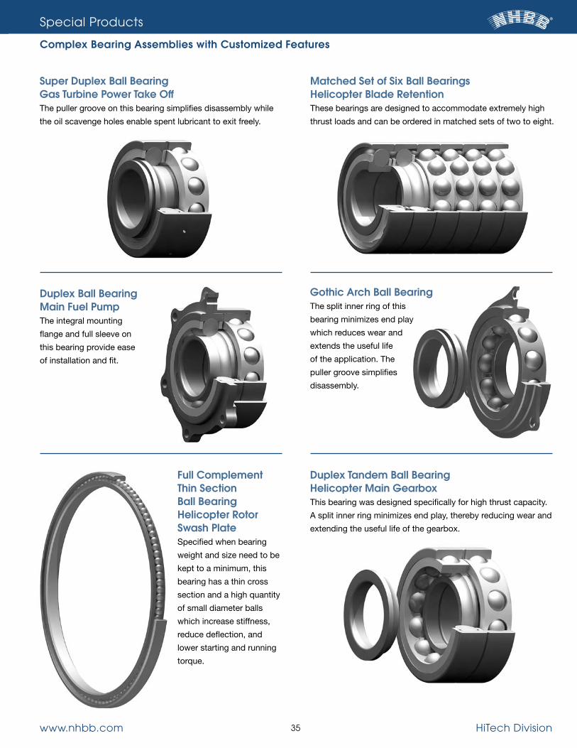
Complex Bearing Assemblies with Customized Features
Duplex Tandem Ball Bearing Helicopter Main GearboxThis bearing was designed specifically for high thrust capacity.
A split inner ring minimizes end play, thereby reducing wear and
extending the useful life of the gearbox.
Gothic Arch Ball BearingThe split inner ring of this
bearing minimizes end play
which reduces wear and
extends the useful life
of the application. The
puller groove simplifies
disassembly.
Duplex Ball Bearing Main Fuel Pump The integral mounting
flange and full sleeve on
this bearing provide ease
of installation and fit.
Matched Set of Six Ball Bearings Helicopter Blade Retention These bearings are designed to accommodate extremely high
thrust loads and can be ordered in matched sets of two to eight.
Super Duplex Ball Bearing Gas Turbine Power Take OffThe puller groove on this bearing simplifies disassembly while
the oil scavenge holes enable spent lubricant to exit freely.
Full Complement Thin Section Ball Bearing Helicopter Rotor Swash PlateSpecified when bearing
weight and size need to be
kept to a minimum, this
bearing has a thin cross
section and a high quantity
of small diameter balls
which increase stiffness,
reduce deflection, and
lower starting and running
torque.

www.nhbb.com 36 HiTech Division

www.nhbb.com 37 HiTech Division
The most common materials used in rolling element bearings
include 52100 chrome steel, 440C stainless steel and M50 tool
steel. While these standard materials are suitable for most
applications, extraordinary operating conditions often require
the use of more advanced alloys such as BG42®, M50 NiL and
Cobalt-based alloys, which offer superb performance at high
speeds, extreme temperatures, heavy loads and in corrosive
conditions. Although cost considerations occasionally override
longevity, the expense involved in more frequent bearing
replacement often justifies the higher initial costs of specifying
longer-lasting specialty metals.
A detailed analysis of the factors involved in a specific applica-
tion is required before selecting the correct material. The
following table, while not a complete list of available alloys, is a
helpful starting point to the selection process. Please contact
NHBB’s Applications Engineering department for help with
making a final determination.
Engineering
Materials
HiTech purchases all products per AMs industry standards and/or nHBB product engineering standards.
●Consumable Electrode vacuum Melted.
■ vacuum Induction Melted/vacuum Arc Remelted.
◆Pressure Electroslag Remelting.
BG42® is a registered trademark of Latrobe specialty steel Company.
Ring Material Properties
MATERIAL SPECIFICATION MELT METHOD FEATURES HARDNESS OPERATING HEAT TREATMENT ATTRIBUTES AND ADvANTAGES AT ROOM TEMP. (HRC) TEMP. LIMIT
AMS 6440 Vacuum degassed Available in tube form 60-64 310 ˚F Good wear and fatigue properties
52100 AMS 6444 CEVM●
Premium quality
58-62 400 ˚F Improved thermal stability
Very low impurity level 60-64 310 ˚F Good wear and fatigue properties
58-62 400 ˚F Improved thermal stability
AMS 5880 Air melt or Corrosion resistance 58-62 325 ˚F Good wear properties vacuum degassed 56-60 825 ˚F Thermal stability with corrosion resistance 440C AMS 5618 CEVM● Premium quality 58-62 325 ˚F Good wear properties Low impurity level 56-60 825 ˚F Thermal stability with corrosion resistance
M50 AMS 6491 VIM/VAR ■ Premium quality 60-64 975 ˚F Excellent fatigue properties High temperature capabilities High thermal stability
BG42® AMS 5749 VIM/VAR ■ Premium quality 61-65 950 ˚F Excellent wear properties Corrosion resistance High thermal stability High temperature capabilities
Nitrogen AMS 5898 P-ESR◆ Extreme corrosion 60-64 850 °F Improved toughness enriched steel resistance Improved compressive strength
Cobalt-based AMS 5759 CEVM● Chemical resistance 50 (min.) 1000 ˚F Good thermal stability alloys High temperature capabilities Low hardness reduction at elevated temperatures
M50 NiL AMS 6278 VIM/VAR ■ Carburized Case: 60 (min.) 975 ˚F High fracture toughness of core High temperature capabilities Accommodates high hoop High cost stresses and cyclic loading

www.nhbb.com 38 HiTech Division
Engineering
Materials
Fatigue LifeBearing steels possess specific characteristics that play a
critical role in bearing performance. Choosing a material with
the correct values for hardness, corrosion resistance, strength,
fracture toughness and fatigue life ensures that a bearing will
function reliably within an application’s operational and environ-
mental parameters. During the material selection process, these
characteristics are weighed against an application’s specific
conditions of temperature, load and corrosiveness.
The most important result of material selection is a bearing’s
longevity. Since different materials possess varying amounts of
fatigue life, each alloy is assigned a life adjustment factor which
is determined through empirical testing. This value provides a
basis for calculating a dependable bearing-life estimate. The life
adjustment factors for various bearing steels are listed on page 45.
Materials ProcessingNHBB maintains exacting metallurgical control of all materials
from the originating mill through all manufacturing processes.
Materials are heat-treated and tempered in-house under con-
trolled atmospheres to bring about the uniform grain structure
and specific hardness appropriate for the intended application.
CarburizingHiTech continually investigates the latest in materials technology,
alloying techniques and heat-treat methods in order to design
and manufacture more complex bearing components for the
aerospace market. One recent development is the capability to
carburize and case harden M50 NiL and other special alloys.
Continual development in gas turbine engine technology is lead-
ing to engines running at greater speeds and temperatures.
These engines require bearings that are capable of enduring
increased demands. When engines run at high speeds and
elevated temperatures, the bearing rings increase in diameter
because of centrifugal forces and thermal expansion.
In order to keep the inner ring fixed to the shaft, a greater press
fit at ambient temperatures is required. However, the tighter
press fit of the inner ring causes high tensile stresses within the
bearing. A typical through-hardened bearing material such as
M50 would crack under these conditions. An excellent solution
to this problem is the use of a carburized steel alloy.
Carburizing is a heat-treat process where alloys with low carbon
content are exposed to a carbon rich atmosphere at an elevated
temperature. Carbon diffuses into the exposed surfaces of the
ring. The ring is then heat-treated to the desired surface hard-
ness while leaving the carbon-deficient core relatively soft.
Finished carburized alloys have a thin outer case, with hardness
values comparable to M50, which provide the needed rolling
contact fatigue properties. In contrast, the inner core of the
carburized ring is relatively soft and ductile, with desirable
fracture toughness properties that allow the bearing to tolerate
high internal tensile stresses. These characteristics create a
tougher bearing that is well suited for tight press fits or highly
loaded flanges.
Materials LaboratoryOur Materials Laboratory is specifically designed and equipped
to perform complex chemical, metallurgical and visual analyses
of the many component parts in ball and roller bearings. Alloy
composition is determined with X-ray diffraction spectrography
and nondestructive test methods. Metallurgical studies are
conducted with a metallograph, which performs microstructure
photography at magnifications from 25 to 2000 times, and
microhardness testers, which investigate surface effects and
alloy homogeneity. The lab also utilizes a scan electron micro-
scope (SEM) to inspect topographies of materials. The SEM has
a magnification range that encompasses that of optical micros-
copy and extends it to the nanoscale.
NHBB’s vacuum carburizing furnace.

www.nhbb.com 39 HiTech Division
Engineering
Internal Bearing Geometry
When establishing the free state internal bearing geometry for
both ball and roller bearings, the specific bearing application
details must be carefully considered. These include the bearing
loads (radial, axial and moment), speeds, operating temperature
range, the specific geometry of the housing and shaft, their fits
and the materials of which they are made.
Proper bearing function is dependent on all of these variables.
The extremes of each variable must be accounted for in the
bearing design to ensure that the maximum and minimum
installed internal bearing geometries result in optimal running
conditions and maximum bearing life. Consult with NHBB’s
Applications Engineering department for assistance with these
special design details.
BALL BEARINGS
For any given bearing load in a ball bearing, internal stresses can
be somewhat controlled by affecting the geometric relationship
between the balls and raceways. When running under a load,
force is transmitted from one bearing ring to the other through
the ball set. Since the contact area between each ball and the
rings is relatively small, even moderate loads can produce
stresses of tens or even hundreds of thousands of pounds per
square inch. Because internal stress levels have such an impor-
tant effect on bearing life and performance, internal geometry
must be carefully chosen for each application in order for bear-
ing loads to be distributed properly.
Raceway, Track Diameter and Track RadiusThe raceway in a ball bearing is the circular groove formed in
the outside surface of the inner ring and in the inside surface of
the outer ring. When the rings are aligned, these grooves form a
circular track that contains the ball set.
The track diameter and track radius are two dimensions that
define the configuration of each raceway. Track diameter is the
measurement of the diameter of the imaginary circle running
around the deepest portion of the raceway, whether it is an
inner or outer ring. This measurement is made along a line
perpendicular to, and intersecting with, the axis of rotation.
Track radius describes the cross section of the arc formed by
the raceway groove. It is measured when viewed in a direction
perpendicular to the axis of rotation. In the context of ball
bearing terminology, track radius has no mathematical relation-
ship to track diameter. The distinction between the two is
shown here.
Radial and Axial PlayMost ball bearings are assembled in such a way that a slight
amount of looseness exists between balls and raceways. This
looseness is referred to as radial play and axial play. Radial play
is the maximum distance that one bearing ring can be dis-
placed with respect to the other in a direction perpendicular to
the bearing axis when the bearing is in an unmounted state.
Axial play, or end play, is the maximum relative displacement
between the two rings of an unmounted ball bearing in the
direction parallel to the bearing axis (shown here).
Since radial play and axial play are both consequences of the
same degree of looseness between the components in a ball
bearing, they bear a mutual dependence. While this is true, both
values are usually quite different in magnitude. Radial play can
often vary between .0002" and .002", while axial play may
range anywhere from .001" to .020".
In most ball bearing applications, radial play is functionally more
critical than axial play. While radial play has become the stan-
dard purchasing specification, users may also specify axial play
requirements. It must be kept in mind, however, that the values
of radial play and axial play for any given bearing design are
mathematically interdependent.
TrackRadius
Track Diameter
AxialPlay
GageLoad
GageLoad
GageLoad
GageLoad
GageLoad
GageLoad
Radial Play
Radial Play Axial Play

www.nhbb.com 40 HiTech Division
Engineering
Internal Bearing Geometry
These general statements can be made about ball bearing
radial play:
1. The initial contact angle of the bearing is directly related to
radial play—the higher the radial play, the higher the contact
angle.
2. For support of pure radial loads, a low contact angle is
desirable.
3. Where thrust loading is predominant, a higher contact
angle (or radial play) is necessary.
4. Radial play is affected by any interference fit between
the shaft and bearing I.D. or between the housing and
bearing O.D.
Track CurvatureTrack curvature is an expression that defines the difference
between the arc of the raceway’s track radius and the arc
formed by the profile of the slightly smaller ball that runs in that
raceway. It is simply the track radius of a bearing raceway
expressed as a percentage of ball diameter. This number is a
convenient index of “fit” between the raceway and ball, and is
always slightly greater than the corresponding arc of the ball.
Track curvature values typically range from approximately 52%
to 58%. The lower percentage, tight fitting curvatures are useful
in applications where heavy loads are encountered while the
higher percentage, loose curvatures are more suitable for
torque-sensitive applications. Curvatures less than 52% are
generally avoided because of excessive rolling friction that is
caused by the tight conformity between the ball and raceway.
Values above 58% are also avoided because of the high stress
levels that can result from the small ball-to-raceway conformity
at the contact area.
Contact AngleThe contact angle is the angle between a plane perpendicular
to the ball bearing axis and a line joining the two points where
the ball makes contact with the inner and outer raceways. The
contact angle of a ball bearing is determined by its free radial
play value, as well as its inner and outer track curvatures.
The contact angle of thrust-loaded bearings provides an indica-
tion of ball position inside the raceways. When a thrust load is
applied to a ball bearing, the balls will move away from the
median planes of the raceways and assume positions some-
where between the deepest portions of the raceways and their
edges. The following drawing illustrates the concept of contact
angle by showing a cross sectional view of a ball bearing that is
loaded in pure thrust.
Free Angle of MisalignmentAs a result of axial and radial play, which is purposely permitted
to exist between the components of most ball bearings, the inner
ring can be tilted a small amount in relation to the outer ring. This
displacement is called free angle of misalignment. The amount
of misalignment allowable in a given ball bearing is determined
by its radial play and track curvature values. The misalignment
capability of a bearing can have positive practical significance
because it enables a ball bearing to accommodate small dimen-
sional variations that may exist in associated shafts and housings.
The performance of a misaligned bearing will be degraded to a
certain extent, but for slight misalignments under reasonably
light loads the effects will not be significant in most cases.
This concept is shown below. In general, the misalignment a
bearing is subjected to due to the shaft and housing’s physical
arrangement should never exceed the bearing’s free angle
of misalignment.
Track Radius
Ball Diameter
LoadedContact Angle
Thrust
Thrust
0f~

www.nhbb.com 41 HiTech Division
Engineering
Internal Bearing Geometry
ROLLER BEARINGS
Radial Play Radial play in a roller bearing is similar to that of a ball bearing,
where they are assembled in such a way that a slight amount of
looseness exists between rollers and raceways. As with ball
bearings, radial play is the maximum distance that one bearing
ring can be displaced with respect to the other in a direction
perpendicular to the bearing axis when the bearing is in an
unmounted state (shown here).
Some general statements can be made about roller bearing
radial play:
1. Roller bearings are used for support of predominantly radial
loads. Minimal thrust loading is tolerable, with a general guide-
line being 10% of the radial load.
2. Ideally, a roller bearing will perform best with a minimum
installed radial play. This ensures that the load is distributed
among the maximum number of roller elements, thereby mini-
mizing the stresses.
3. Radial play is affected by any interference fit between the shaft
and bearing I.D. or between the housing and bearing O.D.
Roller End PlayWith roller bearings, roller end play (a.k.a. axial play or roller to
guide flange clearance) is completely independent of radial play.
Roller end play is the maximum relative displacement of the
roller element within the confines of the double guide flanged
(u-shaped) ring. Close attention and control of end play is
required to manage roller skewing and to provide for optimum
tracking at all loads and speeds.
Free Angle of MisalignmentAs with ball bearings, roller bearings have some capacity for
misalignment. As a result of the previously described looseness,
or play, which is purposely permitted to exist between the bear-
ing components, the inner ring can be tilted a small amount in
relation to the outer ring. This displacement is called free angle
of misalignment. The amount of misalignment allowable in a giv-
en roller bearing is determined by its radial play, end play, guide
flange angle and roller element geometry, namely the roller flat
length and crown radius values (turn to page 43 for more infor-
mation). Again, the misalignment capability of a roller bearing
can also have positive practical significance because it enables
the bearing to accommodate small dimensional variations that
may exist in associated shafts and housings. The performance
of a misaligned roller bearing will be degraded to a certain
extent, but for slight misalignments under reasonably light loads,
the effects will not be significant in most cases. In general, the
misalignment a bearing is subjected to should never exceed
the bearing’s free angle of misalignment.
GageLoad
GageLoad
Radial Play
End Play
0f~

www.nhbb.com 42 HiTech Division
Engineering
Internal Bearing Geometry
Calculating Radial Play, Axial Play and Contact Angle
Radial Play
PD = 2B d (1 – cos b0)
PD = 2B d – (2Bd)2 – PE
2
Axial Play
PE = 2B d sin b0
PE = 4B dPD – PD2
Contact Angle
b0 = cos –1 2B d – PD
2Bd
b0 = sin –1 PE
2Bd
PD = Radial play
PE = Axial play
b0 = Contact angle
B = Total curvature = ( fi + fo – 1)
f i = Inner ring curvature*
fo = Outer ring curvature*
d = Ball diameter
* Expressed as the ratio of race radius to ball diameter.
Analyzing an Application’s Impact on Installed Radial PlayOnce a preliminary value for radial play has been specified, it is
important to analyze how mounting and operating conditions will
affect the internal clearance within the bearing. The factors to
consider include interference fits, material properties, tempera-
ture differentials, and high rotational speeds.
• Interference Fits: Press fits reduce radial play by causing
either the inner or outer ring to deflect when the bearing is
installed. While the force generated by the interference fit is
absorbed by both components (i.e., shaft and inner ring), the
amount of deflection depends on the amount of interference,
the properties of the materials and the configuration of the
shaft or housing. For example, a solid shaft made of a stiff
material will deflect the inner ring more than a hollow shaft
made of a flexible material.
• Mating Materials: A bearing’s installed internal clearance is
affected when mating components are made from materials
that expand at different rates when subject to the same
temperatures. When the rates of expansion are drastically
different—e.g., the housing expands at twice the rate of the
bearing’s outer ring—the extremes of the operating tempera-
ture range could result in an unacceptable press fit and
subsequent loss of radial play.
• Nonuniform Operating Temperatures: Occasionally, a bear-
ing’s inner and outer rings experience different operating
temperatures. When this happens, the rings will expand by dif-
ferent amounts, thus altering the bearing’s internal clearance.
• Centrifugal Force: High operating speeds generate centrifu-
gal forces that can cause a bearing’s rotating ring to expand.
The result could affect internal clearance.
Prior to finalizing the design, it is necessary to determine the
extent to which the above factors will impact the bearing’s inter-
nal geometry and adjust the specified radial play accordingly.
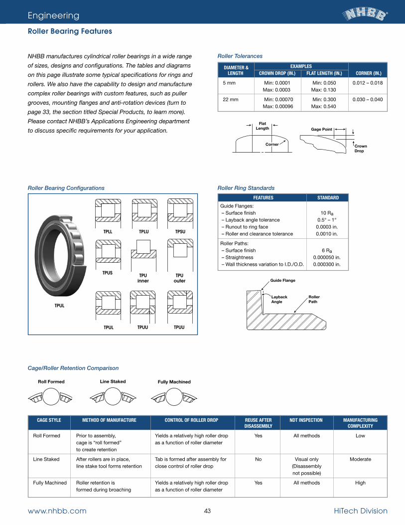
www.nhbb.com 43 HiTech Division
NHBB manufactures cylindrical roller bearings in a wide range
of sizes, designs and configurations. The tables and diagrams
on this page illustrate some typical specifications for rings and
rollers. We also have the capability to design and manufacture
complex roller bearings with custom features, such as puller
grooves, mounting flanges and anti-rotation devices (turn to
page 33, the section titled Special Products, to learn more).
Please contact NHBB’s Applications Engineering department
to discuss specific requirements for your application.
Engineering
Roller Bearing Features
Guide Flange
RollerPath
LaybackAngle
Roller Bearing Configurations Roller Ring Standards
Roller Tolerances
Cage/Roller Retention Comparison
Fully MachinedLine Staked
FlatLength
Corner
Gage Point
CrownDrop
FEATURES STANDARD
Guide Flanges: – Surface finish 10 Ra – Layback angle tolerance 0.5° – 1° – Runout to ring face 0.0003 in. – Roller end clearance tolerance 0.0010 in.
Roller Paths: – Surface finish 6 Ra – Straightness 0.000050 in. – Wall thickness variation to I.D./O.D. 0.000300 in.
DIAMETER & EXAMPLES LENGTH CROWN DROP (IN.) FLAT LENGTH (IN.) CORNER (IN.)
5 mm Min: 0.0001 Min: 0.050 0.012 – 0.018 Max: 0.0003 Max: 0.130
22 mm Min: 0.00070 Min: 0.300 0.030 – 0.040 Max: 0.00096 Max: 0.540
CAGE STYLE METHOD OF MANUFACTURE CONTROL OF ROLLER DROP REUSE AFTER NDT INSPECTION MANUFACTURING DISASSEMBLY COMPLEXITY
Roll Formed Prior to assembly, Yields a relatively high roller drop Yes All methods Low cage is “roll formed” as a function of roller diameter to create retention
Line Staked After rollers are in place, Tab is formed after assembly for No Visual only Moderate line stake tool forms retention close control of roller drop (Disassembly not possible)
Fully Machined Roller retention is Yields a relatively high roller drop Yes All methods High formed during broaching as a function of roller diameter
Roll Formed
TPLL
TPUL
TPU inner
TPLU
TPU outer
TPSU
TPUU
TPUU
TPUS
TPUL

www.nhbb.com 44 HiTech Division
Engineering
Load Ratings and Bearing Life
The load ratings in this catalog are based on ANSI/ABMA
Standards 9 and 11. These standards specify the accepted
methods for calculating load ratings and fatigue life of ball and
cylindrical roller bearings. Since a multitude of variables may
affect these calculations, they should be used for baseline
estimates only. Load ratings for your application’s specific
operating conditions should be calculated before making a
final bearing choice.
Basic Dynamic Load RatingThe Basic Load Rating (C) for a radial or angular contact ball
bearing is a calculated constant radial load which a bearing with
a stationary outer ring can theoretically endure for a rating life of
1,000,000 revolutions of the inner ring. The ratings shown in this
catalog are defined by ANSI/ABMA Standard 9 and Standard 11.
The ratings for noncatalog bearings may be determined by
referring to this standard.
Static Load RatingA static load is a load acting on a nonrotating bearing. Experi-
ence shows that a total permanent deformation of 0.0001 of the
rolling element diameter, at the center of the most heavily loaded
rolling element/raceway contact, can be tolerated in most bear-
ing applications without the bearing operation being impaired.
The basic static load rating is, therefore, that load which pro-
duces the above deformation. As with the dynamic load ratings,
the static rating determinations can be found in ANSI/ABMA
Standard 9 and Standard 11.
Rating Life Bearing fatigue life is a baseline estimate of the number of revo-
lutions or hours that a bearing will operate before failing. The
principal factor at play is metal fatigue, so failure is defined by
the presence of spalling or flaking on a bearing’s raceways.
Since, in reality, identical bearings operating under identical
conditions fail at unpredictable intervals, and since there is no
way to predict the actual life of a specific bearing, the industry
utilizes a statistical formula to calculate rating life. The calcula-
tions shown in the next column involve many parameters and are
based on historical test data.
Reliability—L10The standard value L10 equals the total number of revolutions
that 90% of a group of identical bearings will theoretically meet
or exceed. For a single bearing, L10 also refers to the life associ-
ated with 90% reliability. The life which 50% of the group of
bearings will meet or exceed (median life, or L50) is usually no
greater than five times the rating life (refer to the table under Life
Adjustment Factors on page 45).
Basic Equations
Ball Bearings
L (cycles) = (C/Pr)3 x a1 x a2
Roller Bearings
L (cycles) = (C/Pr)10/3 x a1 x a2
Convert to Hours of Operation
L (hours) = 1,000,000/N x 60
L (cycles) = Cycles (x 1 million)
C = Dynamic load rating
Pr = Equivalent radial load
a1 = Reliability adjustment factor
a2 = Material adjustment factor
N = rpm
Calculating Equivalent Radial LoadMore often than not, bearings with primarily radial loads are
subject to some axial forces. When the magnitude of the axial
component of the load is greater than a negligible value, it is
helpful to translate the combined radial and axial load into a
radial load so that the basic life equation may be used. This
radial load, known as the equivalent radial load, is defined as
that constant stationary radial load which, if applied to a rotating
inner ring, would give the same life as that which the bearing will
attain under the actual conditions of load and rotation. For con-
ventional bearing types other than those with filling notches, the
equivalent radial loads are given by the maximum of the two
values where:
a) Pr = VFr
b) Pr = XVFr + YFa
V is a rotation factor
X is a radial factor
Y is a thrust factor
Fr is the radial load
Fa is the axial load
Consult the table on page 45 for determining values X, Y and e.
In all series, the rotational factor V is 1.0 for inner ring rotation
and 1.2 for outer ring rotation with respect to load. The factor e
(last column) represents the ratio of Fa/VFr for which the two
equations are equal. If the ratio of loads is such that Fa/VFr e,
then formula (a) is used; if Fa/VFr > e, then formula (b) is used.

www.nhbb.com 45 HiTech Division
Life Adjustment FactorsWhen a more conservative approach than conventional rating
life (L10) is desired, the ABMA offers a means for such estimates.
The table below provides selected multipliers for calculating
failure rates down to 1% (L1).
Material FactorsCertain materials are proven to have greater fatigue life than
others operating under identical conditions. The theoretical L10
dynamic life is based on air-melt steel and standard ABMA
formulas. The life adjustment factors for materials frequently
used are shown here:
Other Life Adjustment FactorsThe conventional rating life often has to be modified as a conse-
quence of application abnormalities. The following conditions all
have the practical effect of modifying the ideal theoretical rating
life of L10:
a) Vibration and/or shock-impact loads
b) Angular misalignment
c) High speed
d) Operating at elevated temperatures
e) Lubricant effects
NHBB can provide reliable bearing life estimates based on semi-
empirical data to assist in accurately forecasting bearing life.
Engineering
Load Ratings and Bearing Life
RELIABILITY RATING LIFE LIFE ADJUSTMENT FACTOR
90 L10 1.00
95 L5 0.62
96 L4 0.53
97 L3 0.44
98 L2 0.33
99 L1 0.21
MATERIAL FACTOR
M50 NiL 20
M50 10
52100 VIM/VAR 7
52100 CEVM 5
BG42® 3
52100 1
440C 0.8
Radial 25 2.30 0.19 deep groove 50 1.99 0.22 ball bearings 100 1.71 0.26 150 1.55 0.28 200 1 1.2 0.056 1.45 0.30 300 1.31 0.34 500 1.15 0.38 750 1.04 0.42 1,000 1.00 0.44
Angular 25 2.30 0.23 contact 50 1.99 0.26 ball bearings 100 1.71 0.30 with contact 150 1.55 0.34 angle: 200 1 1.2 0.56 1.45 0.36 300 1.31 0.40 5° 500 1.15 0.45 750 1.04 0.50 1,000 1.00 0.52
25 1.88 0.29 50 1.71 0.32 100 1.52 0.36 150 1.41 0.38 10° 200 1 1.2 0.46 1.34 0.40 300 1.23 0.44 500 1.10 0.49 750 1.01 0.54 1,000 1.00 0.54
25 1.47 0.38 50 1.40 0.40 100 1.30 0.43 150 1.23 0.46 15° 200 1 1.2 0.44 1.19 0.47 300 1.12 0.50 500 1.02 0.55 750 1.00 0.56 1,000 1.00 0.56
20° 1 1.2 0.43 1.00 0.57 25° 1 1.2 0.41 0.87 0.68 30° 1 1.2 0.39 0.76 0.80 35° 1 1.2 0.37 0.66 0.95 40° 1 1.2 0.35 0.57 1.14
IN RELATION TO THE LOAD SINGLE ROW BEARINGS BEARING THE INNER RING IS: TYPE UNITS ROTATING STATIONARY LBS, IN. v v X Y e
Factors X, V and Y
FaZD2 Fa > e
vFr
Additional nomenclature is as follows:– Z is the number of balls– D is the ball diameter in inches
values of X, Y and e for load or contact angle other than shown are obtained by linear interpolation.
BG42® is a registered trademark of Latrobe specialty steel Company.

www.nhbb.com 46 HiTech Division
Engineering
Preload and Duplex Bearings
The initial axial load placed on a set of bearings during
installation is defined as preload. Preloading facilitates precise
control over the operating geometry of the bearing’s mating
parts, a useful function in applications where axial and radial
movement must be held within critical limits. The specific
functional attributes include:
• Removal of the free axial and radial play for precise shaft
positioning. With the removal of free play, the geometries
of the bearings dictate the radial and axial run-outs;
• Establishment of a precise amount of axial and radial stiffness.
The spring rates in the axial and radial directions are constant
as long as the preload is maintained;
• Minimization of ball skidding. Properly designed preloading
keeps the balls under load in high speed or rapid acceleration/
deceleration operation;
• Allowance of load sharing between bearings. Increased axial
capacities can be realized using tandem duplexes.
Methods:Bearings may be preloaded using one of the following
approaches:
1. Specify factory “built-in” preload sets. Since each set is
checked for preload level as it is built, these duplex bearings
provide the greatest control over preload. The clamping load
can be applied either with a single nut tightened to a specific
torque, or a clamping ring with multiple screws tightened to a
prescribed torque.
2. Use shims and/or spacers to provide the preload deflection
offsets. The appropriate faces can then be clamped as above
to provide the preload. This method can result in wide ranges
of preload, as lengths vary with shims or spacers.
3. Use compression springs (wave washers, Belleville washers,
etc.) to apply the initial axial load to the set. Due to toler-
ance stack-ups, this method is not very precise. The spring’s
placement (with its lower spring rate) is critical for preventing
preload unloading due to external axial loads.

www.nhbb.com 47 HiTech Division
Engineering
Preload and Duplex Bearings
Duplex Bearing Configurations
DB (back to back): The outboard faces of this set’s inner rings
are loaded, creating opposing contact angles that diverge to
the bearing axis. Factory “built-in” offsets in the unloaded state
provide the proper preload deflection when the inner races are
clamped together. This configuration has higher moment stiff-
ness than the DF configuration (under the same preload, DB
and DF have identical radial and axial stiffness rates). Use DB
when the shaft temperature is higher than the housing tempera-
ture, as this configuration minimizes preload build-up due to dif-
ferential expansions, and reduces heat buildup in the bearings.
DF (face to face): The outboard faces of this set’s outer rings
are loaded, creating opposing contact angles that converge to
the bearing axis inside the bearing envelope. Factory “built-in”
offsets in the unloaded state provide the proper preload when
the outer races are clamped together. This configuration has
lower moment stiffness than DB, which allows for some
misalignment. Use DF when the housing temperature is higher
than the shaft temperature.
DT (tandem): The contact angles of the bearings are oriented
in the same direction, allowing for increased load sharing
in the axial direction. DT has the same radial stiffness (with
equal preload) as the DB or DF configurations, but its axial
stiffness is twice that of either pair with the same preload.
Factory “built-in” offsets in the unloaded state provide the
proper preload when the outer race on one side and the inner
race on the opposite side are loaded. To achieve a preloaded
condition, DT requires an opposing bearing or bearing-set.
DU (universal): The faces are flush on both sides with the
factory “built-in” preload, so this configuration can be oriented
in any configuration: DB, DF or DT.
PreloadOffset
LoadInner
LoadInner
Bearings in True State Bearings Preloaded O.D. Marking
PreloadOffset
Bearings in True State Bearings Preloaded O.D. Marking
LoadOuter
LoadOuter
PreloadOffset (TYP)
Bearings in True State Bearings Preloaded O.D. Marking
LoadOuter
LoadInner
LoadInner
LoadOuter
Bearing Preloaded O.D. Marking

www.nhbb.com 48 HiTech Division
Engineering
Shaft and Housing Fits
Determining Load ClassificationTo determine whether a load is either light, normal, or heavy,
divide an application’s equivalent radial load (Pr) by the bearing’s
dynamic radial load rating (Cr). Compare the results with Table I.
See page 44 for a definition and method for calculating equiva-
lent radial load.
Establishing accurate shaft and housing fits is critical to
achieving the best possible bearing performance. Fits that are
too loose or too tight can create conditions that lead to prema-
ture bearing failure. Under certain conditions, overly loose fits
can lead to corrosion of the shaft or bore, excessive wear, poor
bearing rotation, and excessive vibration and noise. Exceedingly
tight fits often cause large mounting and dismounting forces,
unwanted preload, overheating, and a reduction in radial play.
Shaft and housing fits are governed by the assembly’s specific
operating requirements and conditions. The various factors to
consider include the type and amount of load, operating
temperature, running accuracy requirements, material composi-
tion and machining tolerances of mating components, and the
size and type of bearing specified.
Generally speaking, the rotating ring of the bearing requires an
interference fit with either the shaft or housing, and the nonrotat-
ing ring demands a slight loose fit with its mating component.
Thin cross section bearings, such as NHBB’s thin section and
torque tube series, are inherently more sensitive to shaft and
housing fits than metric ball and roller bearings. In most
conditions a line-to-line-to-loose fit is more appropriate for thin
cross sections. Heavier cross section bearings require tighter
fits than light cross section bearings. In either case, extreme
interference fits should only be used in conjunction with larger
internal clearance in order to accommodate the subsequent
loss of radial play.
The specific recommendations for shaft and housing fits for
metric series radial ball and roller bearings are covered under
ABMA Standard 7. The standards do not apply to inch series
bearings, so consult NHBB’s Applications Engineering depart-
ment for assistance.
The following tables provide fit recommendations for a variety
of operating conditions and load magnitudes. Table I specifies
the load classification. Tables II and III specify standard shaft
and housing tolerance classifications. Tables IV and V on pages
50 and 51 identify the specific fit tolerances for NHBB’s metric
series ball and cylindrical roller bearings up to 12” O.D. For help
with verifying the correct fit for your application, or to request a
complete bearing optimization, please consult NHBB’s Applica-
tions Engineering department.
Table I: Load Classification
LIGHT NORMAL HEAvY
Ball Bearings 0.0 – 0.06 0.06 – 0.12 0.12 – 0.40
Cylindrical 0.0 – 0.07 0.07 – 0.18 0.14 – 0.40 Roller Bearings
Tight Fit Range
Tight Fit Range
ShaftO.D.ToleranceRange Nominal Bearing Bore
Bore Tolerance
Loose Fit Range
Loose Fit Range
g6
h6h5
j5j6
k5k6
m5m6
n6
p6
r6 r7
HousingBoreToleranceRange
Nominal Bearing O.D.
O.D. Tolerance
H8G7
F7
H7H6
J7J6
K6 K7
M6 M7
N7
P6 P7
N6
Diagram of Fit Tolerances*
* Copyright American Bearing Manufacturers Association, Inc. All rights reserved. Used with permission.

www.nhbb.com 49 HiTech Division
Engineering
Shaft and Housing Fits
Table II: Classification for Shaft Tolerances*
Table III: Classification for Housing Tolerances*
DESIGN & OPERATING CONDITIONS BALL BEARINGS CYLINDRICAL ROLLER BEARINGS
ROTATIONAL INNER RING AXIAL RADIAL LOADING d TOLERANCE d TOLERANCE
CONDITIONS DISPLACEABILITY OvER INCL. CLASSIFICATION ● OvER INCL. CLASSIFICATION●
0 1.57 j6 ■ 0 0.71 h5 1.57 5.51 k6 ■ Light 0.71 All j6 ■ 5.51 12.60 m6 ■ 12.60 19.70 n6 19.70 All p6
0 1.57 k5 1.57 3.94 m5 Normal 0 0.71 j5 3.94 5.51 m6 0.71 All k5 5.51 12.60 n6 12.60 19.70 p6 19.70 — — All r6
0 1.57 m5 1.57 2.56 m6 Heavy 0.71 3.94 k5 2.56 5.51 n6 3.94 All m5 5.51 7.87 p6 7.87 19.70 r6 19.70 ———---All r7
Inner ring must Light, be easily axially normal All sizes g6 All sizes g6 displaceable or heavy
Inner ring need Light, not be easily axially normal All sizes h6 All sizes h6 displaceable or heavy
DESIGN AND OPERATING CONDITIONS TOLERANCE ROTATIONAL CONDITIONS LOADING OTHER CONDITIONS OUTER RING AXIAL DISPLACEABILITY CLASSIFICATION ●
Heat input through shaft G7 ▲
Outer ring stationary
Light, normal or heavy Housing split axially Outer ring easily axially displaceable H7 ■
in relation to load direction H6 ■
Shock with temporary Housing not split axially
complete unloading J6 ■
Light
Load direction indeterminate Normal or heavy Transitional range ◆ K6 ■
Heavy shock Split not recommended
M6 ■
Light
Outer ring rotating in relation Normal or heavy Outer ring not easily axially displaced
N6 ■
to load direction
Heavy Thin wall housing not split P6 ■
Dimensions are in inches.
For metric radial ball and roller bearings of tolerance classes ABEC 1 and RBEC 1.
● values relate to solid steel shafts only. Tighter fits may be needed for hollow or nonferrous shafts.
■ select higher classification for greater accuracy (e.g., j5 for j6).
For metric radial ball and roller bearings of tolerance classes ABEC 1 and RBEC 1.
● values relate to cast iron steel housings. Tighter fits may be needed for nonferrous alloys.
■substitute lower classifications where wider tolerances are allowed. Please consult the factory.
▲ Use F7 if temperature differential between inner and outer ring of a large bearing is greater than 10 ˚C.
◆ The outer ring may either be tight or loose in the housing.
Inner ring rotating in relation to load or load direction is indeterminate
Inner ring stationary in relation to
load direction
* Copyright American Bearing Manufacturers Association, Inc. All rights reserved. Used with permission.

www.nhbb.com 50 HiTech Division
Engineering
Shaft and Housing Fits
0.1181 0.2362 0 -2 5L 0 3L 0 2L +1 1L +2 1L +2 0 0.1181 0.2362 0 +4 2T -3 -5 1T -3 3T -2 3T -1 4T -1 5T 0 5T -3 +2 7T
0.2362 0.3937 0 -2 6L 0 4L 0 2L +2 1L +3 1L +3 0 0.2362 0.3937 0 +5 2T -3 -6 1T -4 3T -2 3T -1 5T -1 6T 0 6T -3 +2 8T
0.3937 0.7087 0 -2 7L 0 4L 0 3L +2 1L +3 1L +4 0 0.3937 0.7087 0 +6 3T -3 -7 1T -4 3T -3 3T -1 5T -1 6T 0 7T -3 +3 9T
0.7087 1.1811 0 -3 8L 0 5L +2 2L +4 2L +4 1T 0.7087 1.1811 0 +7 3T -4 -8 1T -5 4T -2 6T -2 8T +1 8T -4 +3 11T
1.1811 1.9685 0 -4 10L 0 6L +2 2L +4 2L +5 1T +7 1T 1.1811 1.9685 0 +8 4T +10 4T -4.5 -10 0.5T -6 4.5T -2 6.5T -2 8.5T +1 9.5T +1 11.5T -4.5 +4 12.5T +4 14.5T
1.9685 3.1496 0 -4 11L 0 7L +2 3L +5 3L +6 1T +8 1T 1.9685 3.1496 0 +9 4T +12 4T +15 8T -6 -11 2T -7 6T -3 8T -3 11T +1 12T +1 14T -6 +4 15T +4 18T +8 21T
3.1496 4.7244 0 -5 13L 0 9L +2 4L +5 4L +7 1T +10 1T 3.1496 4.7244 0 +11 5T +14 5T +18 9T +23 15T -8 -13 3T -9 8T -4 10T -4 13T +1 15T +1 18T -8 +5 19T +5 22T +9 26T +15 31T
4.7244 7.0866 0 -6 15L 0 10L +3 4L +6 4L +8 1T +11 1T 4.7244 7.0866 0 +13 6T +16 6T +20 11T +27 17T +35 26T -10 -15 4T -10 10T -4 13T -4 16T +1 18T +1 21T -10 +6 23T +6 26T +11 30T +17 37T +26 45T
7.0866 7.8740 0 -6 17L 0 11L +3 5L +6 5L +9 2T 7.0866 7.8740 0 +15 7T +18 7T +24 12T +31 20T +42 30T -12 -17 6T -11 12T -5 15T -5 18T +2 21T -12 +7 27T +7 30T +12 36T +20 43T +30 54T
7.8740 8.8583 0 -6 17L 0 11L +3 5L +6 5L +9 2T 7.8740 8.8583 0 +15 7T +18 7T +24 12T +31 20T +43 31T +50 31T -12 -17 6T -11 12T -5 15T -5 18T +2 21T -12 +7 27T +7 30T +12 36T +20 43T +31 55T +31 62T
8.8583 9.8425 0 -6 17L 0 11L +3 5L +6 5L +9 2T 8.8583 9.8425 0 +15 7T +18 7T +24 12T +31 20T +44 33T +51 33T -12 -17 6T -11 12T -5 15T -5 18T +2 21T -12 +7 27T +7 30T +12 36T +20 43T +33 56T +33 63T
9.8425 11.0236 0 -7 19L 0 13L +3 6L +6 6L +11 2T 9.8425 11.0236 0 +17 8T +20 8T +26 13T +35 22T +50 37T +57 37T -14 -19 7T -13 14T -6 17T -6 20T +2 25T -14 +8 31T +8 34T +13 40T +22 49T +37 64T +37 71T
d TOLERANCE CLASSIFICATIONS d TOLERANCE CLASSIFICATIONS g6 h6 h5 j5 j6 k5 k6 m5 m6 n6 p6 r6 r7
OvER INCLUDING TOLERANCE
SHAFT FIT SHAFT FIT SHAFT FIT SHAFT FIT SHAFT FIT SHAFT FIT SHAFT FIT OvER INCLUDING TOLERANCE
SHAFT FIT SHAFT FIT SHAFT FIT SHAFT FIT SHAFT FIT SHAFT FIT
0.3937 0.7087 +0 +6 16L +2 12L 0 14L 0 10L 0 7L -2 5L -3 7L -4 4L 0.3937 0.7087 +0 -5 5L -6 1L -7 3L -8 1T -9 1L -10 3T -11 1T -3 +13 6L +9 2L +11 0 +7 0 +4 0 +2 2T +4 3T +1 4T -3 +2 5T -2 6T 0 7T -4 8T -2 9T -6 10T -4 11T
0.7087 1.1811 +0 +8 19.5L +3 14.5L 0 16.5L 0 11.5L 0 8.5L -2 6.5L -4 8.5L -4 4.5L 0.7087 1.1811 +0 -6 5.5L -7 1.5L -8 3.5L -9 0.5T -11 0.5L -12 3.5T -14 2.5T -3.5 +16 8L +11 3L +13 0 +8 0 +5 0 +3 2T +5 4T +1 4T -3.5 +2 6T -2 7T 0 8T -4 9T -3 11T -7 12T -6 14T
1.1811 1.9685 +0 +10 24.5L +4 17.5L 0 19.5L 0 14.5L 0 10.5L -2 8.5L -4 10.5L -5 5.5L 1.1811 1.9685 +0 -7 7.5L -8 2.5L -10 4.5L -11 0.5T -13 1.5L -15 3.5T -17 2.5T -4.5 +20 10L +13 4L +15 0 +10 0 +6 0 +4 2T +6 4T +1 5T -4.5 +3 7T -2 8T 0 10T -5 11T -3 13T -8 15T -7 17T
1.9685 3.1496 +0 +12 29L +4 21L 0 23L 0 17L 0 12L -2 10L -5 12L -6 7L 1.9685 3.1496 +0 -8 9L -9 3L -12 5L -13 1T -15 1L -18 5T -20 3T -5 +24 12L +16 4L +18 0 +12 0 +7 0 +5 2T +7 5T +2 6T -5 +4 8T -2 9T 0 12T -6 13T -4 15T -10 18T -8 20T
3.1496 4.7244 +0 +14 34L +5 25L 0 27L 0 20L 0 15L -2 12L -5 15L -7 8L 3.1496 4.7244 +0 -10 10L -11 4L -14 6L -15 0 -18 2L -20 6T -23 3T -6 +18 14L +19 5L +21 0 +14 0 +9 0 +6 2T +9 5T +2 7T -6 +4 10T -2 11T 0 14T -6 15T -4 18T -12 20T -9 23T
4.7244 5.9055 +0 +17 40L +6 28L 0 32L 0 23L 0 17L -3 14L -6 17L -8 9L 4.7244 5.9055 +0 -11 12L -13 4L -16 7L -18 1T -20 2L -24 7T -27 4T -7 +33 17L +21 6L +25 0 +16 0 +10 0 +7 3T +10 6T +2 8T -7 +5 11T -3 13T 0 16T -8 18T -5 20T -14 24T -11 27T
5.9055 7.0866 +0 +17 43L +6 31L 0 35L 0 26L 0 20L -3 17L -6 20L -8 12L 5.9055 7.0866 +0 -11 15L -13 7L -16 10L -18 2L -20 5L -24 4T -27 1T -10 +33 17L +21 6L +25 0 +16 0 +10 0 +7 3T +10 6T +2 8T -10 +5 11T -3 13T 0 16T -8 18T -5 20T -14 24T -11 27T
7.0866 9.8425 +0 +20 50L +6 36L 0 40L 0 30L 0 23L -3 21L -6 24L -9 14L 7.0866 9.8425 +0 -13 17L -15 9L -18 12L -20 3L -24 6L -28 4T -31 1T -12 +38 20L +24 6L +28 0 +18 0 +11 0 +9 3T +12 6T +2 9T -12 +5 13T -3 15T 0 18T -9 20T -6 24T -16 28T -13 31T
9.8425 12.4016 +0 +22 57L +7 41L 0 46L 0 34L 0 27L -3 24L -6 28L -11 16L 9.8425 12.4016 +0 -14 20L -16 10L -20 14L -22 4L -26 8L -31 5T -35 0 -14 +43 22L +27 7L +32 0 +20 0 +13 0 +10 3T +14 6T +2 11T -14 +6 14T -4 16T 0 20T -10 22T -6 26T -19 31T -14 35T
d TOLERANCE CLASSIFICATIONS d TOLERANCE CLASSIFICATIONS F7 G7 H8 H7 H6 J6 J7 k6 k7 M6 M7 N6 N7 P6 P7
OvER INCLUDING TOLERANCE HOUSING FIT HOUSING FIT HOUSING FIT HOUSING FIT HOUSING FIT HOUSING FIT HOUSING FIT HOUSING FIT
OvER INCLUDING TOLERANCE HOUSING FIT HOUSING FIT HOUSING FIT HOUSING FIT HOUSING FIT HOUSING FIT HOUSING FIT FIT
Table IV: Bore Fit Tolerances*
Table V: Housing Fit Tolerances*
Dimensions are in inches.
shaft deviations and resultant fits are in 0.0001 inches.
Dimensions are in inches.
Housing deviations and resultant fits are in 0.0001 inches.* Copyright American Bearing Manufacturers Association, Inc.
All rights reserved. Used with permission.

www.nhbb.com 51 HiTech Division
Engineering
Shaft and Housing Fits
0.1181 0.2362 0 -2 5L 0 3L 0 2L +1 1L +2 1L +2 0 0.1181 0.2362 0 +4 2T -3 -5 1T -3 3T -2 3T -1 4T -1 5T 0 5T -3 +2 7T
0.2362 0.3937 0 -2 6L 0 4L 0 2L +2 1L +3 1L +3 0 0.2362 0.3937 0 +5 2T -3 -6 1T -4 3T -2 3T -1 5T -1 6T 0 6T -3 +2 8T
0.3937 0.7087 0 -2 7L 0 4L 0 3L +2 1L +3 1L +4 0 0.3937 0.7087 0 +6 3T -3 -7 1T -4 3T -3 3T -1 5T -1 6T 0 7T -3 +3 9T
0.7087 1.1811 0 -3 8L 0 5L +2 2L +4 2L +4 1T 0.7087 1.1811 0 +7 3T -4 -8 1T -5 4T -2 6T -2 8T +1 8T -4 +3 11T
1.1811 1.9685 0 -4 10L 0 6L +2 2L +4 2L +5 1T +7 1T 1.1811 1.9685 0 +8 4T +10 4T -4.5 -10 0.5T -6 4.5T -2 6.5T -2 8.5T +1 9.5T +1 11.5T -4.5 +4 12.5T +4 14.5T
1.9685 3.1496 0 -4 11L 0 7L +2 3L +5 3L +6 1T +8 1T 1.9685 3.1496 0 +9 4T +12 4T +15 8T -6 -11 2T -7 6T -3 8T -3 11T +1 12T +1 14T -6 +4 15T +4 18T +8 21T
3.1496 4.7244 0 -5 13L 0 9L +2 4L +5 4L +7 1T +10 1T 3.1496 4.7244 0 +11 5T +14 5T +18 9T +23 15T -8 -13 3T -9 8T -4 10T -4 13T +1 15T +1 18T -8 +5 19T +5 22T +9 26T +15 31T
4.7244 7.0866 0 -6 15L 0 10L +3 4L +6 4L +8 1T +11 1T 4.7244 7.0866 0 +13 6T +16 6T +20 11T +27 17T +35 26T -10 -15 4T -10 10T -4 13T -4 16T +1 18T +1 21T -10 +6 23T +6 26T +11 30T +17 37T +26 45T
7.0866 7.8740 0 -6 17L 0 11L +3 5L +6 5L +9 2T 7.0866 7.8740 0 +15 7T +18 7T +24 12T +31 20T +42 30T -12 -17 6T -11 12T -5 15T -5 18T +2 21T -12 +7 27T +7 30T +12 36T +20 43T +30 54T
7.8740 8.8583 0 -6 17L 0 11L +3 5L +6 5L +9 2T 7.8740 8.8583 0 +15 7T +18 7T +24 12T +31 20T +43 31T +50 31T -12 -17 6T -11 12T -5 15T -5 18T +2 21T -12 +7 27T +7 30T +12 36T +20 43T +31 55T +31 62T
8.8583 9.8425 0 -6 17L 0 11L +3 5L +6 5L +9 2T 8.8583 9.8425 0 +15 7T +18 7T +24 12T +31 20T +44 33T +51 33T -12 -17 6T -11 12T -5 15T -5 18T +2 21T -12 +7 27T +7 30T +12 36T +20 43T +33 56T +33 63T
9.8425 11.0236 0 -7 19L 0 13L +3 6L +6 6L +11 2T 9.8425 11.0236 0 +17 8T +20 8T +26 13T +35 22T +50 37T +57 37T -14 -19 7T -13 14T -6 17T -6 20T +2 25T -14 +8 31T +8 34T +13 40T +22 49T +37 64T +37 71T
d TOLERANCE CLASSIFICATIONS d TOLERANCE CLASSIFICATIONS g6 h6 h5 j5 j6 k5 k6 m5 m6 n6 p6 r6 r7
OvER INCLUDING TOLERANCE
SHAFT FIT SHAFT FIT SHAFT FIT SHAFT FIT SHAFT FIT SHAFT FIT SHAFT FIT OvER INCLUDING TOLERANCE
SHAFT FIT SHAFT FIT SHAFT FIT SHAFT FIT SHAFT FIT SHAFT FIT
0.3937 0.7087 +0 +6 16L +2 12L 0 14L 0 10L 0 7L -2 5L -3 7L -4 4L 0.3937 0.7087 +0 -5 5L -6 1L -7 3L -8 1T -9 1L -10 3T -11 1T -3 +13 6L +9 2L +11 0 +7 0 +4 0 +2 2T +4 3T +1 4T -3 +2 5T -2 6T 0 7T -4 8T -2 9T -6 10T -4 11T
0.7087 1.1811 +0 +8 19.5L +3 14.5L 0 16.5L 0 11.5L 0 8.5L -2 6.5L -4 8.5L -4 4.5L 0.7087 1.1811 +0 -6 5.5L -7 1.5L -8 3.5L -9 0.5T -11 0.5L -12 3.5T -14 2.5T -3.5 +16 8L +11 3L +13 0 +8 0 +5 0 +3 2T +5 4T +1 4T -3.5 +2 6T -2 7T 0 8T -4 9T -3 11T -7 12T -6 14T
1.1811 1.9685 +0 +10 24.5L +4 17.5L 0 19.5L 0 14.5L 0 10.5L -2 8.5L -4 10.5L -5 5.5L 1.1811 1.9685 +0 -7 7.5L -8 2.5L -10 4.5L -11 0.5T -13 1.5L -15 3.5T -17 2.5T -4.5 +20 10L +13 4L +15 0 +10 0 +6 0 +4 2T +6 4T +1 5T -4.5 +3 7T -2 8T 0 10T -5 11T -3 13T -8 15T -7 17T
1.9685 3.1496 +0 +12 29L +4 21L 0 23L 0 17L 0 12L -2 10L -5 12L -6 7L 1.9685 3.1496 +0 -8 9L -9 3L -12 5L -13 1T -15 1L -18 5T -20 3T -5 +24 12L +16 4L +18 0 +12 0 +7 0 +5 2T +7 5T +2 6T -5 +4 8T -2 9T 0 12T -6 13T -4 15T -10 18T -8 20T
3.1496 4.7244 +0 +14 34L +5 25L 0 27L 0 20L 0 15L -2 12L -5 15L -7 8L 3.1496 4.7244 +0 -10 10L -11 4L -14 6L -15 0 -18 2L -20 6T -23 3T -6 +18 14L +19 5L +21 0 +14 0 +9 0 +6 2T +9 5T +2 7T -6 +4 10T -2 11T 0 14T -6 15T -4 18T -12 20T -9 23T
4.7244 5.9055 +0 +17 40L +6 28L 0 32L 0 23L 0 17L -3 14L -6 17L -8 9L 4.7244 5.9055 +0 -11 12L -13 4L -16 7L -18 1T -20 2L -24 7T -27 4T -7 +33 17L +21 6L +25 0 +16 0 +10 0 +7 3T +10 6T +2 8T -7 +5 11T -3 13T 0 16T -8 18T -5 20T -14 24T -11 27T
5.9055 7.0866 +0 +17 43L +6 31L 0 35L 0 26L 0 20L -3 17L -6 20L -8 12L 5.9055 7.0866 +0 -11 15L -13 7L -16 10L -18 2L -20 5L -24 4T -27 1T -10 +33 17L +21 6L +25 0 +16 0 +10 0 +7 3T +10 6T +2 8T -10 +5 11T -3 13T 0 16T -8 18T -5 20T -14 24T -11 27T
7.0866 9.8425 +0 +20 50L +6 36L 0 40L 0 30L 0 23L -3 21L -6 24L -9 14L 7.0866 9.8425 +0 -13 17L -15 9L -18 12L -20 3L -24 6L -28 4T -31 1T -12 +38 20L +24 6L +28 0 +18 0 +11 0 +9 3T +12 6T +2 9T -12 +5 13T -3 15T 0 18T -9 20T -6 24T -16 28T -13 31T
9.8425 12.4016 +0 +22 57L +7 41L 0 46L 0 34L 0 27L -3 24L -6 28L -11 16L 9.8425 12.4016 +0 -14 20L -16 10L -20 14L -22 4L -26 8L -31 5T -35 0 -14 +43 22L +27 7L +32 0 +20 0 +13 0 +10 3T +14 6T +2 11T -14 +6 14T -4 16T 0 20T -10 22T -6 26T -19 31T -14 35T
d TOLERANCE CLASSIFICATIONS d TOLERANCE CLASSIFICATIONS F7 G7 H8 H7 H6 J6 J7 k6 k7 M6 M7 N6 N7 P6 P7
OvER INCLUDING TOLERANCE HOUSING FIT HOUSING FIT HOUSING FIT HOUSING FIT HOUSING FIT HOUSING FIT HOUSING FIT HOUSING FIT
OvER INCLUDING TOLERANCE HOUSING FIT HOUSING FIT HOUSING FIT HOUSING FIT HOUSING FIT HOUSING FIT HOUSING FIT FIT
Table IV: Bore Fit Tolerances*
Table V: Housing Fit Tolerances*
Dimensions are in inches.
Housing deviations and resultant fits are in 0.0001 inches.* Copyright American Bearing Manufacturers Association, Inc.
All rights reserved. Used with permission.
Dimensions are in inches.
shaft deviations and resultant fits are in 0.0001 inches.
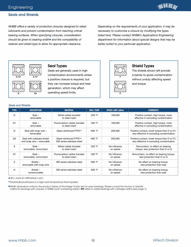
www.nhbb.com 52 HiTech Division
Engineering
Seals and Shields
NHBB offers a variety of protective closures designed to retain
lubricants and prevent contamination from reaching critical
bearing surfaces. When specifying closures, consideration
should be given to bearing width● and the compatibility of
retainer and shield type to allow for appropriate clearance.
Depending on the requirements of your application, it may be
necessary to customize a closure by modifying the types
listed here. Please contact NHBB’s Applications Engineering
department for information about special designs that may be
better suited to your particular application.
Seals and Shields
TYPE DESCRIPTION MATERIAL MAX. TEMP. SPEED LIMIT (dN◆) COMMENTS
D Seal – Nitrile rubber bonded 250 °F 180,000 Positive contact, high torque, most removable to steel insert effective in excluding contamination
D1 Seal – Fluorocarbon rubber bonded 400 °F 180,000 Positive contact, high torque, most removable to steel insert effective in excluding contamination
Q Seal with snap wire – Glass reinforced PTFE* 600 °F 200,000 Positive contact, lower torque than D or D1, removable very effective in excluding contamination
Q4 Seal with outboard shield Glass reinforced PTFE*, 600 °F 200,000 Positive contact, lower torque than D or D1, and snap wire – removable 300 series stainless steel very effective in excluding contamination
S Seal – Nitrile rubber bonded 250 °F No influence Noncontact, no effect on bearing removable, noncontact to steel insert on speed torque, less protection than D or Q
S1 Seal – Fluorocarbon rubber bonded 400 °F No influence Noncontact, no effect on bearing torque, removable, noncontact to steel insert on speed less protection than D or Q
Z Shield – 300 series stainless steel 600 °F No influence No effect on bearing torque, removable with snap wire on speed less protection than seal
H Shield – 300 series stainless steel 600 °F No influence No effect on bearing torque, nonremovable on speed less protection than seal
HS, S1
Q Q4
D, D1
Z
◆dn = bore (in millimeters) x rpm.
*Polytetrafluoroethylene is a high-melt-temperature thermoplastic.
●�Width dimensions noted in the product tables of this Design Guide are for open bearings. Please consult the factory to identify widths for bearings with closures. In nHBB’s part numbering system, RW refers to radial bearings with cartridge widths (see page 7).
Shield TypesThe shields shown left provide
a barrier to gross contamination
without unduly affecting speed
and torque.
Seal TypesSeals are generally used in high
contamination environments where
a positive closure is required, but
they can increase torque and heat
generation, which may affect
operating speed limits.

www.nhbb.com 53 HiTech Division
Engineering
Cage Types
NHBB utilizes numerous cage types consisting of different
materials, manufacturing processes and configurations in order
to satisfy a diverse range of application requirements. A limited
number of standard cage materials such as steel, bronze,
phenolic and nylon are sufficient to cover a broad spectrum of
speeds and operating temperatures. In high speed, high
temperature, and highly corrosive conditions, it may be neces-
sary to specify more specialized materials such as silicon-iron
bronze or steel with silver plating in order to improve perfor-
mance and prolong bearing life. In high load conditions, the
optimal solution may be a full ball complement—or cage-less—
design. While the following information is a good starting point,
our applications engineers are ready to assist you in selecting
the most appropriate cage configuration for your specific
application.
MATERIAL STYLE – PILOTING † DESIGN (FABRICATION MAX. SPEED MAX. OPERATING UTILITY LIMITATIONS TYPICAL POCkET TYPE SURFACE METHOD) [1000 dN◆] TEMP. APPLICATIONS
Steel – Higher speed/ S silver plate 3,000 900 °F (482 °C) strength capability, High cost Mainshafts, (machined) corrosion gear boxes resistant, lubricity
Leaded {80-10-10} 1,000 350 °F (177 °C) Moderate strength/ Moderate cost Pumps and bronze speed capability accessories Land B (machined)
Silicon-iron High speed/ Moderate cost Gear boxes bronze 1,500 500 °F (260 °C) strength capability (machined)
Light weight, high High cost, High reliability, P PEEK● 1,000 500 °F (260 °C) temperature/strength limited aerospace – (molded) capability, tough, availability – power abrasion resistant consult factory transmission
Steel – Higher speed/ S silver plate 3,000 900 °F (482 °C) strength capability, High cost Mainshafts, 1-piece, (machined) corrosion gear boxes rectangular resistant, lubricity pocket Leaded {80-10-10} 1,000 350 °F (177 °C) Moderate strength/ Moderate cost Pumps and Land B bronze speed capability accessories (machined)
Silicon-iron 1,500 500 °F (260 °C) High speed/ Moderate cost Gear boxes No retention bronze strength capability feature Light weight, high High cost, High reliability, P PEEK● 1,000 500 °F (260 °C) temperature/strength limited aerospace – (molded) capability, tough, availability – power abrasion resistant consult factory transmission
Cylindrical Roller Bearings
1-piece, rectangular pocket, with
roller retention
Typical – retention
feature located opposite
piloting surface
Please note: Additional cage designs and materials are available. Please consult the factory for assistance.
† Typical nomenclature that corresponds to material type only. other distinguishing features are defined according to a unique dash number. see Roller Bearing Part numbering system on page 6.
s = steel with silver plate
B = Bronze
P = Plastic
◆dn = bore (in millimeters) x rpm.
●PEEK = Polyetheretherketone, a high-melt-temperature thermoplastic.

www.nhbb.com 54 HiTech Division
Engineering
Cage Types
MATERIAL STYLE – PILOTING † DESIGN (FABRICATION MAX. SPEED MAX. OPERATING UTILITY LIMITATIONS TYPICAL POCkET TYPE SURFACE METHOD) [1000 dN◆] TEMP. APPLICATIONS
Light weight, high High cost, High reliability, Land ME PEEK● 1,000 500 °F (260 °C) temperature/strength limited availability – aerospace – (molded) capability, tough, consult factory power abrasion resistant transmission
Inner KM Phenolic – Quiet running, Limited compatibility, Spindles, high Land linen base 1,500 300 °F (149 °C) porous – can be hygroscopic, speed motors, Outer KV (machined) impregnated with oil outgasses in a robotic joints Land vacuum
PA■ – Quiet running, Low cost/high volume, Motors, MN glass filled 750 300 °F (149 °C) abrasion/impact hygroscopic (3%), spindles, (molded) resistant limited availability – general consult factory purpose
Thin cross section, Power Land MX Bronze▲ 1,500 500 °F (260 °C) higher ball groove High cost transmission, (machined) shoulders, high speed/ aircraft strength capability accessories
Steel – Higher speed/ Higher cost Aircraft M2 silver plate 3,000 900 °F (482 °C) strength capability, accessories, (machined) corrosion high speed resistant, lubricity transmission
Inner MP Leaded Moderate Moderate cost Pumps, Land (80-10-10) 1,000 350 °F (177 °C) speed/strength actuators, Outer MQ bronze capability accessory Land (machined) gear boxes
Inner B5 Silicon-iron High speed/ Higher cost Gear boxes Land bronze 2,000 500 °F (260 °C) strength capability Outer B6 (machined) Land
Inner S3 Steel – Higher speed/ High reliability Land silver plate 3,000 900 °F (482 °C) strength capability, Higher cost mainshaft Outer S4 (machined) corrosion bearings, Land resistant, lubricity gear boxes
Phenolic – Quiet running, Limited compatibility, Outer KS linen base 1,500 300 °F (149 °C) porous – can be hygroscopic, Motors, Land (machined) impregnated outgasses in spindles with oil a vacuum
Angular Contact, Gothic Arch and Fractured Race Ball Bearings
1-piece, cylindrical
1-piece, cylindrical
pocket, with ball retention
Typical – retention feature located
opposite piloting surface
Please note: Additional cage designs and materials are available. Consult the factory for assistance.
† see page 7 for alphanumeric part number code.
◆dn = bore (in millimeters) x rpm.
●PEEK = Polyetheretherketone is a high-melt-temperature thermoplastic.
■PA = Polyamide (a.k.a. nylon or nylon 6/6) is a high-melt-temperature thermoplastic.
▲ Types other than 80-10-10 (leaded bronze) are assigned a special design (sD) number. see Ball Bearing Part numbering system on page 7.

www.nhbb.com 55 HiTech Division
Engineering
Cage Types
MATERIAL STYLE – PILOTING † DESIGN (FABRICATION MAX. SPEED MAX. OPERATING UTILITY LIMITATIONS TYPICAL POCkET TYPE SURFACE METHOD) [1000 dN◆] TEMP. APPLICATIONS
Compact – seal Low to moderate General Land R Steel 150 900 °F (482 °C) or shield clearance, speeds only, purpose, (stamped) low starting high wear rate, industrial Ball RD torque, low cost mis-registration
Compact – seal Moderate speed Land R4 Steel 250 900 °F (482 °C) or shield clearance, capability, Motors, (stamped) low starting high wear rate generators Ball R6 torque, low cost
Inner R5 Land Phosphor Higher speed/ Higher cost, ground bronze 1,000 400 °F (204 °C) strength capability, land (ring) surfaces, Transmission, (stamped) stable – tolerates limited availability – power units higher acceleration consult factory Outer R7 Land
Inner B1 Leaded Land {80-10-10} 1,000 500 °F (260 °C) High speed/ Moderate cost Gear boxes Outer B2 bronze strength capability Land (machined)
Inner S1 Steel – silver Higher speed/ Higher cost – Aircraft engine Land plate 1,500 900 °F (482 °C) strength capability, typically used with gear boxes Outer S2 (machined) corrosion M50 rings and balls Land resistant, lubricity
Phenolic – linen High speed Moderate cost, Starters, Outer M3 base, aluminum 1,000 300 °F (149 °C) capability, can be reduced clearance – generators, Land side plates impregnated with oil typically used with high speed (machined) open bearings motors
Light weight, high Higher cost, High reliability, Ball M8 PEEK● 1,000 500 °F (260 °C) temperature/strength limited availability – aerospace – (molded) capability, abrasion consult factory power resistant transmission
PA■ – Flexible – tolerates Low cost/high volume, Industrial, Ball M7 glass 300 300 °F (149 °C) misalignment, hygroscopic (3%), electric reinforced low noise, abrasion/ limited availability – motors, (molded) impact resistant consult factory munitions
Inner KE Phenolic – Lower mass-less Limited compatibility, Medical, Land linen base 600 300 °F (149 °C) centrifugal deflection, hygroscopic, machine tools, Outer KF (machined) porous – can be outgasses in a rotary joints, Land impregnated with oil vacuum etc.
PA■ – Flexible – tolerates Low cost/high volume, Industrial, Inner M6 glass 300 300 °F (149 °C) misalignment, hygroscopic (3%), electric motors, Land reinforced low noise, abrasion/ limited availability – munitions (molded) impact resistant consult factory
Radial Ball Bearings
2-piece ribbon, spherical pocket
(clinched)
2-piece ribbon, spherical pocket (riveted)
2-piece ribbon, cylindrical
pocket, skirted (riveted)
2-piece, cylindrical
pocket (riveted)
Crown, staggered cylindrical- spherical pocket
Crown, spherical pocket
Crown, cylindrical
Please note: Additional cage designs and materials are available. Consult the factory for assistance.
† see page 7 for alphanumeric part number code.
◆dn = bore (in millimeters) x rpm.●PEEK = Polyetheretherketone is a high-melt-temperature thermoplastic. ■PA = Polyamide (a.k.a. nylon or nylon 6/6) is a high-melt-temperature
thermoplastic.

www.nhbb.com 56 HiTech Division
Selecting the best lubricant for a particular application is critical
to achieving the full rated life of the bearing and optimal
performance of the assembly, but choosing from the hundreds
available can be an overwhelming task. The charts published on
page 57 list a narrow selection of lubricants we use on a regular
basis. They cover a wide range of temperatures, rotational
speeds, load conditions and assembly designs. Please consult
NHBB’s Applications Engineering department before making
your final selection.
Oil LubricantsPetroleum and synthetic oil lubricants are used in conjunction
with a circulating system that maintains the proper oil level and
removes heat from the bearing assembly. While oil is suitable for
a wide range of operating speeds, it is the preferred method of
lubrication for high speed applications. Petroleum oils are still
widely used because of their excellent performance characteris-
tics at normal operating temperatures and medium to high
speeds. Synthetic oils are used in many critical high speed and
high temperature applications because they possess improved
thermal properties, lower volatility and superior viscosity. Syn-
thetic oils encompass a wide spectrum of engineered fluids
including diesters, silicones and fluorinated compounds.
GreaseGrease is ideal for applications where frequent replenishment of
a lubricant is undesirable or impossible. Compared to oil, grease
has a limited speed capability because it does not remove heat
from the bearing and increases torque. Grease consists of a
base oil, thickeners and other additives. The base oil acts as the
lubricating agent while thickeners keep the oil in suspension
before releasing it under pressure. The additives function as anti-
oxidants, rust inhibitors and stabilizers.
Solid FilmSolid film lubricants are used primarily in situations where oil and
grease lubricants would fail, namely in harsh conditions charac-
terized by extremely high or low temperatures, the chance for
radiation exposure or the presence of a vacuum (e.g., space).
Most solid film lubricants possess a finite operating life because
they cannot be replenished once they wear away from the con-
tact surfaces, which make them best suited for light load and low
speed applications. Solid film lubricants encompass everything
from sacrificial retainers to graphite powders, molybdenum-
disulfide powders and ion sputtering. Detailed information on
solid film lubricants has not been provided in this design guide,
as each type must be engineered for the specific application.
Plating and coating materials are typically used to help reduce
surface wear and/or alleviate corrosion. The most widely
specified plating material is Nodular Thin Dense Chrome
(NTDC), more commonly referred to as “Thin Dense Chrome”
or simply “TDC”.
NTDC is a densified, nodular, chromium-rich material. It bonds
to most substrates and is extremely hard (greater than 70 HRC).
The unique micro-nodular surface features help to reduce the
effective contact surface area, thereby lowering friction co-
efficients. The spaces between the nodular formations
(microscopic scale) facilitate improved lubricant retention.
Because of the unique application process, precise geometric
tolerances can be maintained.
Consideration should be given to the processing temperatures.
The NTDC material must be post baked to remove any unwant-
ed hydrogen. Plus, the post bake temperature must be below
the tempering temperature of the ring material to ensure that
dimensional stability and surface hardness are maintained.
Please contact NHBB’s Applications Engineering department
for details relating to other plating and coating options.
Engineering
Lubrication
Platings and Coatings

www.nhbb.com 57 HiTech Division
Engineering
Lubrication
Oil Lubricants
NHBB BRAND NAME TYPE MILITARY OPERATING TEMP. GENERAL COMMENTS CODE SPECIFICATION
LO1 Winsor Lube L-245X Diester MIL-PRF-6085 -65 – 300 °F General purpose instrument oil, low volatility
LO2 Royco® 885 Diester MIL-PRF-6085 -65 – 250 °F General purpose instrument oil, low volatility
LO71 BP Turbo Oil 2389 Diester MIL-PRF-7808 -65 – 300 °F General purpose aircraft lubricant
LY115 Krytox® 143AC Perfluorinated polyether -30 – 550 °F High temperature stability. Vacuum applications
LY223 Braycote® Micronic® 815Z Perfluorinated polyether -112 – 400 °F Wide temperature range. Vacuum applications
LY378 Castrol® 399 Diester MIL-PRF-7808 -65 – 300 °F General purpose aircraft lubricant
LY559 Nye® Synthetic Cyclopentane -45 – 250 °F Special oil for outer space Oil 2001 & high vacuum applications
NHBB BRAND NAME TYPE MILITARY OPERATING TEMP. GENERAL COMMENTS CODE OIL / THICkENER SPECIFICATION
LG4 Aeroshell® 22 PAO/Microgel MIL-PRF-81322 -85 – 400 °F Wide temperature range, good low temp. torque. Aircraft, general purpose. NLGI 2* LG20 Beacon 325 Diester/Lithium complex -65 – 250 °F General purpose instrument grease. NLGI 2* LG49 Aeroshell® 7 Diester/Microgel -100 – 300 °F General purpose, low temp. torque, wide temperature range. NLGI 2* LG68 Royco® 27 Diester/Lithium complex MIL-PRF-23827 -100 – 275 °F General purpose, low temp. torque, wide temperature range. NLGI 2* LY17 Rheotemp® 500 Ester/Sodium complex -65 – 350 °F High speed, high temp. specialty lube. Spindle, instrument, and aircraft bearings. NLGI 2* LY48 Mobilgrease® 28 PAO/Organo-clay MIL-PRF-81322 -65 – 350 °F Wide temperature range, good low temp. torque. Aircraft, general purpose. NLGI 2* LY51 Isoflex® NBU15 Ester/Barium complex -40 – 265 °F High speed, spindle quality grease. NLGI 2* LY101 Krytox® 240AC Perfluorinated/PTFE MIL-PRF-27617 -30 – 550 °F High temperature stability, wide temperature Type III range. Vacuum applications. NLGI 2* LY308 Braycote® 601 EF Perfluorinated/PTFE -112 – 400 °F Wide temperature range. Vacuum applications. NLGI 2* LY548 Rheolube® 2000 Cyclopentane/Sodium -45 – 250 °F Special grease for outer space & complex high vacuum applications
LY660 Polyrex® EM Mineral/Polyurea -20 – 350 °F Electric motor grease. Good high temperature grease. NLGI 2* LY669 Rheolube® 374-C PAO/Lithium complex -40 – 300 °F Channeling type grease, high speed. Good for vertical applications. NLGI 4* LY703 Rheolube® 374-A PAO/Lithium complex -40 – 300 °F General purpose grease. Good speed/temperature range. NLGI 2* LY706 Kluberquiet® Ester/Polyurea -45 – 350 °F Quiet running, wide temperature BQH 72-102 range. NLGI 2*
Grease Lubricants
*national Lubricating Grease Institute number refers to grease thickness.
Registered Trademarks
Aeroshell® – Royal Dutch shell Plc.
Brayco® Micronic®, Castrol® – Castrol Limited.
Isoflex®, Kluberquiet® – Klüber Lubrication, a company of the Freudenberg Group.
Krytox® – DuPont de nemours, Inc.
Mobilgrease®, Polyrex® – Exxon Mobil Corporation.
Royco® – Anderol Company.
nye®, Rheotemp®, Rheolube® – nye Lubricants, Inc.

www.nhbb.com 58 HiTech Division
NHBB manufactures bearings to a variety of ABEC tolerance
levels. Our smaller thin section and torque tube series of
bearings are manufactured to ABEC 5T and 7T tolerances as
described in ABMA Std. 12.2. Larger diameter thin cross
section bearings are manufactured to ABEC 1F, 3F, 5F or 7F
tolerances as noted in ABMA Std. 26.2, and our metric series
bearings are manufactured to ABEC/RBEC 1, 3, 5 or 7 toler-
ances as outlined in ABMA Std. 20.
The choice of precision level is dependent on the requirements
of the application. The lower classes (ABEC 1 and 3) are
suitable for applications with lower speed and accuracy needs.
These bearings provide a more favorable cost-to-performance
ratio. Applications with the need for higher speed, lower
torque or greater positional accuracy will most likely require
higher precision grades. Please contact NHBB’s Applications
Engineering department for assistance in selecting the proper
tolerance class.
Engineering
Tolerances
Inner Ring
Outer Ring
TOLERANCES IN INCHES
Ring Width Bore Size Bore Diameter Tolerance Radial Runout Maximum ABEC ABEC Duplex (mm) ABEC/RBEC Class ABEC/RBEC Class 1 & 3 5, 7 & 9
OVER INCL. 1 3 5 7 9 1 3 5 7 9 SINGLE SINGLE INDIVIDUAL RING
— 10 .00030 .00030 .00020 .00015 .00010 .00040 .00025 .00015 .00010 .00005 .0047 .0016 .0098
10 18 .00030 .00030 .00020 .00015 .00010 .00040 .00030 .00015 .00010 .00005 .0047 .0031 .0098
18 30 .00040 .00030 .00025 .00020 .00010 .00050 .00030 .00015 .00010 .00010 .0047 .0047 .0098
30 50 .00045 .00040 .00030 .00025 .00010 .00060 .00040 .00020 .00015 .00010 .0047 .0047 .0098
50 80 .00060 .00045 .00035 .00030 .00015 .00080 .00040 .00020 .00015 .00010 .0059 .0059 .0098
80 120 .00080 .00060 .00040 .00030 .00020 .00100 .00050 .00025 .00020 .00010 .0079 .0079 .0150
120 180 .00100 .00070 .00050 .00040 .00030 .00120 .00070 .00030 .00025 .00015 .0098 .0098 .0150
180 250 .00120 .00085 .00060 .00045 .00030 .00160 .00080 .00040 .00030 .00020 .0118 .0118 .0197
TOLERANCES IN INCHES
Ring Width Bore Size Bore Diameter Tolerance Radial Runout Maximum ABEC ABEC Duplex (mm) ABEC/RBEC Class ABEC/RBEC Class 1 & 3 5, 7 & 9
OVER INCL. 1 3 5 7 9 1 3 5 7 9 SINGLE SINGLE INDIVIDUAL RING
18 30 .00035 .00030 .00025 .00020 .00015 .00060 .00035 .00025 .00015 .00010 .0047 .0016 .0098
30 50 .00045 .00035 .00030 .00025 .00015 .00080 .00040 .00030 .00020 .00010 .0047 .0031 .0098
50 80 .00050 .00045 .00035 .00030 .00015 .00100 .00050 .00030 .00020 .00015 .0047 .0047 .0098
80 120 .00060 .00050 .00040 .00030 .00020 .00140 .00070 .00040 .00025 .00020 .0047 .0047 .0098
120 150 .00070 .00060 .00045 .00035 .00020 .00160 .00080 .00045 .00030 .00020 .0059 .0059 .0098
150 180 .00100 .00070 .00050 .00040 .00030 .00180 .00090 .00050 .00030 .00020 .0079 .0079 .0150
180 250 .00120 .00080 .00060 .00045 .00030 .00200 .00100 .00060 .00040 .00030 .0098 .0098 .0150
250 315 .00140 .00100 .00070 .00050 .00030 .00240 .00120 .00070 .00045 .00030 .0118 .0118 .0197
Please note: Industry standards for tolerances are issued and maintained by the American Bearing Manufacturers Association (ABMA), of which nHBB is an active member. standards are established with input from ABMA associated bearing technical committees, Annular Bearing Engineers’ Committee (ABEC), Roller Bearing Engineers’ Committee (RBEC), and engineers and managers from member bearing manufacturers.

www.nhbb.com 59 HiTech Division
DEvIATION FROM BALL GRADE BALL LOT DIAMETER STEEL CERAMIC (0.000001 IN.)
G3A 3C 5
G5A 5C 10
G10A 10C 20
G16A 16C 32
G24A 24C 48
vARIATION OF DEvIATION FROM SURFACE ROUGHNESS BALL GRADE BALL DIAMETER SPHERICAL FORM RA MAX. STEEL CERAMIC (0.000001 IN.) (0.000001 IN.) STEEL CERAMIC
G3A 3C 3 3 0.40 0.15
G5A 5C 5 5 0.56 0.20
G10A 10C 10 10 0.80 0.25
G16A 16C 16 16 1.00 0.35
G24A 24C 24 24 2.60 0.50
Engineering
Ball Grades
Balls are manufactured to the precision requirements noted in
ANSI/ABMA Std. 10A for steel balls and ASTM F2094 for
ceramic balls. These standards require that balls meet the limits
for ball diameter, spherical form and roughness noted below for
each grade level. Lower grade numbers denote more precise
balls, which help to improve accuracy, reduce running torque,
lengthen lube life and reduce noise. With few exceptions,
NHBB manufactures its precision bearings with grade 10A
and 10C balls or better.
Individual Balls Lots
Engineered specifically for bearings, silicon nitride (ceramic)
balls possess highly controlled, consistent geometry and
extremely smooth and consistent surface finish. The stiffness,
light weight and inertness of silicon nitride balls offer significant
bearing performance advantages, including higher operating
speeds, lower heat generation, extended bearing life and
expanded design possibilities for unique and demanding
bearing applications. In addition, the dissimilar materials
between the ceramic balls and the steel rings minimize cold
welding and adhesive wear. Ceramic balls are particularly well
suited for high speed applications and in situations where
marginal lubrication is a possibility.
Specifications
Performance Benefits
MATERIAL SPECIFICATIONS ATTRIBUTES ROOM TEMP. HARDNESS
Silicon nitride ASTM F2094 Extended life, lower >1380 HV10 torque, lighter weight, (>78 HRC) higher stiffness
PROPERTIES IMPROvEMENT IN BEARING PERFORMANCE
Lower internal friction Lower internal temperature Reduced cage and raceway wear
Lighter weight Lighter overall bearing weight 58% lighter than steel Decreased centrifugal force Decreased gyroscopic movement
Higher stiffness & higher hardness Reduced skidding Less friction Lower operating temperatures Less wear
Smoother surface Decreased lube degradation 65% smoother than steel No cold welding/adhesive wear Less friction Lower operating temperature Less wear
Corrosion resistance Durability in harsh environments Less wear Resists galling
Higher maximum temperature Wider operating range
Typical Applications• Micro turbines (power generation)
• Aircraft instrumentation
• Gas turbine engines
• Hot air valves
• Helicopter gear boxes
• Accessory gear boxes
Silicon Nitride Balls

www.nhbb.com 60 HiTech Division
Engineering
Engineering Analysis and Reporting
HiTech’s ball and roller bearings have a solid reputation for qual-
ity, reliability and consistency. However, bearings—like any
mechanical device—are subject to serviceability issues. Failure
may occur due to improper mounting, lubrication, environment,
loading, maintenance, or contamination after installation.
NHBB has a versatile technical staff with extensive experience
in the analysis of ball and roller bearings in the event of failure.
Using specialized knowledge, analytical tools and precision
measuring and testing equipment, the cause for bearing failure
can often be determined quickly and succinctly.
RequirementsSpecific hardware and/or information is required to successfully
perform a bearing analysis:
• All bearing hardware, preferably in the assembled state as
removed from the application with minimal disruption;
• Installation information, including interfacing hardware details,
materials and fit-up;
• Bearing serial numbers and manufacturing lot numbers, if
available;
• Historical information describing the conditions under which
the bearings operated, including speeds, loads, temperatures
and atmospheric conditions, as well as any unusual shock,
vibration, electrical arcing or handling situations to which the
bearing was subjected.
When service or failure analysis is required, please contact
NHBB’s Applications Engineering department.
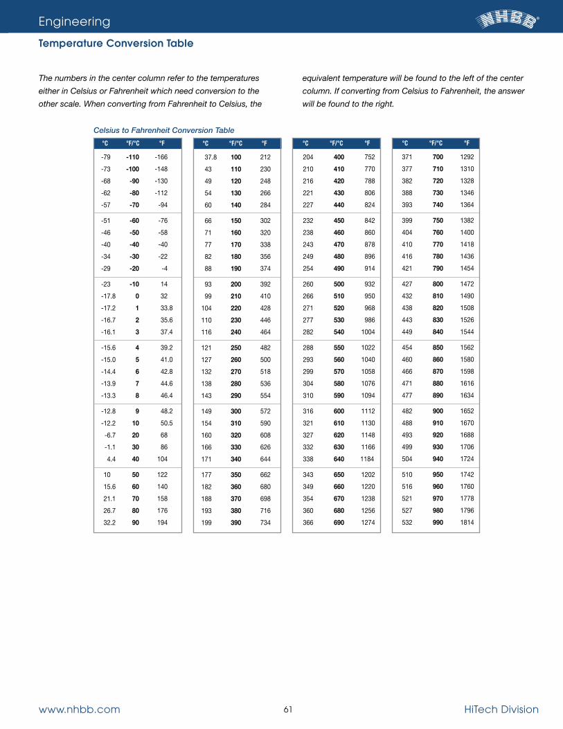
HiTech Division61www.nhbb.com
°C
37.8
43
49
54
60
66
71
77
82
88
93
99
104
110
116
121
127
132
138
143
149
154
160
166
171
177
182
188
193
199
°F/°C
100
110
120
130
140
150
160
170
180
190
200
210
220
230
240
250
260
270
280
290
300
310
320
330
340
350
360
370
380
390
°F
212
230
248
266
284
302
320
338
356
374
392
410
428
446
464
482
500
518
536
554
572
590
608
626
644
662
680
698
716
734
°C
204
210
216
221
227
232
238
243
249
254
260
266
271
277
282
288
293
299
304
310
316
321
327
332
338
343
349
354
360
366
°F/°C
400
410
420
430
440
450
460
470
480
490
500
510
520
530
540
550
560
570
580
590
600
610
620
630
640
650
660
670
680
690
°F
752
770
788
806
824
842
860
878
896
914
932
950
968
986
1004
1022
1040
1058
1076
1094
1112
1130
1148
1166
1184
1202
1220
1238
1256
1274
°C
371
377
382
388
393
399
404
410
416
421
427
432
438
443
449
454
460
466
471
477
482
488
493
499
504
510
516
521
527
532
°F/°C
700
710
720
730
740
750
760
770
780
790
800
810
820
830
840
850
860
870
880
890
900
910
920
930
940
950
960
970
980
990
°F
1292
1310
1328
1346
1364
1382
1400
1418
1436
1454
1472
1490
1508
1526
1544
1562
1580
1598
1616
1634
1652
1670
1688
1706
1724
1742
1760
1778
1796
1814
Engineering
Temperature Conversion Table
The numbers in the center column refer to the temperatures
either in Celsius or Fahrenheit which need conversion to the
other scale. When converting from Fahrenheit to Celsius, the
equivalent temperature will be found to the left of the center
column. If converting from Celsius to Fahrenheit, the answer
will be found to the right.
°C
-79
-73
-68
-62
-57
-51
-46
-40
-34
-29
-23
-17.8
-17.2
-16.7
-16.1
-15.6
-15.0
-14.4
-13.9
-13.3
-12.8
-12.2
-6.7
-1.1
4.4
10
15.6
21.1
26.7
32.2
°F/°C
-110
-100
-90
-80
-70
-60
-50
-40
-30
-20
-10
0
1
2
3
4
5
6
7
8
9
10
20
30
40
50
60
70
80
90
°F
-166
-148
-130
-112
-94
-76
-58
-40
-22
-4
14
32
33.8
35.6
37.4
39.2
41.0
42.8
44.6
46.4
48.2
50.5
68
86
104
122
140
158
176
194
Celsius to Fahrenheit Conversion Table

www.nhbb.com 62 HiTech Division
Engineering
Inch/Metric Conversion Table
Fraction Decimal Decimal Inch Inch mm
1/64 0.01563 0.3969
1/32 0.03125 0.7938
3/64 0.04688 1.1906
1/16 0.06250 1.5875
5/64 0.07813 1.9844
3/32 0.09375 2.3813
7/64 0.10938 2.7781
1/8 0.12500 3.1750
9/64 0.14063 3.5719
5/32 0.15625 3.9688
11/64 0.17188 4.3656
3/16 0.18750 4.7625
13/64 0.20313 5.1594
7/32 0.21875 5.5563
15/64 0.23438 5.9531
1/4 0.25000 6.3500
17/64 0.26563 6.7469
9/32 0.28125 7.1438
5/16 0.31250 7.9375
11/32 0.34375 8.7313
3/8 0.37500 9.5250
13/32 0.40625 10.3188
7/16 0.43750 11.1125
15/32 0.46875 11.9063
1/2 0.50000 12.7000
7/64 0.10938 2.7781
17/32 0.53125 13.4938
9/16 0.56250 14.2875
19/32 0.59375 15.0813
5/8 0.62500 15.8750
11/16 0.68750 17.4625
3/4 0.75000 19.0500
13/16 0.81250 20.6375
7/8 0.87500 22.2250
15/16 0.93750 23.8125
1 1.00000 25.4000
1-1/16 1.06250 26.9875
1-1/8 1.12500 28.5750
1-3/16 1.18750 30.1625
1-1/4 1.25000 31.7500
1-5/16 1.31250 33.3375
Fractional to Decimal Conversions
mm 0 10 20 30 40 50
0 0.00000 0.39370 0.78740 1.18110 1.57480 1.96850
1 0.03937 0.43307 0.82677 1.22047 1.61417 2.00787
2 0.07874 0.47244 0.86614 1.25984 1.65354 2.04724
3 0.11811 0.51181 0.90551 1.29921 1.69291 2.08661
4 0.15748 0.55118 0.94488 1.33858 1.73228 2.12598
5 0.19685 0.59055 0.98425 1.37795 1.77165 2.16535
6 0.23622 0.62992 1.02362 1.41732 1.81102 2.20472
7 0.27559 0.66929 1.06299 1.45669 1.85039 2.24409
8 0.31496 0.70866 1.10236 1.49606 1.88976 2.28346
9 0.35433 0.74803 1.14173 1.53543 1.92913 2.32283
mm 60 70 80 90 100 110
0 2.36220 2.75591 3.14961 3.54331 3.93701 4.33071
1 2.40157 2.79528 3.18898 3.58268 3.97638 4.37008
2 2.44094 2.83465 3.22835 3.62205 4.01575 4.40945
3 2.48031 2.87402 3.26772 3.66142 4.05512 4.44882
4 2.51969 2.91339 3.30709 3.70079 4.09449 4.48819
5 2.55906 2.95276 3.34646 3.74016 4.13386 4.52756
6 2.59843 2.99213 3.38583 3.77953 4.17323 4.56693
7 2.63780 3.03150 3.42520 3.81890 4.21260 4.60630
8 2.67717 3.07087 3.46457 3.85827 4.25197 4.64567
9 2.71654 3.11024 3.50394 3.89764 4.29134 4.68504
mm 120 130 140 150 160 170
0 4.72441 5.11811 5.51181 5.90551 6.29921 6.69291
1 4.76378 5.15748 5.55118 5.94488 6.33858 6.73228
2 4.80315 5.19685 5.59055 5.98425 6.37795 6.77165
3 4.84252 5.23622 5.62992 6.02362 6.41732 6.81102
4 4.88189 5.27559 5.66929 6.06299 6.45669 6.85039
5 4.92126 5.31496 5.70866 6.10236 6.49606 6.88976
6 4.96063 5.35433 5.74803 6.14173 6.53543 6.92913
7 5.00000 5.39370 5.78740 6.18110 6.57480 6.96850
8 5.03937 5.43307 5.82677 6.22047 6.61417 7.00787
9 5.07874 5.47244 5.86614 6.25984 6.65354 7.04724
mm 180 190 200 210 220 230
0 7.08661 7.48031 7.87402 8.26772 8.66142 9.05512
1 7.12598 7.51969 7.91339 8.30709 8.70079 9.09449
2 7.16535 7.55906 7.95276 8.34646 8.74016 9.13386
3 7.20472 7.59843 7.99213 8.38583 8.77953 9.17323
4 7.24409 7.63780 8.03150 8.42520 8.81890 9.21260
5 7.28346 7.67717 8.07087 8.46457 8.85827 9.25197
6 7.32283 7.71654 8.11024 8.50394 8.89764 9.29134
7 7.36220 7.75591 8.14961 8.54331 8.93701 9.33071
8 7.40157 7.79528 8.18898 8.58268 8.97638 9.37008
9 7.44094 7.83465 8.22835 8.62205 9.01575 9.40945
Millimeters to Inches
Example: To look up the inch equivalent of 15 mm, find 10 on
the horizontal axis and 5 on the vertical axis. Their intersection
is the inch equivalent. 15 mm = .59055 inch. 1 inch = 25.4 mm.

www.nhbb.com 63 HiTech Division
COMMITTED TO ExCELLENCEWe continue to build strong alliances within the aerospace, medical/dental and high
tech industries, working across the enterprise to provide business solutions that keep
pace with our customers’ technological advances.
The precision tolerances required by the customers we support necessitate a complete
commitment to quality. At NHBB, that commitment is apparent in everything we do,
from an investment in advanced capabilities, to real-time quality control, to continuous
improvement in both processes and people. Our commitment to manufacturing
excellence is seen time and again in our high level of service and product quality.
APPLICATIONS ENGINEERINGKnowing how to leverage knowledge, industry experience, emerging technology
and industry trends is the true differentiator when it comes to customized bearing
assemblies. At NHBB, we offer complete bearing engineering support for every phase
of a product’s life cycle, and we do this with a passion for serving as a vital technical
resource to our customers.
MANUFACTURINGInvesting in the most advanced technologies available gives NHBB a significant
advantage in precision manufacturing. We’re able to guarantee the close tolerances
necessary in life-critical and high speed applications, as well as address manufacturing
challenges in-house through new tools, precision gages and state-of-the-art produc-
tion processes.
CARE FOR THE ENVIRONMENTAt NHBB, our stringent environmental policy emphasizes pollution prevention,
regulatory compliance, and continuous improvement aimed at reducing the impact of
every phase of the manufacturing process. Our objectives also include the promotion
of environmental awareness among employees and within our communities.
new Hampshire Ball Bearings, Inc.
Company Overview
HiTech Division63www.nhbb.com
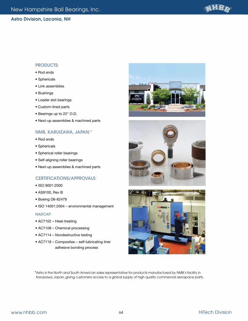
www.nhbb.com 64 HiTech Division
new Hampshire Ball Bearings, Inc.
Astro Division, Laconia, NH
PRODUCTS:• Rod ends
• Sphericals
• Link assemblies
• Bushings
• Loader slot bearings
• Custom-lined parts
• Bearings up to 22" O.D.
• Next-up assemblies & machined parts
NMB, KARUIzAWA, JAPAN:*• Rod ends
• Sphericals
• Spherical roller bearings
• Self-aligning roller bearings
• Next-up assemblies & machined parts
CERTIFICATIONS/APPROVALS: • ISO 9001:2000
• AS9100, Rev B
• Boeing D6-82479
• ISO 14001:2004 – environmental management
NADCAP:
• AC7102 – Heat-treating
• AC7108 – Chemical processing
• AC7114 – Nondestructive testing
• AC7118 – Composites – self-lubricating liner
adhesive bonding process
* Astro is the north and south American sales representative for products manufactured by nMB’s facility in Karuizawa, Japan, giving customers access to a global supply of high quality commercial aerospace parts.

www.nhbb.com 65 HiTech Division
new Hampshire Ball Bearings, Inc.
Precision Division, Chatsworth, CA Keeping Technology on the Move®
PRODUCTS:• Ultra-precision miniature & instrument
ball bearings
– Inch and metric
– Hybrid ceramics
– Torque tube/thin section
– Duplex/super duplex
• Airframe control bearings
• Modified dimensions
– Special bore, O.D. and width
– Custom designs
• Machined cages
– Phenolic, Torlon®,
Delrin®, Meldin®
• Mechanical assemblies
• Middle size bearings (up to 3" O.D.)
CERTIFICATIONS/APPROVALS:
• ISO 9001:2000
• AS9100, Rev B
• ISO 14001:2004 – environmental management
NADCAP:
• AC7102 – Heat-treating

www.nhbb.com 66 HiTech Division
new Hampshire Ball Bearings, Inc.
myonic usa, Chatsworth, CA
PRODUCTS:• Ultra precision miniature ball bearings
– Deep groove radial
– Angular contact
– Full line of metric
• Thrust bearings
• X-ray tube bearings
• Aircraft instrument bearings
• Dental bearings
– Integral shaft
– Complete turbine assemblies
– Laser welded shields
– Hybrid ceramic
– Spindles/auto chucks
• Shims and washers
• Customized bearing systems
• Contract manufactured products
CERTIFICATION: • ISO 9001:2008

www.nhbb.com 67 HiTech Division
new Hampshire Ball Bearings, Inc.
Minebea Co., Ltd.
New Hampshire Ball Bearings is an integral part of an international
business. Its parent company, Minebea Co., Ltd., is the world’s leading
specialized manufacturer of miniature ball bearings and high precision
components for the telecommunications, aerospace, automotive and
electrical appliance industries.
The Minebea Group is comprised of 40 subsidiaries in 16 countries,
and employs 44,000 people. In addition to its worldwide manufacturing
capabilities, Minebea’s vision is to lead the competition through exten-
sive research and development of new methods and technologies.


HiTech Division 175 Jaffrey Road
Peterborough, NH 03458 tel: 603.924.4100 fax: 603.924.9302
Precision Division andCorporate Headquarters9700 Independence Avenue
Chatsworth, CA 91311 tel: 818.993.4100 fax: 818.407.5020
Astro Division 155 Lexington Drive Laconia, NH 03246
tel: 603.524.0004 fax: 603.524.9025
myonic usa
9700 Independence AvenueChatsworth, CA 91311
tel: 818.701.4833 fax: 818.407.5020
NHBB Europe
Siemensstrasse 30 63225 Langen
Germany tel: (49) 6103.913.341 fax: (49) 6103.913.342
www.nhbb.com
© 2010 NHBB, Inc.