role of tundish argon diffuser in steelmaking …...role of tundish argon diffuser in steelmaking...
TRANSCRIPT
Role of Tundish Argon Diffuser in Steelmaking Tundish to
Improve Inclusion Flotation with CFD and Water
Modelling Studies
Sujata Devi, Rajeev Kumar Singh, &Amitava Paul
RDCIS, SAIL,
Ranchi-834002
Abstract - Investigation on inclusion removal by bubble flotation
method in a two-strand tundish was carried out using
computational fluid dynamics and through water model studies.
Recently, a new technique of gas curtain made of small bubbles
of argon called Tundish Argon Diffuser has been used to
remove the finer inclusions from steel in order to produce clean
steel. Aim of this work was to find out the effect Tundish Argon
Diffuser on the efficiency of inclusions removal and on
optimization of its location for plant conditions. Both Physical
and Numerical simulations were carried out in a 1:4 scaled
down model for tundish of 50T capacity of Bokaro Steel Plant,
India. Numerical simulations were carried out using ANSYS
FLUENT CFD software. For physical modeling study, water
model was used for fluid flow, residence time distribution and
inclusion flotation studies. Results from both studies suggested
that the use of tundish argon diffuser enhances the surface
directed flow which in turn improves inclusion flotation and
also reduces metal loss due to better mixing and lesser dead
zone. Fluid flow analysis showed lesser turbulence on the free
surface which lead to lesser de-oxidation of liquid steel after
using Tundish Argon Diffuser. Location of Tundish Argon
Diffuser needs to be optimized in order to get maximum benefit.
For Bokaro Steel Plant conditions, placement of Tundish Argon
Diffuser at 2400mm at both sides from the center gives the best
result compared to all other locations.
Keywords: Computational Fluid Dynamics, Water modeling,
Tundish, RTD analysis, Inclusion flotation
1. INTRODUCTION
The steel tundish in continuous casting not only acts as a
storage vessel, but also acts as an additional metallurgical
unit where other operations such as control of melt
temperature, composition etc. and melt flow control are
performed in order to promote non metallic inclusion
separation. Increasing demands from customer for the
production of high-quality steels, led to the development of
new technologies in tundish for removal of inclusions from
liquid steel. Non-metallic inclusions, such as sulphide,
silicate and aluminates particles, are formed during the
steelmaking process. If these inclusions are large enough and
are entrapped within the steel melt they often lead to
undesirable defects in steel products. For steel to be termed
‘clean’, it must have a low level of residuals. The dynamics
of melt flow is a key factor in controlling the inclusions
flotation. Non-metallic inclusions of sizes smaller than 15
µm are difficult to remove, as they do not float easily. They
are carried by the flow of steel melt into the mould which
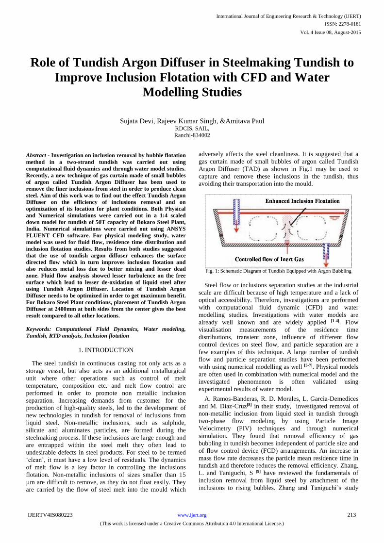
adversely affects the steel cleanliness. It is suggested that a
gas curtain made of small bubbles of argon called Tundish
Argon Diffuser (TAD) as shown in Fig.1 may
be used to
capture and remove these inclusions in the tundish, thus
avoiding their transportation into the mould.
Fig. 1: Schematic Diagram of Tundish Equipped with Argon Bubbling
Steel flow or inclusions separation studies at the industrial
scale are difficult
because of high
temperature and a lack of
optical accessibility. Therefore, investigations are performed
with computational fluid dynamic (CFD)
and water
modelling
studies. Investigations with water models are
already well known and are widely applied [1-4]. Flow
visualisation measurements of the residence time
distributions, transient zone, influence of different flow
control devices on steel flow, and particle separation are a
few examples
of this technique. A large number of tundish
flow and particle separation studies
have been performed
with using numerical modelling as well [5-7]. Physical models
are often used in combination with numerical
model and the
investigated phenomenon is
often validated using
experimental results of water model.
A. Ramos-Banderas, R. D. Morales, L. Garcia-Demedices
and M. Diaz-Cruz[8] in their study, investigated removal of
non-metallic inclusion from liquid steel in tundish through
two-phase flow modeling by using Particle Image
Velocimetry (PIV) techniques and through numerical
simulation. They found that removal efficiency of gas
bubbling in tundish becomes independent of particle size and
of flow control device (FCD) arrangements. An increase in
mass flow rate decreases the particle mean residence time in
tundish and therefore reduces the removal efficiency. Zhang,
L. and Taniguchi, S [9] have reviewed the fundamentals of
inclusion removal from liquid steel by attachment of the
inclusions to rising bubbles. Zhang and Taniguchi’s study
International Journal of Engineering Research & Technology (IJERT)
ISSN: 2278-0181
www.ijert.orgIJERTV4IS080223
(This work is licensed under a Creative Commons Attribution 4.0 International License.)
Vol. 4 Issue 08, August-2015
213

provides an overview of the mechanisms of bubble/inclusion
interaction and also provided a model for inclusion removal
by bubbling in batch processes like ladle stirring. J. de J.
Barreto S., M. A Barron MEZA, and R D Morales[10] have
proposed that bubbling in a tundish could remove small
inclusions. A cold model study on inclusion removal has
demonstrated that fine particles can be readily sensitive to
fluid depth, casting rate, and gas flow rate & bubbler
position. A numerical model has been developed to predict
the effect to the above parameters on inclusion removal.
The present study investigates the effect of Tundish Argon
Diffuser on the efficiency of inclusion removal inside the
tundish. Both CFD and water modelling studies have been
carried out in a 1:4 scaled down model for tundish of 50T
capacity of Bokaro Steel Plant (BSL). Numerical simulations
were carried out using ANSYS FLUENT CFD software. For
water modelling study, water model was used to
observe/measure the fluid flow, residence time distribution
and inclusion flotation.
2. CFD MODELING
Numerical simulations were carried out using ANSYS
FLUENT CFD [1] software. For convenience and for better
understanding, numerical model studies have been
summarized under following three main headings.
Fluid Flow
Residence Time Distributions, and
Inclusion Transport and Separation.
Fig. 2 shows the dimensions and meshed geometry of
tundish which was used for simulation studies. Fluid flow
has been simulated using k- turbulent model, species
transport technique has been used for residence time
distribution (RTD) analysis and discrete phase model (DPM)
technique has been utilised to investigate inclusion flotation.
Material properties of the liquid steel and modelling
parameters used in the numerical simulation are given in the
Table-1.
Fig. 2: Dimensions and meshed geometry of Tundish (in mm)
Table 1: Physical Properties of Liquid Steel and Modeling Parameter
Property Value Unit
Density 7000 Kg/m3
Molecular Viscosity 0.00555 Kgm-1s-1
Inclusion density 3500 Kg/m3
Parameters
Mass flow rate in actual tundish 36.5 Kg/s
Mass flow rate in model tundish 1.2375 Kg/s
2.1 Governing Equations
a) Fluid Flow
The numerical model designed for the simulation of liquid
steel flow in the tundish will include differential equations of
continuity of flow and conservation of momentum. The flow
profile of the tundish in the present study is calculated using
standard turbulent equations of the k- model expressed in
their three-dimensional version with standard wall
functions[2].
Continuity equation can be expressed as eq.(1)
0)(
i
i
Uxt
(1)
In any flow (viz. Oxygen furnace, ladle, tundish etc.) the
balances among the various forces acting on a fluid element
can be described by the Navier-Stokes equation. For single
phase, 3D flows in mettaturgical tundishes operating under
steady state, isothermal, turbulent flow condition, the
momentum balance on an elementary volume of liquid steel
can be expressed as given below in eq(2), with two equations
for turbulent kinetic energy and turbulent dissipation rate in
eq(3) & eq(4) respectively.
i
i
j
i
i
eff
iii
jii gx
u
x
u
xx
P
x
uu
t
u
)(
)()( (2)
k
ik
t
i
Gx
k
xt
k
(3)
kCG
kC
xxtk
i
t
i
2
21
(4)
The effective co-efficient of viscosity is expressed by the
formula below
tffe (5)
Where the dynamic coefficient of turbulent viscosity is
defined by the formula
2kCt
(6)
Where the production term of turbulent energy is equal to
i
j
j
i
i
j
tx
u
x
u
x
uG
(7)
Constants used in the k-e model[1] (Launder and Spalding,
1974) are given in the table-2.
International Journal of Engineering Research & Technology (IJERT)
ISSN: 2278-0181
www.ijert.orgIJERTV4IS080223
(This work is licensed under a Creative Commons Attribution 4.0 International License.)
Vol. 4 Issue 08, August-2015
214
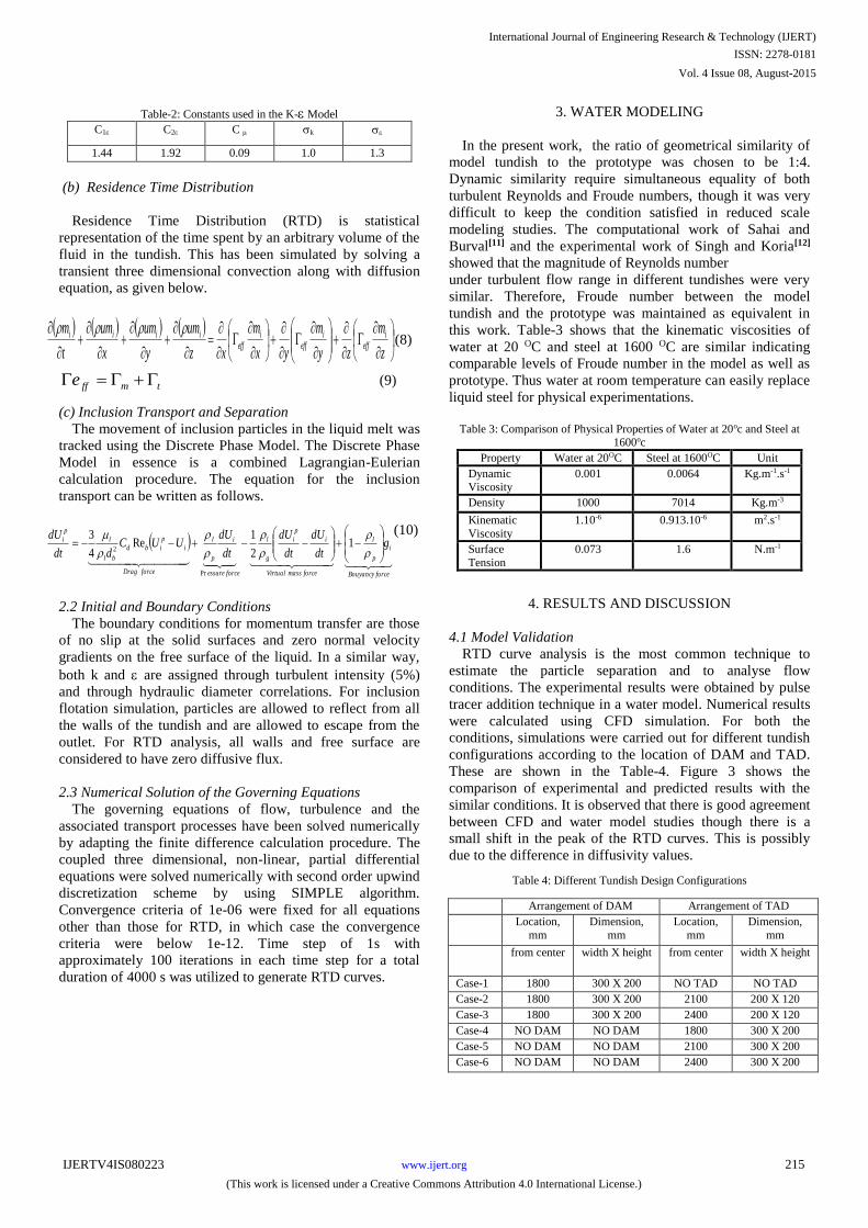
Table-2: Constants used in the K- Model
C1 C2 C k
1.44 1.92 0.09 1.0 1.3
(b) Residence Time Distribution
Residence Time Distribution (RTD) is statistical
representation of the time spent by an arbitrary volume of the
fluid in the tundish. This has been simulated by solving a
transient three dimensional convection along with diffusion
equation, as given below.
z
m
zy
m
yx
m
xz
um
y
um
x
um
t
m ieff
ieff
ieff
iiii (8)
tmffe (9)
(c) Inclusion Transport and Separation
The movement of inclusion particles in the liquid melt was
tracked using the Discrete Phase Model. The Discrete Phase
Model in essence is a combined Lagrangian-Eulerian
calculation procedure. The equation for the inclusion
transport can be written as follows.
forceBouyancy
i
p
l
forcemassVirtual
i
p
i
g
l
forceessure
i
p
l
forceDrag
i
p
ibd
bl
l
p
i gdt
dU
dt
dU
dt
dUUUC
ddt
dU
1
2
1Re
4
3
Pr
2
(10)
2.2 Initial and Boundary Conditions
The boundary conditions for momentum transfer are those
of no slip at the solid surfaces and zero normal velocity
gradients on the free surface of the liquid. In a similar way,
both k and are assigned through turbulent intensity (5%)
and through hydraulic diameter correlations. For inclusion
flotation simulation, particles are allowed to reflect from all
the walls of the tundish and are allowed to escape from the
outlet. For RTD analysis, all walls and free surface are
considered to have zero diffusive flux.
2.3 Numerical Solution of the Governing Equations
The governing equations of flow, turbulence and the
associated transport processes have been solved numerically
by adapting the finite difference calculation procedure. The
coupled three dimensional, non-linear, partial differential
equations were solved numerically with second order upwind
discretization scheme by using SIMPLE algorithm.
Convergence criteria of 1e-06 were fixed for all equations
other than those for RTD, in which case the convergence
criteria were below 1e-12. Time step of 1s with
approximately 100 iterations in each time step for a total
duration of 4000 s was utilized to generate RTD curves.
3. WATER MODELING
In the present work, the ratio of geometrical similarity of
model tundish to the prototype was chosen to be 1:4.
Dynamic similarity require simultaneous equality of both
turbulent Reynolds and Froude numbers, though it was very
difficult to keep the condition satisfied in reduced scale
modeling studies. The computational work of Sahai and
Burval[11] and the experimental work of Singh and Koria[12]
showed that the magnitude of Reynolds number
under turbulent flow range in different tundishes were very
similar. Therefore, Froude number between the model
tundish and the prototype was maintained as equivalent in
this work. Table-3 shows that the kinematic viscosities of
water at 20 OC and steel at 1600 OC are similar indicating
comparable levels of Froude number in the model as well as
prototype. Thus water at room temperature can easily replace
liquid steel for physical experimentations.
Table 3: Comparison of Physical Properties of Water at 20oc and Steel at
1600oc
Property Water at 20OC Steel at 1600OC Unit
Dynamic Viscosity
0.001 0.0064 Kg.m-1.s-1
Density 1000 7014 Kg.m-3
Kinematic
Viscosity
1.10-6 0.913.10-6 m2.s-1
Surface
Tension
0.073 1.6 N.m-1
4. RESULTS AND DISCUSSION
4.1 Model Validation
RTD curve analysis is the most common technique to
estimate the particle separation and to analyse flow
conditions. The experimental results were obtained by pulse
tracer addition technique in a water model. Numerical results
were calculated using CFD simulation. For both the
conditions, simulations were carried out for different tundish
configurations according to the location of DAM and TAD.
These are shown in the Table-4. Figure 3 shows the
comparison of experimental and predicted results with the
similar conditions. It is observed that there is good agreement
between CFD and water model studies though there is a
small shift in the peak of the RTD curves. This is possibly
due to the difference in diffusivity values.
Table 4: Different Tundish Design Configurations
Arrangement of DAM Arrangement of TAD
Location,
mm
Dimension,
mm
Location,
mm
Dimension,
mm
from center width X height from center width X height
Case-1 1800 300 X 200 NO TAD NO TAD
Case-2 1800 300 X 200 2100 200 X 120
Case-3 1800 300 X 200 2400 200 X 120
Case-4 NO DAM NO DAM 1800 300 X 200
Case-5 NO DAM NO DAM 2100 300 X 200
Case-6 NO DAM NO DAM 2400 300 X 200
International Journal of Engineering Research & Technology (IJERT)
ISSN: 2278-0181
www.ijert.orgIJERTV4IS080223
(This work is licensed under a Creative Commons Attribution 4.0 International License.)
Vol. 4 Issue 08, August-2015
215
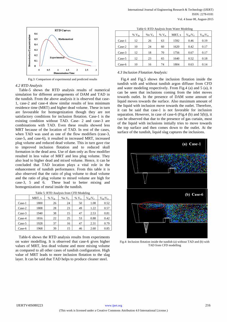
Fig.3: Comparison of experimental and predicted results
4.2 RTD Analysis
Table-5 shows the RTD analysis results of numerical
simulation for different arrangements of DAM and TAD in
the tundish. From the above analysis it is observed that case-
1, case-2 and case-4 show similar results of less minimum
residence time (MRT) and higher dead volume. These in turn
are favourable for homogenization though they are not
satisfactory conditions for inclusion flotation. Case-1 is the
existing condition without TAD. Case- 2 and case-3 are
combinations with TAD. Even these results showed less
MRT because of the location of TAD. In rest of the cases,
when TAD was used as one of the flow modifiers (case-3,
case-5, and case-6), it resulted in increased MRT, increased
plug volume and reduced dead volume. This in turn gave rise
to improved inclusion flotation and to reduced skull
formation in the dead area. Use of dam only as flow modifier
resulted in less value of MRT and less plug volume. They
also lead to higher dead and mixed volume. Hence, it can be
concluded that TAD location plays a vital role in the
enhancement of tundish performance. From this table it is
also observed that the ratio of plug volume to dead volume
and the ratio of plug volume to mixed volume are high for
case-3, 5 and 6. These lead to better mixing and
homogenization of metal inside the tundish.
Table 5: RTD Analysis from CFD Modeling
MRT, s % Vdp %s Vd % Vm Vdp/Vd Vdp/Vm
Case-1 1800 26 24 50 1.08 0.52
Case-2 1808 28 23 49 1.22 0.57
Case-3 1940 38 15 47 2.53 0.81
Case-4 1816 22 25 53 0.88 0.42
Case-5 1928 37 16 47 2.31 0.79
Case-6 1968 39 15 46 2.60 0.85
Table-6 shows the RTD analysis results from experiments
on water modelling. It is observed that case-6 gives higher
values of MRT, less dead volume and more mixing volume
as compared to all other cases of tundish configuration. High
value of MRT leads to more inclusion flotation to the slag
layer. It can be said that TAD helps to produce cleaner steel.
Table 6: RTD Analysis from Water Modeling
% Vdp %s Vd % Vm MRT, s Vdp/Vd Vdp/Vm
Case-1 12 26 63 1592 0.46 0.19
Case-2 10 24 60 1620 0.42 0.17
Case-3 12 18 70 1756 0.67 0.17
Case-5 12 23 65 1640 0.52 0.18
Case-6 10 16 74 1804 0.63 0.14
4.3 Inclusion Flotation
Analysis:
Fig.4 and Fig.5 shows the inclusion flotation inside the
tundish with and without tundish argon diffuser from CFD
and water modeling respectively. From Fig.4 (a) and 5 (a), it
can be seen that inclusions coming from the inlet moves
towards outlet. In the presence of DAM some amount of
liquid moves towards the surface. Also maximum amount of
the liquid with inclusion move towards the outlet. Therefore,
it can be said that case-1 is not favorable for inclusion
separation. However, in case of case-6 (Fig.4 (b) and 5(b)), it
can be observed that due to the presence of gas curtain, most
of the liquid with inclusions initially tries to move towards
the top surface and then comes down to the outlet. At the
surface of the tundish, liquid slag captures the inclusions.
Fig.4: Inclusion flotation
inside the tundish (a) without TAD and (b) with
TAD from CFD modelling
International Journal of Engineering Research & Technology (IJERT)
ISSN: 2278-0181
www.ijert.orgIJERTV4IS080223
(This work is licensed under a Creative Commons Attribution 4.0 International License.)
Vol. 4 Issue 08, August-2015
216
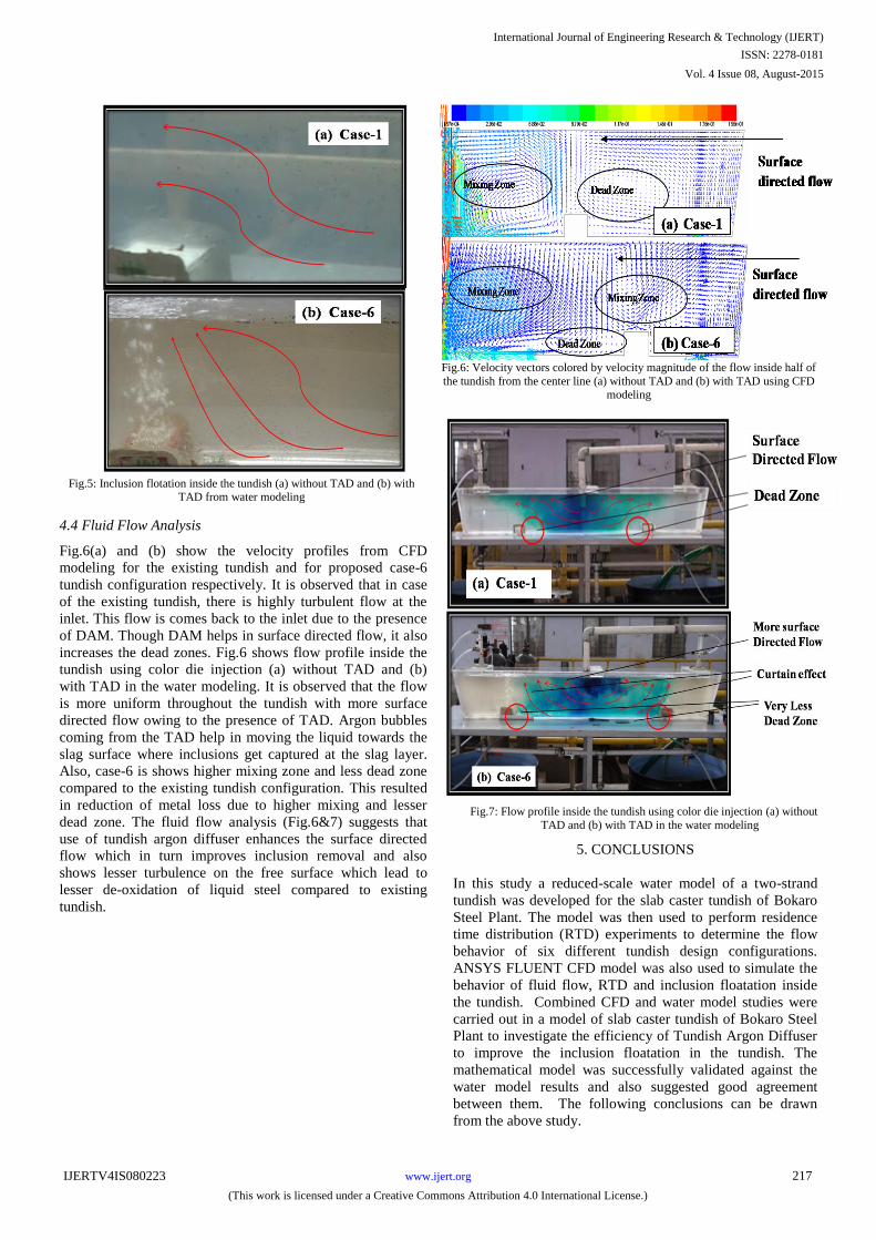
Fig.5: Inclusion flotation inside the tundish (a) without TAD and (b) with
TAD from water modeling
4.4 Fluid Flow Analysis
Fig.6(a) and (b) show the velocity profiles from CFD
modeling for the existing tundish and for proposed case-6
tundish configuration respectively. It is observed that in case
of the existing tundish, there is highly turbulent flow at the
inlet. This flow is comes back to the inlet due to the presence
of DAM. Though DAM helps in surface directed flow, it also
increases the dead zones. Fig.6 shows flow profile inside the
tundish using color die injection (a) without TAD and (b)
with TAD in the water modeling. It is observed that the flow
is more uniform throughout the tundish with more surface
directed flow owing to the presence of TAD. Argon bubbles
coming from the TAD help in moving the liquid towards the
slag surface where inclusions get captured at the slag layer.
Also, case-6 is shows higher mixing zone and less dead zone
compared to the existing tundish configuration. This resulted
in reduction of metal loss due to higher mixing and lesser
dead zone. The fluid flow analysis (Fig.6&7) suggests that
use of tundish argon diffuser enhances the surface directed
flow which in turn improves inclusion removal and also
shows lesser turbulence on the free surface which lead to
lesser de-oxidation of liquid steel compared to existing
tundish.
Fig.6: Velocity vectors colored by velocity magnitude of the flow inside half of
the tundish from the center line (a) without TAD and (b) with TAD using CFD
modeling
Fig.7: Flow profile inside the tundish using color die injection (a) without
TAD
and
(b) with TAD
in the water modeling
5. CONCLUSIONS
In this study a reduced-scale water model of a two-strand
tundish was developed for the slab caster tundish of Bokaro
Steel Plant. The model was then used to perform residence
time distribution (RTD) experiments to determine the flow
behavior of six different tundish design configurations.
ANSYS FLUENT CFD model was also used to simulate the
behavior of fluid flow, RTD and inclusion floatation inside
the tundish. Combined CFD and water model studies were
carried out in a model of slab caster tundish of Bokaro Steel
Plant to investigate the efficiency of Tundish Argon Diffuser
to improve the inclusion floatation in the tundish. The
mathematical model was successfully validated against the
water model results and also suggested good agreement
between them. The following conclusions can be drawn
from the above study.
International Journal of Engineering Research & Technology (IJERT)
ISSN: 2278-0181
www.ijert.orgIJERTV4IS080223
(This work is licensed under a Creative Commons Attribution 4.0 International License.)
Vol. 4 Issue 08, August-2015
217
Tundish argon diffuser enhances the surface directed
flow which in turn improves inclusion removal
compared to the existing tundish.
Use of TAD resulted in reduction metal loss due to
higher mixing and lesser dead zone.
Fluid flow analysis showed lesser turbulence on the free
surface which lead to lesser de-oxidation of liquid steel
after using TAD.
Location of TAD needs to be optimized in order to get
maximum benefit of TAD for improved inclusion
flotation during production of clean steel.
The numerical model was successfully validated against
the water model results. Good agreement was observed
between them.
For BSL conditions, TAD at 2400mm at both sides
from the centre gives best results compared to all other
locations.
ACKNOWLEDGEMENT
The authors are thankful to RDCIS management for
providing valuable support and guidance throughout the
work.
NOMENCLATURES
Cd : Coefficient of discharge
g : Acceleration due to
gravity, m/s2
mi : Mass fraction or concentration
of an injected tracer, i
Gk : Turbulent kinetic
energy
Re : Reynolds number
U : Mean liquid steel velocity
component in i direction (m/s)
Up : Velocity of inclusion
particle, m/s
Vdp : Dispersed plug volume
fraction
Vd : Dead volume fraction
Vm : Mixed volume fraction
Greek symbols
eff : Effective exchange coefficient
for transport of inclusion
: Theoretical Average Residence
Time, s
l : Density of the liquid, kg/m3
dp : Density of the inclusion
particle, kg/m3
g : Density of the gas, kg/m3
: Turbulent kinetic energy, m2/ s2
: Turbulent dissipation rate, m2/s3
µeff : Effective viscosity, N/ms
µl : Liquid viscosity, N/ms
: Surface Tension, N/m2
: Normally distributed
random number
REFERENCES
1.
A. Kumar, D. Mazumdar and S. C. Koria, “Modeling of fluid
Flow and Residence Time Distributions in a four Strand
Tundish for Enhancing Inclusion Floatation”, ISIJ
International, Vol. 48 (2008), No. 1, pp. 38–47
2.
A. Robert, D. Mazumdar, “A Physical and Mathematical
modelling of Flow and Residence Time Distributions (RTD)
in Different Tundish Design” Steel Research Int., 72 (2001),
97-105
3.
Q. Yuan, S. Sivaramakrishnan, S.P. Vanka, B.G. Thomas,
“Computational and Experimental Study of Turbulent
Flow
in a 0.4-Scale Water Model of a Continuous Steel Caster,”
Metal. and Mater. Trans. B, 35 (2004), 967-982
4.
N. Alkishriwi, M. Meinke, W.
Schröder, A. Braun, H.
Pfeifer, “Large-eddy simulations and particle-image
velocimetry measurements of tundish flow”
Steel Research
Int., 77 (2006), 565-575
5.
L. D. Garcia-Demedices, R. Morales, S. Lopez-Ramirez, J.
Barreto-Sandoval,
J. Palafox-Ramos, M. Diaz-Cruz,
“Mathematical Modeling of the Geometry Influence of a
Multiple-Strand Tundish on the Momentum, Heat and Mass
Transfer”,
Steel
Research Int., 72 (2001), 346-353
6.
P. Kovac, J. Kijac, V. Masek, P. Marek, P. Kalmar and K.
Michalek, “Steel Cleanliness Improvement Through Tundish
Configuration optimization, Metalurgija, 2003, No.4, pp. 249-
255.
7.
Ramos-Banderas,
R. D. Morales, J. de. J. Barreto and G.
Solorio-Diaz,
“Modelling Study of Inclusion Removal by
Bubble Flotation
in the Tundish”, Steel
Research
International. Vol. 77
(2006), No. 5, pp. 653-662.
8.
A. Ramos-Banderas, R. D. Morales, L. Garcia-Demedices
and M. Diaz-Cruz,” Mathematical
Simulation and Modeling
of Steel Flow with Gas Bubbling in Through Type Tundish,
ISIJ International, Vol. 43
(2003), No. 5, pp. 524-547.
9.
Zhang, L. and Taniguchi, S.,” Modelling of Inclusion
Removal in a
Tundish by Gas Bubbling”, ISS Transactions,
2001, 28 (9), 55-79.
10.
J. de J. Barreto S., M. A Barron MEZA, and R D Morales,
“Fluid Flow Behaviour in Slab Continuous Casting Tundish
with different Configurations of Gas Bubbling Curtain”,
Ironmaking and Steelmaking, Vol. 35
(2008). No. 6, pp.
44.
11.
Sahai Y, Burval M, “Validity of Reynolds and Froude
similarity criteria for water modeling of melt flow in
tundishes”, Proc. Electric Furnace Conference, ISS-AIME,
Vol. 50, pp.469-474, 1992.
12. Singh S. and Koria S. C.,”Physical Modeling of Steel Flow in
Continuous Casting Tundish”, Ironmaking and Steelmaking,
20(3), 1993, pp 221-230.
International Journal of Engineering Research & Technology (IJERT)
ISSN: 2278-0181
www.ijert.orgIJERTV4IS080223
(This work is licensed under a Creative Commons Attribution 4.0 International License.)
Vol. 4 Issue 08, August-2015
218