rohs reliability impact -...
TRANSCRIPT

LAkre 2007LAkre 2007 11
ROHS Reliability ImpactROHS Reliability ImpactA Reality Check !!!!A Reality Check !!!!
Presented byPresented byLarry AkreLarry Akre
May 17, 2007May 17, 2007©

LAkre 2007LAkre 2007 22
ROHS Reliability ImpactROHS Reliability ImpactRoHS Directive 2002/95/ECRoHS Directive 2002/95/EC•• WEEE Directive 2002/96/ECWEEE Directive 2002/96/EC
Failure MechanismsFailure Mechanisms•• Tin WhiskersTin Whiskers
MechanismsMechanisms•• Solder Joint FailuresSolder Joint Failures•• Mitigation StrategiesMitigation Strategies
Tensile StrengthTensile StrengthSolderabilitySolderability•• TestingTesting•• Shelf LifeShelf Life•• Plating ConsiderationsPlating Considerations
©

LAkre 2007LAkre 2007 33
ROHS Reliability ImpactROHS Reliability ImpactRoHS Directive 2002/95/ECRoHS Directive 2002/95/EC•• WEEE Directive 2002/96/ECWEEE Directive 2002/96/EC
Failure MechanismsFailure Mechanisms•• Tin WhiskersTin Whiskers
MechanismsMechanisms•• Solder Joint FailuresSolder Joint Failures•• Mitigation StrategiesMitigation Strategies
Tensile StrengthTensile StrengthSolderabilitySolderability•• TestingTesting•• Shelf LifeShelf Life•• Plating ConsiderationsPlating Considerations
©

LAkre 2007LAkre 2007 44
RoHS DirectiveRoHS DirectiveThis Directive takes effect on This Directive takes effect on July 1, July 1, 20062006, and with some exceptions (Annex) , and with some exceptions (Annex) totally bans the use of (Article 4.1): totally bans the use of (Article 4.1): •• lead, lead, •• mercury, mercury, •• cadmium, cadmium, •• hexavalent chromium, hexavalent chromium, •• polybrominated biphenyls (PBB's), polybrominated biphenyls (PBB's), •• polybrominated diphenyl ethers (PBDE's), polybrominated diphenyl ethers (PBDE's), •• in electronic and electrical products and in electronic and electrical products and
equipmentequipment
©
LAkre 2007LAkre 2007 55
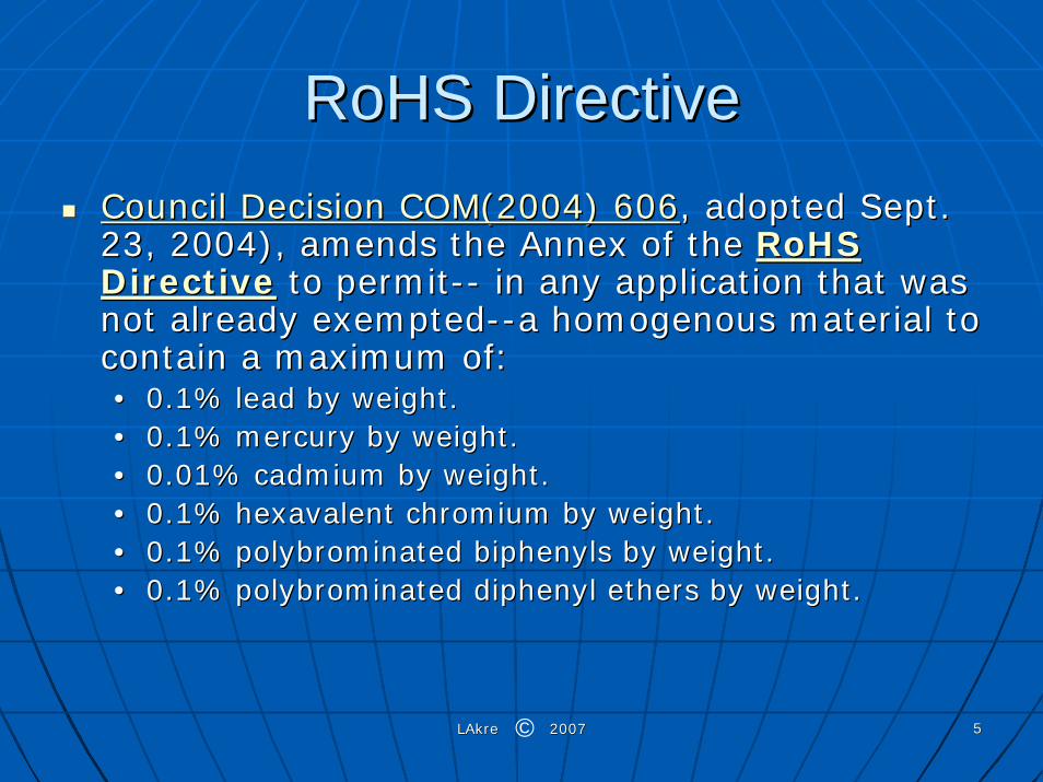
RoHS DirectiveRoHS DirectiveCouncil Decision COM(2004) 606Council Decision COM(2004) 606, adopted Sept. , adopted Sept. 23, 2004), amends the Annex of the 23, 2004), amends the Annex of the RoHS RoHS DirectiveDirective to permitto permit---- in any application that was in any application that was not already exemptednot already exempted----a homogenous material to a homogenous material to contain a maximum of: contain a maximum of: •• 0.1% lead by weight. 0.1% lead by weight. •• 0.1% mercury by weight. 0.1% mercury by weight. •• 0.01% cadmium by weight. 0.01% cadmium by weight. •• 0.1% hexavalent chromium by weight. 0.1% hexavalent chromium by weight. •• 0.1% polybrominated biphenyls by weight. 0.1% polybrominated biphenyls by weight. •• 0.1% polybrominated diphenyl ethers by weight.0.1% polybrominated diphenyl ethers by weight.
©

LAkre 2007LAkre 2007 66
RoHS DirectiveRoHS DirectiveWEEE Directive InfluenceWEEE Directive Influence
Makes the producer (the company whose brand is on the Makes the producer (the company whose brand is on the equipmentequipment---- or the importer/exporter) pay for the collection, or the importer/exporter) pay for the collection, treatment, recovery, and disposal of their equipment (Article 5)treatment, recovery, and disposal of their equipment (Article 5). . For sales to businesses, this cost may be shared between the For sales to businesses, this cost may be shared between the seller and buyer (Article 9, as amended by seller and buyer (Article 9, as amended by Directive Directive 2003/108/EC2003/108/EC). The actual processing may be done by the ). The actual processing may be done by the company itself, or by participating in a producers' compliance company itself, or by participating in a producers' compliance scheme (Article 6.1). scheme (Article 6.1). The producer must provide financial guarantees that they will paThe producer must provide financial guarantees that they will pay y for the handling of their waste equipment, by participating in afor the handling of their waste equipment, by participating in acollective group for this financing, recycling insurance, or a collective group for this financing, recycling insurance, or a blocked bank account (Article 8.2). blocked bank account (Article 8.2). Requires the producer to mark their electrical/ electronic Requires the producer to mark their electrical/ electronic equipment (or the packaging, instructions, and warranty) with thequipment (or the packaging, instructions, and warranty) with the e WEEE Symbol below (Annex IV) after WEEE Symbol below (Annex IV) after August 13, 2005August 13, 2005 (Article (Article 10, paragraph 3).10, paragraph 3).
©

LAkre 2007LAkre 2007 77
RoHS DirectiveRoHS Directive
Most solder materials in lead free Most solder materials in lead free components are many times more components are many times more toxic than the current SnPb toxic than the current SnPb compoundcompoundSoldering and finishing process uses Soldering and finishing process uses so little lead compared to the rest of so little lead compared to the rest of the industry ( < 0.5%)the industry ( < 0.5%)•• Elimination of lead will have no Elimination of lead will have no
significant environmental impact significant environmental impact
©

LAkre 2007LAkre 2007 88
ROHS Reliability ImpactROHS Reliability ImpactRoHS Directive 2002/95/ECRoHS Directive 2002/95/EC•• WEEE Directive 2002/96/ECWEEE Directive 2002/96/EC
Failure MechanismsFailure Mechanisms•• Tin WhiskersTin Whiskers
MechanismsMechanisms•• Solder Joint FailuresSolder Joint Failures•• Mitigation StrategiesMitigation Strategies
Tensile StrengthTensile StrengthSolderabilitySolderability•• TestingTesting•• Shelf LifeShelf Life•• Plating ConsiderationsPlating Considerations
©

LAkre 2007LAkre 2007 99
ROHS Reliability ImpactROHS Reliability ImpactRoHS Directive 2002/95/ECRoHS Directive 2002/95/EC•• WEEE Directive 2002/96/ECWEEE Directive 2002/96/EC
Failure MechanismsFailure Mechanisms•• Tin WhiskersTin Whiskers
MechanismsMechanisms•• Solder Joint FailuresSolder Joint Failures•• Mitigation StrategiesMitigation Strategies
Tensile StrengthTensile StrengthSolderabilitySolderability•• TestingTesting•• Shelf LifeShelf Life•• Plating ConsiderationsPlating Considerations
©

LAkre 2007LAkre 2007 1010
ROHS Reliability ImpactROHS Reliability ImpactRoHS Directive 2002/95/ECRoHS Directive 2002/95/EC•• WEEE Directive 2002/96/ECWEEE Directive 2002/96/EC
Failure MechanismsFailure Mechanisms•• Tin WhiskersTin Whiskers
MechanismsMechanisms•• Solder Joint FailuresSolder Joint Failures•• Mitigation StrategiesMitigation Strategies
Tensile StrengthTensile StrengthSolderabilitySolderability•• TestingTesting•• Shelf LifeShelf Life•• Plating ConsiderationsPlating Considerations
©
LAkre 2007LAkre 2007 1111
Tin WhiskersTin Whiskers
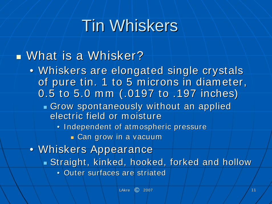
What is a Whisker?What is a Whisker?•• Whiskers are elongated single crystals Whiskers are elongated single crystals
of pure tin. 1 to 5 microns in diameter, of pure tin. 1 to 5 microns in diameter, 0.5 to 5.0 mm (.0197 to .197 inches)0.5 to 5.0 mm (.0197 to .197 inches)
Grow spontaneously without an applied Grow spontaneously without an applied electric field or moistureelectric field or moisture
•• Independent of atmospheric pressureIndependent of atmospheric pressureCan grow in a vacuumCan grow in a vacuum
•• Whiskers AppearanceWhiskers AppearanceStraight, kinked, hooked, forked and hollowStraight, kinked, hooked, forked and hollow
•• Outer surfaces are striatedOuter surfaces are striated
©

LAkre 2007LAkre 2007 1212
ROHS Reliability ImpactROHS Reliability ImpactRoHS Directive 2002/95/ECRoHS Directive 2002/95/EC•• WEEE Directive 2002/96/ECWEEE Directive 2002/96/EC
Failure MechanismsFailure Mechanisms•• Tin WhiskersTin Whiskers
MechanismsMechanisms•• Solder Joint FailuresSolder Joint Failures•• Mitigation StrategiesMitigation Strategies
Tensile StrengthTensile StrengthSolderabilitySolderability•• TestingTesting•• Shelf LifeShelf Life•• Plating ConsiderationsPlating Considerations
©

LAkre 2007LAkre 2007 1313
Tin Whisker MechanismsTin Whisker MechanismsResidual Stresses with the tin platingResidual Stresses with the tin plating•• ContaminatesContaminates
Organic brightenersOrganic brightenerscoppercopper
•• Grain SizeGrain SizeSmall grain size (bright acid tin) 0.5 to .8 um (19.7 to 31.5) Small grain size (bright acid tin) 0.5 to .8 um (19.7 to 31.5) micromicro--inches diameter, 0.2 to 1.0 % carbon contentinches diameter, 0.2 to 1.0 % carbon content
•• Shiny appearance will exhibit high probability to promote whiskeShiny appearance will exhibit high probability to promote whisker r growthgrowth
Large grain size (Matte tin) 1 to 5 um (39.3 to 197) microLarge grain size (Matte tin) 1 to 5 um (39.3 to 197) micro--inches diameter, 0.005 to 0.050 % carbon contentinches diameter, 0.005 to 0.050 % carbon content
•• Dull appearance will exhibit low probability to promote whisker Dull appearance will exhibit low probability to promote whisker growth growth
•• Current densityCurrent densityElectroElectro--deposited finishes are considered at greater risk deposited finishes are considered at greater risk because higher current densities produced higher residual because higher current densities produced higher residual stresses and more whiskersstresses and more whiskers
©

LAkre 2007LAkre 2007 1414
Tin Whisker MechanismsTin Whisker MechanismsDamage to Tin Coating SurfacesDamage to Tin Coating Surfaces•• Bending, stretching, scratching or nicking of the Bending, stretching, scratching or nicking of the
plating creates localized stresses which serve as plating creates localized stresses which serve as the nucleation point for whiskersthe nucleation point for whiskers
Handling damageHandling damage
Mechanical Loading to Tin Coating SurfacesMechanical Loading to Tin Coating Surfaces•• Turning of nuts or screws or spring loaded fixturesTurning of nuts or screws or spring loaded fixtures
©

LAkre 2007LAkre 2007 1515
Tin Whisker MechanismsTin Whisker MechanismsFormation of Intermetallic compoundsFormation of Intermetallic compounds
•• ((CuCu66SnSn55), (), (NiNi33SnSn44)) Eta andEta and ((CuCu33SnSn), (), (NiSnNiSn33)) Epsilon Epsilon phasesphases between the Tin grain boundaries between the Tin grain boundaries
•• Lack of barrier coating between substrate (i.e. Brass) Lack of barrier coating between substrate (i.e. Brass) and Tin Coatingand Tin Coating
Copper Ion MigrationCopper Ion Migration
•• Using Copper barrier coating between substrate (i.e. Using Copper barrier coating between substrate (i.e. Brass) and Tin CoatingBrass) and Tin Coating
Copper Ion MigrationCopper Ion Migration
•• Using Nickel barrier coating between substrate (i.e. Using Nickel barrier coating between substrate (i.e. Brass) and Tin CoatingBrass) and Tin Coating
Nickel Ion Migration Nickel Ion Migration
©

LAkre 2007LAkre 2007 1616
Whisker PhotosWhisker Photos
©

LAkre 2007LAkre 2007 1717
Whisker PhotosWhisker Photos
©

LAkre 2007LAkre 2007 1818
Whisker PhotosWhisker Photos
©

LAkre 2007LAkre 2007 1919
Whisker PhotosWhisker PhotosMatte Tin on Copper substrate subjected to 260°C(500°F) reflow Matte Tin on Copper substrate subjected to 260°C(500°F) reflow
grew tin whiskers in accelerated life tests.grew tin whiskers in accelerated life tests.
©

LAkre 2007LAkre 2007 2020
Whisker PhotosWhisker PhotosMatte tin with a nickel barrier between the copper substrate andMatte tin with a nickel barrier between the copper substrate and
tin, whiskers did not form in accelerated life tests @ 260°C(500tin, whiskers did not form in accelerated life tests @ 260°C(500°F)°F)
©
LAkre 2007LAkre 2007 2121
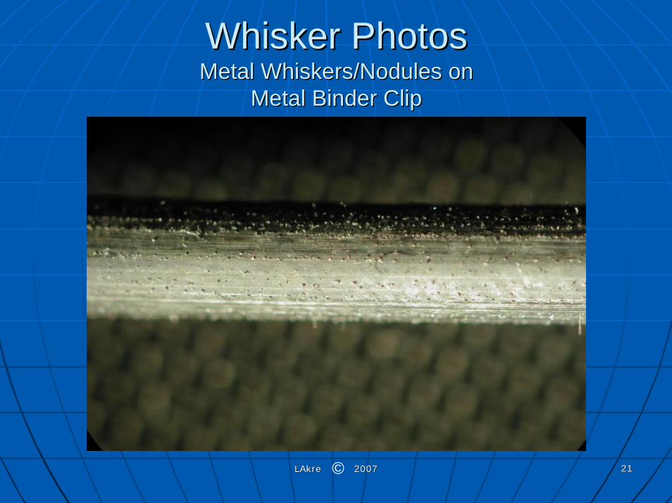
Whisker Photos Whisker Photos Metal Whiskers/Nodules onMetal Whiskers/Nodules on
Metal Binder ClipMetal Binder Clip
©

LAkre 2007LAkre 2007 2222
Whisker Photos Whisker Photos Metal Whiskers/Nodules onMetal Whiskers/Nodules on
Metal Binder ClipMetal Binder Clip
©

LAkre 2007LAkre 2007 2323
Military Failures from Whisker Military Failures from Whisker growthgrowth
Military Airplane:Military Airplane: G. Davy, "G. Davy, "Relay Failure Caused by Tin WhiskersRelay Failure Caused by Tin Whiskers", ", Northrop Grumman Electronic Systems Technical Article, October 2Northrop Grumman Electronic Systems Technical Article, October 2002 002 Patriot Missile:Patriot Missile: Anoplate WWW SiteAnoplate WWW Site:: Suspected tin whisker related Suspected tin whisker related problems (Fall 2000) problems (Fall 2000) Phoenix Air to Air Missile:Phoenix Air to Air Missile: L. Corbid, "Constraints on the Use of Tin L. Corbid, "Constraints on the Use of Tin Plate in Miniature Electronic Circuits", Proceedings 3rd InternaPlate in Miniature Electronic Circuits", Proceedings 3rd International tional SAMPE Electronics Conference, pp. 773SAMPE Electronics Conference, pp. 773--779, June 20779, June 20--22, 1989. 22, 1989. FF--15 Radar:15 Radar: B. Nordwall, "Air Force Links Radar Problems to Growth of B. Nordwall, "Air Force Links Radar Problems to Growth of Tin Whiskers", Aviation Week and Space Technology, June, 20, 198Tin Whiskers", Aviation Week and Space Technology, June, 20, 1986, pp. 6, pp. 6565--70 70 U.S. Missile Program:U.S. Missile Program: J. Richardson, and B. Lasley, "Tin Whisker J. Richardson, and B. Lasley, "Tin Whisker Initiated Vacuum Metal Arcing in Spacecraft Electronics," ProceeInitiated Vacuum Metal Arcing in Spacecraft Electronics," Proceedings dings 1992 Government Microcircuit Applications Conference, Vol. XVIII1992 Government Microcircuit Applications Conference, Vol. XVIII, pp. 119 , pp. 119 -- 122, November 10 122, November 10 -- 12, 1992. 12, 1992. U.S. Missile Program:U.S. Missile Program: K Heutel and R. Vetter, "Problem Notification: Tin K Heutel and R. Vetter, "Problem Notification: Tin Whisker growth in electronic assemblies", Feb. 19, 1988, memoranWhisker growth in electronic assemblies", Feb. 19, 1988, memorandum dum
©

LAkre 2007LAkre 2007 2424
Medical Failures from Whisker Medical Failures from Whisker growthgrowth
Heart Pacemaker RecallHeart Pacemaker Recall Food and Drug Food and Drug Administration March 1986 Administration March 1986 Apnea Monitor FailuresApnea Monitor Failures:: J. Downs, J. Downs, "The Phenomenon of Zinc Whisker Growth "The Phenomenon of Zinc Whisker Growth and the Rotary Switch (or, How the Switch and the Rotary Switch (or, How the Switch Industry Captured the Abominable Industry Captured the Abominable Snowman)", Metal Finishing, August 1994, Snowman)", Metal Finishing, August 1994, pp. 23pp. 23--2525 NOTE:NOTE: This issue is a ZINC This issue is a ZINC Whisker failure!Whisker failure!
©
LAkre 2007LAkre 2007 2525
ROHS Reliability ImpactROHS Reliability ImpactRoHS Directive 2002/95/ECRoHS Directive 2002/95/EC•• WEEE Directive 2002/96/ECWEEE Directive 2002/96/EC
Failure MechanismsFailure Mechanisms•• Tin WhiskersTin Whiskers
MechanismsMechanisms•• Solder Joint FailuresSolder Joint Failures•• Mitigation StrategiesMitigation Strategies
Tensile StrengthTensile StrengthSolderabilitySolderability•• TestingTesting•• Shelf LifeShelf Life•• Plating ConsiderationsPlating Considerations
©

LAkre 2007LAkre 2007 2626
Solder Joint FailuresSolder Joint Failures
©
LAkre 2007LAkre 2007 2727
Solder Joint FailuresSolder Joint Failures
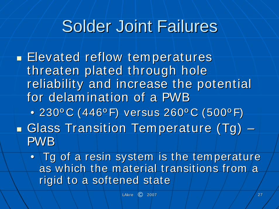
Elevated reflow temperatures Elevated reflow temperatures threaten plated through hole threaten plated through hole reliability and increase the potential reliability and increase the potential for delamination of a PWBfor delamination of a PWB•• 230230ººC (446C (446ººF) versus F) versus 260260ººC (500C (500ººF) F)
Glass Transition Temperature (Tg) Glass Transition Temperature (Tg) ––PWBPWB•• Tg of a resin system is the temperature Tg of a resin system is the temperature
as which the material transitions from a as which the material transitions from a rigid to a softened staterigid to a softened state
©

LAkre 2007LAkre 2007 2828
Solder Joint FailuresSolder Joint Failures
•• --Tg is the material property typically Tg is the material property typically used by Industry for comparing thermal used by Industry for comparing thermal robustnessrobustness
Coefficient of Thermal Expansion Coefficient of Thermal Expansion (CTE)(CTE)•• -- CTE is the measure of a materialCTE is the measure of a material’’s s
expansion both below and above the Tg expansion both below and above the Tg expressed in PPM expressed in PPM
©

LAkre 2007LAkre 2007 2929
Solder Joint FailuresSolder Joint Failures•• -- Below Tg, a PWB material will expand Below Tg, a PWB material will expand
according to its CTEaccording to its CTE•• -- At the Tg, a PWB material will exhibit At the Tg, a PWB material will exhibit
a dramatic increase in its CTEa dramatic increase in its CTELow CTE values for a material at or above Low CTE values for a material at or above its Tg increases the reliability for PTHsits Tg increases the reliability for PTHs
•• Decomposition Temperature Decomposition Temperature –– TdTdThis value is determined by the This value is determined by the measurement of the weight loss of a measurement of the weight loss of a material versus temperaturematerial versus temperature
•• IPC 5 % loss levelIPC 5 % loss level
©
LAkre 2007LAkre 2007 3030
Solder Joint FailuresSolder Joint Failures
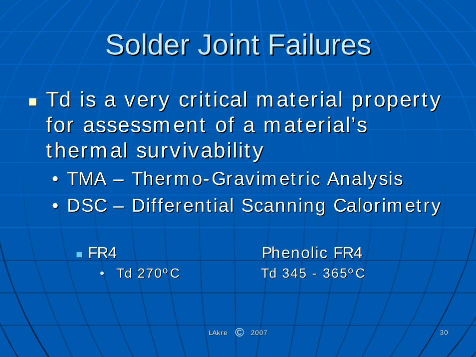
Td is a very critical material property Td is a very critical material property for assessment of a materialfor assessment of a material’’s s thermal survivabilitythermal survivability•• TMA TMA –– ThermoThermo--Gravimetric AnalysisGravimetric Analysis•• DSC DSC –– Differential Scanning CalorimetryDifferential Scanning Calorimetry
FR4 FR4 Phenolic FR4Phenolic FR4•• Td 270Td 270ººCC Td 345 Td 345 -- 365365ººCC
©
LAkre 2007LAkre 2007 3131
Solder Joint FailuresSolder Joint Failures
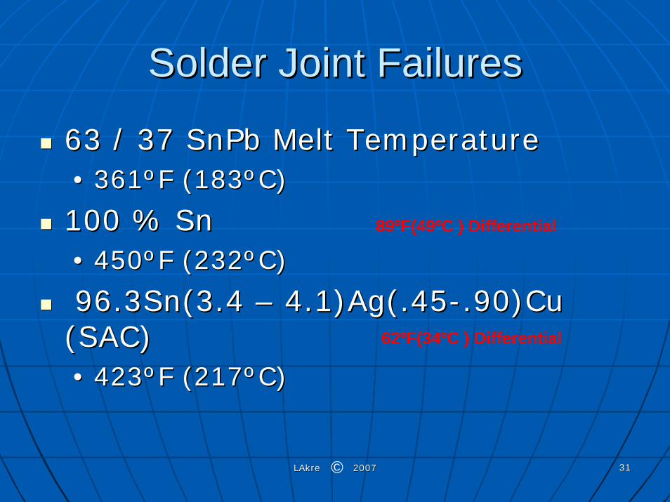
63 / 37 SnPb Melt Temperature63 / 37 SnPb Melt Temperature•• 361361ººF (183F (183ººC)C)
100 % Sn100 % Sn•• 450450ººF F (232(232ººC)C)
96.3Sn(3.4 96.3Sn(3.4 –– 4.1)Ag(.454.1)Ag(.45--.90)Cu .90)Cu (SAC) (SAC) •• 423423ººF F (217(217ººC)C)
89ºF(49ºC ) Differential
62ºF(34ºC ) Differential
©

LAkre 2007LAkre 2007 3232
Solder Joint FailuresSolder Joint Failures
96.3Sn(3.4 96.3Sn(3.4 –– 4.1)Ag(.454.1)Ag(.45--.90)Cu .90)Cu (SAC) MP (SAC) MP 423423ººF F (217(217ººC)C)•• 3030ººC higher surface mount reflow tempC higher surface mount reflow temp•• Slower wetting timeSlower wetting time•• Double the cost for the raw materialDouble the cost for the raw material•• Environmental concerns with AgEnvironmental concerns with Ag•• Stronger and stiffer than SnPb but lower Stronger and stiffer than SnPb but lower
ductilityductility
©

LAkre 2007LAkre 2007 3333
Solder Joint FailuresSolder Joint Failures96.3Sn(3.4 96.3Sn(3.4 –– 4.1)Ag(.454.1)Ag(.45--.90)Cu (SAC) MP .90)Cu (SAC) MP 423423ººF F (217(217ººC)C)•• Large thermal mass of PWBLarge thermal mass of PWB
Large componentLarge component-- coldest spotcoldest spotSmall component Small component –– highest spothighest spot
•• Reflow Soldering temperatures must reach Reflow Soldering temperatures must reach >>260260ººC ( 500C ( 500ººF)F)
Aluminum electrolytic capacitors suffer dielectric Aluminum electrolytic capacitors suffer dielectric cracking at temp cracking at temp >> 245245ººC (473C (473ººF)F)Large plastic grid arrays are prone to warping at Large plastic grid arrays are prone to warping at >>260260ººC ( 500C ( 500ººF)F)Thermal expansion of PWB substrate resulting in Thermal expansion of PWB substrate resulting in weakened or cracked PTHsweakened or cracked PTHs
30ºC (54ºF)ºC (54ºF)
©

LAkre 2007LAkre 2007 3434
Solder Joint FailuresSolder Joint Failures
Lead Free Soldering will increase the Lead Free Soldering will increase the following defectsfollowing defects
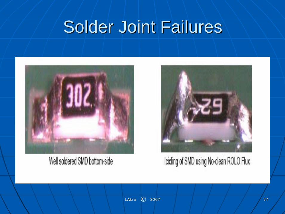
NonNon--WettingWettingInsufficient SolderInsufficient SolderDeDe--WettingWettingIcicle FormationIcicle FormationColder Solder JointsColder Solder JointsGrainy SolderGrainy SolderBlow HolesBlow HolesSolder BallsSolder BallsFillet LiftingFillet LiftingPTH CrackingPTH Cracking
©

LAkre 2007LAkre 2007 3535
Solder Joint FailuresSolder Joint Failures
©
LAkre 2007LAkre 2007 3636
Solder Joint FailuresSolder Joint Failures
©
LAkre 2007LAkre 2007 3737
Solder Joint FailuresSolder Joint Failures
©

LAkre 2007LAkre 2007 3838
Solder Joint FailuresSolder Joint Failures
©

LAkre 2007LAkre 2007 3939
Solder Joint FailuresSolder Joint Failures
©

LAkre 2007LAkre 2007 4040
Solder Joint FailuresSolder Joint Failures
©

LAkre 2007LAkre 2007 4141
Solder Joint FailuresSolder Joint Failures
©

LAkre 2007LAkre 2007 4242
Solder Joint FailuresSolder Joint Failures
©

LAkre 2007LAkre 2007 4343
Solder Joint FailuresSolder Joint Failures
©

LAkre 2007LAkre 2007 4444
ROHS Reliability ImpactROHS Reliability ImpactRoHS Directive 2002/95/ECRoHS Directive 2002/95/EC•• WEEE Directive 2002/96/ECWEEE Directive 2002/96/EC
Failure MechanismsFailure Mechanisms•• Tin WhiskersTin Whiskers•• Solder Joint FailuresSolder Joint Failures
MechanismsMechanisms•• Mitigation StrategiesMitigation Strategies
Tensile StrengthTensile StrengthSolderabilitySolderability•• TestingTesting•• Shelf LifeShelf Life•• Plating ConsiderationsPlating Considerations
©

LAkre 2007LAkre 2007 4545
Tin Whisker Mitigation StrategiesTin Whisker Mitigation StrategiesConformal Coat applied over top of a whiskerConformal Coat applied over top of a whisker--prone surface prone surface
will will NOTNOT prevent the formation of tin whiskersprevent the formation of tin whiskers
Whisker growths INITIATE faster on specimens that are Whisker growths INITIATE faster on specimens that are covered with conformal coatingcovered with conformal coating•• Conformal coating also reduces but does not eliminate) Conformal coating also reduces but does not eliminate)
the rate of growth of tin whiskers compared to an the rate of growth of tin whiskers compared to an uncoated specimen.uncoated specimen.
Annealing Tin coating @ 302º F (150º C)Annealing Tin coating @ 302º F (150º C)•• Initial testing appears to be promisingInitial testing appears to be promising
©

LAkre 2007LAkre 2007 4646
ROHS Reliability ImpactROHS Reliability ImpactRoHS Directive 2002/95/ECRoHS Directive 2002/95/EC•• WEEE Directive 2002/96/ECWEEE Directive 2002/96/EC
Failure MechanismsFailure Mechanisms•• Tin WhiskersTin Whiskers
MechanismsMechanisms•• Solder Joint FailuresSolder Joint Failures•• Mitigation StrategiesMitigation Strategies
Tensile StrengthTensile StrengthSolderabilitySolderability•• TestingTesting•• Shelf LifeShelf Life•• Plating ConsiderationsPlating Considerations
©

LAkre 2007LAkre 2007 4747
Tensile StrengthTensile StrengthThe tensile strength of solder increases depending on tin content. At room temperature the tensile strength reaches its peak at 65% (7,900 psi).
©

LAkre 2007LAkre 2007 4848
Electrical ConductivityElectrical ConductivityThere is a straightforward linear correlation between the tin content and the electrical conductivity of the alloy. the higher the tin content in the alloy, the better the electrical conductivity.
©

LAkre 2007LAkre 2007 4949
Thermal ConductivityThermal ConductivityThe thermal conductivity diagram shows the linear relationship between the tin content and the thermal conduction capabilities of the solder alloy. the capability of the alloy to effectively conduct heat to the PC boards becomes an important parameter in residue-free soldering because of the improved capability of the solder to eliminate excess flux.
©
LAkre 2007LAkre 2007 5050
ROHS Reliability ImpactROHS Reliability ImpactRoHS Directive 2002/95/ECRoHS Directive 2002/95/EC•• WEEE Directive 2002/96/ECWEEE Directive 2002/96/ECFailure MechanismsFailure Mechanisms•• Tin WhiskersTin Whiskers•• Solder Joint FailuresSolder Joint Failures•• Mitigation StrategiesMitigation StrategiesTensile StrengthTensile StrengthSolderabilitySolderability•• TestingTesting•• Shelf LifeShelf Life•• Plating ConsiderationsPlating Considerations
©

LAkre 2007LAkre 2007 5151
Solderability TestingSolderability TestingFormation of Intermetallic compoundsFormation of Intermetallic compounds
CopperCopper((CuCu66SnSn55)) Eta andEta and ((CuCu33SnSn)Epsilon phases)Epsilon phases between the Tin grain between the Tin grain
boundariesboundariesNickelNickel
((NiNi33SnSn44) Eta and () Eta and (NiSnNiSn33)) Epsilon phasesEpsilon phases between the Tin grain between the Tin grain boundariesboundaries
•• Eta Phase promotes solderability with a lower activation Eta Phase promotes solderability with a lower activation energyenergy
•• Epsilon Phase does Epsilon Phase does NotNot promote solderability because of promote solderability because of a high activation energya high activation energy
©

LAkre 2007LAkre 2007 5252
ROHS Reliability ImpactROHS Reliability ImpactRoHS Directive 2002/95/ECRoHS Directive 2002/95/EC•• WEEE Directive 2002/96/ECWEEE Directive 2002/96/EC
Failure MechanismsFailure Mechanisms•• Tin WhiskersTin Whiskers
MechanismsMechanisms•• Solder Joint FailuresSolder Joint Failures•• Mitigation StrategiesMitigation Strategies
Tensile StrengthTensile StrengthSolderabilitySolderability•• TestingTesting•• Shelf LifeShelf Life•• Plating ConsiderationsPlating Considerations
©

LAkre 2007LAkre 2007 5353
Solderability TestingSolderability Testing
IPC/EIA/JEDEC JIPC/EIA/JEDEC J--STDSTD--002B002B•• Coating Durability 3Coating Durability 3
Intended for Sn and SnPb coatingsIntended for Sn and SnPb coatingsSteam agingSteam aging
•• 8 hours +/8 hours +/-- 15 mins15 mins
FluxFlux•• 25% solids white water non activated Rosin25% solids white water non activated Rosin
Kester 145 Kester 145
Solder Bath TemperatureSolder Bath Temperature•• 473 +/473 +/-- 9º F (245 +/9º F (245 +/-- 5º C)5º C)
©

LAkre 2007LAkre 2007 5454
Solderability Plating ConsiderationsSolderability Plating Considerations
SolderabilitySolderability•• Copper migration from base material Copper migration from base material
requires a barrier platingrequires a barrier platingCopper 100 microinchesCopper 100 microinchesNickelNickel 50 microinches 50 microinches
©

LAkre 2007LAkre 2007 5555
ROHS Reliability ImpactROHS Reliability ImpactRoHS Directive 2002/95/ECRoHS Directive 2002/95/EC•• WEEE Directive 2002/96/ECWEEE Directive 2002/96/EC
Failure MechanismsFailure Mechanisms•• Tin WhiskersTin Whiskers
MechanismsMechanisms•• Solder Joint FailuresSolder Joint Failures•• Mitigation StrategiesMitigation Strategies
Tensile StrengthTensile StrengthSolderabilitySolderability•• TestingTesting•• Shelf LifeShelf Life•• Plating ConsiderationsPlating Considerations
©
LAkre 2007LAkre 2007 5656
Solderability Shelf Life Solderability Shelf Life ConsiderationsConsiderations
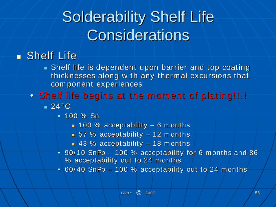
Shelf LifeShelf LifeShelf life is dependent upon barrier and top coating Shelf life is dependent upon barrier and top coating thicknesses along with any thermal excursions that thicknesses along with any thermal excursions that component experiencescomponent experiences
•• Shelf life begins at the moment of plating!!!!Shelf life begins at the moment of plating!!!!24ºC24ºC
•• 100 % Sn 100 % Sn 100 % acceptability 100 % acceptability –– 6 months6 months57 % acceptability 57 % acceptability –– 12 months12 months43 % acceptability 43 % acceptability –– 18 months18 months
•• 90/10 SnPb 90/10 SnPb –– 100 % acceptability for 6 months and 86 100 % acceptability for 6 months and 86 % acceptability out to 24 months% acceptability out to 24 months
•• 60/40 SnPb 60/40 SnPb –– 100 % acceptability out to 24 months100 % acceptability out to 24 months
©
LAkre 2007LAkre 2007 5757
ROHS Reliability ImpactROHS Reliability ImpactRoHS Directive 2002/95/ECRoHS Directive 2002/95/EC•• WEEE Directive 2002/96/ECWEEE Directive 2002/96/EC
Failure MechanismsFailure Mechanisms•• Tin WhiskersTin Whiskers
MechanismsMechanisms•• Solder Joint FailuresSolder Joint Failures•• Mitigation StrategiesMitigation Strategies
Tensile StrengthTensile StrengthSolderabilitySolderability•• TestingTesting•• Shelf LifeShelf Life•• Plating ConsiderationsPlating Considerations
©

LAkre 2007LAkre 2007 5858
Plating ConsiderationsPlating Considerations
Barrier PlatingBarrier Plating•• Nickel per SAE AMSNickel per SAE AMS--QQQQ--NN--290290
2.03um (80 microinches) minimum2.03um (80 microinches) minimum•• Verify via Microsectioning per ASTM B487Verify via Microsectioning per ASTM B487
Top CoatingTop Coating•• Tin Plating per ASTM B545Tin Plating per ASTM B545
(5.08 (5.08 ––7.62 um)200 7.62 um)200 –– 300 microinches300 microinches•• Verify via Microsectioning per ASTM B487Verify via Microsectioning per ASTM B487
©
LAkre 2007LAkre 2007 5959
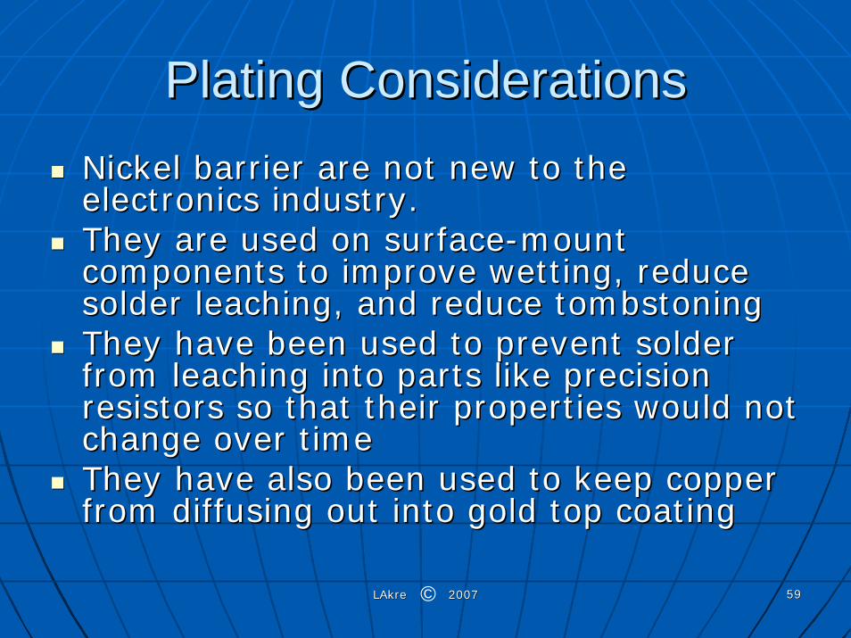
Plating ConsiderationsPlating ConsiderationsNickel barrier are not new to the Nickel barrier are not new to the electronics industry. electronics industry. They are used on surfaceThey are used on surface--mount mount components to improve wetting, reduce components to improve wetting, reduce solder leaching, and reduce tombstoning solder leaching, and reduce tombstoning They have been used to prevent solder They have been used to prevent solder from leaching into parts like precision from leaching into parts like precision resistors so that their properties would not resistors so that their properties would not change over timechange over timeThey have also been used to keep copper They have also been used to keep copper from diffusing out into gold top coatingfrom diffusing out into gold top coating
©

LAkre 2007LAkre 2007 6060
Plating ConsiderationsPlating Considerations
Nickel SulfamateNickel Sulfamate•• Low stress depositLow stress deposit•• Hull Cell AnalysisHull Cell Analysis
ContaminatesContaminates•• LeadLead•• ChromiumChromium•• ZincZinc
Carbon TreatmentCarbon Treatment
©

LAkre 2007LAkre 2007 6161
Plating ConsiderationsPlating Considerations
TinTin•• Hull Cell AnalysisHull Cell Analysis
ContaminatesContaminates•• LeadLead•• ChromiumChromium•• ZincZinc
Carbon TreatmentCarbon Treatment•• Copper contamination critical to Tin WhiskeringCopper contamination critical to Tin Whiskering
©

LAkre 2007LAkre 2007 6262
Plating ConsiderationsPlating Considerations
Barrier PlatingBarrier Plating•• Nickel per SAE AMSNickel per SAE AMS--QQQQ--NN--290290
2.03um (80 microinches) minimum2.03um (80 microinches) minimum•• Verify via Microsectioning per ASTM B487Verify via Microsectioning per ASTM B487
Top CoatingTop Coating•• Palladium Plating per ASTM B679Palladium Plating per ASTM B679
1.27 um(50 microinches) minimum1.27 um(50 microinches) minimum•• Verify via Microsectioning per ASTM B487Verify via Microsectioning per ASTM B487
©
LAkre 2007LAkre 2007 6363
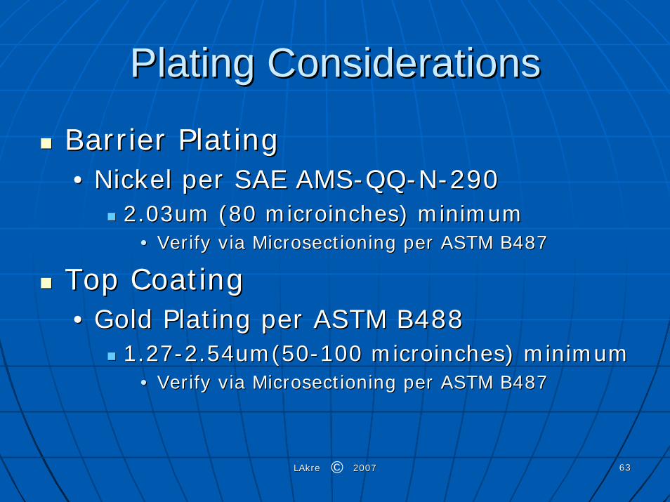
Plating ConsiderationsPlating Considerations
Barrier PlatingBarrier Plating•• Nickel per SAE AMSNickel per SAE AMS--QQQQ--NN--290290
2.03um (80 microinches) minimum2.03um (80 microinches) minimum•• Verify via Microsectioning per ASTM B487Verify via Microsectioning per ASTM B487
Top CoatingTop Coating•• Gold Plating per ASTM B488Gold Plating per ASTM B488
1.271.27--2.54um(502.54um(50--100 microinches) minimum100 microinches) minimum•• Verify via Microsectioning per ASTM B487Verify via Microsectioning per ASTM B487
©

LAkre 2007LAkre 2007 6464
Whisker TestingWhisker Testing
JEDEC Standard JESD22A121JEDEC Standard JESD22A121•• Test Method for Measuring Whisker Test Method for Measuring Whisker
Growth on Tin and Tin Alloy Surface Growth on Tin and Tin Alloy Surface finishesfinishes
Ambient Storage (30ºC, 60% R/H) 3000 Ambient Storage (30ºC, 60% R/H) 3000 cyclescyclesTemperature Cycling (Temperature Cycling (--55 to +85ºC) 3000 55 to +85ºC) 3000 cyclescyclesTemperature Humidity Storage (60ºC, 93% Temperature Humidity Storage (60ºC, 93% R/H) 3000 cyclesR/H) 3000 cycles
©

LAkre 2007LAkre 2007 6565
Whisker TestingWhisker TestingJEDEC Class CriteriaJEDEC Class Criteria
©

LAkre 2007LAkre 2007 6666
Whisker TestingWhisker TestingJEDEC Acceptance CriteriaJEDEC Acceptance Criteria
©