rod tops by time machines unlimitedrodtops.com/pdf/rod_tops_owners_manual.pdfrod tops by time...
TRANSCRIPT

Rod Topsby
Time Machines Unlimited9058 Atwood Rd. Charlevoix, MI 49720
`32 Ford Roadster Convertible Top System Installation and Operation
Manual

Contents
• Introduction Section 1
• Component List Section 2
• Pre-installation Checks Section 3
• Installation Procedures Section 4
• Top System Operation Section 5
• Optional Zip-Out Window Section 6
• Top Maintenance Section 7
• Warrantee Section 8

IntroductionThank you for purchasing a Rod Top system. Rod Tops offers the Hot Rod enthusiast a convertible top system that was engineered using experienced automotive design knowledge. Our engineering approach is to provide a high quality assembly, drawing on a wide range of proven design solutions that result in a cost effective solution for low volume body applications. While it is very important that a top be functional, it must also be ascetically pleasing. All of the Rod Tops built by Time Machines Unlimited are designed to enhance the look of the vehicle while providing protection from the elements.
Our goal is to provide you with a top that adds to the usefulness and enjoyment of your vehicle for many years.
Sincerely,
Dave Draper,
President
Section 1

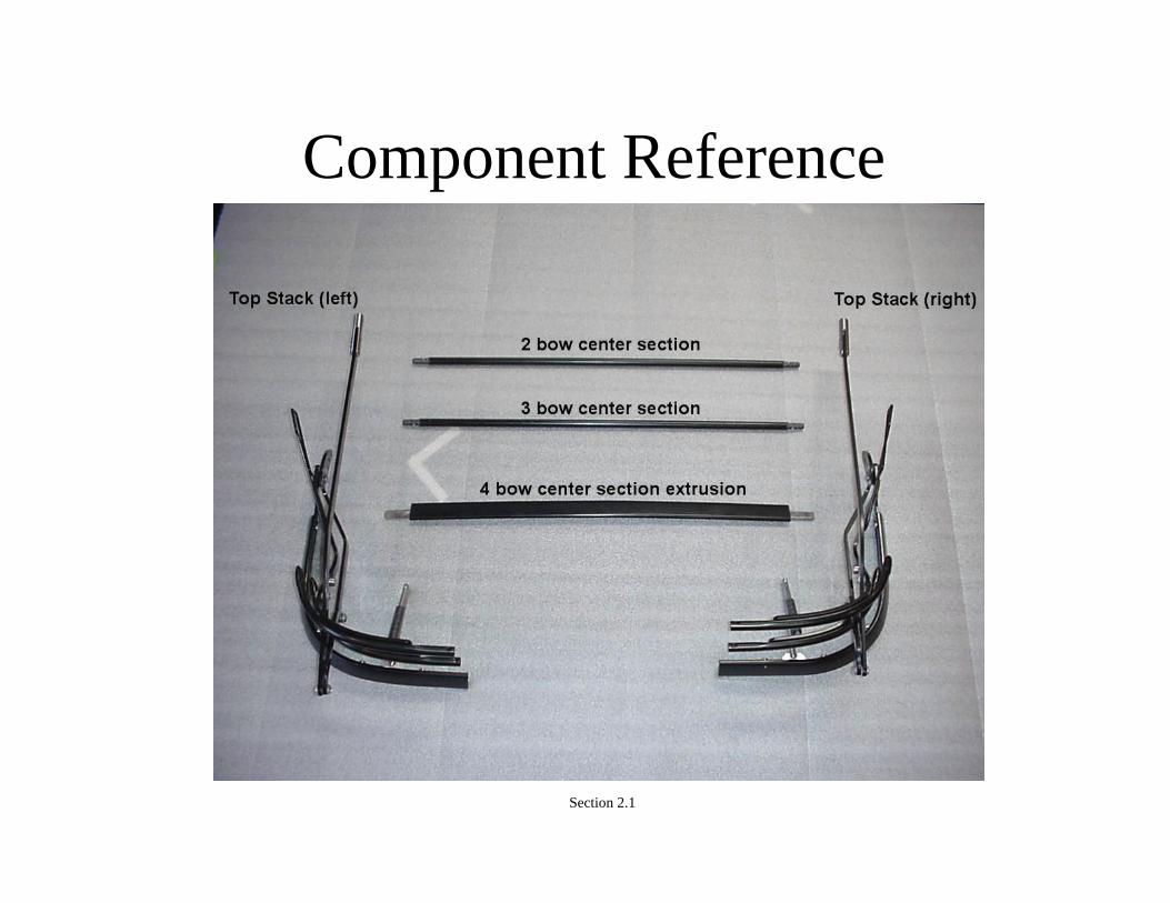
Component List1. Top Stack (left half/right half)
2. 2 and 3 Bow Tubular Center Sections (2)
3. Belt Line Bow Extruded Center Section
4. Header Bracket Assembly
5. Storage Bag
6. Header
7. Top Canvas
8. Top Seals and Trim Accessories
9. Adjusting and Installation Tool
Section 2
Component Reference
Section 2.1

Component Reference
Section 2.2

Component Reference
Section 2.3

Component Reference
Section 2.4

Pre-Installation ChecksTo insure proper alignment between the top system and the body of the
car, several critical measurements must be taken. These measurements will establish the distance between the top of the windshield and the “B” pillar or the lock pillar at the leading edge of the quarter panel (see image on next page). If the distance from the top edge of the windshield (D) is NOT the same on both sides of the car, adjustments to the windshield will have to be made, if possible.
The top is designed to allow for minor adjustments at the header clevis. This adjustment should be used to correct for minor differences in distance that cannot be completed at the windshield. This adjustment will be covered in the installation portion of the manual, Section 4.
For vehicles without a windshield installed, proceed to the installation section of this manual. The Rod Top and the windshield will be used as mounting guides for each other.
It is NOT recommended that the top installation be completed with the body off of the chassis. The measurements required to locate the top properly may change greatly with the body off the chassis.
Section 3
Pre-Installation Checks
Section 3.1
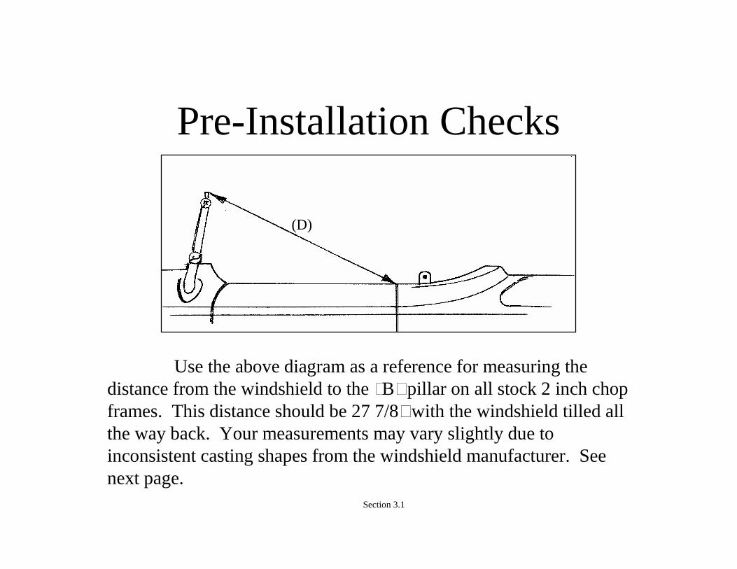
Use the above diagram as a reference for measuring the distance from the windshield to the “B” pillar on all stock 2 inch chop frames. This distance should be 27 7/8” with the windshield tilled all the way back. Your measurements may vary slightly due to inconsistent casting shapes from the windshield manufacturer. See next page.
(D)

Pre-Installation Checks
• The above photo shows both windshield posts in relation to the frame. Note the difference in angle between the two sides, this difference changed the measurement from one side of the car to the other almost 1/8”. Record any difference in your windshield, we will adjust for this in a later step.
Section 3.2
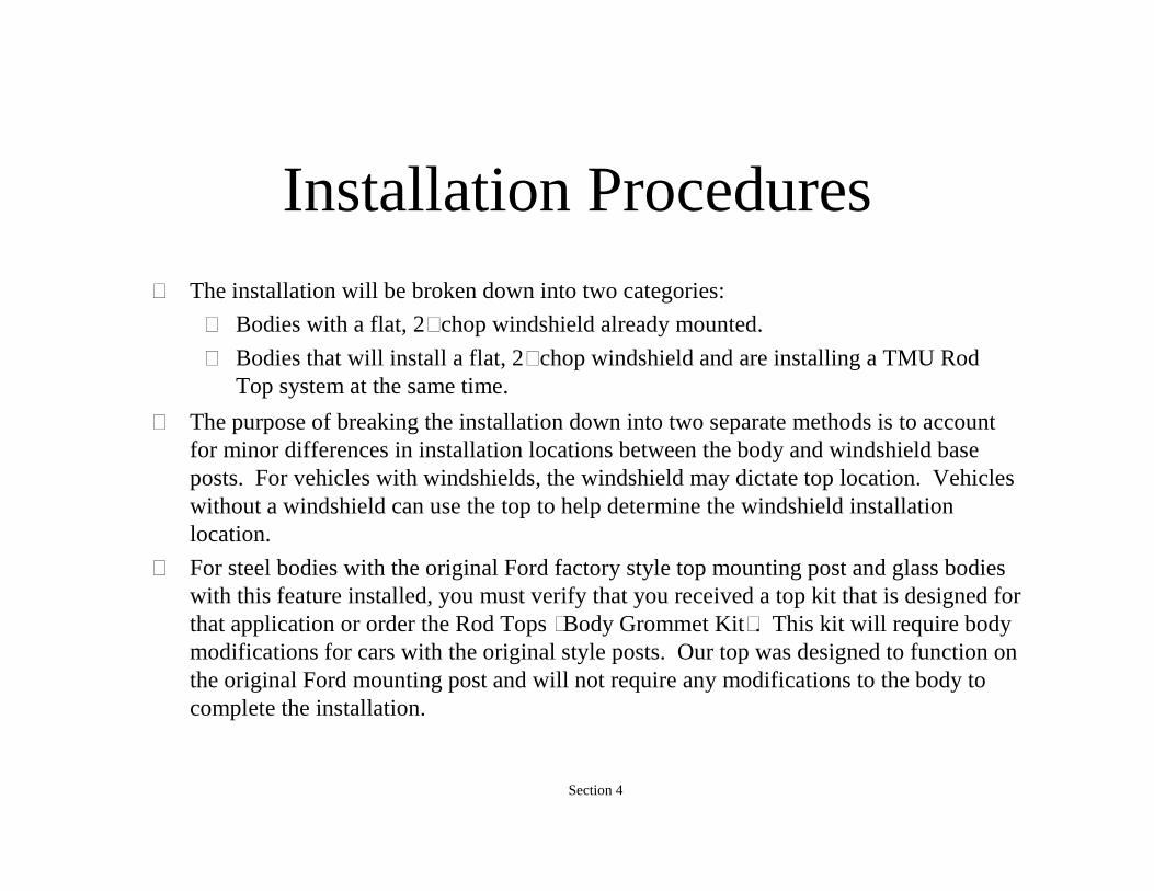
Installation Procedures• The installation will be broken down into two categories:
– Bodies with a flat, 2” chop windshield already mounted.
– Bodies that will install a flat, 2” chop windshield and are installing a TMU Rod Top system at the same time.
Section 4
• The purpose of breaking the installation down into two separate methods is to account for minor differences in installation locations between the body and windshield base posts. For vehicles with windshields, the windshield may dictate top location. Vehicles without a windshield can use the top to help determine the windshield installation location.
• For steel bodies with the original Ford factory style top mounting post and glass bodies with this feature installed, you must verify that you received a top kit that is designed for that application or order the Rod Tops “Body Grommet Kit”. This kit will require body modifications for cars with the original style posts. Our top was designed to function on the original Ford mounting post and will not require any modifications to the body to complete the installation.

Installation Procedures• Vehicles with 2” chop windshield already installed:
For vehicles with the original style top mounting posts, see Section 5.5 and ignore sections 4.1 through 4.7
Start by locating the body mount installation kit. The Body mount kit is not supplied in the standard kit and must be ordered with the top to complete the installation on a body without mounting flags. Optional kit pictured below.
Section 4.1
For installations on finished vehicles, it is recommended that the mounting area be protected with tape.
Measure 3 1/4 inches back from the edge of the door opening and half an inch out from the inside edge of the belt line. This will be the center of the hole for the body grommet. (See figure, next page)
The measurements are true for vehicles that have been stretched from the original ‘32 Ford body dimensions. If your vehicle was manufactured with stretched doors, you must order a special stretched body top kit. If you ordered a Rod Top and did not indicate that the body has been stretched at the time of order, the top will NOT fit properly.
Section 4.2
Installation Procedures

Installation Procedures
Drill a half inch hole at the intersection of the two lines.
Section 4.3
RH side view 3 ¼” Back
RH top view ½” from inside edge

Installation Procedures
The area surrounding the body grommet should be reinforced on the backside using the aluminum block supplied in the body mountkit. The end of the body mount is threaded to offer additional options for securing the grommet once the area is reinforced. The grommet may also be welded to an existing frame structure. See photo next page.
Section 4.4
Installation Procedures
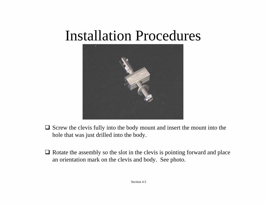
Screw the clevis fully into the body mount and insert the mount into the hole that was just drilled into the body.
Rotate the assembly so the slot in the clevis is pointing forward and place an orientation mark on the clevis and body. See photo.
Section 4.5

Installation Procedure
Using a marker, make two realignment marks at the intersection of the body mount and the vehicle. Each clevis is now side specific and should be identified by the black or white washer at the bottom.
Permanently attach the body mounts using the mounting block. The block should be bedded in a small layer of filler material. Use lubricant on the threads to ease installation of the nut. Pay special attention to the alignment marks. Install the body clevis checking for proper orientation between the vehicle and the clevis slot. Adjust as needed. Installer may use the set screw in the mounting block, the nylon lock nut or both to secure the top mount. See photo next page.
Section 4.6
Installation Procedures
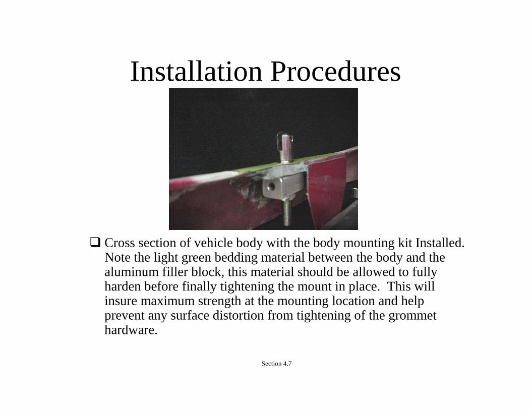
Cross section of vehicle body with the body mounting kit Installed. Note the light green bedding material between the body and the aluminum filler block, this material should be allowed to fully harden before finally tightening the mount in place. This will insure maximum strength at the mounting location and help prevent any surface distortion from tightening of the grommet hardware.
Section 4.7

Installation Procedures Locate the passenger side header bracket assembly.
Remove the A-Rail clevis from the header bracket by removing the quick pin and sliding the clevis off the receiver. Place the clevis and quick pin back in the package.
Section 4.8

Installation Procedures Install the passenger side header bracket assembly on the
windshield post and tighten the allen head set screw with the wrench provided in the kit.
Repeat the header bracket installation process for the drivers’ side of the vehicle.
Section 4.9
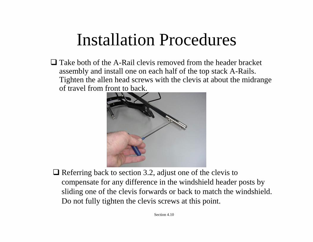
Installation Procedures Take both of the A-Rail clevis removed from the header bracket
assembly and install one on each half of the top stack A-Rails. Tighten the allen head screws with the clevis at about the midrange of travel from front to back.
Referring back to section 3.2, adjust one of the clevis to compensate for any difference in the windshield header posts by sliding one of the clevis forwards or back to match the windshield. Do not fully tighten the clevis screws at this point.
Section 4.10
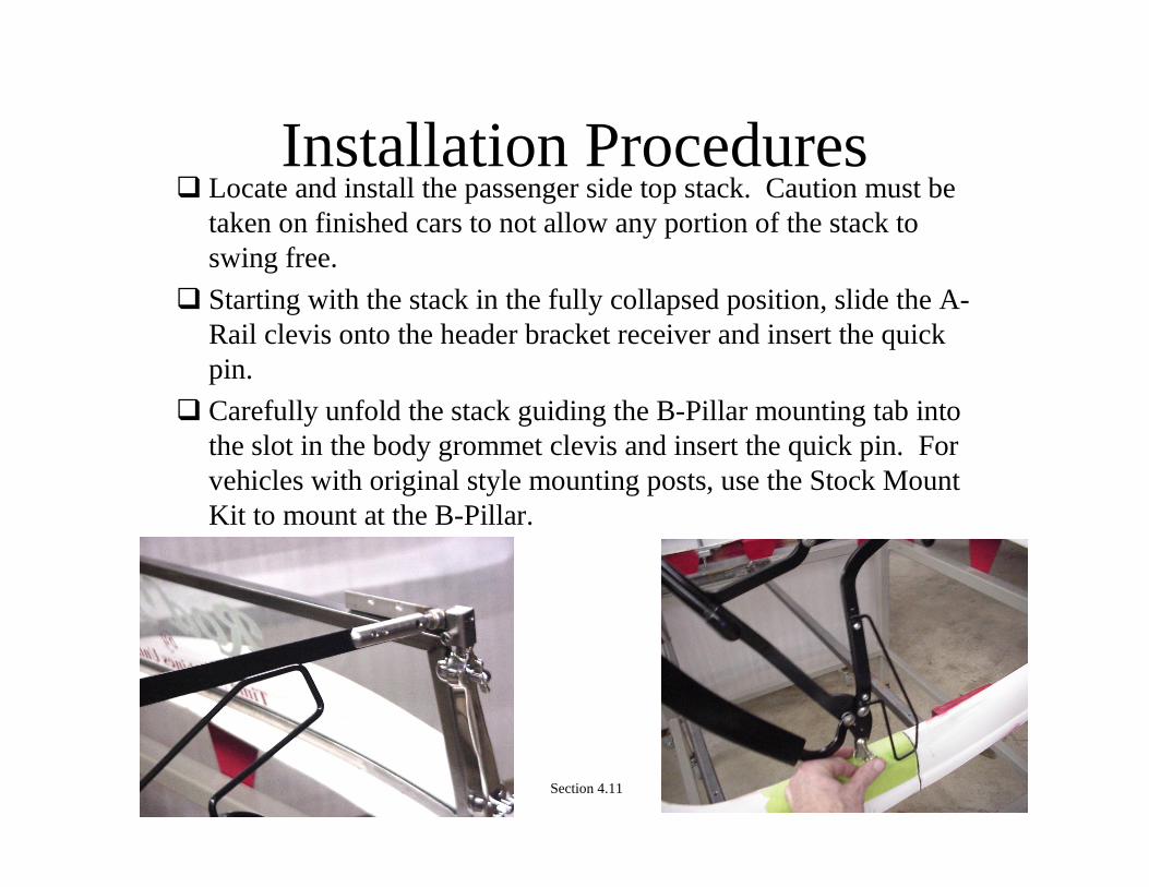
Installation Procedures Locate and install the passenger side top stack. Caution must be
taken on finished cars to not allow any portion of the stack to swing free.
Starting with the stack in the fully collapsed position, slide the A-Rail clevis onto the header bracket receiver and insert the quick pin.
Carefully unfold the stack guiding the B-Pillar mounting tab into the slot in the body grommet clevis and insert the quick pin. For vehicles with original style mounting posts, use the Stock MountKit to mount at the B-Pillar.
Section 4.11
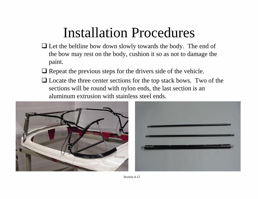
Installation Procedures Let the beltline bow down slowly towards the body. The end of
the bow may rest on the body, cushion it so as not to damage thepaint.
Repeat the previous steps for the drivers side of the vehicle.
Locate the three center sections for the top stack bows. Two of the sections will be round with nylon ends, the last section is an aluminum extrusion with stainless steel ends.
Section 4.12

Installation Procedures Starting with the aluminum section, insert one end into the channel
in the beltline bows section that is on the top stack.
Rotate both beltline bow to about half way up and insert the remaining end into the channel on the other top stack half. Raising the beltline bows to the half way up position allows the tabs toslide into the channels more easily.
Section 4.13
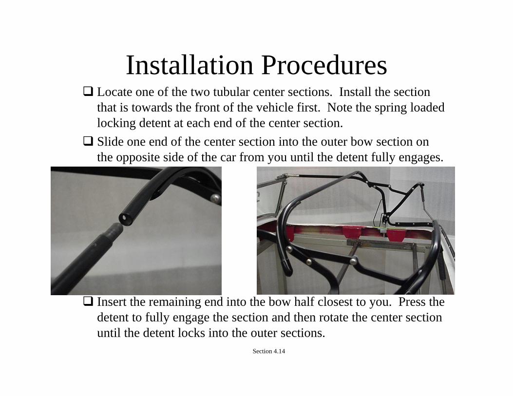
Installation Procedures Locate one of the two tubular center sections. Install the section
that is towards the front of the vehicle first. Note the spring loaded locking detent at each end of the center section.
Slide one end of the center section into the outer bow section on the opposite side of the car from you until the detent fully engages.
Insert the remaining end into the bow half closest to you. Press the detent to fully engage the section and then rotate the center section until the detent locks into the outer sections.
Section 4.14

Installation Procedures
Repeat the process for the second or middle bow center section.
Check all detents to insure they are fully engaged.
Section 4.15
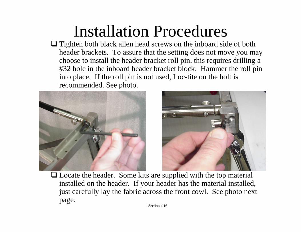
Installation Procedures Tighten both black allen head screws on the inboard side of both
header brackets. To assure that the setting does not move you may choose to install the header bracket roll pin, this requires drilling a #32 hole in the inboard header bracket block. Hammer the roll pin into place. If the roll pin is not used, Loc-tite on the bolt is recommended. See photo.
Locate the header. Some kits are supplied with the top materialinstalled on the header. If your header has the material installed, just carefully lay the fabric across the front cowl. See photo next page.
Section 4.16

Installation Procedures
Place the header over the windshield frame.
Press one of the two header brackets firmly against the header and mark one of the holes for drilling. Make sure the header is fully down on the bracket when marking.
Remove the header from the windshield and drill an 1/8” hole in the spot that was just marked.
Section 4.17
Installation Procedures
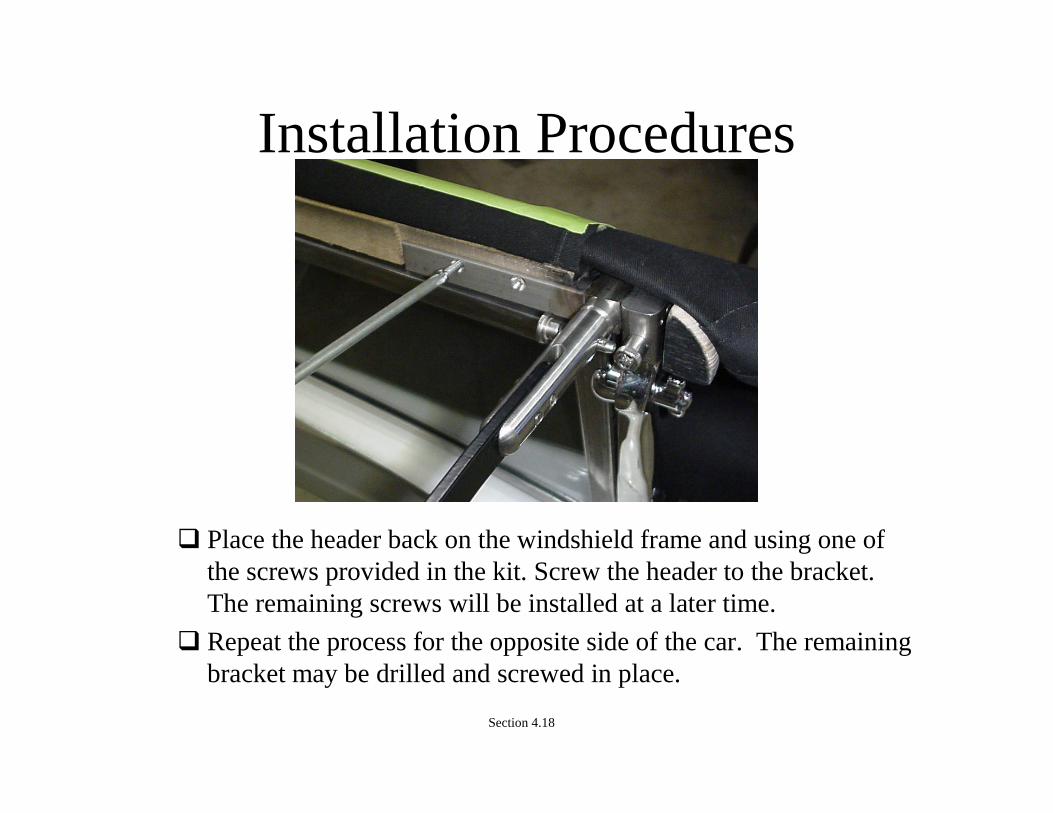
Place the header back on the windshield frame and using one of the screws provided in the kit. Screw the header to the bracket.The remaining screws will be installed at a later time.
Repeat the process for the opposite side of the car. The remaining bracket may be drilled and screwed in place.
Section 4.18

Installation Procedures
Place some form of padding under the beltline bow. A towel or afew rags will work well. This will prevent the top stack from contacting the body while the header is off the car. Normally the header is the last piece removed.
Loosen the allen head screws locking the header to the windshield posts.
Pull the quick release pins from both A-Rail clevis. Slide the header assembly out of both clevis. See next page.
Section 4.19

Installation Procedures
You can now take the header way from the car to drill and screw all remaining holes in the header brackets.
Place the header back on the vehicle reversing the previous steps.
Section 4.20

Installation Procedures It is now time to start the final adjustment to the top stack. The first step is to make sure the bow sections are parallel to the
header and windshield. Looking from the back of the car, compare the relationship between the header and the three bow. If they are not parallel you will have to make an adjustment at one of the A-Rail clevis.
Choose the side that needs to come up slightly and loosen the two screws in the clevis. Sliding the rail farther into the clevis will raise that side of the three bow. Adjust the rail and recheck. Repeat as needed.
Section 4.21
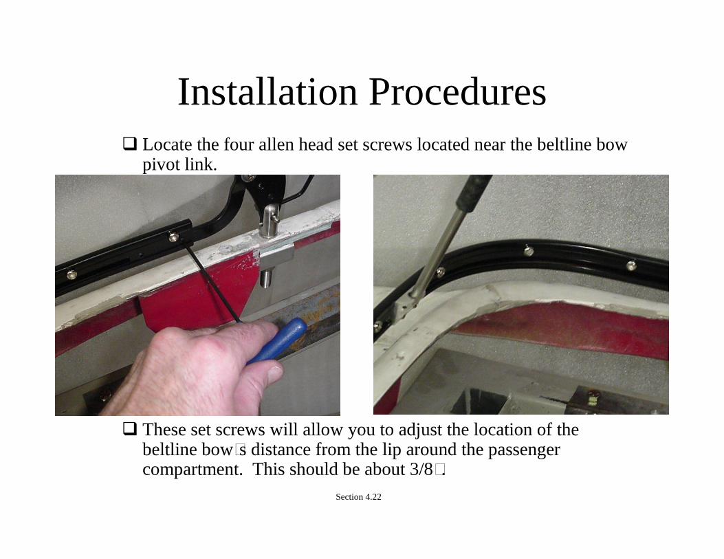
Installation Procedures Locate the four allen head set screws located near the beltline bow
pivot link.
These set screws will allow you to adjust the location of the beltline bow’s distance from the lip around the passenger compartment. This should be about 3/8”.
Section 4.22

Installation Procedures The last adjustment are the link locks. The link locks extend from
the three bow to the beltline bow. The link locks set the height of the beltline bow above the body. The bow should float about 3/8” above and away from the body so the soft bulb seal on the top canvas just touches the body. If there is too much pressure on the paint, dirt on the soft bulb seal can rub through the paint.
Section 4.23
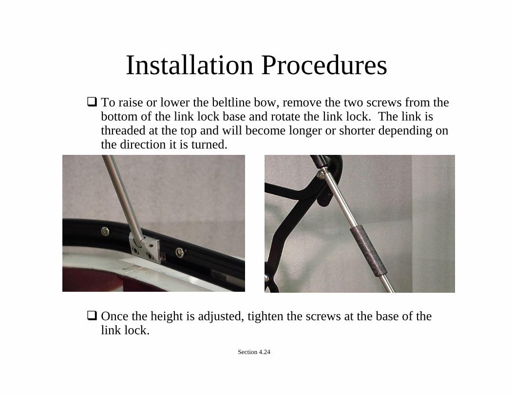
Installation Procedures To raise or lower the beltline bow, remove the two screws from the
bottom of the link lock base and rotate the link lock. The link is threaded at the top and will become longer or shorter depending on the direction it is turned.
Section 4.24
Once the height is adjusted, tighten the screws at the base of the link lock.

Installation ProceduresThe installation of the canvas will vary greatly by body
manufacturer.
All tops will have to complete all the installation steps or have the canvas installed at a local trim shop.
Starting at the header, find and mark the centerline of the header.
Section 4.25

Installation Procedures Glue the header cover to the top of the header. Over lap the fabric
on the header by about an inch. General purpose trim glue will work well for this application.
Section 4.26

Installation Procedures Roll the canvas out over the top stack.
Snap the canvas to the inside of the beltline bow.
Section 4.27

Installation Procedures Located on the inside edges of the canvas are two small pockets.
These pockets are located just ahead of the body clevis mountinglocation.
The pockets will hold the flags located on the top stack and will help tension the top side to side. Hook each flag in a pocket.
Section 4.28

Installation Procedures Lock the link locks by pushing towards the back of the car and
sliding down on the link lock locking sleeve. At the front of the canvas locate the center of canvas mark and
align it with the center of header mark.
With the canvas centered on the header, pull towards the front of the vehicle and down. When the canvas is tight, using 1/4-3/8” steel staples, staple the canvas to the header at the center mark about 3/8” up from the bottom edge of the header. See photo.
Section 4.29

Installation Procedures
Moving to the seam at either side of the top, tension the canvas as before being sure to pull slightly outwards. Staple at seam to header.
Repeat for opposite side.
Section 4.30
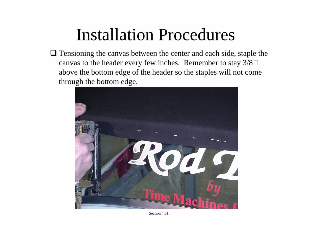
Installation Procedures Tensioning the canvas between the center and each side, staple the
canvas to the header every few inches. Remember to stay 3/8” above the bottom edge of the header so the staples will not comethrough the bottom edge.
Section 4.31
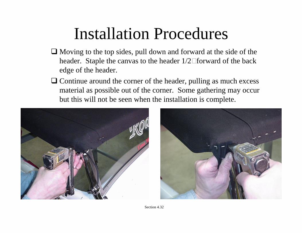
Installation Procedures Moving to the top sides, pull down and forward at the side of the
header. Staple the canvas to the header 1/2” forward of the back edge of the header.
Continue around the corner of the header, pulling as much excessmaterial as possible out of the corner. Some gathering may occur but this will not be seen when the installation is complete.
Section 4.32

Installation Procedures With the canvas fully stapled, using a grease pencil or chalk mark
the location of the edge of the header behind the canvas. Note white line on canvas in photo.
Using scissors, back cut the binding to the point that the header and top edge of the binding meet.
Section 4.33

Installation Procedures Trim the canvas at the header so the canvas is just above the
bottom edge of the header. If the edge of the canvas hangs below the header, it will be visible when the top is complete.
Section 4.34

Installation Procedures Pull the top binding up on the header and staple in several
locations. It is important to be aware of how the binding is pulled and the affect it has on the sides of the top.
Trim any excess binding off as close to the last staple as possible.
Section 4.35
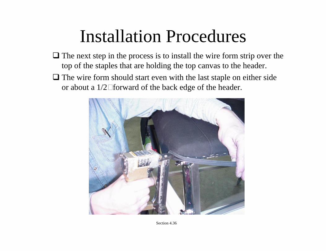
Installation Procedures The next step in the process is to install the wire form strip over the
top of the staples that are holding the top canvas to the header.
The wire form should start even with the last staple on either side or about a 1/2” forward of the back edge of the header.
Section 4.36

Installation Procedures Continue to staple the wire form along the front edge of the header
paying special attention to the bottom edge of the header. The wire form bottom edge should be even with the edge of the header.
Trim the wire form even with the last staple on the opposite side.
Section 4.37

Installation Procedures Locate the small package containing the wire form end cap covers.
Place the end cap over the ends of the wire form and mark the hole location for drilling. The location of the end caps are not critical and are decorative covers for the raw ends of the wire form.
Drill a 3/32” hole at the desired location and install the end caps with the supplied stainless steel screws.
Section 4.38

Installation Procedures Release the link locks and un-tension the top.
Release all the snaps holding the canvas to the beltline bow.
Place a pad under the beltline bow to protect the body and then remove the header and canvas assembly.
Locate the windshield flap.
Working with the header in the bottom side up position, use trimglue to glue the header cover in position over the header and mounting brackets. Apply glue to both surfaces.
Section 4.39

Installation Procedures With the cover glued in place and dry. Place the windshield flap in
place. Note that the windshield flap has two different edges, arolled edge and a double raw edge. The raw edge will go againstthe header.
Staple the flap in place on the header. The staples will also hold the header cover to the header.
Section 4.40

Installation Procedures With the windshield flap in place it is now time to install the foam
seal.
Using masking tape to protect any areas that do not need glue, spread glue on the header cover across the width of the header.
Section 4.41
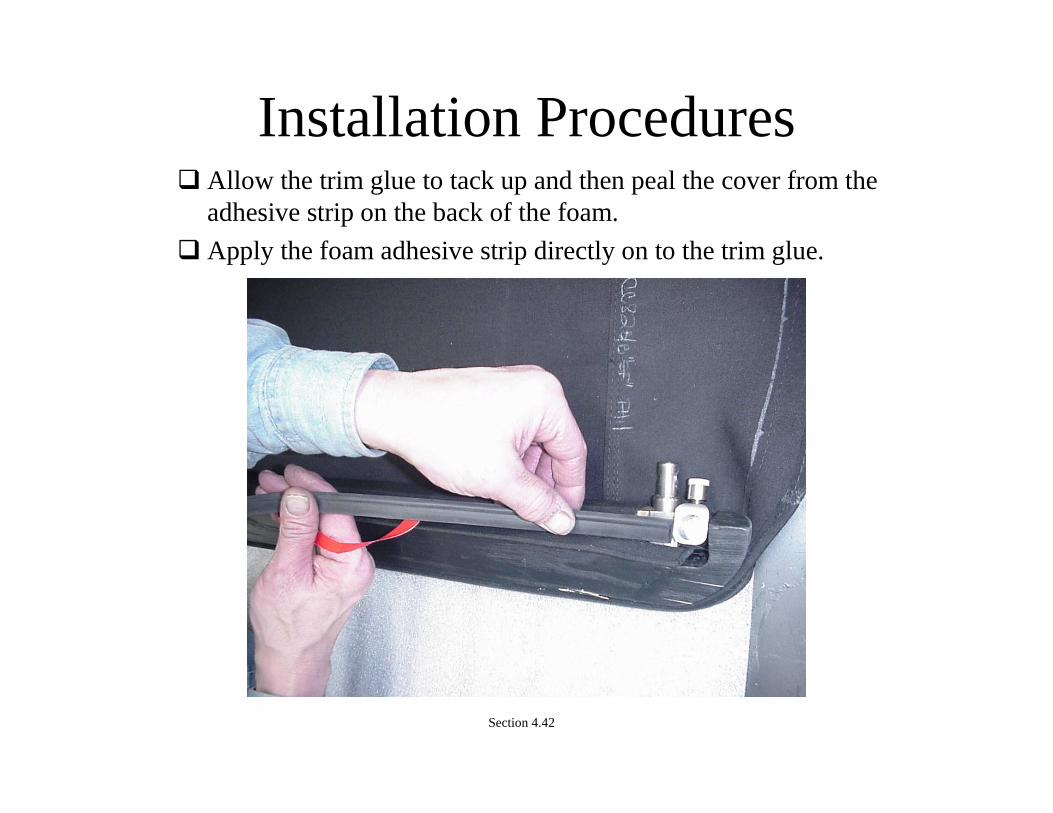
Installation Procedures Allow the trim glue to tack up and then peal the cover from the
adhesive strip on the back of the foam.
Apply the foam adhesive strip directly on to the trim glue.
Section 4.42
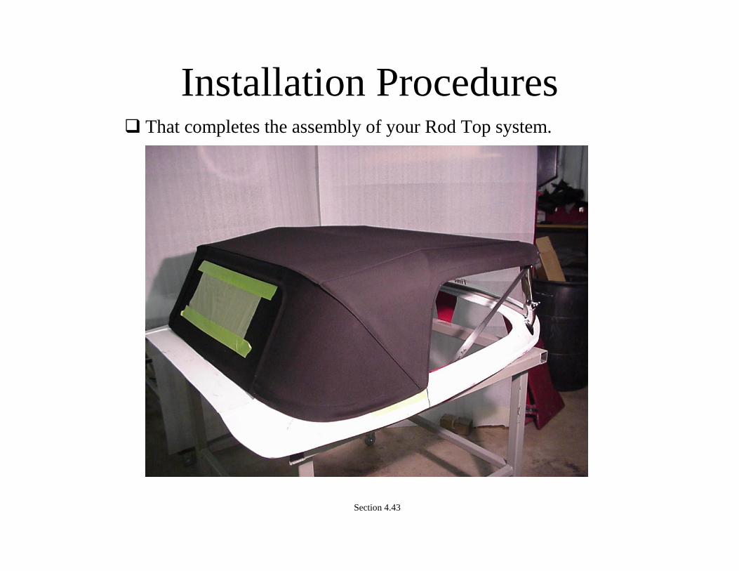
Installation Procedures That completes the assembly of your Rod Top system.
Section 4.43
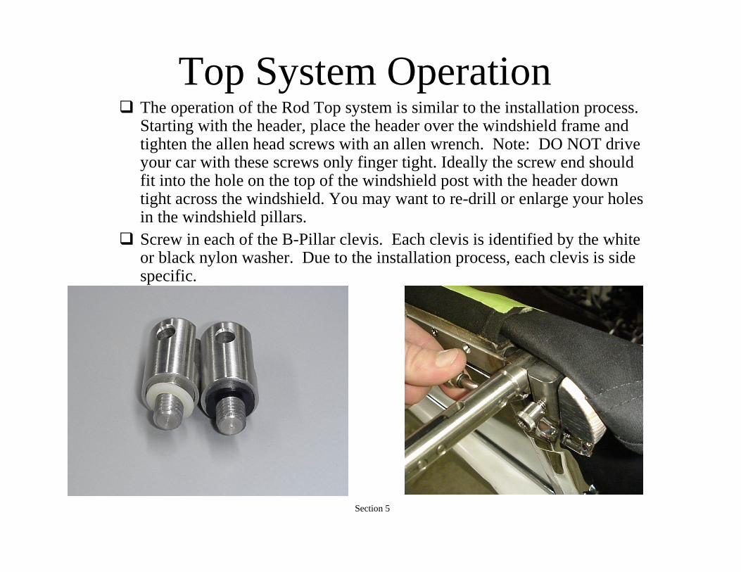
Top System Operation The operation of the Rod Top system is similar to the installation process.
Starting with the header, place the header over the windshield frame and tighten the allen head screws with an allen wrench. Note: DO NOT drive your car with these screws only finger tight. Ideally the screw end should fit into the hole on the top of the windshield post with the header down tight across the windshield. You may want to re-drill or enlarge your holes in the windshield pillars.
Screw in each of the B-Pillar clevis. Each clevis is identified by the white or black nylon washer. Due to the installation process, each clevis is side specific.
Section 5

Top System Operation Taking one of the top stack halves in the fully collapsed position.
Slide the A-Rail clevis onto the receiver at the header and pin in position.
Carefully unfold the top stack guiding the mounting flag into the clevis at the B-Pillar and pin in position, or pin to the stock flag. Carefully lower the section of beltline bow to the fully extended position.
Section 5.1
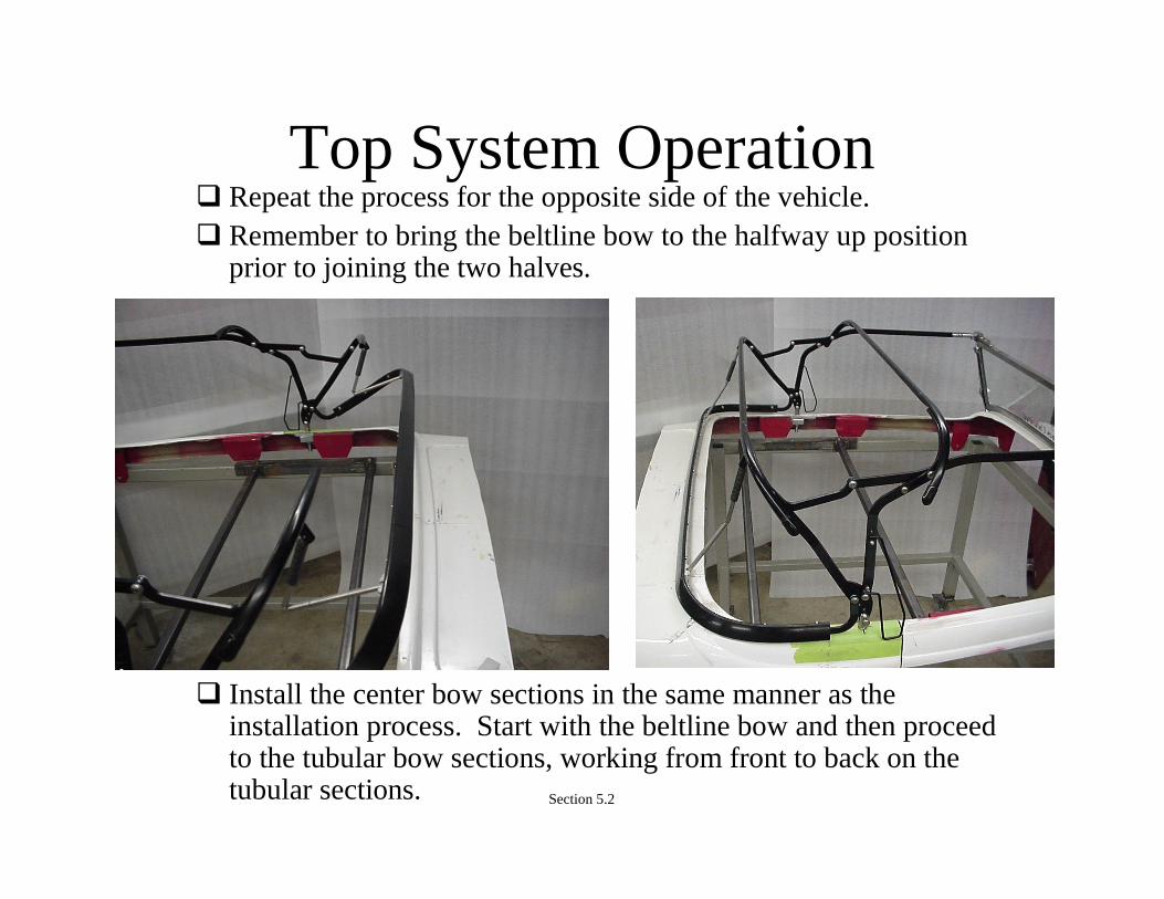
Top System Operation Repeat the process for the opposite side of the vehicle. Remember to bring the beltline bow to the halfway up position
prior to joining the two halves.
Install the center bow sections in the same manner as the installation process. Start with the beltline bow and then proceed to the tubular bow sections, working from front to back on the tubular sections. Section 5.2
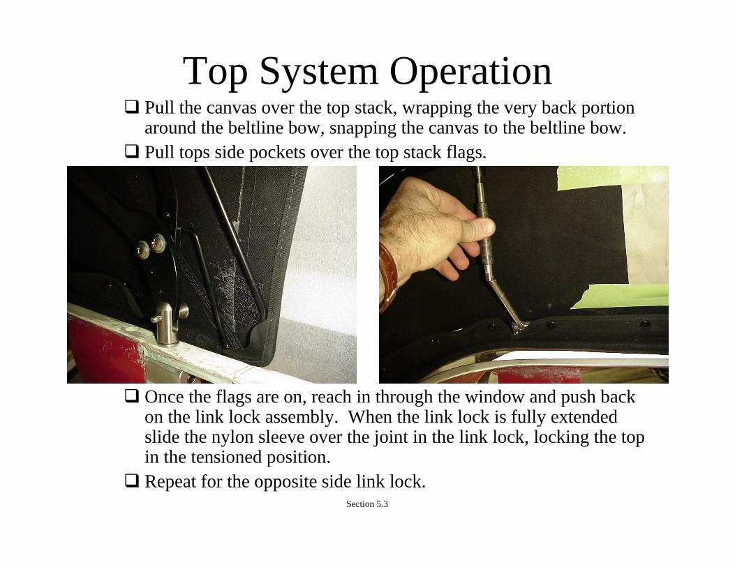
Top System Operation Pull the canvas over the top stack, wrapping the very back portion
around the beltline bow, snapping the canvas to the beltline bow. Pull tops side pockets over the top stack flags.
Once the flags are on, reach in through the window and push backon the link lock assembly. When the link lock is fully extendedslide the nylon sleeve over the joint in the link lock, locking the top in the tensioned position.
Repeat for the opposite side link lock. Section 5.3

Top System Operation The installation of the top is now complete.
The top can be removed by reversing the installation process andstoring the top in the trunk or the top may be removed as a completed assembly.
To remove the top as an assembly, start by releasing the link locks.
Loosen the screws holding the header brackets to the windshield posts.
Pull the pins from both of the B-rail clevis.
Lift straight up on the top assembly. It is highly recommended that two people complete the lifting and removal from the body.
Section 5.4

Top System Operation
For vehicles with the stock Ford mounting post you need to use the stock mounting kit (Part # 90-00228-00 From Rod Tops)
Be sure to use Lock-Tite on the threads of the bushing before permanently attaching it to the stock flag.
Note: You may wish to polish the stainless mounts before assembly
Section 5.5

Optional Zip-Out Window
• The Zip-Out Top has a material tension devise built in. The material only gets wrapped around the third bow and back to the zipper. This keeps the top from creeping forward when the rear backlight panel is out.
Section 6
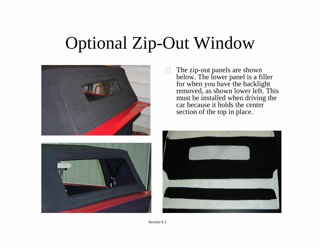
Optional Zip-Out Window• The zip-out panels are shown
below. The lower panel is a filler for when you have the backlight removed, as shown lower left. This must be installed when driving the car because it holds the center section of the top in place.
Section 6.1
Top Maintenance The Rod Top system is designed to require little maintenance. All
pivots used in the assemble of the top are stainless steel with self lubricating nylon bushings and should only need maintenance if damaged.
If for any reason, parts should ever need to be replaced or repaired, contact Time Machines Unlimited at 1-(888)-Rod-Tops for replacement parts.
The canvas on the top should be washed periodically to maintain its appearance.
Special attention should be paid to the welting sewn to the top in the area of the beltline bow. This is the portion of the top that contacts the body and should be kept free of dirt and abrasive contamination.
Use a mild detergent and water when cleaning the top. Allow topto fully dry prior to storing in supplied storage bag.
Section 7
Warranty Your Rod Top system is guaranteed to be free of manufacturers
defects. Any failures related to the manufacturing of the top up to one year from the date of sale will be repaired. To complete a warranty claim contact Time Machines Unlimited at 1-(888)-Rod-Tops and they will repair or replace any of the defective parts.
If any portion of the top system must be sent in for repair, the costs related to shipping are not covered under warranty. This is a parts and labor only warranty.
Section 8