rock support system in interaction with …bergforsk.se/wp-content/uploads/2011/08/e_nordlund.pdf1...
TRANSCRIPT
1
ROCK SUPPORT SYSTEM IN INTERACTION WITH THE ROCKINTERACTION WITH THE ROCK
BolidenP-I. Marklund, D. Sandström
LKABL. Malmgren
Luleå University of TechnologySenior Researchers: E Nordlund D Saiang P Zhang H Basarir MSenior Researchers: E. Nordlund, D. Saiang, P. Zhang, H. Basarir, M.
PhD students: Westblom, S. ShirzadeganResearch engineers: U. Nyberg (Swebrec)

2
The main design principle for rock support is to help the rock carry itselfis to help the rock carry itself
3
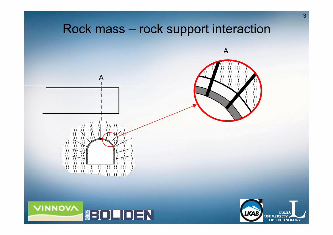
Rock mass – rock support interactionA
A

4
Rock mass – rock support interactionA
A
A

5
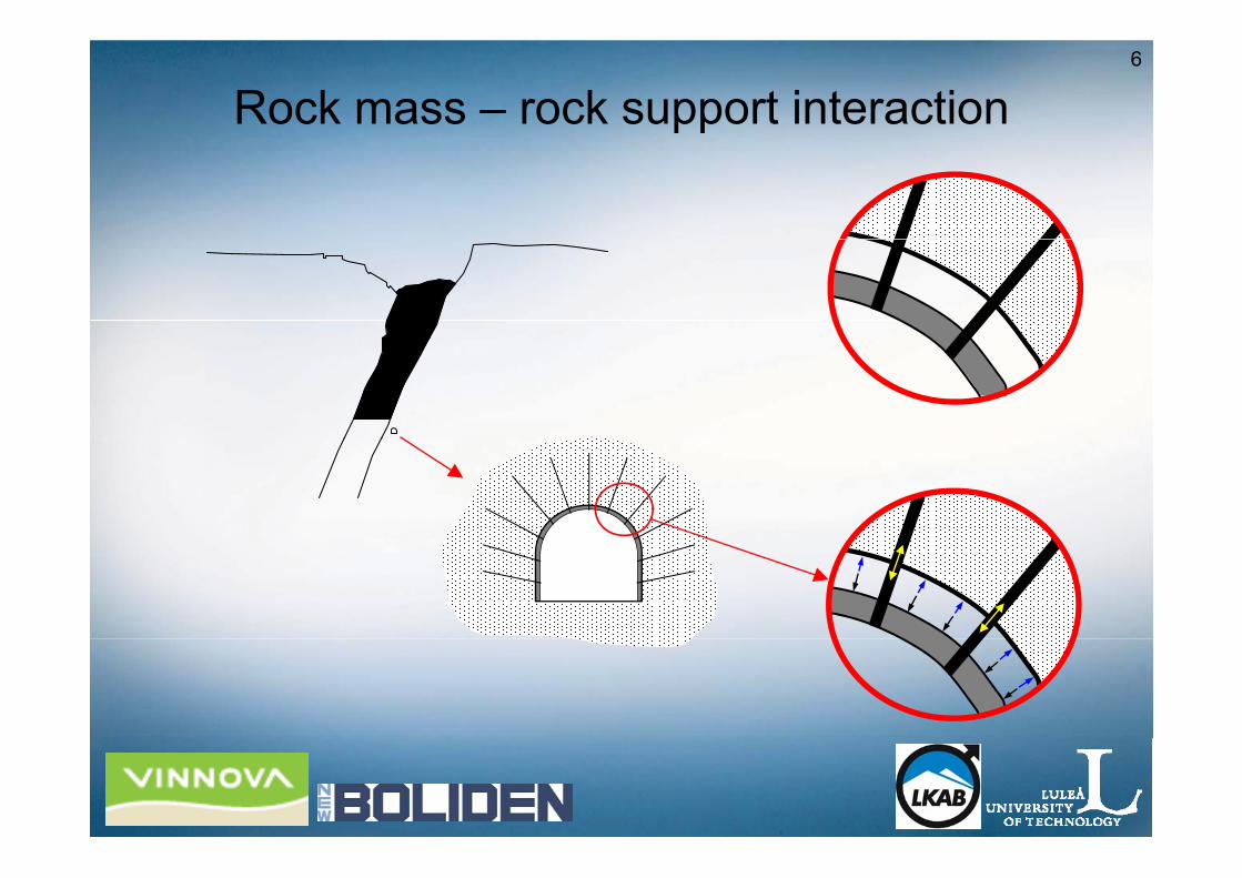
Rock mass – rock support interaction
6
Rock mass – rock support interaction
7Rock support – rock mass interactionObjectiveObjectiveGeneral• Improve the understanding of the interaction between the• Improve the understanding of the interaction between the
rock mass and the rock support system
Mining companies• Reduction of the number of production disturbances, thereby
decreasing the risk for personnel injury and productiondecreasing the risk for personnel injury and production losses.

8
Project outline
• Main activities– Field measurements – tests– Numerical analyses
• Sub projectp j– Weak rock and large deformations– Burst prone groundp g

9
The effect of uneveness of the The effect of uneveness of the tunnel/drift boundary
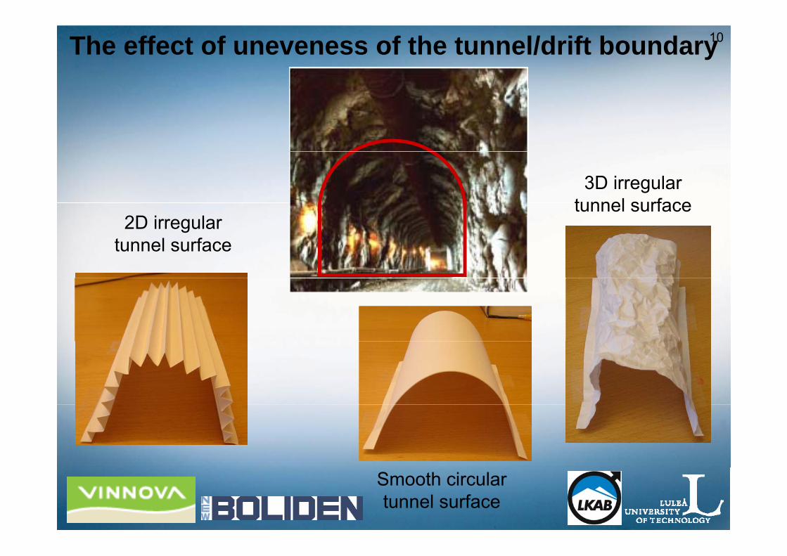
10The effect of uneveness of the tunnel/drift boundary
3D irregular tunnel surface
2D irregular tunnel surface
Smooth circular tunnel surface
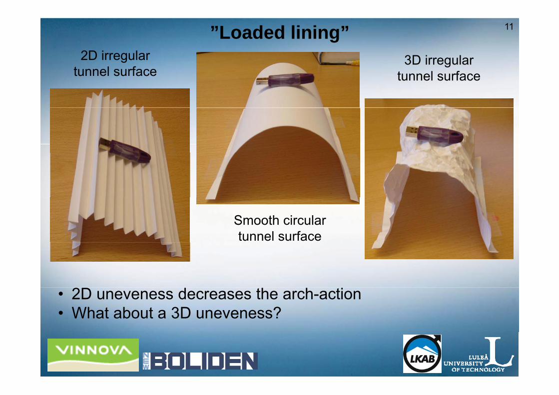
11”Loaded lining”2D irregular 3D irregular
tunnel surface3D irregular
tunnel surface
Smooth circular tunnel surface
• 2D uneveness decreases the arch-action • What about a 3D uneveness?

123DEC-model of physical model tests (Chang, 1994)
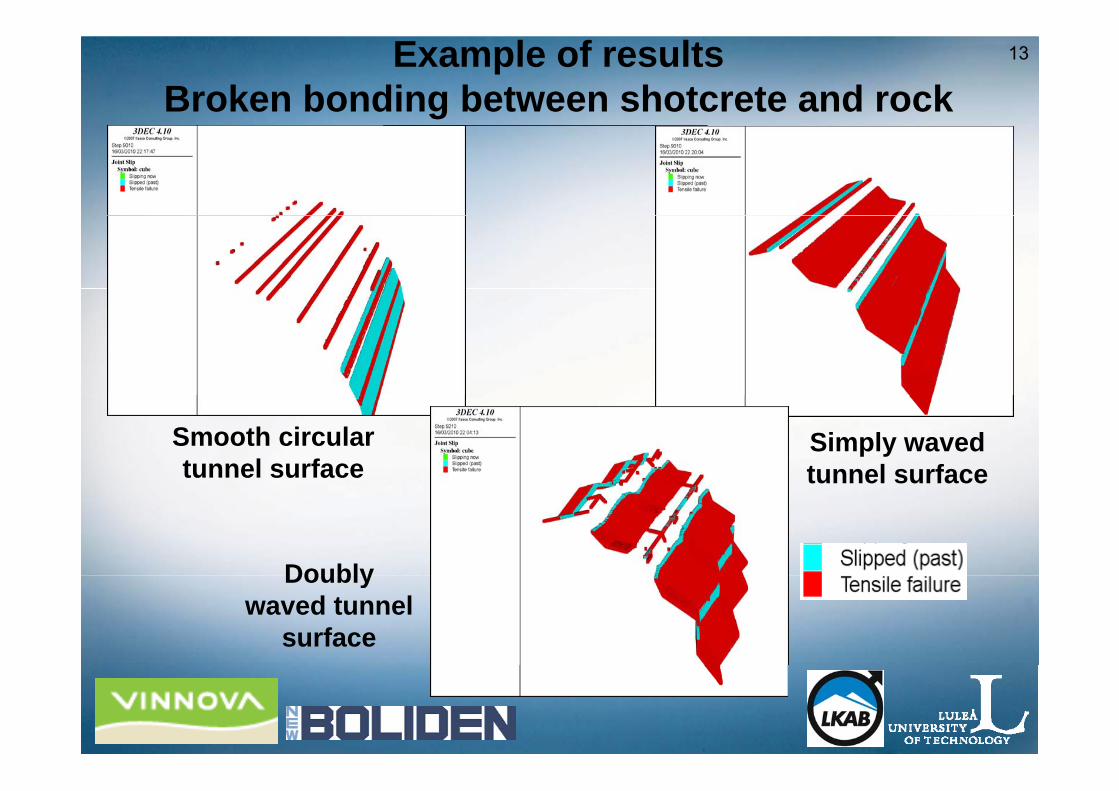
13Example of resultsBroken bonding between shotcrete and rock
Smooth circular tunnel surface
Simply waved tunnel surface
DoublyDoubly waved tunnel
surface

14
Conclusion – Initial analysis of rock surface uneveness
• We have to simulate the uneveness of the rock surface!
• Since 2D – seems to be more conservative, – requires less CPU time
we will use a 2D uneveness during the rest ofwe will use a 2D uneveness during the rest of the project.

15
Behaviour of drifts in weak rockBehaviour of drifts in weak rock

16
Squeezing conditions – Malmberget mine
17
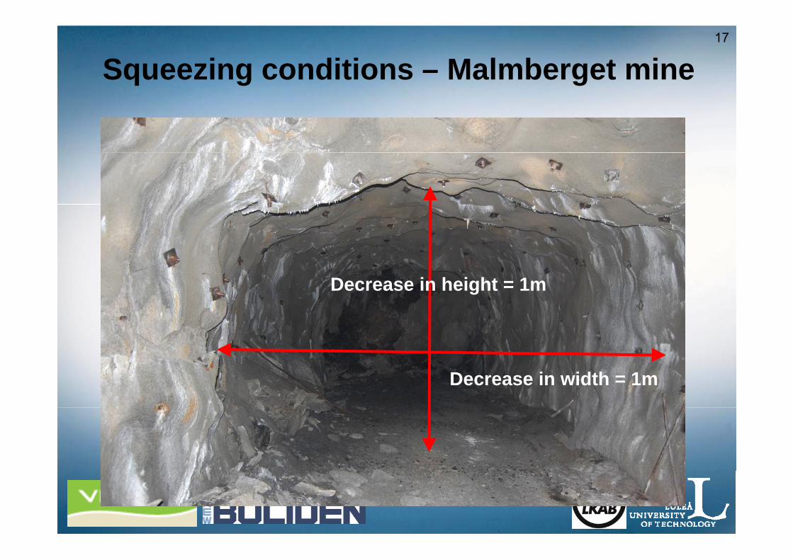
Squeezing conditions – Malmberget mine
D i h i ht 1Decrease in height = 1m
Decrease in width = 1m

18High stresses and low strength – large deformationsdeformations
Typical failure in the Kristineberg minemine

19
Field test on rock support in the Kristineberg pp gmine
• Increase the understanding of the interaction between the rock mass and the rock support system
• Evaluation of the D-bolt in the field – A bolt that can a uat o o t e bo t t e e d bo t t at cahandle large deformations
• Was carried out in March 2010• Was carried out in March 2010

20
Test area and measurement profiles10 rounds
• MeasurementsMeasurements− Length 50 m
− Every second round with D-bolt and every second with rebar
• Other activities• Other activities− Geological mapping of face and roof
Damage mapping− Damage mapping− Bore hole camera mapping (geology/damages)− Rock strength testsRock strength tests− Thickness measurements of shotcrete

21
Bolts, instruments, measurement points- a horizontal projection
High density profiles 2,3,6,7
Low density profiles 1 4 5 8 9 10Low density profiles 1,4,5,8,9,10
Extensometer / convergence profiles 2-3, 6-7
10 9 8 7 6 5 4 3 2 1 Measurement profiles

22
High density measurements profiles - D-bolt
Profiles 2 and 6
D-bolt
Convergence points for total station measurementsmeasurements
Strain gauged D-bolts
Convergence measurement with tape extensometerextensometer
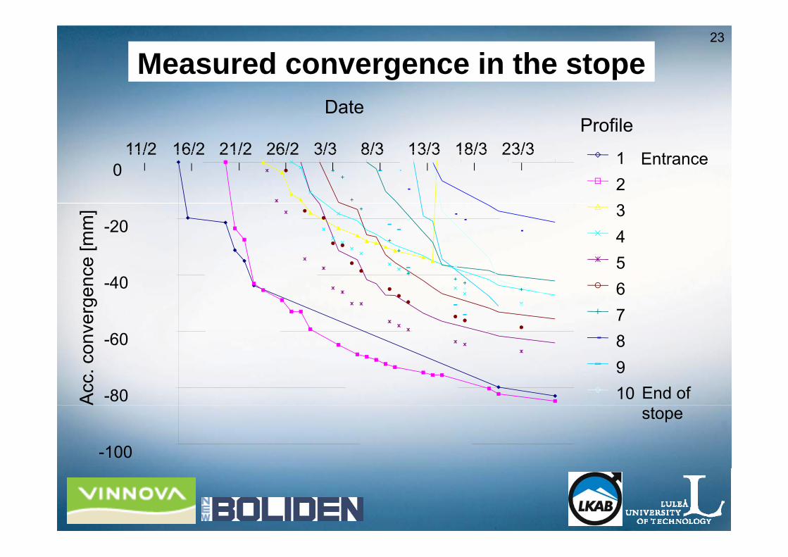
23
Measured convergence in the stope
1
ProfileDate
11/2 16/2 21/2 26/2 3/3 8/3 13/3 18/3 23/3 1 2 3
0
]
11/2 16/2 21/2 26/2 3/3 8/3 13/3 18/3 23/3 Entrance
3 45
40
-20
nce
[mm
678-60
-40
nver
gen
8910-80
60
Acc
. con
End of
-100
A
stope
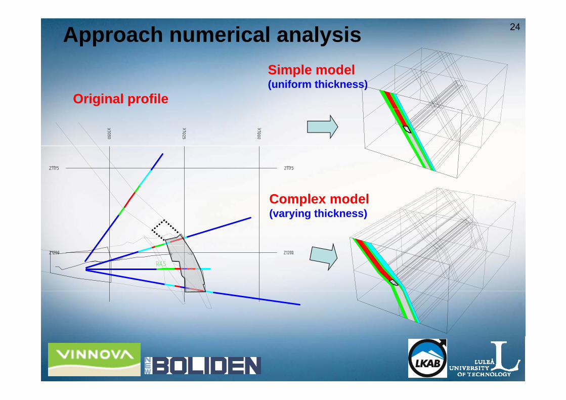
24Approach numerical analysis
Original profile
Simple model(uniform thickness)
Complex modelComplex model(varying thickness)
25Field measurements i Malmberget mine
• Test site: A development level• Measurement sections
– One density instrumented section per bolt type– One low density instrumented section on each side of the high
density instrumented sectiondensity instrumented section– One section with extensometers installed in connection to the high
density section• Three bolt types are planned to be tested:
– RebarS ll M 24 i il b lt– Swellex Mn24 or similar bolt
– Durabar• Instruments will be installed during the autumn 2010• Instruments will be installed during the autumn 2010
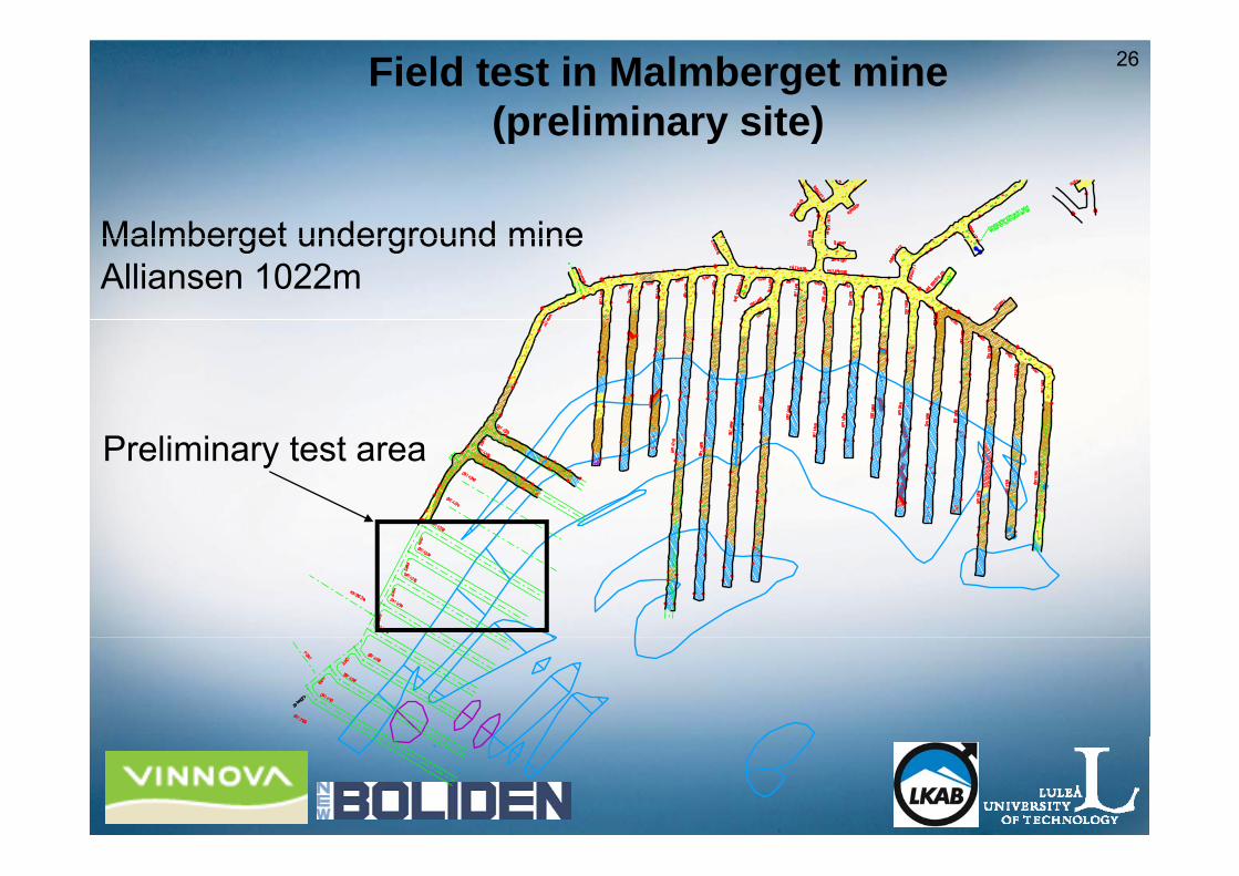
26Field test in Malmberget mine (preliminary site)(p y )
Malmberget underground mineMalmberget underground mineAlliansen 1022m
P li i t tPreliminary test area

27
Sub-project: Mine-induced seismicitySub project: Mine induced seismicity
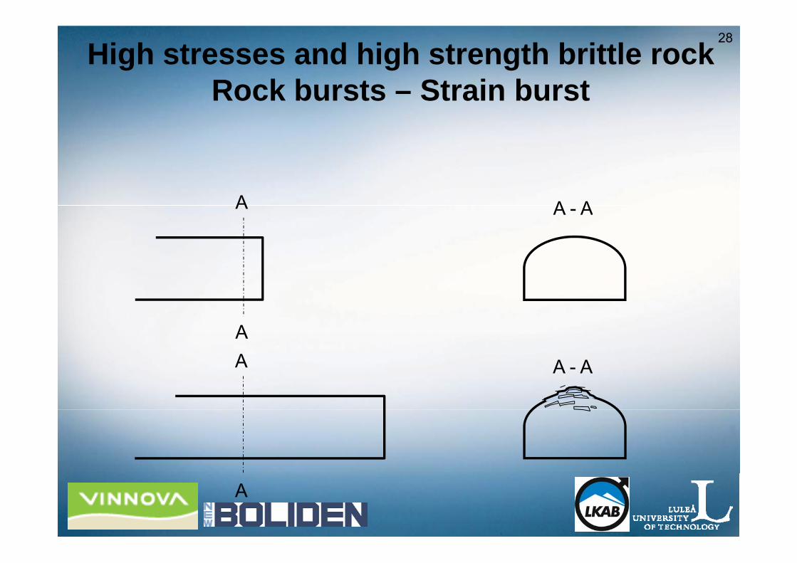
28High stresses and high strength brittle rock
Rock bursts Strain burstRock bursts – Strain burst
A A - A
AA A - A
A

29Damage caused by strain burst
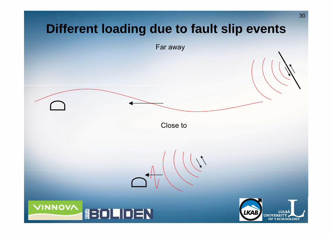
30
Different loading due to fault slip eventsFar away
Close to
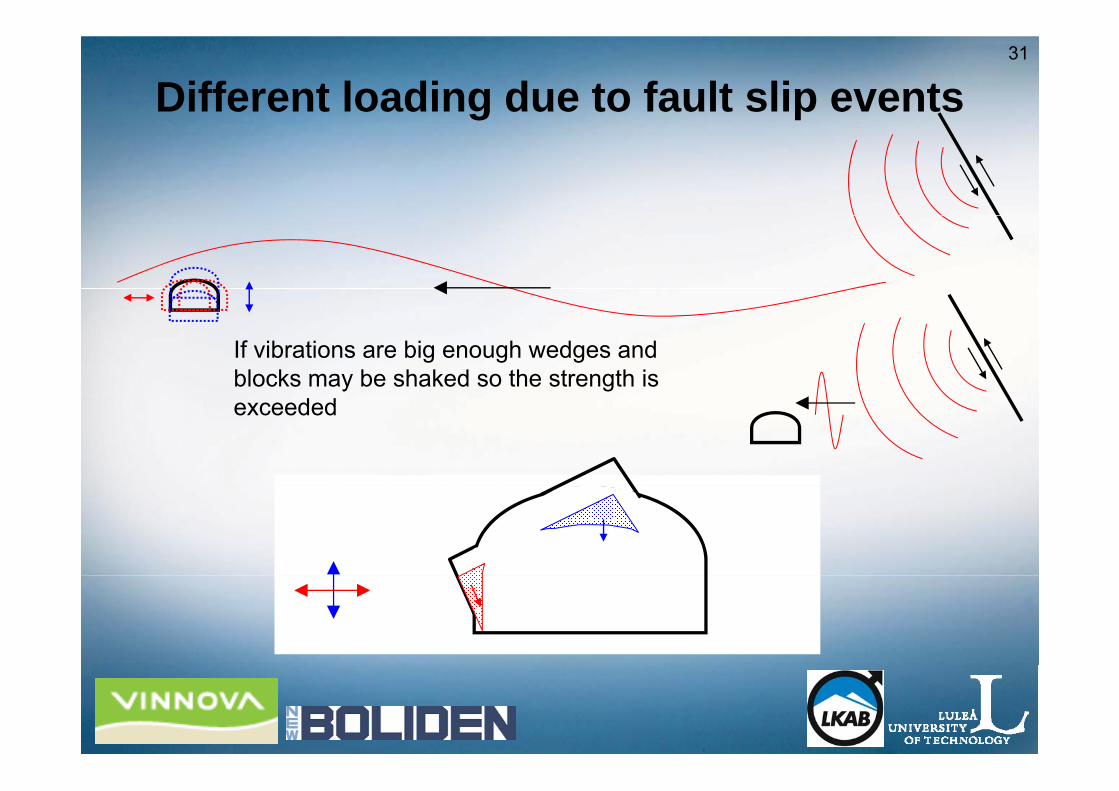
31
Different loading due to fault slip events
If vibrations are big enough wedges and blocks may be shaked so the strength is exceeded
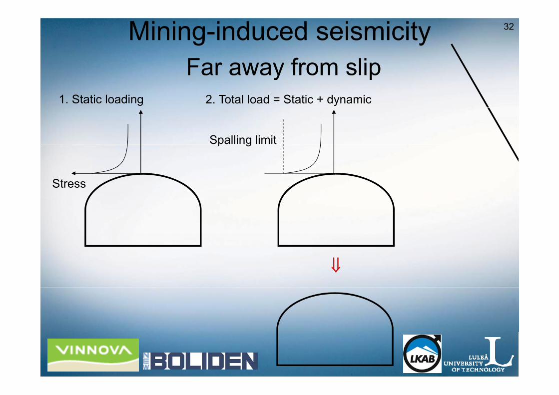
32Mining-induced seismicityFar away from slip
1. Static loading 2. Total load = Static + dynamic
Far away from slip
Spalling limit
Stress
⇓

33Mining-induced seismicityFar away from slip
1. Static loading
Far away from slip2. Total load = Static + dynamic
Spalling limit
Stress
⇓
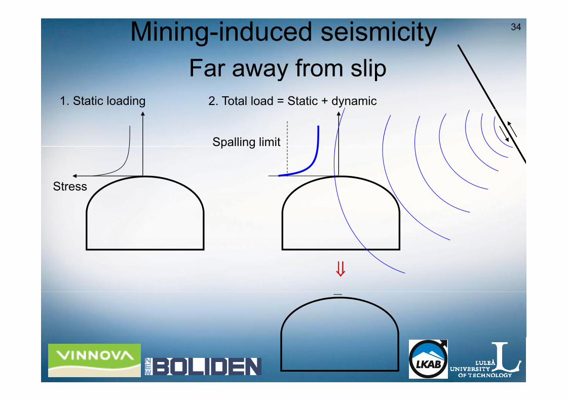
34Mining-induced seismicityFar away from slip
1. Static loading
Far away from slip2. Total load = Static + dynamic
Spalling limit
Stress
⇓

35Mining-induced seismicityFar away from slip
1. Static loading
Far away from slip2. Total load = Static + dynamic
Spalling limit
Stress
⇓
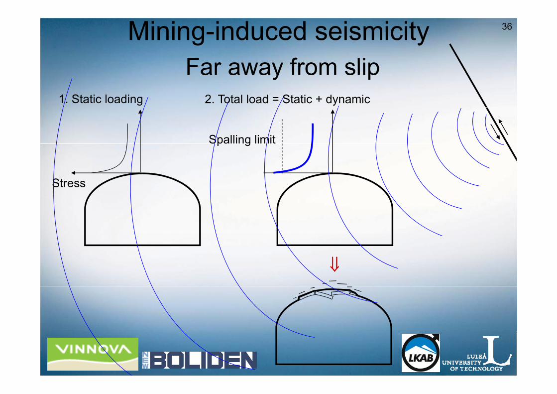
36Mining-induced seismicityFar away from slip
1. Static loading
Far away from slip2. Total load = Static + dynamic
Spalling limit
Stress
⇓

37Mining-induced seismicityFar away from slip
1. Static loading
Far away from slip2. Total load = Static + dynamic
Spalling limit
Stress
⇓

38
Mining induced seismicity
Close to slip

39
Mining induced seismicity - Close to slip
Wave from
Sliding along a geological structure
(fault) Wave from dynamic event
(fault)
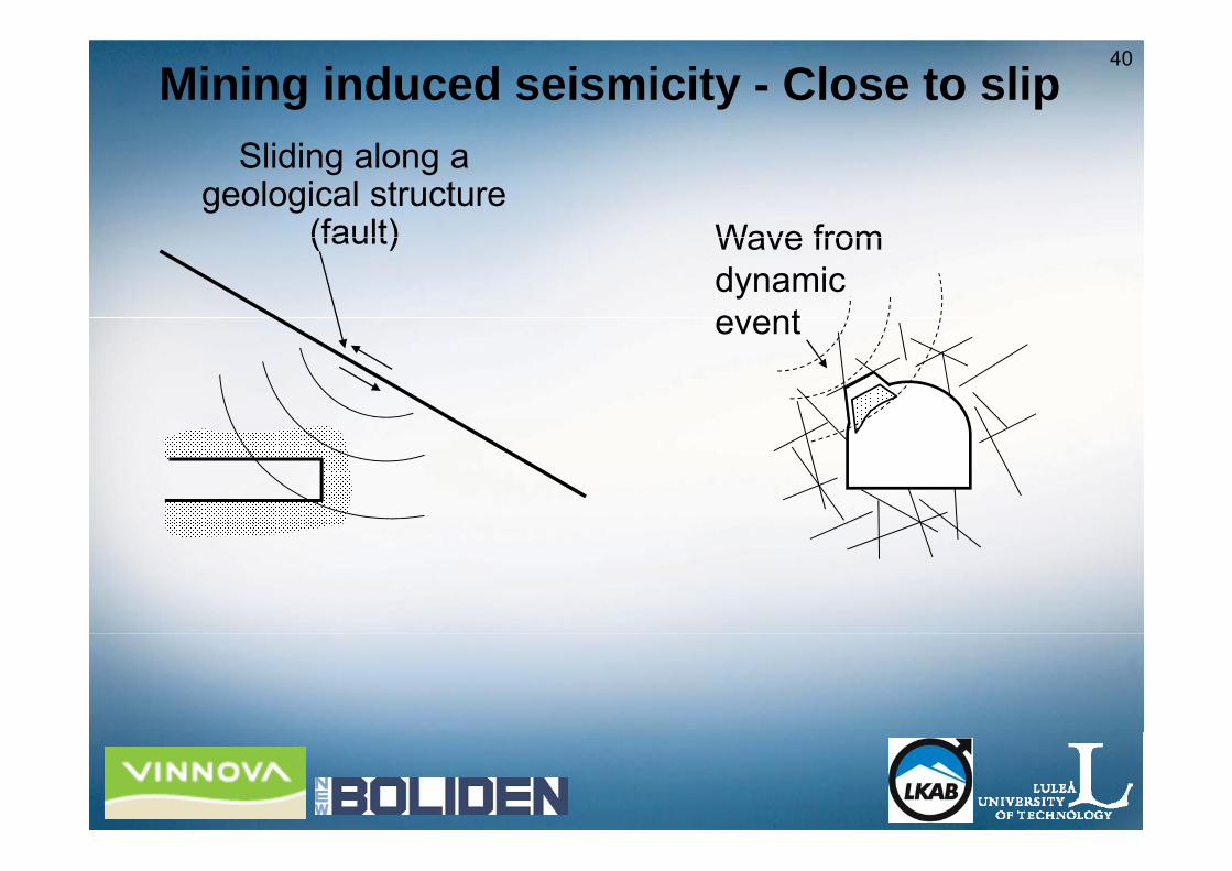
40
Mining induced seismicity - Close to slip
Wave from
Sliding along a geological structure
(fault) Wave from dynamic event
(fault)
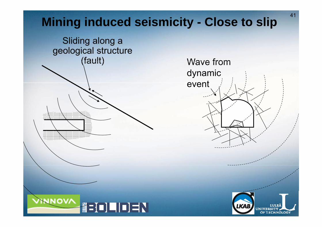
41
Mining induced seismicity - Close to slip
Wave from
Sliding along a geological structure
(fault) Wave from dynamic event
(fault)

42
Mining induced seismicity
• Strain bursts due to high static stressesF l t th f lt li t• Far away – close to the fault slip event– Superposition of static and dynamic stresses ⇒ Higher stress level exceeding the compressive strength
• Far away - close to fault slip eventShaking ⇒ Block and wedge fallouts– Shaking ⇒ Block and wedge fallouts
• Close to fault slip event– Ejection
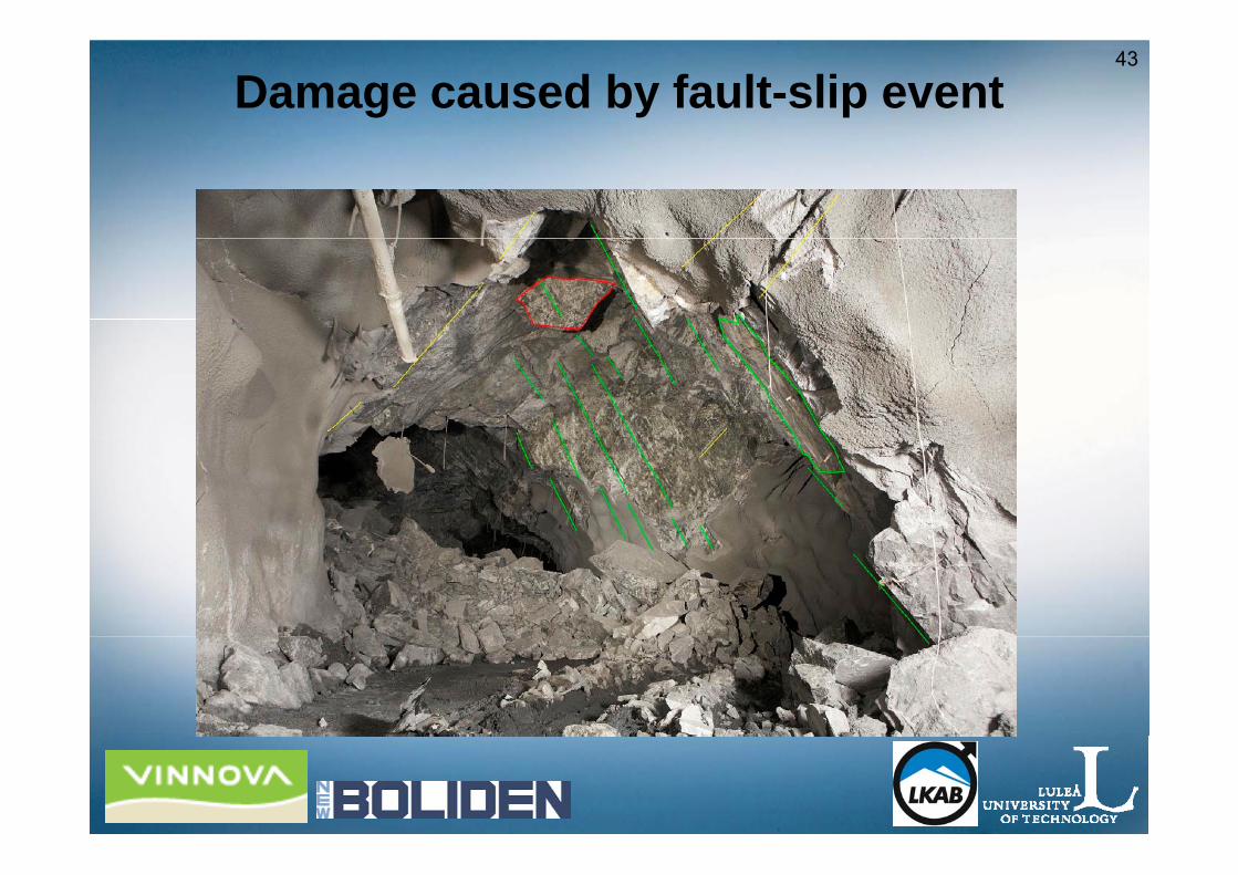
43
Damage caused by fault-slip event
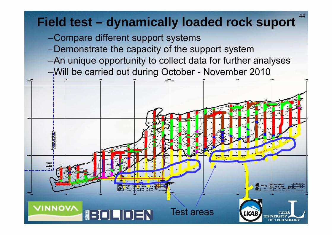
44Field test – dynamically loaded rock suportCompare different support systems−Compare different support systems
−Demonstrate the capacity of the support system−An unique opportunity to collect data for further analysesq pp y y−Will be carried out during October - November 2010
Test areas

45
Test site – Cross-cuts in the Kiirunavaara mine• ≈ 5x5 m2 per support system• ≈ 5x5 m per support system• Accelerometers• Laser spear to determine the velocity of the ejected rockp y j• High speed camera to record the behaviour
Th d i l d i i l t dThe dynamic load is simulatedby blasting.5m
5m
Blast hole
5m5-10m
7m
T t d t t
3 - 4 m3 - 4 m
Tested support systemHigh speed camera

46Numerical analysis of seismically loaded
openingsopenings
Response of a drift• Response of a drift exposed to different wave typestypes
• Response of drifts exposed to seismic loadsto seismic loads

47
…Thank you!!