roche applied science technical notecustomized dual color applications that use hybprobe probes...
TRANSCRIPT
Color Compensation
The LightCycler System is able to simultaneously detect and analyze more than onecolor in each capillary. Due to overlap of the emission spectra of the dyes, onechannel picks up signals (crosstalk) from a dye measured by another channel. Thisbleed-over of fluorescence signal can result in data that cannot be interpreted. Tocorrect the bleed-over, color compensation can be applied either during an experi-mental run or before data analysis. When color compensation is activated,LightCycler algorithms use the data from a so-called ccc file (LightCycler SW 3.5)or ccc object (LightCycler SW 4.0) to compensate for the fluorescence crosstalk.
This Technical Note will show you how to create color compensation for dual coloranalyses with LC Red 640 and LC Red 705. In addition, it describes the color com-pensation procedure for multiplex assays.
Note: Color compensation for multiplex assays can only be done on the LightCycler2.0 Instrument.
Note: Methods of color compensation for Dual Color Hydrolysis Assays (conven-tionally called “TaqMan” Assays) will be found in Technical Note No. LC 21,“Hydrolysis Probe (‘TaqMan’) Assays with the LightCycler System.”
Purpose of this Note
Table of Contents
Roche Applied Science
Technical NoteNo. LC 19/2004
Basic Information about Color Compensation 2
Generating Color Compensation 4-6Color Compensation for Dual Color Applications that Use LightCycler Red 640 and LightCycler Red 705 Creating Color Compensation Files with SW 3.5Creating Color Compensation Objects with SW 4.0
Color Compensation for Customized Applications 7
Applications Using Customized Dual Color Hybridization Probes 8
Multicolor Hybridization Probe Applications 8-10
Application Example 11
2593 LC TN 19-2004_ak1 21.10.2004 10:57 Uhr Seite 1
1. Basic Information about Color Compensation
The LightCycler System can detect two or more different sequences in one sample, e.g., both atarget and an internal control. Such assays require two specific sets of hybridization probes,each labeled with different FRET (Fluorescence Resonance Energy Transfer) acceptor dyes.Example: For dual color detection, one of the two hybridization probe sets uses LightCyclerRed 640 as acceptor dye; the other uses LightCycler Red 705. Both acceptor dyes are excited bythe donor dye fluorescein. These red dyes have different emission spectra, which allows theLightCycler Instrument to detect the distinctive signal from each set in different fluorimeterchannels.The LightCycler 2.0 Instrument has additional detection channels that make it possible to per-form multicolor (e.g. multiplex hybridization probe) assays with four different acceptor dyes:LightCycler Red 610, LightCycler Red 640, LightCycler Red 670 and LightCycler Red 705.Note: For more details of hybridization probe chemistry please read Technical Note No.LC 18/2004, “Assay Formats for Use in Real-Time PCR.”
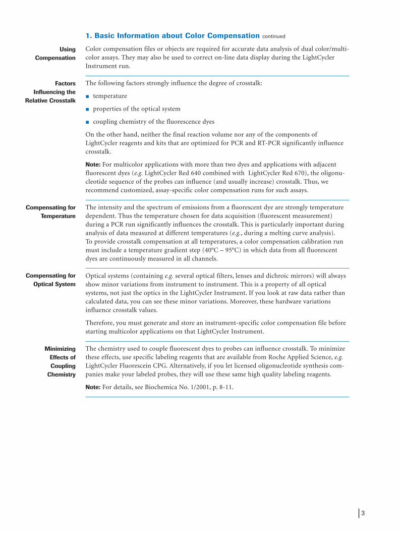
Although the optical filters of each detection channel are optimized for different emissionmaxima, all fluorescent dyes currently available have emission spectra with long “tails,” leadingto a spectral overlap. As depicted in Figure 1, the emission spectrum of the donor dye (fluores-cein) slightly overlaps the emission spectrum of LightCycler Red 640, which, in turn, overlapsthe LightCycler Red 705 emission spectrum.
� Figure 1: Overlap of emission spectra from fluorescent dyes used in the LightCycler System.
The gray vertical bars in Figure 1 show the width of the detection windows in the 530 nm, 640nm and 705 nm channels of the LightCycler. The hatched areas below these bars represent thebleed-over (overlap) of the fluorescein and LightCycler Red 640 signals into other channels.There is especially significant overlap of the 640 nm signal into the 705 nm channel.
You can easily correct the spectral overlap described above by calibrating the instrument withthe LightCycler Color Compensation Set (Cat. No. 2 158 850, for dual color applications thatuse LightCycler-Red 640 and LightCycler-Red 705) or by customized calibration (for applica-tions that use the additional channels of the LightCycler 2.0 Instrument). During a calibrationrun, the LightCycler Instrument measures the fluorescence of each dye in all channels andgenerates an instrument-specific color-compensation file (or object). Later, the software auto-matically uses this so-called ccc file or ccc object to reassign the fluorescence in each channelto the appropriate dye. The net result is detection of only one dye signal in each channel.
Note: Color compensation is only necessary when you run an experiment with two or moredifferent dyes in one capillary. Color compensation is not required when the experiment usesonly a single dye (e.g., SYBR Green I or LightCycler Red 640).
Continued on next page
Dyes andDetection Channels
Spectral Overlap
Calibration withColor
Compensation
2
2593 LC TN 19-2004_ak1 21.10.2004 10:57 Uhr Seite 2
UsingCompensation
FactorsInfluencing the
Relative Crosstalk
Compensating for Temperature
Compensating forOptical System
MinimizingEffects of Coupling
Chemistry
3
1. Basic Information about Color Compensation continued
Color compensation files or objects are required for accurate data analysis of dual color/multi-color assays. They may also be used to correct on-line data display during the LightCyclerInstrument run.
The following factors strongly influence the degree of crosstalk:
� temperature
� properties of the optical system
� coupling chemistry of the fluorescence dyes
On the other hand, neither the final reaction volume nor any of the components ofLightCycler reagents and kits that are optimized for PCR and RT-PCR significantly influencecrosstalk.
Note: For multicolor applications with more than two dyes and applications with adjacentfluorescent dyes (e.g. LightCycler Red 640 combined with LightCycler Red 670), the oligonu-cleotide sequence of the probes can influence (and usually increase) crosstalk. Thus, werecommend customized, assay-specific color compensation runs for such assays.
The intensity and the spectrum of emissions from a fluorescent dye are strongly temperaturedependent. Thus the temperature chosen for data acquisition (fluorescent measurement)during a PCR run significantly influences the crosstalk. This is particularly important duringanalysis of data measured at different temperatures (e.g., during a melting curve analysis).To provide crosstalk compensation at all temperatures, a color compensation calibration runmust include a temperature gradient step (40°C – 95°C) in which data from all fluorescentdyes are continuously measured in all channels.
Optical systems (containing e.g. several optical filters, lenses and dichroic mirrors) will alwaysshow minor variations from instrument to instrument. This is a property of all opticalsystems, not just the optics in the LightCycler Instrument. If you look at raw data rather thancalculated data, you can see these minor variations. Moreover, these hardware variationsinfluence crosstalk values.
Therefore, you must generate and store an instrument-specific color compensation file beforestarting multicolor applications on that LightCycler Instrument.
The chemistry used to couple fluorescent dyes to probes can influence crosstalk. To minimizethese effects, use specific labeling reagents that are available from Roche Applied Science, e.g.LightCycler Fluorescein CPG. Alternatively, if you let licensed oligonucleotide synthesis com-panies make your labeled probes, they will use these same high quality labeling reagents.
Note: For details, see Biochemica No. 1/2001, p. 8-11.
2593 LC TN 19-2004_ak1 21.10.2004 10:57 Uhr Seite 3
2. Generating Color Compensation
You can create an instrument-specific color compensation file (or object) for:
� Dual color applications that use LightCycler Red 640 and LightCycler Red 705Note: Prepare this ccc file/object with the ready-to-use LightCycler Color CompensationSet. The LightCycler Software provides pre-defined protocols for this color compensationrun. For details, see sections 2.1.1 and 2.1.2.
� Customized dual color applications that use HybProbe probes labeled with other dye combinations
� Customized multicolor applications (e.g., multiplex PCR or multicolor detection)
Note: Applications involving dyes other than Red 640 and Red 705 can only be used in the LightCycler 2.0 Instrument.
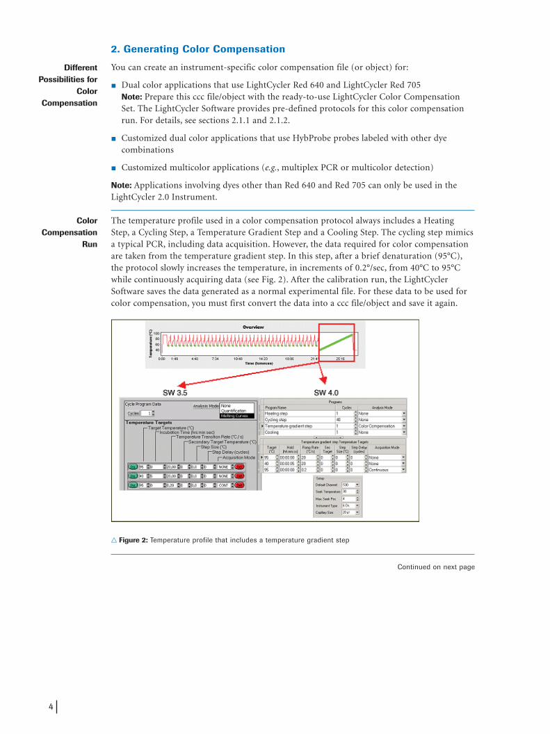
The temperature profile used in a color compensation protocol always includes a HeatingStep, a Cycling Step, a Temperature Gradient Step and a Cooling Step. The cycling step mimicsa typical PCR, including data acquisition. However, the data required for color compensationare taken from the temperature gradient step. In this step, after a brief denaturation (95°C),the protocol slowly increases the temperature, in increments of 0.2°/sec, from 40°C to 95°Cwhile continuously acquiring data (see Fig. 2). After the calibration run, the LightCyclerSoftware saves the data generated as a normal experimental file. For these data to be used forcolor compensation, you must first convert the data into a ccc file/object and save it again.
� Figure 2: Temperature profile that includes a temperature gradient step
Continued on next page
DifferentPossibilities for
ColorCompensation
ColorCompensation
Run
4
2593 LC TN 19-2004_ak1 21.10.2004 10:58 Uhr Seite 4
2.1 Color Compensation for Dual Color Applications that UseLightCycler Red 640 and LightCycler Red 705
The following sections describe how to prepare a color compensation file for a dual colorexperiment (using LC 640 and LC 705) on two different versions of the LightCycler Software,SW 3.5 and SW 4.0.
You only need to use the LightCycler Color Compensation Set once to generate a color com-pensation file or color compensation object that can be used for all dual color (LC 640/LC705) experiments on that instrument. The only times you need to generate a new cccfile/object are when you update the software or after the optical system has been repaired.
The set contains four vials of ready-to-use solutions:
� Vial 1: standard buffer
� Vial 2-4: standard oligonucleotides labeled with either fluorescein (3´ end; Vial 2),LightCycler Red 640 (5´ end; Vial 3) or LightCycler Red 705 (5´ end; Vial 4).
2.1.1 Creating Color Compensation Files with SW 3.5
For details on running the color compensation experiment, see the pack insert of theLightCycler Color Compensation Set (new Cat. No. 02 158 850 001) and the LightCyclerOperator’s Manual. To perform the color compensation calibration experiment, use thecalibration.exp file, which you can find in the “Demo Protocol” folder under “Demo Data.”It contains all the necessary sample information.
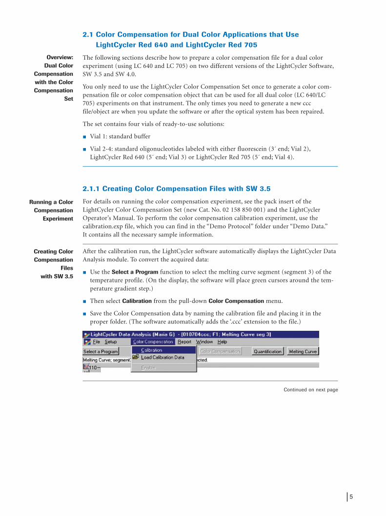
After the calibration run, the LightCycler software automatically displays the LightCycler DataAnalysis module. To convert the acquired data:
� Use the Select a Program function to select the melting curve segment (segment 3) of thetemperature profile. (On the display, the software will place green cursors around the tem-perature gradient step.)
� Then select Calibration from the pull-down Color Compensation menu.
� Save the Color Compensation data by naming the calibration file and placing it in theproper folder. (The software automatically adds the ‘.ccc’ extension to the file.)
Continued on next page
Overview: Dual Color
Compensationwith the Color Compensation
Set
Running a Color Compensation
Experiment
Creating Color Compensation
Files with SW 3.5
5
2593 LC TN 19-2004_ak1 21.10.2004 10:58 Uhr Seite 5
2.1.1 Creating Color Compensation Files with SW 3.5 continued
You can activate the stored color compensation file (*.ccc file) at several points in theLightCycler Protocol to provide color compensation for raw data:
� On-line color compensationYou can load the *.ccc file during a run on the LightCycler Instrument to correct the on-line display of data. Just click on Choose CCC File and select the appropriate file.
� Color compensation for data analysisYou can load and activate the *.ccc file to compensate for crosstalk between channel 2 andchannel 3 during dual color analysis. Before starting this analysis, just select LoadCalibration Data on the Color Compensation menu, then select the appropriate file.
2.1.2 Creating Color Compensation Objects with SW 4.0
For details on running the color compensation experiment, see the pack insert of theLightCycler Color Compensation Set (new Cat. No. 02 158 850 001) and the LightCyclerOperator’s Manual. To create the color compensation object, use the macro for automaticexecution of the calibration, which is included in the “Roche” folder under “Templates andMacros” / “Experiment Macros” / “Demo Macros” / “Color Compensation Set (Cat No 2 158 850)”. Follow the instructions provided by the Experiment Kit Wizard.
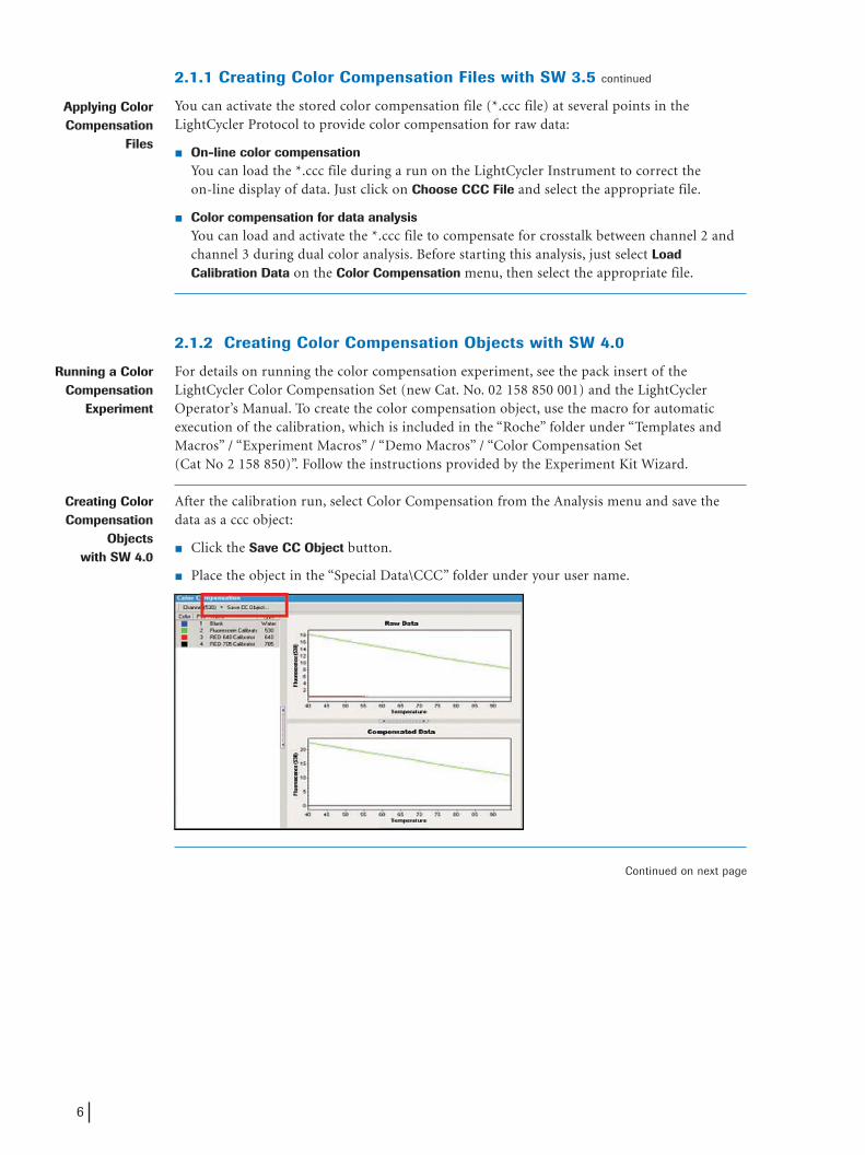
After the calibration run, select Color Compensation from the Analysis menu and save thedata as a ccc object:
� Click the Save CC Object button.
� Place the object in the “Special Data\CCC” folder under your user name.
Continued on next page
Applying Color Compensation
Files
Running a Color Compensation
Experiment
Creating Color Compensation
Objects with SW 4.0
6
2593 LC TN 19-2004_ak1 21.10.2004 10:58 Uhr Seite 6
2.1.2 Creating Color Compensation Objects with SW 4.0 continued
You can apply the stored color compensation object to all dual color HybProbe experimentswhich use the same dye combination (Red 640/Red 705) by doing the following:
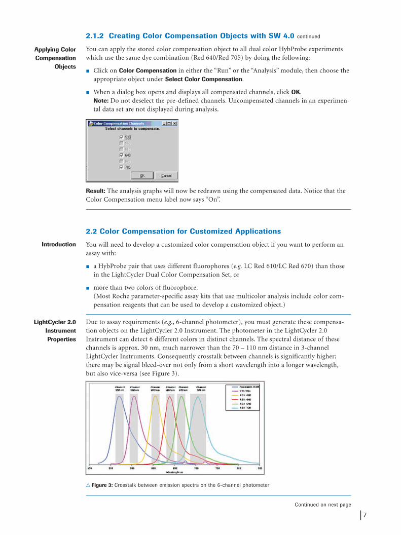
� Click on Color Compensation in either the “Run” or the “Analysis” module, then choose theappropriate object under Select Color Compensation.
� When a dialog box opens and displays all compensated channels, click OK.Note: Do not deselect the pre-defined channels. Uncompensated channels in an experimen-tal data set are not displayed during analysis.
Result: The analysis graphs will now be redrawn using the compensated data. Notice that theColor Compensation menu label now says “On”.
2.2 Color Compensation for Customized Applications
You will need to develop a customized color compensation object if you want to perform anassay with:
� a HybProbe pair that uses different fluorophores (e.g. LC Red 610/LC Red 670) than thosein the LightCycler Dual Color Compensation Set, or
� more than two colors of fluorophore.(Most Roche parameter-specific assay kits that use multicolor analysis include color com-pensation reagents that can be used to develop a customized object.)
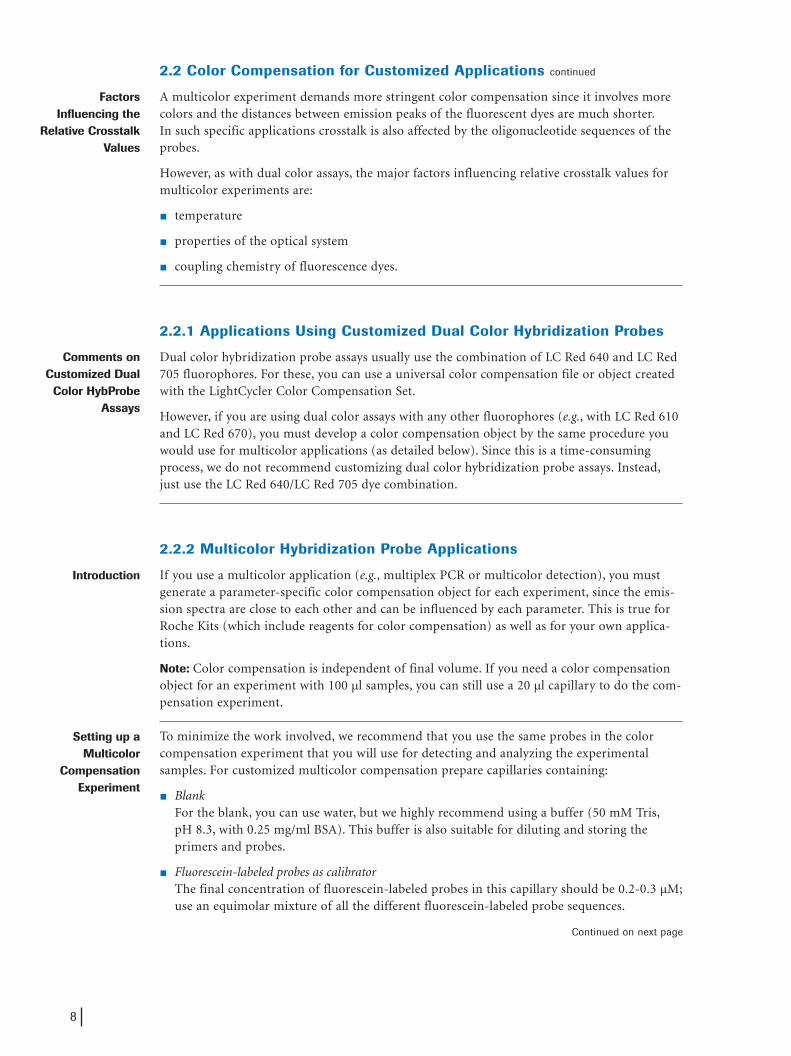
Due to assay requirements (e.g., 6-channel photometer), you must generate these compensa-tion objects on the LightCycler 2.0 Instrument. The photometer in the LightCycler 2.0Instrument can detect 6 different colors in distinct channels. The spectral distance of thesechannels is approx. 30 nm, much narrower than the 70 – 110 nm distance in 3-channelLightCycler Instruments. Consequently crosstalk between channels is significantly higher;there may be signal bleed-over not only from a short wavelength into a longer wavelength,but also vice-versa (see Figure 3).
� Figure 3: Crosstalk between emission spectra on the 6-channel photometer
Continued on next page
Applying Color Compensation
Objects
Introduction
LightCycler 2.0InstrumentProperties
7
2593 LC TN 19-2004_ak1 21.10.2004 10:58 Uhr Seite 7
2.2 Color Compensation for Customized Applications continued
A multicolor experiment demands more stringent color compensation since it involves morecolors and the distances between emission peaks of the fluorescent dyes are much shorter.In such specific applications crosstalk is also affected by the oligonucleotide sequences of theprobes.
However, as with dual color assays, the major factors influencing relative crosstalk values formulticolor experiments are:
� temperature
� properties of the optical system
� coupling chemistry of fluorescence dyes.
2.2.1 Applications Using Customized Dual Color Hybridization Probes
Dual color hybridization probe assays usually use the combination of LC Red 640 and LC Red705 fluorophores. For these, you can use a universal color compensation file or object createdwith the LightCycler Color Compensation Set.
However, if you are using dual color assays with any other fluorophores (e.g., with LC Red 610and LC Red 670), you must develop a color compensation object by the same procedure youwould use for multicolor applications (as detailed below). Since this is a time-consumingprocess, we do not recommend customizing dual color hybridization probe assays. Instead,just use the LC Red 640/LC Red 705 dye combination.
2.2.2 Multicolor Hybridization Probe Applications
If you use a multicolor application (e.g., multiplex PCR or multicolor detection), you mustgenerate a parameter-specific color compensation object for each experiment, since the emis-sion spectra are close to each other and can be influenced by each parameter. This is true forRoche Kits (which include reagents for color compensation) as well as for your own applica-tions.
Note: Color compensation is independent of final volume. If you need a color compensationobject for an experiment with 100 µl samples, you can still use a 20 µl capillary to do the com-pensation experiment.
To minimize the work involved, we recommend that you use the same probes in the colorcompensation experiment that you will use for detecting and analyzing the experimentalsamples. For customized multicolor compensation prepare capillaries containing:
� BlankFor the blank, you can use water, but we highly recommend using a buffer (50 mM Tris,pH 8.3, with 0.25 mg/ml BSA). This buffer is also suitable for diluting and storing theprimers and probes.
� Fluorescein-labeled probes as calibratorThe final concentration of fluorescein-labeled probes in this capillary should be 0.2-0.3 µM;use an equimolar mixture of all the different fluorescein-labeled probe sequences.
Continued on next page
FactorsInfluencing the
Relative CrosstalkValues
Comments onCustomized Dual
Color HybProbe Assays
Introduction
Setting up aMulticolor
CompensationExperiment
8
2593 LC TN 19-2004_ak1 21.10.2004 10:58 Uhr Seite 8

2.2.2 Multicolor Hybridization Probe Applications continued
� LC-Red-labeled probes as calibratorsEach LC-Red-labeled probe should have its own capillary. (If you have more than one probewith the same LC-Red dye, use an equimolar mixture of all those probes in the same capil-lary.) Due to absence of a FRET partner, the signal intensity of the probe will be low.Therefore, use a final probe concentration of at least 1 µM.
Note: You can include up to 6 capillaries (blank, Fluorescein, LC Red 610, LC Red 640, LC Red670 and LC Red 705) in the run.
Since the spectral distance between channels in the LightCycler 2.0 Instrument is short, chan-nels might, in rare cases, pick up faint signals from neighboring channels, even after colorcompensation is activated. These signals are usually very small and are just slightly abovebackground noise. To eliminate these artifacts, slowly reduce (by stepwise titration) the finalconcentration of Hybridization Probes in the color compensation run to the concentrationused in the experimental assay (e.g., 0.2 µM each). Alternatively, use the non-automated analy-sis method (Fit Points) to manually raise the noise band.
The multicolor compensation protocol is identical to that of the LightCycler ColorCompensation Set. If you are an expert user, you may copy the macro from the Demo Macrofolder (see 2.1.2), save it under a new name, and then change the settings in the Sample List(under Capillary View).
Important: If a multicolor compensation object is to work properly, you must edit the analysis-specific sample list in the “Color Compensation” module. Most importantly, you must definethe dominant channels (Figure 4).
� Figure 4: Using and editing a macro for multicolor color compensation
� Before starting the run, place the reagent capillaries into the carousel in the order listedabove. Always place the capillary with buffer in the first position on the carousel.
� When the experiment is finished, select Color Compensation from the “Analysis” menu andthen Save the CC Object (as in section 2.1.2).
Continued on next page
SpecialConsiderations
Creating Color Compensation
Objects
9
2593 LC TN 19-2004_ak1 21.10.2004 10:58 Uhr Seite 9

2.2.2 Multicolor Hybridization Probe Applications continued
You can now apply the parameter-specific color compensation object to the correspondingmulticolor experiments. To activate the color compensation, click on Color Compensation ineither the “Run” or the “Analysis” module, and choose the appropriate object under SelectColor Compensation.
Note: Select the appropriate channels for multicolor compensation, then click OK.
Important: This color compensation will be valid for all experiments performed with the iden-tical parameters.
However, if you change the sequences of the hybridization probes, you will need to generate anew color compensation object. Even if you order a new batch of “identical” probes, it may bewise to re-run the color compensation experiment and compare the results obtained with thefreshly generated ccc object to those obtained with the old ccc object.
The LightCycler SW version 4.0 and higher provides the option for an automated selection ofa specific color compensation object. In the Capillary View under Samples there are severalboxes offering room for additional run and/or sample information.
The box for the color compensation identnumber (Color Comp ID) can be used to link ananalysis file to the respective parameter-specific color compensation object. Especially whenworking with Macros, this ID number is highly convenient for the correct identification ofcolor compensation objects.
Example: Using the Demo Macro “Color Compensation Set (Cat No 2 158 850)” for a dualcolor calibration run (LC Red 640 and 705), this Macro automatically labels the generatedccc.object with the Color Comp ID “02158850”. Any dual color run using this ccc.object canbe automatically guided to this ccc.object by entering the identical number into the ColorComp ID box. The same function is available for customized applications. The ID box acceptsany numbers, letters or letter-figure combinations.
Applying Color Compensation to
a MulticolorHybridization
Probe Experiment
AutomatedIdentification of
Specific ColorCompensation
Objects by Usingthe "Color Comp
ID” Number
10
2593 LC TN 19-2004_ak1 21.10.2004 10:58 Uhr Seite 10
3. Application Example
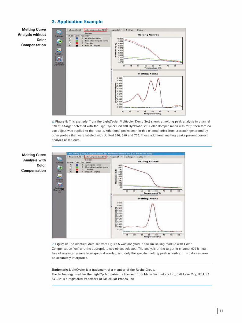
� Figure 5: This example (from the LightCycler Multicolor Demo Set) shows a melting peak analysis in channel670 of a target detected with the LightCycler Red 670 HybProbe set. Color Compensation was “off,” therefore noccc object was applied to the results. Additional peaks seen in this channel arise from crosstalk generated byother probes that were labeled with LC Red 610, 640 and 705. These additional melting peaks prevent correctanalysis of the data.
� Figure 6: The identical data set from Figure 5 was analyzed in the Tm Calling module with ColorCompensation “on” and the appropriate ccc object selected. The analysis of the target in channel 670 is nowfree of any interference from spectral overlap, and only the specific melting peak is visible. This data can nowbe accurately interpreted.
Trademark: LightCycler is a trademark of a member of the Roche Group.The technology used for the LightCycler System is licensed from Idaho Technology Inc., Salt Lake City, UT, USA.SYBR® is a registered trademark of Molecular Probes, Inc.
Melting CurveAnalysis without
Color Compensation
Melting CurveAnalysis with
ColorCompensation
11
2593 LC TN 19-2004_ak1 21.10.2004 10:58 Uhr Seite 11

1004
Roche Diagnostics GmbHRoche Applied Science68298 MannheimGermany
www.roche-applied-science.com
2593 LC TN 19-2004_ak1 21.10.2004 10:58 Uhr Seite 12