roc-3he - icontrols.net documentation ©2006-2016 icontrols technologies inc. table of contents...
TRANSCRIPT

©2006-2016 iControls Technologies Inc.
ROC-3HE
Reverse Osmosis System Controller
Documentation
iControls Technologies Inc.1821 Empire Industrial Court, Suite A
Santa Rosa, CA 95403 ph (425) 577-8851www.icontrols.net
Document Revised October, 2016
ROC-3HE Documentation
©2006-2016 iControls Technologies Inc. 2
Welcome.
Thank you for purchasing an iControls controller.
You made a good choice in choosing iControls. You can expect years of trouble-free service. With a design based on feedback from leaders in the RO field plus our own experience in RO system design and manufacture, iControls RO controllers are truly best in class.
As good as our controllers are, there’s always room for improvement. If you have an experience, idea or input either positive or negative we’d love to hear from you.
Again, thanks for your purchase. Welcome to the community of iControls users.
David Spears
President,iControls Technologies Inc.
ROC-3HE Documentation
©2006-2016 iControls Technologies Inc.
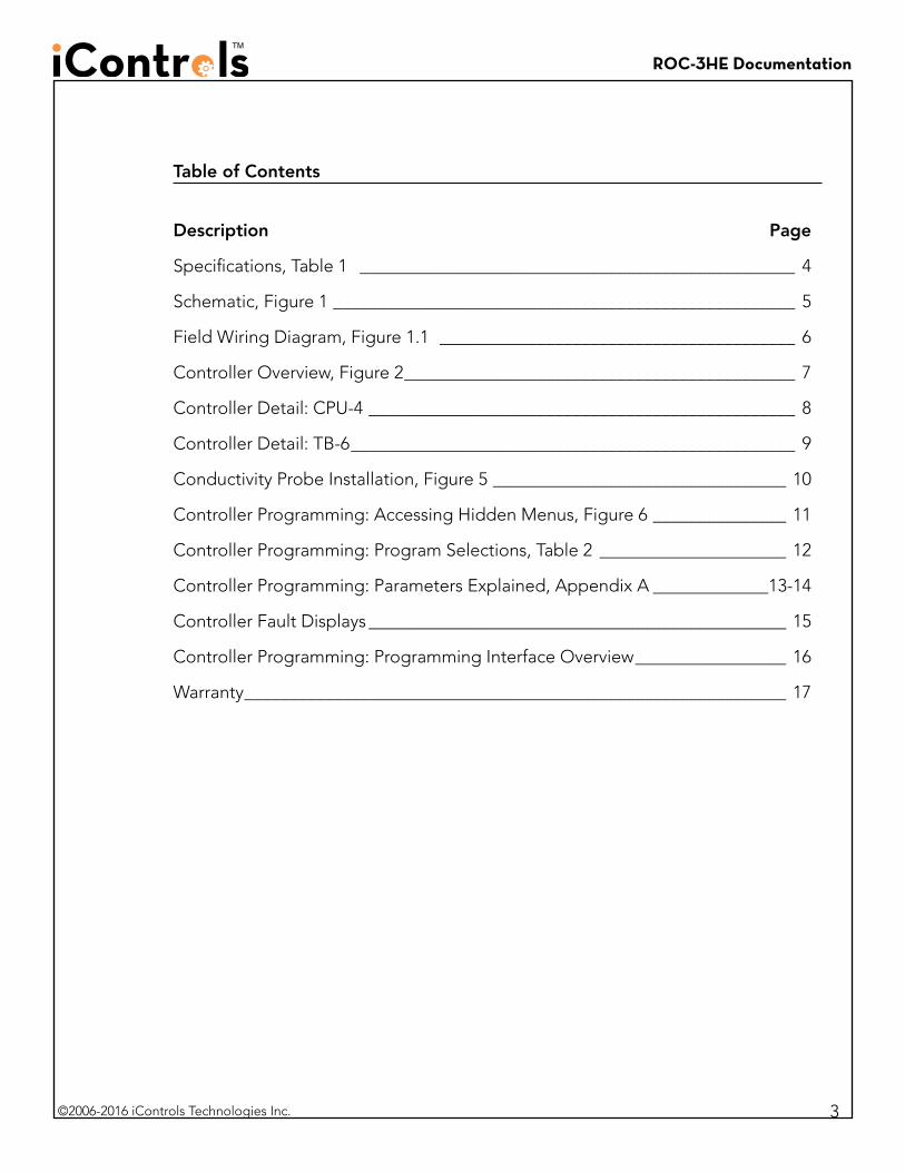
Table of Contents
Description Page
Specifications, Table 1 _________________________________________________ 4
Schematic, Figure 1 ____________________________________________________ 5
Field Wiring Diagram, Figure 1.1 ________________________________________ 6
Controller Overview, Figure 2 ____________________________________________ 7
Controller Detail: CPU-4 ________________________________________________ 8
Controller Detail: TB-6 __________________________________________________ 9
Conductivity Probe Installation, Figure 5 _________________________________ 10
Controller Programming: Accessing Hidden Menus, Figure 6 _______________ 11
Controller Programming: Program Selections, Table 2 _____________________ 12
Controller Programming: Parameters Explained, Appendix A _____________13-14
Controller Fault Displays _______________________________________________ 15
Controller Programming: Programming Interface Overview _________________ 16
Warranty _____________________________________________________________ 17
3
ROC-3HE Documentation
©2006-2016 iControls Technologies Inc.
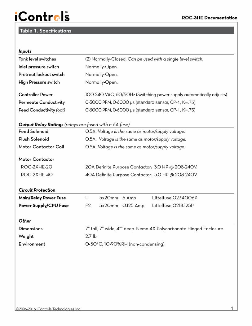
Inputs
Tank level switches (2) Normally-Closed. Can be used with a single level switch.
Inlet pressure switch Normally-Open.
Pretreat lockout switch Normally-Open.
High Pressure switch Normally-Open.
Controller Power 100-240 VAC, 60/50Hz (Switching power supply automatically adjusts)
Permeate Conductivity 0-3000 PPM, 0-6000 µs (standard sensor, CP-1, K=.75)
Feed Conductivity (opt) 0-3000 PPM, 0-6000 µs (standard sensor, CP-1, K=.75)
Output Relay Ratings (relays are fused with a 6A fuse)Feed Solenoid 0.5A. Voltage is the same as motor/supply voltage.
Flush Solenoid 0.5A. Voltage is the same as motor/supply voltage.
Motor Contactor Coil 0.5A. Voltage is the same as motor/supply voltage.
Motor Contactor
ROC-2XHE-20 20A Definite Purpose Contactor: 3.0 HP @ 208-240V.
ROC-2XHE-40 40A Definite Purpose Contactor: 5.0 HP @ 208-240V.
Circuit Protection
Main/Relay Power Fuse F1 5x20mm 6 Amp Littelfuse 0234006P
Power Supply/CPU Fuse F2 5x20mm 0.125 Amp Littelfuse 0218.125P
Other
Dimensions 7” tall, 7” wide, 4”” deep. Nema 4X Polycarbonate Hinged Enclosure.
Weight 2.7 lb.
Environment 0-50°C, 10-90%RH (non-condensing)
Table 1. Specifications
4
ROC-3HE Documentation
©2006-2016 iControls Technologies Inc.
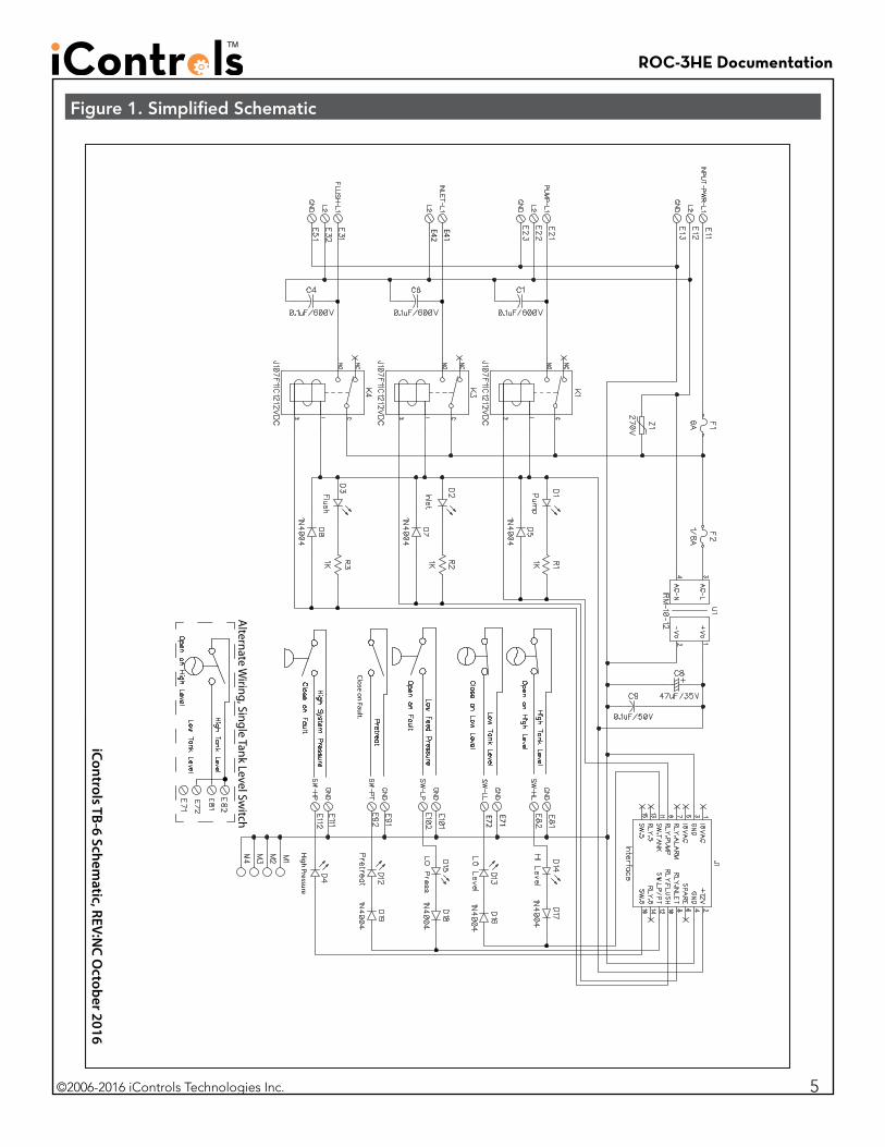
Figure 1. Simplified Schematic
High Pressure
E71
E72
E41
E42
iControls TB-6 Schematic, REV:N
C October 2016
Close on Fault.
Alternate W
iring, Single Tank Level Switch
5
ROC-3HE Documentation
©2006-2016 iControls Technologies Inc.
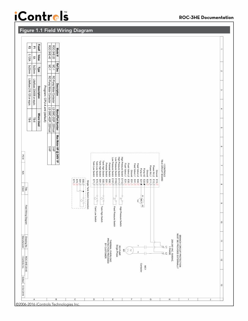
Figure 1.1 Field Wiring Diagram
Contactor
MC
1
208-240 VA
C, 50/60H
Z, 1 P
HA
SE
A1
A2
Coil
MC
1
Ref DesMC-1
DescriptionRO Pump Motor Contactor
Manuf/Part Num
berLS GMC-202P, 220Vcoil
6ALittelfuse 234006 or equiv.
A
12
34
56
78
910
1112
13
B C D E F G H I J
Edited
6 Oct 2016
Field Wiring D
iagramTitle
Client
RO
C-3H
E-20-40
Draw
ing No
Manufacturer
I Controls Inc.
PO
#N
/A
Fuse#Value
Where Used
Type
5x20mmDescription
TB-60.125A
Littelfuse 218.125 or equiv.5x20mm
TB-6F1F2
BR
AN
CH
CIR
CU
IT PR
OTE
CTIO
N
MU
ST B
E P
RO
VID
ED
EX
TER
NA
LLY
Program
: CP
U-4.xm
l (default)
L1L2
1
2
RO
PU
MP
, S
ingle Phase
M1
THE
RM
AL O
VE
RLO
AD
P
RO
TEC
TION
PR
OV
IDE
D
BY
CU
STO
ME
R
High P
ressure Sw
itch
E13
E11
E12
E22
E41
E42
E23
E32
E31
E102
E101
E91
E82
E92
E81
E71
E112
E72
E111
I CO
NTR
OLS
TB-6 C
IRC
UIT B
OA
RD
Pow
er IN L1
Pow
er IN L2
Ground
Feed Valve L1
Flush Valve L2
Flush Valve L1
Pum
p A2
Feed Valve L2
Pum
p A1
Low P
ressure Sw
itchLow
Pressure S
witch
Pretreat S
witch
Pretreat S
witch
Tank High S
witch
Tank High S
witch
Tank Low S
witch
Tank Low S
witch
High P
ressure Sw
itchH
igh Pressure S
witch
Tank High S
witch
Tank Low S
witch
Feed Pressure S
witch
Single Tank S
witch C
onnection
E81
E82
E72
E71
E21
Ground
E51
Ground
Model #
ROC-3HE-20MC-1
RO Pump Motor ContactorLS GMC-402P, 220Vcoil
ROC-3HE-40
Max M
otor HP @ 240V 1P
3 HP5 HP
ROC-3HE Documentation
©2006-2016 iControls Technologies Inc.
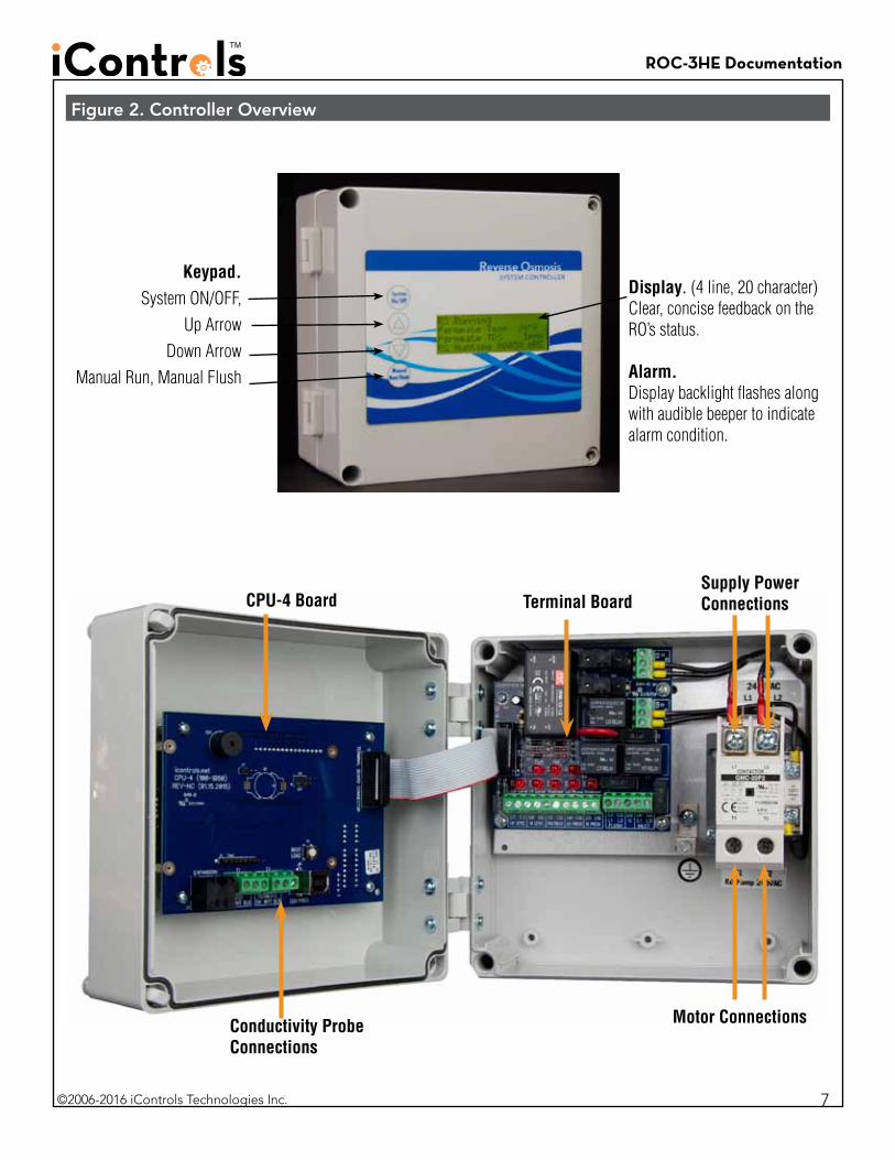
Display. (4 line, 20 character)Clear, concise feedback on the RO’s status.
Alarm.Display backlight flashes along with audible beeper to indicate alarm condition.
Keypad. System ON/OFF,
Up ArrowDown Arrow
Manual Run, Manual Flush
CPU-4 Board
Conductivity Probe Connections
Terminal Board
Figure 2. Controller Overview
7
Motor Connections
Supply Power Connections
ROC-3HE Documentation
©2006-2016 iControls Technologies Inc.
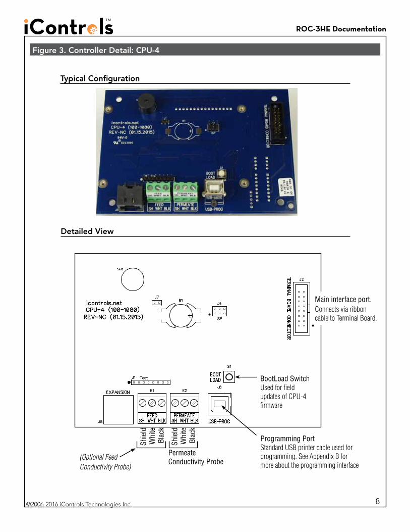
Figure 3. Controller Detail: CPU-4
Shie
ldW
hite
Blac
k
PermeateConductivity Probe
Programming PortStandard USB printer cable used for programming. See Appendix B for more about the programming interface
Shie
ldW
hite
Blac
k
(Optional Feed Conductivity Probe)
Main interface port. Connects via ribbon cable to Terminal Board.
Typical Configuration
Detailed View
BootLoad SwitchUsed for field updates of CPU-4 firmware
8
ROC-3HE Documentation
©2006-2016 iControls Technologies Inc.
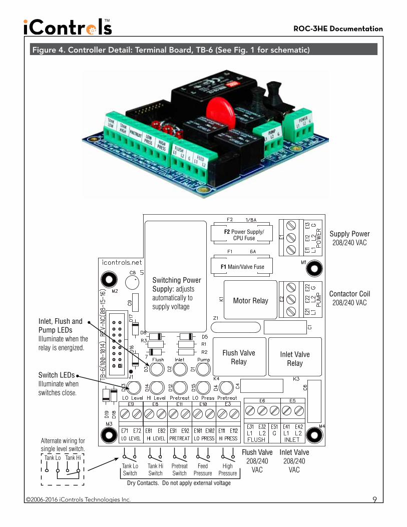
F2 Power Supply/CPU Fuse
F1 Main/Valve Fuse
Contactor Coil 208/240 VAC
Supply Power208/240 VAC
Flush Valve 208/240
VAC
Inlet Valve 208/240
VACFeed Pressure
Pretreat Switch
Tank Lo Switch
Tank Hi Switch
Switching Power Supply: adjusts automatically to supply voltage
Motor Relay
Dry Contacts. Do not apply external voltage
Alternate wiring for single level switch.
Tank Lo Tank Hi
Figure 4. Controller Detail: Terminal Board, TB-6 (See Fig. 1 for schematic)
Inlet Valve Relay
Flush Valve Relay
Switch LEDsIlluminate when switches close.
Inlet, Flush and Pump LEDsIlluminate when the relay is energized.
High Pressure
9
ROC-3HE Documentation
©2006-2016 iControls Technologies Inc.
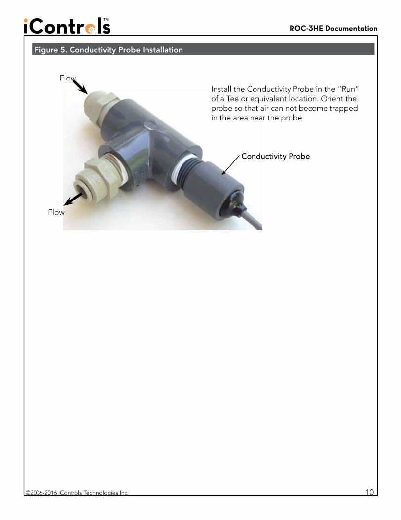
Figure 5. Conductivity Probe Installation
Install the Conductivity Probe in the “Run” of a Tee or equivalent location. Orient the probe so that air can not become trapped in the area near the probe.
Flow
Flow
Conductivity Probe
10
ROC-3HE Documentation
©2006-2016 iControls Technologies Inc.
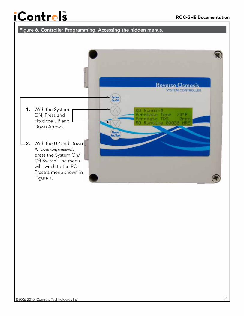
Figure 6. Controller Programming. Accessing the hidden menus.
1. With the System ON, Press and Hold the UP and Down Arrows.
2. With the UP and Down Arrows depressed, press the System On/Off Switch. The menu will switch to the RO Presets menu shown in Figure 7.
11
ROC-3HE Documentation
©2006-2016 iControls Technologies Inc.
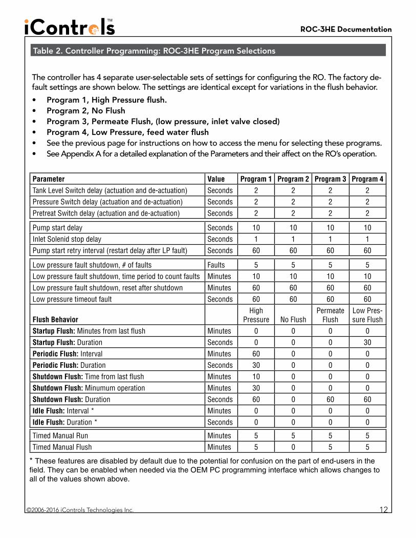
The controller has 4 separate user-selectable sets of settings for configuring the RO. The factory de-fault settings are shown below. The settings are identical except for variations in the flush behavior.• Program 1, High Pressure flush.• Program 2, No Flush• Program 3, Permeate Flush, (low pressure, inlet valve closed)• Program 4, Low Pressure, feed water flush• See the previous page for instructions on how to access the menu for selecting these programs. • See Appendix A for a detailed explanation of the Parameters and their affect on the RO’s operation.
Table 2. Controller Programming: ROC-3HE Program Selections
12
Parameter Value Program 1 Program 2 Program 3 Program 4Tank Level Switch delay (actuation and de-actuation) Seconds 2 2 2 2Pressure Switch delay (actuation and de-actuation) Seconds 2 2 2 2Pretreat Switch delay (actuation and de-actuation) Seconds 2 2 2 2
Pump start delay Seconds 10 10 10 10Inlet Solenid stop delay Seconds 1 1 1 1Pump start retry interval (restart delay after LP fault) Seconds 60 60 60 60
Low pressure fault shutdown, # of faults Faults 5 5 5 5Low pressure fault shutdown, time period to count faults Minutes 10 10 10 10Low pressure fault shutdown, reset after shutdown Minutes 60 60 60 60Low pressure timeout fault Seconds 60 60 60 60
Flush BehaviorHigh
Pressure No FlushPermeate
FlushLow Pres-sure Flush
Startup Flush: Minutes from last flush Minutes 0 0 0 0Startup Flush: Duration Seconds 0 0 0 30Periodic Flush: Interval Minutes 60 0 0 0Periodic Flush: Duration Seconds 30 0 0 0Shutdown Flush: Time from last flush Minutes 10 0 0 0Shutdown Flush: Minumum operation Minutes 30 0 0 0Shutdown Flush: Duration Seconds 60 0 60 60Idle Flush: Interval * Minutes 0 0 0 0Idle Flush: Duration * Seconds 0 0 0 0
Timed Manual Run Minutes 5 5 5 5Timed Manual Flush Minutes 5 0 5 5
* These features are disabled by default due to the potential for confusion on the part of end-users in the field. They can be enabled when needed via the OEM PC programming interface which allows changes to all of the values shown above.

ROC-3HE Documentation
©2006-2016 iControls Technologies Inc. 13
Parameter Value Range ExampleInput Switch BehaviorsTank Level Switch delay (actuation and de-actuation) Seconds 2.0
This specifies the time that the tank switch must be closed or open before the controller accepts it as a valid condi-tion. The function is to prevent nuisance tripping of the RO especially in small tanks or turbulent tanks
Pressure Switch delay (actuation and de-actuation) Seconds 3This specifies the time that the pressure switch must be closed or open before the controller accepts it as a valid condition. Since pressure switches usually have built-in hysteresis this value is set at 0.
Pretreat Switch delay (actuation and de-actuation) Seconds 2This is the time that the pretreat switch must be OPEN before the controller accepts it as a valid condition.
Pump/Inlet Solenoid BehaviorsPump start delay Seconds 10
On RO start-up, after the tank switch opens, the inlet solenoid valve is energized. When the inlet pressure switch closes this begins the “Pump start delay”. If the pressure switch remains closed, the pump will start after 10 sec-onds.
Inlet Solenid stop delay Seconds 1This value sets the delay for the inlet solenoid valve to be deenergized following the deenrgizing of the motor on RO shut down. The purpose is to prevent the pump from operating against a closed suction as the pump spins down.
Low Inlet Pressure BehaviorsPump start retry interval (restart delay after LP fault) Seconds 60
When the inlet pressure swith opens, the controller deenergizes the motor and the inlet solenoid valve remains open. The controller will continure to monitor the inlet pressure switch. After the switch is closed for the duration of the “Pump start retry interval” the motor is reenergized.
Low pressure fault shutdown, # of faults Faults 5Low pressure fault shutdown, time period to count faults Minutes 10Low pressure fault shutdown, reset after shutdown Minutes 60
These three values work together to determine how the RO handles Low Pressure conditions. The first two values, “# of faults” and “time period to count faults”, sets the limit for the number of low fault conditions over time that are required to place the RO in “Low Pressure Fault Shutdown”. The third value sets the duration of the “Low Pressure Fault Shutdown” which is the period that the RO will remain idle before trying to restart. The purpose of the Low Pressure Fault Shutdown is to prevent an RO from turning OFF/ON repeatedly without any limit.
Low pressure timeout fault Seconds 60If the inlet valve is open, but the pressure isn’t sufficient to close the inlet pressure switch, the RO would run indefi-nitely on line pressure. This value sets the time limit for the RO to operate with the inlet valve open with Low Pres-sure as indicated by an Open inlet pressure switch before a Low Pressure Fault is added to the counter above
Appendix A. Controller Programming: Parameters Explained
ROC-3HE Documentation
©2006-2016 iControls Technologies Inc. 14
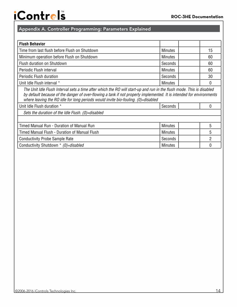
Flush BehaviorTime from last flush before Flush on Shutdown Minutes 15Minimum operation before Flush on Shutdown Minutes 60Flush duration on Shutdown Seconds 60Periodic Flush interval Minutes 60Periodic Flush duration Seconds 30Unit Idle Flush interval * Minutes 0
The Unit Idle Flush Interval sets a time after which the RO will start-up and run in the flush mode. This is disabled by default because of the danger of over-flowing a tank if not properly implemented. It is intended for environments where leaving the RO idle for long periods would invite bio-fouling. (0)=disabled
Unit Idle Flush duration * Seconds 0Sets the duration of the Idle Flush. (0)=disabled
Timed Manual Run - Duration of Manual Run Minutes 5Timed Manual Flush - Duration of Manual Flush Minutes 5Conductivity Probe Sample Rate Seconds 2Conductivity Shutdown * (0)=disabled Minutes 0
Appendix A. Controller Programming: Parameters Explained
ROC-3HE Documentation
©2006-2016 iControls Technologies Inc.
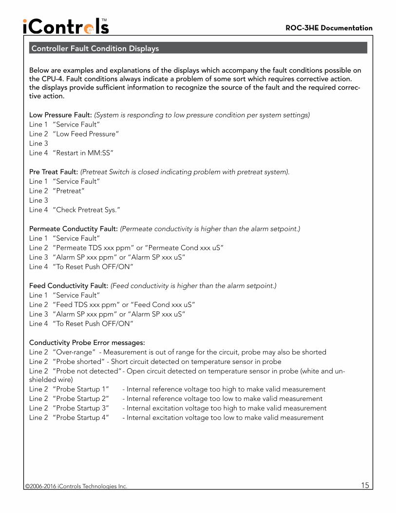
Below are examples and explanations of the displays which accompany the fault conditions possible on the CPU-4. Fault conditions always indicate a problem of some sort which requires corrective action. the displays provide sufficient information to recognize the source of the fault and the required correc-tive action.
Low Pressure Fault: (System is responding to low pressure condition per system settings)Line 1 “Service Fault”Line 2 “Low Feed Pressure”Line 3 Line 4 “Restart in MM:SS”
Pre Treat Fault: (Pretreat Switch is closed indicating problem with pretreat system).Line 1 “Service Fault”Line 2 “Pretreat”Line 3 Line 4 “Check Pretreat Sys.”
Permeate Conductity Fault: (Permeate conductivity is higher than the alarm setpoint.)Line 1 “Service Fault”Line 2 “Permeate TDS xxx ppm” or “Permeate Cond xxx uS”Line 3 “Alarm SP xxx ppm” or “Alarm SP xxx uS”Line 4 “To Reset Push OFF/ON”
Feed Conductivity Fault: (Feed conductivity is higher than the alarm setpoint.)Line 1 “Service Fault”Line 2 “Feed TDS xxx ppm” or “Feed Cond xxx uS”Line 3 “Alarm SP xxx ppm” or “Alarm SP xxx uS”Line 4 “To Reset Push OFF/ON”
Conductivity Probe Error messages:Line 2 “Over-range” - Measurement is out of range for the circuit, probe may also be shortedLine 2 “Probe shorted” - Short circuit detected on temperature sensor in probeLine 2 “Probe not detected” - Open circuit detected on temperature sensor in probe (white and un-shielded wire)Line 2 “Probe Startup 1” - Internal reference voltage too high to make valid measurementLine 2 “Probe Startup 2” - Internal reference voltage too low to make valid measurementLine 2 “Probe Startup 3” - Internal excitation voltage too high to make valid measurementLine 2 “Probe Startup 4” - Internal excitation voltage too low to make valid measurement
Controller Fault Condition Displays
15
ROC-3HE Documentation
©2006-2016 iControls Technologies Inc. 16
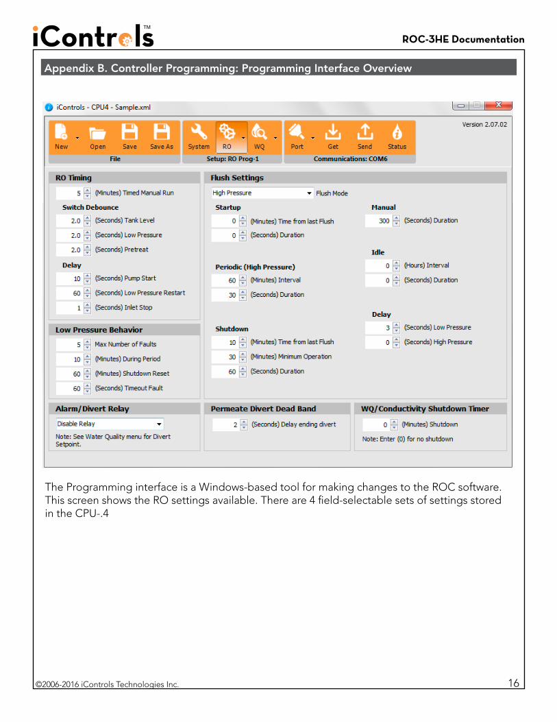
Appendix B. Controller Programming: Programming Interface Overview
The Programming interface is a Windows-based tool for making changes to the ROC software. This screen shows the RO settings available. There are 4 field-selectable sets of settings stored in the CPU-.4
ROC-3HE Documentation
©2006-2016 iControls Technologies Inc.
Appendix C. Warranty
iControls Limited Warranty
What the warranty covers:iControls warrants the ROC-3HE to be free from defects in materials and workmanship during the war-ranty period. If a product proves to be defective during the warranty period, iControls will at is sole option repair or replace the product with a like product. Replacement product or parts may include remanufactured or refurbished parts or components.
How long the warranty is effective:The ROC-3HE is warranted for one (1) year for parts and labor from the date of the first consumer pur-chase or 15 months from ship date, whichever comes first.
What the warranty does not cover: 1. Damage, deterioration or malfunction resulting from: a. Accident misuse, neglect, fire, water lightning or other acts of nature, unauthorized product
modification or failure to follow instructions supplied with the product. b. Repair or attempted repair by anyone not authorized by iControls c. Any damage of the product due to shipment. d. Causes external to the product such as electric power fluctuations. e. Use of supplies or parts not meeting iControls’ specifications. f. Normal wear and tear. g. Any other cause which does not relate to a product defect. 2. Transportation costs necessary to obtain service under this warranty. 3. Labor other than factory labor.
How to get service: 1. To obtain warranty service, contact iControls for a Return Material Authorization (RMA). 2. You will be required to provide: a. Your name and address b. A description of the problem 3. Package the controller carefully for shipment and return it to iControls, freight prepaid.
Limitation of implied warranties:There are no warranties, expressed or implied, which extend beyond the description contained herein including the implied warranty of merchantablility and fitness for a particular purpose.
Exclusion of damages:iControls’ liability is limited to the cost of repair or replacement of the product. iControls shall not be liable for: 1. Damage to other property caused by any defects in the product, damages based upon incon-
venience, loss of use of the product, loss of time, loss of profits, loss of business opportunity, loss of goodwill, interference with business relationships or other commercial loss, even if advised of the possibility or such damages.
2. Any other damages, whether incidental, consequential or otherwise. 3. Any claim against the customer by any other party.
Effect of state law:This warranty gives you specific legal rights, and you may also have other rights which vary from state to state. Some states do not allow limitations on implied warranties and/or do not allow the exclusion of incidental or consequential damages, so the above limitations and exclusions may not apply to you.
17