robust statcom voltage controller design using loop-shaping
TRANSCRIPT

Electric Power Systems Research 68 (2004) 61�/74
www.elsevier.com/locate/epsr
Robust STATCOM voltage controller design using loop-shapingtechnique
A.H.M.A. Rahim *, M.F. Kandlawala
Department of Electrical Engineering, KF University of Petroleum and Minerals (KFUPM), P.O. Box 349, Dhahran 31261, Saudi Arabia
Received 22 July 2002; received in revised form 9 January 2003; accepted 5 May 2003
Abstract
Static synchronous compensator (STATCOM) is a shunt-connected converter, which can affect rapid control of reactive flow in
the transmission line by controlling the generated a.c. voltage. This article presents a robust STATCOM voltage controller design
for power system damping. The method of multiplicative uncertainty has been employed to model the variations of the operating
points. The design is carried out applying robustness criteria for stability and performance. A loop-shaping technique has been
employed to select a suitable open-loop transfer function, from which the robust controller function is constructed. The controller
was tested for a number of disturbances including three-phase fault. The damping provided by the robust controller was compared
with a fixed-parameter PID controller, whose gains were calculated through a pole-placement technique. It has been observed that
the PID control is ineffective at operating points other than nominal. The robust design has been demonstrated to provide extremely
good damping characteristics over a range of operating conditions.
# 2003 Elsevier B.V. All rights reserved.
Keywords: STATCOM; Shunt-connected FACTS; Damping control; Robust control; Loop-shaping technique; Pole-placement
1. Introduction
Fast acting solid state, thyristor switches of the
FACTS devices are known to improve both the
transient as well as dynamic performance of a power
system [1]. Fixed or mechanically switched capacitors
and reactors have long been employed to increase the
steady-state power transmission by controlling the
voltage profile along the lines. Controllable synchro-
nous voltage sources known as static compensators are a
recent introduction in power system for dynamic
compensation and for real time control of power flow.
The static synchronous compensator (STATCOM)
provides shunt compensation in a way similar to the
static var compensators (SVC), but utilizes a voltage
source converter rather than shunt capacitors and
reactors [2,3]. STATCOM is an active device, which
can control voltage magnitude and, to a small extent,
* Corresponding author. Tel.: �/966-3-860-2277; fax: �/966-3-860-
3535.
E-mail address: [email protected] (A.H.M.A. Rahim).
0378-7796/03/$ - see front matter # 2003 Elsevier B.V. All rights reserved.
doi:10.1016/S0378-7796(03)00153-6
the phase angle in a very short time and, therefore, has
the ability to improve the system damping as well as
voltage profiles of the system. It has been reported that
STATCOM can offer a number of performance advan-
tages for reactive power control applications over the
conventional SVC because of its greater reactive current
output at depressed voltage, faster response, better
control stability, lower harmonics and smaller size, etc.
[4]
The STATCOM is normally designed to provide fast
voltage control and to enhance damping of inter-area
oscillations. A typical method to meet these require-
ments is to superimpose a supplementary damping
controller upon the automatic voltage control loop [4].
Several recent articles have reported that STATCOM
can provide damping to a power system [5,7�/10]. They
have also been shown to improve torsional oscillations
in a power system [11].
Two basic controls are implemented in a STATCOM.
The first is the a.c. voltage regulation of the power
system, which is realized by controlling the reactive
power interchange between the STATCOM and the
power system. The other is the control of the d.c. voltage

Fig. 1. The single machine infinite bus power system with STATCOM.
A.H.M.A. Rahim, M.F. Kandlawala / Electric Power Systems Research 68 (2004) 61�/7462
across the capacitor, through which the active power
injection from the STATCOM to the power system is
controlled [5,6]. PI controllers have been found to
provide stabilizing controls when the a.c. and d.c.regulators were designed independently. However, joint
operations of the two have been reported to lead to
system instability because of the interaction of the two
controllers [6,8,12]. While superimposing the damping
controller on the a.c. regulator can circumvent the
negative interaction problem, the fixed parameter PI
controllers have been found invalid, or even to provide
negative damping for certain system parameters andloading conditions [4]. Application of control that
performed over a range of operating conditions has
also been reported in recent times. Farasangi and Chen
proposed a robust controller for SVC and STATCOM
devices using H� techniques and direct feedback
linearization, respectively [13,14]. These designs are
often complicated restricting their realization. A robust
design for a current-controlled STATCOM was pre-sented in [15] considering a simplified reduced order
power system model.
This article presents a simple graphical loop-shaping
technique for designing a robust damping controller for
a STATCOM. A detailed power system model was
considered. Two controls were identified with the
voltage controlled STATCOM*/the voltage magnitude
and its phase angle. Robust stability and performancemeasures were employed to derive a constant-coefficient
robust voltage magnitude controller function in the s-
domain. The proposed controller was tested over a
range of operating conditions for a number of dis-
turbances and was found to provide good damping
characteristics.
2. The system model
A single machine infinite bus system with a STAT-
COM installed at the mid-point of the transmission line
is shown in Fig. 1. The system consists of a step down
transformer (SDT) with a leakage reactance XSDT, a
three phase GTO-based voltage source converter, and a
d.c. capacitor. The STATCOM is modeled as a voltage
sourced converter (VSC) behind a SDT. The VSCgenerates a controllable a.c. voltage source V0(t)�/V0
sin(vt�/c) behind the leakage reactance. Depending on
the magnitude of V0, current ILo can be made to lead or
lag the bus voltage VL. Thus the STATCOM can be
made to supply or absorb reactive power by controlling
the voltage magnitude of the VSC. Generally, the
STATCOM voltage is in phase with the bus voltage.
However, some active power control may be possiblethrough a limited control of phase angle c . This would
necessitate a power source behind the capacitor voltage.
The dynamic relation between the capacitor voltage and
current in the STATCOM circuit are expressed as [6,8],
dVdc
dt�
Idc
Cdc
�m
Cdc
(ILod cos c�ILoq sin c) (1)
where, ILod and ILoq are the direct and quadrature axes
components of STATCOM current ILo. The output
voltage phasor is
V 0�mVdc�c (2)
The magnitude of the STATCOM voltage depends on
m , which is a product of the a.c./d.c. voltage ratio and
the modulation ratio defined by the PWM.The dynamics of the generator and the excitation
system are expressed through a fourth order model
given as
d�v�v0
v��1
M[Pm�Pe�D(v�v0)]
e?q�1
T ?do
[Efd�eq]
Efd��1
TA
(Efd�Efdo)�KA
TA
(Vto�Vt)
(3)
A list of symbols is given in the Appendix A. The
expressions for the power output, terminal voltage, and
the d�/q axes currents in the transmission line and
STATCOM, respectively, are

A.H.M.A. Rahim, M.F. Kandlawala / Electric Power Systems Research 68 (2004) 61�/74 63
Pe�VdItLd�VqItLq�e?qItLd�(xd�x?d)ItLq
Vt�ffiffiffiffiffiffiffiffiffiffiffiffiffiffiffiffiffiffiV 2
d �V 2q
q�
ffiffiffiffiffiffiffiffiffiffiffiffiffiffiffiffiffiffiffiffiffiffiffiffiffiffiffiffiffiffiffiffiffiffiffiffiffiffiffiffiffiffiffiffi(e?q�x?dItLd)2�x?qI2
tLq
q
ItLd�
�1 �
XLB
XSDT
�e?q �
XLB
XSDT
mVdc sin c� Vb cos d
XtL � XLB �XTL
XLB
��
1 �XLB
XSDT
�x?d
ItLq�
XLB
XSDT
mVdc cos c� Vb sin d
XtL � XLB �XTL
XLB
��
1 �XLB
XSDT
�x?q
ILod�e?q
XSDT
�(x?d � XtL)ItLq
XSDT
�mVdc sin c
XSDT
ILoq�mVdc cos c
XSDT
�(x?d � XtL)ItLq
XSDT
Deq�De?q�(xd�x?d)DItLd
(4)
For a choice of the state and control vectors as
[Dd Dv De?q DEfd DVdc]T and [Dm Dc]T; respec-
tively, the nonlinear state model Eqs. (1) and (4) for the
generator*/STATCOM system can be expressed as [8]
x� f (x; u) (5)
The linearized state model for small perturbationaround a nominal operating condition is expressed as
x�Ax�Bu
y�Hx(6)
Here, H represents the relation between the perturbed
state vector x and the chosen output y . Fig. 2 shows the
Fig. 2. The linearized sys
block diagram for the linearized system. The derivations
for the linearized system are included in Appendix B.
3. Robust control design
The damping control problem for the nonlinear
power system model is stated as: given the set of
equations (5), design a controller whose output u will
stabilize the system following a perturbation. Since there
is no general method of designing a stabilizing controller
for the nonlinear system, one way would be to perform
the control design for a linearized system; the lineariza-
tion being carried out around a nominal operatingcondition. If the controller designed is ‘robust’ enough
to perform well for the other operating conditions in the
vicinity, the design objectives are met.
The changes in operating points of the nonlinear
system can be considered as perturbations in the
coefficients of the linearized system matrices. These
perturbations are modeled as multiplicative uncertain-
ties and robust design procedure is applied to theperturbed linear systems. This section gives a brief
theory of the uncertainty model, the robust stability
criterion, and a graphical design technique termed loop
shaping, which is employed to design the robust
controller. Finally, the algorithm for the control design
is presented.
3.1. Uncertainty modeling
Suppose that a plant having a nominal transfer
function P belongs to a bounded set of transfer
functions P. Consider that the perturbed transfer
tem block diagram.

A.H.M.A. Rahim, M.F. Kandlawala / Electric Power Systems Research 68 (2004) 61�/7464
function, resulting from the variations in operatingconditions, can be expressed in the form [16]
P�(1�VW2)P (7)
Here, W2 is a fixed stable transfer function, also called
the weight, and V is a variable transfer function
satisfying jjVjj�B/1. The infinity norm (�-norm) of a
function is the least upper bound of its absolute value,
also written as jjVjj��/supv jV(jv )j, is the largest value
of gain on a Bode magnitude plot.
The plant transfer function is obtained from Eq. (6) as
P�/H [sI�/A]�1B. The matrices A and B are operatingpoint dependent through the coefficients K1, K2, etc.
given in Appendix B. The uncertainties, which are the
variations of system operating conditions, are thus
modeled through P in Eq. (7).
In the multiplicative uncertainty model Eq. (7), VW2
is the normalized plant perturbation away from 1. If
jjVjj�B/1, then
jP(jv)
P(jv)�1j5 jW2(jvjj; �v (8)
So, jW2(jv )j provides the uncertainty profile, and in
the frequency plane is the upper boundary of all the
normalized plant transfer functions away from 1.
3.2. Robust stability and performance
Consider a multi-input control system given in Fig. 3.
A controller C provides stability if it provides internal
stability for every plant in the uncertainty set P. If L
denotes the open-loop transfer function (L�/PC ), thenthe sensitivity function S is written as
S�1
1 � L(9)
The complimentary sensitivity function or the input�/
output transfer function is
T �1�S�PC
1 � PC(10)
For a multiplicative perturbation model, robuststability condition is met if and only if jjW2T jj8B/1
[16,17]. This implies that
Fig. 3. Unity feedback plant with controller.
jW2(jv)L(jv)
1 � L(jv) jB1; for all v (11)
or,
jV(jv)W2(jv)L(jv)jBj1�L(jv)j;for all v; and ½½V½½8B1:
(12)
The block diagram of a typical perturbed system,ignoring all inputs, is shown in Fig. 4(a). The transfer
function from output of V to the input of V equals �/
W2T . The properties of the block diagram can be
reduced to those of the configuration given in Fig.
4(b) [17,18].
The maximum loop gain jj�/W2T jj8 is less than 1 for
all allowable V if and only if the small gain condition
jjW2T jj8B/1 holds. The nominal performance condi-tion for an internally stable system is given as
jjW1S jj8B/1, where W1 is a real-rational, stable, mini-
mum phase transfer function, also called a weighting
function. If P is perturbed to P�(1�VW2)P; S is
perturbed to
S�1
1 � (1 � VW2L)�
S
1 � VW2T(13)
The robust performance condition should thereforebe
kW2Tk8B1; and k W1S
1 � VW2T kB1; �½½V½½B1: (14)
Combining all the above, it can be shown that a
necessary and a sufficient condition for robust stability
and performance is [16]
kjW1Sj�jW2T jk8B1 (15)
3.3. The loop-shaping technique
Loop shaping is a graphical procedure to design a
proper controller C satisfying robust stability and
performance criteria given above. The basic idea of the
method is to construct the loop transfer function L tosatisfy the robust performance criterion approximately,
and then to obtain the controller from the relationship
C�/L /P . Internal stability of the plants and properness
of C constitute the constraints of the method. Condition
on L is such that PC should not have any pole zero
cancellation.
A necessary condition for robustness is that either or
both jW1j and jW2j must be less than 1 [16]. If we select amonotonically decreasing W1 satisfying the other con-
straints on it, it can be shown that at low frequency the
open-loop transfer function L should satisfy

Fig. 4. (a) Feedback loop with uncertainty representation; (b) feedback loop in standard reduced form.
A.H.M.A. Rahim, M.F. Kandlawala / Electric Power Systems Research 68 (2004) 61�/74 65
½L½�jW1j
1 � jW2j(16)
while, for high frequency
½L½B1 � jW1jjW2j
:1
jW2j(17)
At high frequency jL j should roll-off at least as
quickly as jP j does. This ensures properness of C . The
general features of open-loop transfer function is that
the gain at low frequency should be large enough, andjL j should not drop-off too quickly near the crossover
frequency resulting into internal instability.
3.4. The algorithm
The algorithm to generate a control transfer function
P�0:2104s2(s � 100:827)(s � 0:234)
(s � 99:1725)(s � 1:0945)(s � 0:0476)(s2 � 0:6754s � 21:6344)(18)
C so that robust stability and robust performance
conditions are met involves the following steps.
1) Obtain the dB-magnitude plot for the nominal as
well as perturbed plant transfer functions.
2) Construct W2 satisfying constraint Eq. (8).
3) Select W1 as a monotonically decreasing, real,
rational and stable function.
4) Choose L such that it satisfies conditions Eqs. (16)
and (17). The transition at crossover frequency
should not be at a slope steeper than �/20 dB/
decade. Nominal internal stability is achieved if on a
Nyquist plot of L , the angle of L at crossover is
greater than 1808.5) Check for the nominal and robust performance
criteria given in Section 3.2.
6) Construct the controller transfer function from the
relation C�/L /P .7) Test for internal stability by direct simulation of the
closed-loop transfer function for pre-selected dis-
turbance or input.
8) Repeat steps 4 through 7 until satisfactory L and C
are obtained.
4. STATCOM voltage controller implementation
The robust controller design procedure starts by
arranging the system in the form shown in Fig. 3.
The plant output to be fed back to the controller C is
chosen to be the generator angular speed variation, Dv .
The nominal operating point for the design was
computed for a delivered power of 0.9 pu at unity
power factor. The system parameters are given in
Appendix C.
The nominal plant transfer function for the selected
operating point is computed as
Off-nominal power outputs between 0.4 and 1.4 pu and
power factor from 0.8 lagging to 0.8 leading were
considered. The dB-magnitude vs. frequency response
for the nominal and perturbed plants is shown in Fig. 5.
From Fig. 5, the quantity, ½P(jv)=P(jv)�1½ for each
perturbed plant is constructed and the uncertainty
profile is fitted to the following function,
W2(s)�0:9s2 � 15s � 27
s2 � 5s � 31(19)
A Butterworth filter satisfies all the properties for
W1(s ) and is written as
W1(s)�Kdf 2
c
s3 � 2s2fc � 2sf c2 � f 3
c
(20)
For Kd�/0.01 and fc�/0.1, and for a choice of open-
loop transfer function L as

Fig. 5. dB-magnitude plot for nominal and perturbed plant transfer functions.
Fig. 6. Loop-shaping plots relating W1, W2 and L .
A.H.M.A. Rahim, M.F. Kandlawala / Electric Power Systems Research 68 (2004) 61�/7466

Fig. 7. The nominal and robust performance criteria.
A.H.M.A. Rahim, M.F. Kandlawala / Electric Power Systems Research 68 (2004) 61�/74 67
L�5(s � 100:83)(s � 0:214309)(s � 1)(s � 0:001)
(s � 10)(s � 0:1)(s � 0:01)(s2 � 0:6754s � 21:6344)
(21)
gives the desired controller transfer function
C�27:7631(s � 1)(s � 1:094)(s � 0:0476)(s � 0:001)(s � 99:1725)
s2(s � 10)(s � 0:1)(s � 0:01)(22)
The dB-magnitude plots relating W1, W2 and L ,
which were employed to arrive at this controller, is
shown in Fig. 6. The open-loop function L is selected to
fit the bounds set by Eqs. (16) and (17). The plots for the
nominal and robust performance criteria are shown in
Fig. 7. While the nominal performance measure W1S is
well-satisfied, the combined robust stability and perfor-
mance measure has a small peak. This is because worst-
case, zero damping condition was considered in the
design.
Once the robust stability and performance criteria
plotted in Fig. 7 are met, the stability and performance
of the closed-loop system have to be checked by direct
simulation of the system dynamic equations. MATLAB
ODE routines were used for this purpose and the system
was disturbed by a 50% input torque pulse for 0.1 s.
Fine tuning on the controller parameters were per-
formed from observation of the transient response of the
system. Figs. 8�/10 show the variations of generator
angle, angular speed and STATCOM d.c. voltage
variations, respectively, for the nominal plant, with
and without control. Variation of the STATCOM d.c.
voltage is very small thus enabling it to control both the
reactive and real flow effectively (note, Vdco�/4 pu).The effectiveness of the robust design was tested for a
number of other operating conditions. Figs. 11 and 12
show the variations of generator rotor angle and the
STATCOM d.c. voltage variations for the following
four operating conditions: (a) 1.2-pu generator power
output, 0.98-pf lead, (b) 1-pu output, 0.95 pf lag, (c) 0.9-
pu output, unity pf and (d) 0.5-pu output, 0.95-pf lag.

Fig. 8. Rotor angle variation following 50% input torque pulse for 0.1 s with (a) proposed robust control; and (b) no control.
Fig. 9. Generator angular frequency variation corresponding to Fig. 8 with, (a) robust control; and (b) no control.
A.H.M.A. Rahim, M.F. Kandlawala / Electric Power Systems Research 68 (2004) 61�/7468

Fig. 10. D.C. capacitor voltage variation corresponding to the disturbance condition of Fig. 8 with, (a) robust control; and (b) no control.
Fig. 11. Generator angle variations following 50% input torque pulse for 0.1 s, for (a) 1.2 pu power output, (b) 1 pu output, (c) 0.9 pu output, and (d)
0.5 pu output.
A.H.M.A. Rahim, M.F. Kandlawala / Electric Power Systems Research 68 (2004) 61�/74 69

Fig. 12. D.C. capacitor voltage variations for the different load conditions corresponding to Fig. 11.
Fig. 13. Generator rotor angle variation following a three-phase fault on the remote bus for 0.1 s with, (a) 1.2 pu power output; (b) 1 pu output; (c)
0.9 pu output and; (d) 0.5 pu output.
A.H.M.A. Rahim, M.F. Kandlawala / Electric Power Systems Research 68 (2004) 61�/7470

Fig. 14. STATCOM bus voltage variations following the three-phase fault condition of Fig. 13.
A.H.M.A. Rahim, M.F. Kandlawala / Electric Power Systems Research 68 (2004) 61�/74 71
The disturbance considered in each case was a 50%
torque pulse on the generator shaft for 0.1-s duration. It
can be observed that the proposed controller is very
effective in providing damping for such varying load
conditions. Expectedly, the effectiveness of the control-ler will decrease as the point of operation moves further
and further away from the nominal value.
The robust controller designed was also tested con-
sidering large disturbances. The nonlinear system of
equations (5) was considered for this purpose. A three-
phase fault for 0.1-s duration was simulated on the
remote bus. The transient responses recorded for the
generator rotor angle and STATCOM bus voltagevariations for the four system operating conditions are
shown in Figs. 13 and 14, respectively. Results show that
the robust control damps both the electromechanical
and electrical transients vary effectively. The controller
can stabilize the unstable system for even longer fault
durations. The transient voltage variations, however, are
large in such cases.
5. Evaluation of the robust design
This section presents a comparison of the responses
obtained by the proposed H8-based robust controller
design with fixed parameter controllers. Optimum fixed
parameter controller may be designed using linear
regulator formulation, PID controller tuning based on
pole-placement technique, etc. These methods produce
optimum controller functions for linear systems de-
signed for specific operating points. We consider thepole-placement method to design the gains of a PID
controller in the following.
Consider a PID controller,
GPID(s)�KP�KI
s�KDs (23)
Here, KP, KI, KD are the gains in the proportional,
integral and derivative loops. Often a washout has to be
included in the controller to eliminate any unwanted
steady state signal. The controller transfer function then
takes the form
Gc(s)�sTw
1 � sTw
�KP�
KI
s�KDs
�(24)
where Tw is the washout time constant.
By assigning three poles of the compensated closed-
loop system the appropriate values of KP, KI and KD can
be determined. The location of the dominant eigenva-lues can be selected to provide the specified damping to
the system. For the choice of dominant eigenvalues at
�/39/j10, corresponding to the damping ratio of 0.287,
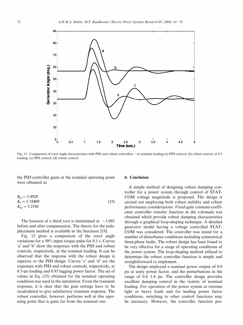
Fig. 15. Comparison of rotor angle characteristics with PID and robust controllers*/at nominal loading (a) PID control; (b) robust control; at 0.5
loading; (c) PID control; (d) robust control.
A.H.M.A. Rahim, M.F. Kandlawala / Electric Power Systems Research 68 (2004) 61�/7472
the PID controller gains at the nominal operating point
were obtained as
KP�5:4928
KI�2:18409
KD�3:2166
(25)
The location of a third root is maintained at �/1.091
before and after compensation. The theory for the pole-
placement method is available in the literature [19].Fig. 15 gives a comparison of the rotor angle
variations for a 50% input torque pulse for 0.1 s. Curves
‘a’ and ‘b’ show the responses with the PID and robust
controls, respectively, at the nominal loading. It can be
observed that the response with the robust design is
superior to the PID design. Curves ‘c’ and ‘d’ are the
responses with PID and robust controls, respectively, at
0.5-pu loading and 0.95 lagging power factor. The set of
values in Eq. (25) obtained for the nominal operating
condition was used in the simulation. From the transient
response, it is clear that the gain settings have to be
recalculated to give satisfactory transient response. The
robust controller, however, performs well at this oper-
ating point that is quite far from the nominal one.
6. Conclusion
A simple method of designing robust damping con-
troller for a power system through control of STAT-
COM voltage magnitude is proposed. The design is
carried out employing both robust stability and robust
performance considerations. Fixed-gain constant-coeffi-
cient controller transfer function in the s-domain was
obtained which provide robust damping characteristics
through a graphical loop-shaping technique. A detailed
generator model having a voltage controlled STAT-
COM was considered. The controller was tested for a
number of disturbance conditions including symmetrical
three-phase faults. The robust design has been found to
be very effective for a range of operating conditions of
the power system. The loop-shaping method utilized to
determine the robust controller function is simple and
straightforward to implement.
The design employed a nominal power output of 0.9
pu at unity power factor, and the perturbations in the
range of 0.4�/1.4 pu. The controller design provides
excellent damping control in the vicinity of nominal
loading. For operation of the power system at extreme
light or heavy loads and for leading power factor
conditions, switching to other control functions may
be necessary. However, the controller function pre-

A.H.M.A. Rahim, M.F. Kandlawala / Electric Power Systems Research 68 (2004) 61�/74 73
sented here will cover the normal loading ranges of the
system.
Acknowledgements
The authors wish to acknowledge the facilities pro-
vided at the King Fahd University of Petroleum and
Minerals, Dhahran, Saudi Arabia.
Appendix A: Nomenclature
XTL,
XLB
transmission line reactances
M , D
inertia and damping coefficients Vt generator terminal voltagePm, Pe
generator input and output powerCdc
d.c. capacitancec
phase angle of the mid-bus voltageeq ?, eq
internal voltage behind transient and syn-chronous reactances
Efd
generator field voltaged
generator rotor angle Tdo ? open circuit field time constantKA, TA
exciter gain and time constantsxd, xd’
direct axis synchronous and transient reac-tance
v0
base radian frequencyid, iq
armature currents along d�/q axesVd, Vq
armature voltage in d�/q axesVb, Vm
infinite bus and STATCOM bus voltagesAppendix B: The linearized system equations
Taking variations around the operating points, Eq.
(3) can be written as
Dd�v0Dv
Dv��1
M[�DPe�DDv]
De?q�1
T ?do
[�De?q�DEfd�(xd�x?d)DItLd]
DEfd��1
TA
(DEfd�KADVt)
DVdc�1
CDc
(ILod cos c0�ILoq sin c0)Dm
�m0(�ILod sin c0�ILoq cos c0)Dc��m0(cos c0 DILod�DILoq sin c0)
24
35
(A1)
Dv represents the per unit speed and is given as (v�/
v0)/v0. The perturbations of the non-state variables Eq.
(4) are
DPe�K1Dd�K2De?q�KpDcDVDc�KpeDm�KpcDcDeq�K4Dd�K3De?q�KqDcDVDc�KqeDm�KqcDcDVt�K5Dd�K6De?q�KvDcDVDc�KveDm�KvcDc
(A2)
The state matrix can be written as,
Dd:
Dv:
Deq?:
DEfd
:
DVdc
:
2666664
3777775�
0 vb 0 0 0
�K1
M�
D
M�
K2
M0 �
Kpdc
M
�K4
Tdo
00 �
K3
Tdo
0�
1
Tdo
0�
Kqdc
Tdo
0
�KAK5
TA
0 �KAK6
TA
�1
TA
�KAKvdc
TA
K7 0 K8 K9 0
26666666666664
37777777777775
�
DdDvDeq?DEfd
DVdc
266664
377775�
0 0
�Kpc
M�
KqC
M
�Kqc
Tdo
0�
KqC
Tdo
0
�KAKvC
TA
�KAKvC
TA
Kdc KdC
2666666666664
3777777777775
Dm
DC
� �
(A3)
Appendix C: The system parameters
All the quantities are in per unit, except as indicated.
H�/3.0 s, Tdo ?�/6.3 s, xd�/1.0, xd ?�/0.3, xq�/0.6,
D�/0; XTL�/0.3, XLB�/0.3, XSDT�/0.15, KA�/10,
TA�/0.05 s, Cdc�/1.0, m0�/0.25, c0�/46.528.Nominal plant operating conditions: Peo�/0.9, Vto�/
1.0, pf�/1.0.
References
[1] L. Gyugyi, Dynamic compensation of ac transmission lines by
solid-state synchronous voltage sources, IEEE Trans. Power
Delivery 9 (2) (1994) 904�/911.
[2] J. Machowski, Power System Dynamics and Stability, Wiley,
1997.
[3] N. Hingorani, L. Gyugi, Understanding FACTS, IEEE Press,
New York, 2000.
[4] C. Li, Q. Jiang, Z. Wang, D. Retzmann, Design of a rule based
controller for STATCOM, Proceedings of the 24th Annual
Conference of IEEE Ind. Electronic Society, IECon ’98, vol. 1,
1998, pp. 467�/472.
[5] H.F. Wang, F. Li, Design of STATCOM multivariable sampled
regulator, International Conference on Electric Utility Deregula-
tion and Power Technology 2000, City University, London, April,
2000.

A.H.M.A. Rahim, M.F. Kandlawala / Electric Power Systems Research 68 (2004) 61�/7474
[6] H. Wang, F. Li, Multivariable sampled regulators for the co-
coordinated control of STATCOM ac and dc voltage, IEE
Proc.*/Generation Transm. Distrib. 147 (2) (2000) 93�/98.
[7] K.R. Padiyar, A.L. Devi, Control and simulation of static
condenser, APEC 94*/Ninth Annual Applied Power Electronics
Conference and Exposition, vol. 1, no. 2, 1994, pp. 826�/831.
[8] H.F. Wang, Phillips-Heffron model of power systems installed
with STATCOM and applications, IEE Proc. Generation
Transm. Distrib. 146 (5) (1999) 521�/527.
[9] P. Rao, M.L. Crow, Z. Young, STATCOM control for power
system voltage control applications, IEEE Trans. Power Delivery
15 (2000) 1311�/1317.
[10] P.S. Sensarma, K.R. Padiyar, V. Ramnarayanan, Analysis and
performance evaluation of a distribution STATCOM for com-
pensating voltage fluctuation, IEEE Trans. Power Delivery 16
(2001) 259�/264.
[11] K.V. Patil, J. Senthil, J. Jiang, R.M. Mathur, Application of
STATCOM for damping torsional oscillations in series compen-
sated ac systems, IEEE Trans. Energy Convers. 13 (3) (1998) 237�/
243.
[12] P.W.D.S. Lehn, Modeling, analysis and control of current source
inverter based STATCOM, IEEE Trans. Power Delivery 17
(2002) 248�/253.
[13] M.M. Farasangi, Y.H. Song, Y.Z. Sun, Supplementary control
design of SVC and STATCOM using H8 optimal robust control,
Proceedings of the International Conference on Electric Utility
Deregulation 2000, City University London, April, 2000, pp.
355�/360.
[14] H. Chen, R. Zhou, Y. Wang, Analysis of voltage stability
enhancement by robust nonlinear STATCOM control, Proceed-
ings of the IEEE PES Summer Meeting, 2000, vol. 3, pp. 1924�/
1929.
[15] A.H.M.A. Rahim, S.A. Al-Baiyat, H.M. Al-Maghrabi, Robust
damping controller design for a static compensator, IEE Proc.*/
Generation Transm. Distrib. 149 (4) (2002) 491�/496.
[16] J.C. Doyle, B.A. Francis, A.R. Tannenbaum, Feedback Control
Theory, MacMillan Publishing Co, New York, 1992.
[17] A. Chao, M. Athans, Stability robustness to unstructured
uncertainty for linear time invariant systems, in: W.S. Levine
(Ed.), The Control Handbook, CRC Press and IEEE Press, 1996.
[18] M.A. Dahleh, l1 Robust control: theory, computation and design,
in: W.S. Levine (Ed.), The Control Handbook, CRC Press and
IEEE Press, 1996.
[19] Y. Hsu, C. Chen, Tuning of power system stabilizers using an
artificial neural network, IEE Trans. Energy Convers. 6 (4) (1991)
612�/619.