robust output voltage control of multi-mode non- inverting dc-dc
TRANSCRIPT

Seediscussions,stats,andauthorprofilesforthispublicationat:http://www.researchgate.net/publication/284281053
RobustOutputVoltageControlofMulti-ModeNon-InvertingDC-DCConverter
ARTICLEinINTERNATIONALJOURNALOFCONTROL·NOVEMBER2015
ImpactFactor:1.65·DOI:10.1080/00207179.2015.1122839
READS
11
3AUTHORS:
IlanAharon
TelAvivUniversity
12PUBLICATIONS227CITATIONS
SEEPROFILE
DoronShmilovitz
TelAvivUniversity
130PUBLICATIONS845CITATIONS
SEEPROFILE
AlonKuperman
ArielUniversity
89PUBLICATIONS520CITATIONS
SEEPROFILE
Allin-textreferencesunderlinedinbluearelinkedtopublicationsonResearchGate,
lettingyouaccessandreadthemimmediately.
Availablefrom:DoronShmilovitz
Retrievedon:30November2015
Full Terms & Conditions of access and use can be found athttp://www.tandfonline.com/action/journalInformation?journalCode=tcon20
Download by: [Tel Aviv University] Date: 22 November 2015, At: 06:56
International Journal of Control
ISSN: 0020-7179 (Print) 1366-5820 (Online) Journal homepage: http://www.tandfonline.com/loi/tcon20
Robust Output Voltage Control of Multi-Mode Non-Inverting DC-DC Converter
Ilan Aharon, Doron Shmilovitz & Alon Kuperman
To cite this article: Ilan Aharon, Doron Shmilovitz & Alon Kuperman (2015): Robust OutputVoltage Control of Multi-Mode Non-Inverting DC-DC Converter, International Journal ofControl, DOI: 10.1080/00207179.2015.1122839
To link to this article: http://dx.doi.org/10.1080/00207179.2015.1122839
Accepted author version posted online: 20Nov 2015.
Submit your article to this journal
View related articles
View Crossmark data

1
Publisher: Taylor & Francis Journal: International Journal of Control DOI: http://dx.doi.org/10.1080/00207179.2015.1122839
Robust Output Voltage Control of Multi-Mode
Non-Inverting DC-DC Converter
Ilan Aharon1,2, Doron Shmilovitz1 and Alon Kuperman2*
1School of Electrical Engineering
Dept. of Physical Electronics, Tel Aviv University
POB 39040, Tel Aviv 69978, Israel
2Hybrid Energy Sources Laboratory
Dept. of Electrical Engineering and Electronics, Ariel University
POB 3, Ariel 40700, Israel
*Corresponding Author, Tel: +972-526943234, Email: [email protected], Fax: +972-3-
9066238
Dow
nloa
ded
by [
Tel
Avi
v U
nive
rsity
] at
06:
56 2
2 N
ovem
ber
2015

2
ABSTRACT
Linear robust controller design based on Uncertainty and Disturbance Estimator theory
for nonlinear uncertain single input single output systems with external disturbances is
discussed in the paper with application to the output voltage control of a unidirectional
universal multimode buck/boost/buck-boost converter. The converter is characterized by
different nonlinear static and dynamic behavior in each of the operating modes. The proposed
controller forces the system to maintain nearly nominal performance through the whole range
of operation space by appropriately estimating and canceling the terms including
nonlinearities, parametric uncertainties and external disturbances. In addition, measurement
noise is included in the analysis to demonstrate the trade-offs of the proposed method.
Despite the non-triviality and relative complexity of the method, the resulting controller
structure is simple, allowing low cost low part count analog implementation. Extended
simulation results are presented to demonstrate the effectiveness of the proposed control
approach.
Keywords: Uncertainty and disturbance estimator, multimode dc-dc converter, robust control.
Dow
nloa
ded
by [
Tel
Avi
v U
nive
rsity
] at
06:
56 2
2 N
ovem
ber
2015

3
I. INTRODUCTION
Battery powered systems have grown tremendously in recent decade (Aharon, &
Kuperman, 2011; Aharon, & Kuperman, 2011). To prolong the service time of such devices,
efficient power management is required to extend the battery life. As an example, consider a
system with a 3.3 V power supply fed by a Li-Ion battery cell. During the discharge process,
battery terminal voltage may drop from 4.2 to 2.5 V, i.e. the source voltage may be above,
equal to or below the target load voltage. Consequently, in order to efficiently utilize the
battery capacity, interfacing dc-dc converter should possess buck-boost characteristics. A non-
inverting unidirectional converter, capable of operating in buck, boost and buck-boost modes
(Aharon, Kuperman, & Shmilovitz, 2015) has demonstrated remarkable performance,
operating with battery-powered systems (Sahu & Rincon-Mora, 2004; Lee, Huang, Wang,
Wu, Hung, Ho, Lai, & Chen, 2012; Lee, Khaligh, & Emadi, 2009; Restrepo, Calvente, Cid-
Pastor, Aroudi, & Giral, 2011;. Wei, Chen, Wu & Ko, 2012; Kuperman, Aharon, Malki &
Kara, 2013). Despite impressive performance, such converter is not straightforward to
modulate and control (Lee, Khaligh & Emadi, 2009; Lee, Khaligh, Chakraborty & Emadi,
2009). Moreover, since such a converter is capable of supporting all the three mentioned
modes, three different transfer functions need to be appropriately stabilized by the controller
(Wei, Chen, Wu & Ko, 2012; Restrepo, Calvente, Romero, Vidal-Idiarte & Giral, 2009). In
addition, since the converter possesses nonlinear behavior in each of the three modes, the
coefficients of transfer functions obtained by linearization are operating point dependent,
burdening the control task.
In order to decrease the complexity of control design, cascaded control structure is usually
employed in such applications. Typical cascaded control structure of a power converter is
shown in Fig. 1 (Chen, 2012; Erickson & Maksimovic, 2001) The controller consists of two
Dow
nloa
ded
by [
Tel
Avi
v U
nive
rsity
] at
06:
56 2
2 N
ovem
ber
2015

4
loops, usually decoupled in frequency domain, i.e. their respective bandwidth are at least 5-8
times apart. The outer (slow) loop performs output voltage regulation by comparing the sensed
output voltage vO to a reference value , processing the difference to obtain a reference
current for the inner (fast) inductor current loop. The latter creates a duty cycle signal d
(acting as the control input to the power converter) by processing the difference between the
reference current and sensed inductor current iL, The converter is fed by one controlled (duty
cycle d) and two uncontrolled disturbance (input voltage vIN and load current iO) inputs
(Linares-Flores, Barahona-Avalos, Sira-Ramirez & Contreras-Ordaz, 2012). Voltage and
current controllers frequency domain decoupling allows each of them to interact with a first
order plant and reject only one of the two above mentioned disturbances. Moreover, while
shaping one loop, the other one may be assumed "transparent", i.e. when the voltage controller
is under consideration, the current loop may be treated as unity gain; when the current loop is
concerned, voltage loop signals may be assumed constant.
Current controllers of power supplies are typically implemented by means of analog peak
or average mode controllers (Leyva-Ramos, Ortiz-Lopez, Diaz-Saldierna & Morales-Saldana,
2009) possessing extremely high bandwidths while completely rejecting input voltage
disturbances (which are typically relatively slow). Moreover, these are relatively easy to
design since corresponding current loop plants are usually first order, minimum phase and
vary only slightly from one operation mode to another. On the other hand, voltage controllers
are more difficult to design since corresponding voltage loop plants are nonlinear (Erickson &
Maksimovic, 2001; Olalla, Leyva, El Aroudi, Garces & Queinnec, 2009; Olalla, Leyva, El
Aroudi, Garces & Queinnec, 2010), sometimes non-minimum phase and vary significantly
from one operation mode to another (Aharon, Kuperman & Shmilovitz, 2015). In addition,
load current (disturbance) may vary with relatively high rate. As a result, voltage controller
design is typically carried out to achieve specific performance for a worst case plant,
Dow
nloa
ded
by [
Tel
Avi
v U
nive
rsity
] at
06:
56 2
2 N
ovem
ber
2015

5
sacrificing the performance in other operating points. In order to eliminate this drawback,
some kind of adaptive or robustifying mechanism is necessary at the expense of increased
cost, complexity and/or digital implementation (Lopez-Santos, Martinez-Salamero, Garcia,
Valderrama-Blavi & Sierra-Polanco, 2015; Linarez-Flores, Hernandez Mendez, Garcia-
Rodriguez & Sira-Ramirez, 2014; Maccari, Montagner, Pinheiro & Oliveira, 2012). In this
paper, robust Uncertainty and Disturbance Estimator (UDE) based controller design is
proposed allowing both analog implementation and maintaining nearly nominal performance
through the whole operating region of the power converter.
The UDE-based strategy introduced in (Zhong & Rees, 2004) and further elaborated in
(Stobart, Kuperman & Zhong, 2011; Kuperman & Zhong, 2011; Stobart, Kuperman & Zhong,
2011; Zhong, Kuperman & Stobart, 2011; Chandar & Talole, 2014; Kuperman, 2015) is able
to quickly estimate uncertainties and disturbances and thus provides excellent robust
performance. It is based on the assumption that a continuous signal can be approximated as it
is appropriately filtered. The controller consists of two main loops operating as follows: inner
(fast) loop estimates lumped uncertainty and disturbance, causing the system to deviate from
nominal plant and cancels it, while outer (slow) loop forces the closed loop system to follow
desired dynamics. The approach was recently successfully applied to a variety of control
problems (Talole & Phadke, 2008; Talole & Phadke, 2009; Talole, Chandar, & Kolhe. 2011;
Kolhe, Shaheed, Chandar, & Talole, 2013; Su & Lin, 2011; Su & Lin, 2013; Phadke & Talole,
2012; Kuperman & Zhong, 2013; Kuperman & Zhong, 2015). In this paper, the UDE-based
control strategy is applied to solving the voltage control problem by stabilization, allowing the
utilization of a single robust controller for all three converter modes of operation, achieving
similar performance through the whole operating region.
Dow
nloa
ded
by [
Tel
Avi
v U
nive
rsity
] at
06:
56 2
2 N
ovem
ber
2015

6
II. MODELING THE MULTIMODE DC-DC POWER CONVERTER
Consider a non-inverting unidirectional multimode DC-DC converter, shown in Fig. 2.
The circuit may operate in any of the three modes: buck (T2 is constantly off, T1 is switched),
boost (T1 is constantly on, T2 is switched) and buck-boost (T1 and T2 are switched).
PWM modulator utilized by the converter is shown in Fig. 3 (Aharon, Kuperman, &
Shmilovitz, 2015). Basic triangular carrier is duplicated using different shift and scale factors
to create two carriers as depicted. The control signal -1 < d < 1 (cf. Fig. 1) is then compared
to both carriers to create each leg driving signals. From Fig. 3, the duty cycles are given by
1
2
0, 1
(1 ), 1
1,
0,
( ), 1 ,
1, 1
H H
H
L
L L L
d
d K d d V
d V
d V
d K d V V d
d
⎧⎪
= + ⎨⎪ ⎩
⎧⎪
= ⎨⎪ ⎩
(1)
respectively, with KH = (1 + VH)-1 and KL = (1 – VL)-1. Converter operating mode is set by
control input only as
, 1
, .
, 1.
L
L H
H
buck d V
MODE buckboost V d V
boost V d
< <⎧⎪
= < <⎨⎪ < <⎩
(2)
For more detailed description of modulator operation an interested reader is referred to
(Aharon, Kuperman, & Shmilovitz, 2013) and (Aharon, Kuperman, & Shmilovitz, 2015).
An idealized average model of the converter is shown in Fig. 4. In buck mode, T1 duty
cycle is d1 = KH(1+d) and T2 duty cycle is d2 = 0. In boost mode, T1 duty cycle is d1 = 1 and T2
duty cycle is d2 = KL(d-VL). In buck-boost mode, T1 and T2 duty cycles are d1 = KH(1+d) and
d2 = KL(d-VL), respectively.
The average model is described by the following sets of equations, depending on the mode
of operation:
Dow
nloa
ded
by [
Tel
Avi
v U
nive
rsity
] at
06:
56 2
2 N
ovem
ber
2015

7
( )
( )
1
1
1
LIN O
OL O
did v v
dt L buckdv
i idt C
⎫= ⎪⎪
⎬⎪= ⎪⎭
, (3)
( )
( )
2
2
1(1 )
1(1 )
LIN O
OL O
div d v
dt L boostdv
d i idt C
⎫= ⎪⎪
⎬⎪= ⎪⎭
, (4)
( )
( )
1 2
2
1(1 )
1(1 )
LIN O
OL O
did v d v
dt L buck boostdv
d i idt C
⎫= ⎪⎪
⎬⎪= ⎪⎭
. (5)
If the current loop is properly closed, the inductor current may be assumed to perfectly
follow its reference when designing the voltage controller, i.e. REFL Li i= cf. Fig. 1 (Aharon,
Kuperman, & Shmilovitz, 2015). As a result, the plant to be regulated by the voltage controller
is given by
1 1
1
,
( ) ,
( )( ) ) ,
REFL O
REFREFL
O IN O L O
REFREFL
IN IN O L O
i i buck
div C v L v i i boost
dt
div L v v i i buck boost
dt
⎧⎪ ⎪⎪
= ⎨⎪⎪
+ ⎪⎩
& (6)
respectively, for each operation mode. In addition, note that un-modeled dynamics is present
since passive components possess equivalent series resistances (ESR), conducting MOSFETS
are represented by their respective drain-source on-resistances (RDSon) and diodes forward
voltages (VDon) are nonzero. Consequently, the three plants are nonlinear in practice (even
though the idealized plant is linear in buck mode). Moreover, linearizing output voltage
dynamics in boost and buck-boost modes reveals that the resulting voltage-to-inductor current
transform functions are non-minimum phase. Nevertheless, once the desired closed loop
Dow
nloa
ded
by [
Tel
Avi
v U
nive
rsity
] at
06:
56 2
2 N
ovem
ber
2015

8
bandwidth is set below the worst case unstable zero frequency, this is out of concern.
Rearranging (6), the output voltage dynamics may be reformulated as
,
, ,
,
REFbuck L buck
REFO boost L boost
REFbuck boost L buck boost
G i h buck
v G i h boost
G i h buck boost
⎧ +⎪
= +⎨⎪ + ⎩
& (7)
where hbuck, hboost and hbuck-boost denote the total uncertainty and disturbance (TUD) of each
operation mode, respectively, Gbuck = C-1, Gboost = C-1vINvO-1 and Gbuck-boost = C-1vIN(vIN+vO)-1.
The capacitance as well as input and output voltages do not remain constant during the
operation, hence defining
( ) ( ) ( ), ,buck n buck n boost n boost n buck boost n buck boost nG G G G G G G G G G G G = + = + = + (8)
leads to a general low frequency plant describing (6), given by
REFO n Lv G i h= +& , (9)
with
( )( )
( )
,
, .
,
REFbuck buck n L
REFboost boost n L
REFbuck boost buck boost n L
h G G i buck
h h G G i boost
h G G i buck boost
⎧ + ⎪⎪
= + ⎨⎪
+ ⎪⎩
(10)
III. LINEAR UDE-BASED CONTROL OF THE MULTIMODE DC-DC POWER CONVERTER
A linear time invariant reference model is chosen according to the desired closed-loop
converter output voltage behavior as
( ) ( ) ( )REFOm m Om m Ov t a v t b v t= +& , (11)
where denotes output voltage reference (cf. Fig. 1) and am = -bm are constants.
Consequently, the control objective is to force a stable error between the state of the reference
model and the state of the system
( ) ( ) - ( )Om Oe t v t v t= (12)
Dow
nloa
ded
by [
Tel
Avi
v U
nive
rsity
] at
06:
56 2
2 N
ovem
ber
2015

9
satisfying the following error dynamic equation,
( )( ) ( )me t a k e t= +& , (13)
where k is an error feedback gain. If the reference model is chosen to be stable, k may be
chosen as zero. If different error dynamics is desired or required to guarantee stability,
commonly used control strategies can be used to choose k.
Combining (10) – (13) results in (the arguments of functions in the time-domain are
omitted hereafter for brevity)
REF REFm O m O n La v b v G i h ke+ = . (14)
Hence, control signal ∗ needs to satisfy
-REF REFn L m O m OG i a v b v h ke= + . (15)
Nevertheless, (15) cannot be implemented since h is unknown. On the other hand, using (9)
there is
REFO n Lh v G i= & . (16)
Hence, the unknown/nonlinear dynamics and disturbances can be obtained from the known
linear dynamics of the system and the control signal. However, it cannot be directly used to
formulate a control law. The UDE-based strategy proposed in (Zhong & Rees; 2004) adopts
an estimation of the TUD to construct a control law as follows. Assume that gf(t) is the
impulse response of a linear filter Gf(s), whose pass-band contains as much as possible of
frequency content of h. Then TUD can be accurately estimated from the output of the UDE as
ude fh h g= , (17)
where '*' is the convolution operator. Using (17) instead of TUD in (15) re-defines the control
signal requirements as
(18) ( )- .REF REF REF REFn L m O m O ude m O m O O n L fG i a v b v h ke a v b v v G i g ke= + = + &
Applying the Laplace transform and rearranging, following desired control law is obtained,
Dow
nloa
ded
by [
Tel
Avi
v U
nive
rsity
] at
06:
56 2
2 N
ovem
ber
2015

10
( )1
( ) ( ) ( ) ( ) ( )1 ( )
REF REFnL m f O m O
f
GI s a sG s V s b V s kE s
G s
⎡ ⎤= + ⎣ ⎦ , (19)
where (s) = L (t), VO(s) = LvO(t), (s) = L (t), E(s) = Le(t) with L·
denoting the Laplace transform operator. Obviously, the control signal is independent of
unknown/nonlinear dynamics and disturbances. Note that when Gf(s) is strictly proper, sGf(s)
is implementable and there is no need of measuring or estimating the output voltage
derivative. Nevertheless, since measured state fed back to the controller is corrupted by
additive noise n(t), substituting VO(s) with VO(s) + N(s) in (10) makes the actual control signal
to contain noise as well,
( ) ( )1
( ) ( ) ( ) ( ) ( ) ( ) ( )1 ( )
REF REFnL m f O m O m f
f
GI s a sG s V s b V s kE s a sG s k N s
G s
⎡ ⎤= + + +⎣ ⎦ (20)
with N(s) = Ln(t).
Substituting (20) into (9) and taking into account the Laplace transform of (2), the closed
loop state dynamics is obtained as
( )1 2 3( ) ( ) ( ) ( ) ( ) ( ) ( ) ( )REFO m OV s Z s V s Z s Z s H s Z s N s= + + , (21)
where H(s) = Lh(t), Zm(s) = (s – am)-1bm is the reference model transfer function, Z1(s) = -(s
– [am+k])-1, Z2(s) = 1 - Gf(s) and Z3(s) = am +k - sGf(s). Note that Zm(s) is independent on k
and Gf, therefore the proposed control law allows decoupling between tracking (determined by
Zm(s)) and noise/disturbance rejection (governed by Z1(s), Z2(s) and Z3(s)).
The resulting error dynamics is obtained by subtracting (21) from the Laplace transform of
(11) as
( )1 2 3( ) ( ) ( ) ( ) ( ) ( )E s Z s Z s H s Z s N s= + . (22)
According to (13), the TUD is attenuated twice: first by a low-pass filter Z1(s); second by the
filter Z2(s), possessing high-pass filter properties if Gf(s) is strictly proper. Measurement noise
is shaped twice as well, initially by the low-pass filter Z1(s) and then by a frequency selective
Dow
nloa
ded
by [
Tel
Avi
v U
nive
rsity
] at
06:
56 2
2 N
ovem
ber
2015

11
filter Z3(s). In order to assure that the system output follows the reference model, the right-
hand side of (22) must be close to zero in steady state. This is satisfied if Z1(s)·Z2(s) and
Z1(s)·Z3(s) respectively are close to zero at the frequency range where H(s) and N(s) contain
significant energy. Note that Z1(s) independent on Gf, and is decoupled from Z2(s) and Z3(s),
allowing separate design of the filter Z1(s) by selecting appropriate k. On the other side, filters
Z2(s) and Z3(s) are related since both depend on Gf, while am is forced by the reference model.
Keeping in mind that the controller should be as simple as possible to allow low part count
analog implementation, consider the first order Butterworth filter, given by
1
( )1fG s
Ts=
+ , (23)
leading to 2 ( )1
TsZ s
Ts=
+ and ( )
( )1
3
( ) 1( )
1m
m
T a K sZ s a K
Ts
+ += +
+. Obviously, Z2(s) is a high
pass filter and Z3(s) is a lead-lag filter. Moreover, remarking that stable reference model
requires negative am with |am| = |bm| and noting that 1 1
11 fG Ts
= +
and 1
1f
f
sG
G T=
, the control
action in (19) reduces to
( )1 1 1( ) 1 ( ) ( ) ( ) ( )REF REF
L n m OI s G b V s Y s kE s Y sTs T
⎛ ⎞⎡ ⎤ ⎡ ⎤= + ⎜ ⎟⎢ ⎥ ⎣ ⎦⎣ ⎦⎝ ⎠, (24)
where Y(s) = VO(s) + N(s) and E(s) = (s) – Y(s). Block diagram of the corresponding
control structure is shown in Fig. 5.
In case the reference signal (t) is constant, tracking dynamics has little or no meaning
(assuming that during start-up initial transients are governed by a soft-start sequence) and the
disturbance rejection is the main issue. In order to robustify the system against TUD, the
corner frequency of Z1(s) should be as low as possible, while the corner frequency of Z2(s)
should be as high as possible. As to measurement noise (which usually resides at the high
frequency portion of the spectrum), the requirement regarding the corner frequency of Z1(s) is
Dow
nloa
ded
by [
Tel
Avi
v U
nive
rsity
] at
06:
56 2
2 N
ovem
ber
2015

12
the same. As to Z3(s), for |am| > 1 it amplifies the high frequency noise. As a result, if the
reference model may be chosen relatively slow, the corner frequency of Z1(s) will be reduced
as well as the high frequency gain of Z3(s). Moreover, for low enough |am| the gain k may be
selected as zero, simplifying the controller and reducing the parts count. Obviously, the
control design is then reduced to selecting bm and T only.
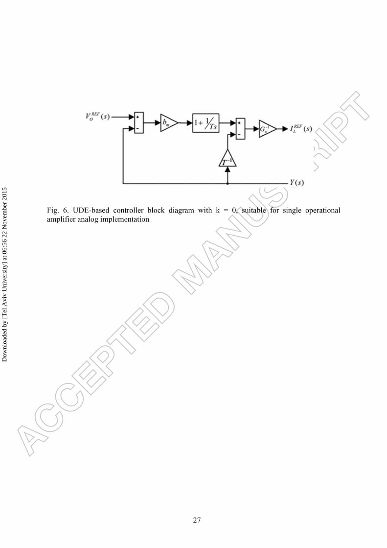
When assuming k = 0, two remarks should be made. First, the controller reduces to the
structure shown in Fig. 6, which was recently shown to be suitable for single operational
amplifier analog implementation in (Sitbon, Schacham & Kuperman, 2015)
Second, (24) can be rearranged as
( ) ( )1 1 1
1
1 2
1 1( ) 1 ( ) 1 ( )
( ) ( ) ( ) ( )
REF REFL n m O n m
m
REFO
I s G b V s G T b Y sTs T b s
H s V s H s Y s
⎛ ⎞⎡ ⎤ ⎜ ⎟= + + +⎢ ⎥ ⎜ ⎟+⎣ ⎦ ⎝ ⎠=
, (25)
revealing the two-degrees-of-freedom nature of the controller which consists of two PI
actions: prefilter H1(s) and feedback controller H2(s). The overall closed loop system is
shown in Fig. 7 and will be used for stability and robustness analysis and in the following
section.
IV. CONTROLLER DESIGN EXAMPLE
Consider a battery powered system, based on the multi-mode, unidirectional buck-boost
DC-DC converter, shown in Fig. 2. The converter is feeding a dynamic load and is supplied by
a Li-Ion battery pack of 4 series connected cells. As a result, the input voltage of the converter
may vary from 4·4.2 = 16.8 V (full pack) down to 4·2.5 = 10 V (empty pack) while the load
voltage is required to be regulated to a constant level of = 13 V. The modulator is
designed such that the converter operates in buck mode when the input voltage is higher than
Dow
nloa
ded
by [
Tel
Avi
v U
nive
rsity
] at
06:
56 2
2 N
ovem
ber
2015

13
14.5 V, in buck-boost mode when the input voltage is between 11.5 V and 14.5 V and in boost
mode when the input voltage reduces below 11.5 V. The current loop is assumed to operate
properly with 10 kHz (20000π rad/s) bandwidth. The values of converter components along
with the values of parasitic elements are given in Table I. Note that neither of the parameters is
known to the controller.
The UDE filter time constant is chosen as T = (2000π)-1[sec/rad] (i.e. equal to 1/10 current
loop bandwidth to allow loop decoupling) while the reference model dynamics is selected as
bm = 20π rad/s (i.e. "low enough" to improve noise immunity since fast tracking is not
required, see the last sentence of Section 2). Nominal capacitance Cn is assumed 500 μF and
Gn is set to . The consequent Bode diagrams of Zm and Z1-Z3 are shown in Fig. 8, where
the frequency characteristics mentioned earlier are evident.
Frequency responses of TUD and noise shaping filters Z12(s) = Z1(s)·Z2(s) and Z13(s) =
Z1(s)·Z3(s) are shown in Figs. 9 and 10, respectively. Obviously, the TUD is processed by a
band-pass filter with worst-case attenuation of around -95 dB while the noise is shaped by a
low-pass filter with corner frequency of around 9500 kHz (60 krad/s). Hence, the converter
switching frequency should be selected above this corner frequency in order to attenuate
switching noise and was set to 100 kHz (200π krad/s) in the simulations.
The family of the plant Bode diagrams ( ) = ( )( ) obtained by linearizing (6) around
an operating point given by vIN = VIN , vO = VO and iO = IO as (Erickson & Maksimovic,
2001)
Dow
nloa
ded
by [
Tel
Avi
v U
nive
rsity
] at
06:
56 2
2 N
ovem
ber
2015

14
( )( )
2
1
2
1
1,
1( ) ,
1
1,
1
IN O O IN
O O O
O IN O ININ
O IN O O
buckCs
V LI V V sP s boost
I CV I s
I L V V V sVbuck boost
I C V V I s
⎧⎪⎪⎪ ⎪
= ⎨+⎪
⎪ +⎪ ⎪ + +⎩
(26)
is shown in Fig. 11 for the input voltages of 10 < vIN < 16.8 V and output currents of 1 A < iO
< 5 A. It may be concluded that the plant undergoes significant variation upon both mode and
operation point changes, acting as an integrator in buck mode and lag-lead in boost and buck-
boost modes. Moreover, while the plant is represented by a single transfer function in the
buck mode, multiple transfer functions characterize the plant in other two modes due to
nonlinearity.
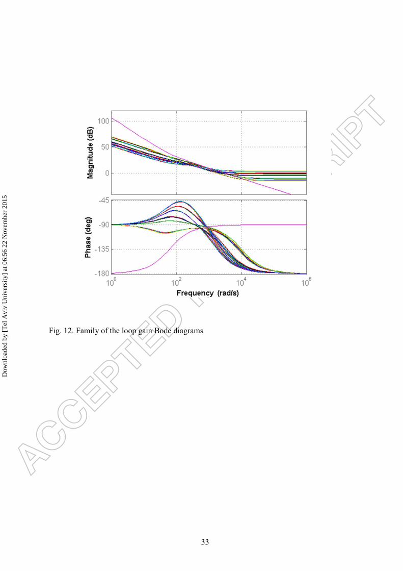
Corresponding family of loop gains P(s)H2(s) (cf. Fig. 7) is shown in Fig. 12. As expected,
the bandwidth of the loop gain is circa T-1 for all operation points and mode. Moreover, the
loop is stable with the worst case phase margin of 45o. This demonstrate the robustness of the
controller, allowing to achieve nearly constant bandwidth and phase margin despite plant
nonlinearities (leading to multiple transfer function representation shown in Fig. 11).
The family of tracking transfer functions ( )( ) = ( ) ( )( ) ( ) is shown in Fig. 13.
Note that following (11), the tracking transfer functions should follow the reference model
Zm(s), defined by a first-order low-pass filted with the cutoff frequency of bm = 20π rad/s.
According to Fig. 13, all the tracking transfer functions closely follow the reference model
whithin the bandwidth of interest, again validating the controller robustness. It should be
noted that the tracking transfer function do diverge beyond the bandwidth of interest, which
is of course irrelevant for closed loop performance.
Dow
nloa
ded
by [
Tel
Avi
v U
nive
rsity
] at
06:
56 2
2 N
ovem
ber
2015

15
V. TIME-DOMAIN SIMULATION RESULTS
A. Performance verification
The system under investigation was simulated using PSIM software. Simulation circuit is
shown in Fig. 14. The battery pack is modeled using a variable voltage source while the load
consists of passive and active components. A 13 Ω resistor represents constant resistive load
component while pulsed current load of 1A average, 2 A peak-to-peak plays the role of the
dynamic component. Voltage controller is implemented according to (24), driving the
average current controller and modulator, designed folowing the guidelines given in (Aharon,
Kuperman, & Shmilovitz, 2015).
Two simulations were carried out. In the first, output voltage reference was held at 13 V
while input voltage was reduced ramp-like from 16.8 V (full battery) down to 10 V (depleted
battery). The results are shown in Fig. 15. The converter passes through three operating
modes with the reduction of battery voltage, yet dynamic response to load changes and zero
steady state error remain nearly unaltered despite mode transitions. The control signal
(inductor current reference ) is shown as well along with actual inductor current iL to
validate correct operation of the current controller.
In the second simulation, tracking capabilities of the controller were examined by altering
the output voltage reference from 10 V to 18 V and back while reducing input voltage ramp-
like from 16.8 V (full battery) down to 10 V (depleted battery) and keeping the constant load
current of 3 A . The result is shown in Fig. 16. It may be concluded that the system follows
the reference model precisely.
B. Comparison to PI control
The purpose of the comparison below is demonstrating that the two-degrees-of-freedom
controller is capable of decoupling tracking and disturbance rejection performance while the
classical PI controller is not. Following (9), a PI controller is designed as
Dow
nloa
ded
by [
Tel
Avi
v U
nive
rsity
] at
06:
56 2
2 N
ovem
ber
2015

16
( )2
1( ) 2 ,dPI n dC s G
s
⎛ ⎞⎜ ⎟= +⎜ ⎟⎝ ⎠
(27)
where ωd rad/s is the desired nominal bandwidth. It is well-known that in case a PI controller
is utilized, tracking and disturbance rejection are coupled (Zhang, Xi, Yang & Xu, 2002).
Consequently, in case the controller is designed to match the tracking bandwidth of the UDE-
controlled system (i.e. ωd = 20π rad/s), the disturbance rejection is expected to be sacrificed.
Simulation result, comparing tracking voltage error − of UDE and PI based
controllers under the conditions of the first simulation above is shown in Fig. 17. As expected,
the PI controller fails to assure decent tracking performance since the resulting disturbance
rejection capabilities are insufficient.
VI. CONCLUSIONS
A method of designing a linear robust controller for nonlinear uncertain single input single
output systems with external disturbances, based on Uncertainty and Disturbance Estimator
theory was proposed in the paper. The approach was successfully applied to control the
output voltage of a unidirectional multi-mode buck-boost converter. By quickly estimating
and canceling the uncertainties and disturbances, the controller forces the system to maintain
nearly nominal performance through the whole range of operating points. Despite the
relatively non-trivial and complex underlying theory, the resulting controller structure turns
out to be relatively simple, allowing low cost analog implementation with low part count.
Extended simulation results were presented to demonstrate the feasibility of the proposed
method.
ACKNOWLEDGEMENT
The research was partially supported by the Ministry of National Infrastructures, Energy
and Water Resources of Israel.
Dow
nloa
ded
by [
Tel
Avi
v U
nive
rsity
] at
06:
56 2
2 N
ovem
ber
2015

17
References
Aharon I. & Kuperman A. (2011, January). Topological overview of powertrains for
battery powered vehicles with range extenders. IEEE Trans. Power Electron., 26(3), 868-
876.
Aharon I. & Kuperman A. (2011, February). Battery-ultracapacitor hybrids for pulsed
current loads: A review. Renew. Sust. Energy Rev., 15(2), 981-992.
Aharon I., Kuperman A., & Shmilovitz D. (2015, February). Analysis of dual-carrier
modulator for bidirectional non-inverting buck-boost converter. IEEE Trans. Power
Electron., 30(2), 840 – 848.
Aharon I., Kuperman A. & Shmilovitz D. (2013, November) Analysis of a bidirectional
buck-boost converter for energy storage applications. in Proc. 39th IECON, November 10-13,
Vienna.
Chandar T. S. & Talole S. E. (2014, August). Improving the performance of UDE-based
controller using a new flter design. Nonl. Dyn., 77(3), 753–768.
Chen Z. (2012, June). Double loop control of buck-boost converters for wide range of load
resistance and reference voltage. IET Control Theory and Appl., 6(7), 900 – 910.
Erickson R. W. & Maksimovic D. (2001, January). Fundamentals of Power Electronics
Second Edition. Kluwer Academic.
Kolhe J. P., Shaheed M., Chandar T. S., & Talole S. E. (2013, January). Robust control of
robot manipulators based on uncertainty and disturbance estimation. Int. J. Robust Nonl.
Contr., 23(1), 104–122.
Kuperman A. (2015, July). Design of α-filter-based UDE controllers considering finite
control bandwidth. Nonl. Dyn., 81(1), 411–416.
Kuperman A., Aharon I., Malki S. & Kara. A. (2013, February). Design of a semiactive
battery-ultracapacitor hybrid energy source. IEEE Trans. Power Electron., 28(2), 806–815.
Dow
nloa
ded
by [
Tel
Avi
v U
nive
rsity
] at
06:
56 2
2 N
ovem
ber
2015

18
Kuperman A. & Zhong Q.-C. (2011, January). Robust control of uncertain nonlinear
systems with state delays based on an uncertainty and disturbance estimator. Int. Jour. Nonl.
Robust Contr, 21(1), 79 – 92.
Kuperman A. & Zhong Q.-C. (2013, Februray). Disturbance observer assisted robust
control of wing rock motion based on contraction theory. Simulation, 89(9), 1128 – 1136.
Kuperman A. & Zhong Q.-C. (2015, July). UDE-based linear robust control for a class of
nonlinear systems with application to wing rock motion stabilization. Nonl. Dyn., 81(1), 789–
799.
Lee Y. H., Huang S. C., Wang S. W., Wu W. C., Hung P. C., Ho H. H., Lai Y. T. & Chen
K. H. (2012, March). Power-tracking embedded buck–boost converter with fast dynamic
voltage scaling for SoC system. IEEE Trans. Power Electron., 27(3), 1270–1282.
Lee Y. J., Khaligh A. & Emadi A. (2009, April). A compensation technique for smooth
transitions in a noninverting buck–boost converter. IEEE Trans. Power Electron., 24(4), 1002
– 1016.
Lee Y. J., Khaligh A., Chakraborty A. & Emadi A. (2009, May). Digital combination of
buck and boost converters to control a positive buck–boost converter and improve the output
transients. IEEE Trans. Power Electron., 24(5), 1267-1279.
Leyva-Ramos J., Ortiz-Lopez M., Diaz-Saldierna L. & Morales-Saldana J. (2009,
September). Switching regulator using a quadratic boost converter for wide DC conversion
ratios. IET Power Electron., 2(5), 605 - 613.
Linarez-Flores J., Hernandez Mendez A., Garcia-Rodriguez C. & Sira-Ramirez H. (2014,
August). Robust nonlinear adaptive control of a boost converter via algebraic parameter
identification. IEEE Trans. Ind. Electron., 61(8), 4105 – 4114.
Linares-Flores J., Barahona-Avalos J., Sira-Ramirez H. & Contreras-Ordaz, M. (2012,
June). Robust passivity-based control of a buck–boost-converter/DC-motor system: An active
Dow
nloa
ded
by [
Tel
Avi
v U
nive
rsity
] at
06:
56 2
2 N
ovem
ber
2015

19
disturbance rejection approach. IEEE Trans. Ind. Appl., 48(6), 2362 – 2371.
Lopez-Santos O., Martinez-Salamero L, Garcia G., Valderrama-Blavi H. & Sierra-Polanco,
T. (2015, May). Robust sliding-mode control design for a voltage regulated quadratic boost
converter. IEEE Trans. Power Electron., 30(4), 2313 – 2327.
Maccari L., Montagner V., Pinheiro H. & Oliveira R. (2012, August). Robust H2 control
applied to boost converters: design, experimental validation and performance analysis. IET
Control Theory Appl., 6(12), 1881 – 1888.
Olalla C., Leyva R., El Aroudi A., Garces P. & Queinnec I. (2010, January). LMI robust
control design for boost PWM converters. IET Power Electron., 3(1), 75 - 85.
Olalla C., Leyva R., El Aroudi A., Garces P. & Queinnec I. (2009, July). Robust LQR
control for PWM converters: An LMI approach. IEEE Trans. Ind. Electron., 56(7), 2548 -
2558.
Phadke S. B. & Talole S. E. (2012, October). Sliding mode and inertial delay control based
missile guidance. IEEE Trans. Aerosp. Electron. Syst., 48(4), 3331–3346.
Restrepo C., Calvente J., Romero A., Vidal-Idiarte E. & Giral R. (2009, May) Current-
mode control of a coupled inductor buck-boost DC-DC switching converter. IEEE Trans.
Power Electron., 27(5), 2536 – 2549.
Restrepo C., Calvente J., Cid-Pastor A., Aroudi A. E. & Giral R. (2011, September). A
non-inverting buck–boost dc–dc switching converter with high efficiency and wide
bandwidth. IEEE Trans. Power Electron., 26(9), 2490–2503.
Sahu B. & Rincon-Mora G. A. (2004, March). A low voltage, dynamic, noninverting,
synchronous buck–boost converter for portable applications. IEEE Trans. Power Electron.,
19(2), 443–452.
Sitbon M., Schacham S. & Kuperman A. (2015, May). Disturbance observer based voltage
regulation of current-mode-boost-converter-interfaced photovoltaic generator. IEEE Trans.
Dow
nloa
ded
by [
Tel
Avi
v U
nive
rsity
] at
06:
56 2
2 N
ovem
ber
2015

20
Ind. Electron., DOI: 10.1109/TIE.2015.2434796.
Stobart R., Kuperman A. & Zhong Q.-C. (2011, January). Uncertainty and disturbance
estimator (UDE) based control of uncertain linear systems with statedelays. Jour. Dyn. Sys.
Meas. Con. - Trans. ASME, 133(2), 1 – 6.
Su S. & Lin Y. (2011, November). Robust output tracking control of a class of non-minimum
phase systems and application to VTOL aircrafts. Int. J. Contr., 84(11), 1858–1872.
Su S. & Lin Y. (2013, July). Robust output tracking control for a velocity-sensorless vertical
take-off and landing aircraft with input disturbances and unmatched uncertainties. Int. J.
Robust Nonl. Contr., 23(11), 1198–1213.
Talole S. E. & Phadke S. B. (2008, May). Model following sliding mode control based on
uncertainty and disturbance estimator. Jour. Dyn. Sys. Meas. Con. - Trans. ASME, 130(3), 1 –
6.
Talole S. E. & Phadke S. B. (2009, October). Robust input-output linearization using
uncertainty and disturbance estimation. Int. J. Contr., 82(10), 1794–1803.
Talole S. E., Chandar T. S., & Kolhe J. P. (2011, May). Design and experimental validation
of UDE based controller-observer structure for robust input-output linearization. Int. J.
Contr., 84(5), 969–984.
Wei C. L., Chen C. H., Wu K. C. & Ko I. T. (2012, December). Design of an average current
mode noninverting buck-boost dc-dc converter with reduced switching and conduction
losses. IEEE Trans. Power Electron., 27(12), 4934–4942.
Zhang W., Xi Y., Yang G. & Xu X. (2002, October). Design PID controllers for desired
time-domain or frequency-domain response. ISA Trans., 41(4), 511 – 520.
Zhong Q. C. & Rees D. (2004, March). Control of uncertain LTI systems based on an
uncertainty and disturbance estimator. Jour. Dyn. Sys. Meas. Con. - Trans. ASME, 126(1),
905-910.
Dow
nloa
ded
by [
Tel
Avi
v U
nive
rsity
] at
06:
56 2
2 N
ovem
ber
2015

21
Zhong Q. C., Kuperman A. & Stobart R. (2011, November). Design of UDE-based
controllers from their two-degree-of-freedom nature. Int. Jour. Nonl. Robust Contr., 21(17),
1994 – 2008.
Dow
nloa
ded
by [
Tel
Avi
v U
nive
rsity
] at
06:
56 2
2 N
ovem
ber
2015

22
Fig. 1. Typical cascaded control structure of a power converter
Dow
nloa
ded
by [
Tel
Avi
v U
nive
rsity
] at
06:
56 2
2 N
ovem
ber
2015

23
Fig. 2. Multimode noninverting unidirectional DC-DC converter
Dow
nloa
ded
by [
Tel
Avi
v U
nive
rsity
] at
06:
56 2
2 N
ovem
ber
2015

24
Fig. 3. Modulator structure (top) and corresponding waveforms (bottom).
Dow
nloa
ded
by [
Tel
Avi
v U
nive
rsity
] at
06:
56 2
2 N
ovem
ber
2015

25
Fig. 4. Average model of the converter
Dow
nloa
ded
by [
Tel
Avi
v U
nive
rsity
] at
06:
56 2
2 N
ovem
ber
2015

26
Fig. 5. UDE-based controller block diagram
Dow
nloa
ded
by [
Tel
Avi
v U
nive
rsity
] at
06:
56 2
2 N
ovem
ber
2015
27
Fig. 6. UDE-based controller block diagram with k = 0, suitable for single operational amplifier analog implementation
Dow
nloa
ded
by [
Tel
Avi
v U
nive
rsity
] at
06:
56 2
2 N
ovem
ber
2015

28
Fig. 7. Overall UDE controller based control-oriented closed loop diagram
Dow
nloa
ded
by [
Tel
Avi
v U
nive
rsity
] at
06:
56 2
2 N
ovem
ber
2015

29
Fig. 8. Frequency responses of filters Zm and Z1-Z3
Dow
nloa
ded
by [
Tel
Avi
v U
nive
rsity
] at
06:
56 2
2 N
ovem
ber
2015

30
Fig. 9. Frequency response of TUD shaping filter Z12
Dow
nloa
ded
by [
Tel
Avi
v U
nive
rsity
] at
06:
56 2
2 N
ovem
ber
2015

31
Fig. 10. Frequency response of noise shaping filter Z13
Dow
nloa
ded
by [
Tel
Avi
v U
nive
rsity
] at
06:
56 2
2 N
ovem
ber
2015

32
Fig. 11. Family of the plant Bode diagrams
Dow
nloa
ded
by [
Tel
Avi
v U
nive
rsity
] at
06:
56 2
2 N
ovem
ber
2015
33
Fig. 12. Family of the loop gain Bode diagrams
Dow
nloa
ded
by [
Tel
Avi
v U
nive
rsity
] at
06:
56 2
2 N
ovem
ber
2015

34
Fig. 13. Family of the tracking transfer function Bode diagrams
D
ownl
oade
d by
[T
el A
viv
Uni
vers
ity]
at 0
6:56
22
Nov
embe
r 20
15

35
Fig. 14. PSIM simulation setup
Dow
nloa
ded
by [
Tel
Avi
v U
nive
rsity
] at
06:
56 2
2 N
ovem
ber
2015

36
Fig. 15. Disturbance rejection simulation results (from top to bottom): Load current; Input voltage; Reference and output voltages; Reference and inductor currents.
Dow
nloa
ded
by [
Tel
Avi
v U
nive
rsity
] at
06:
56 2
2 N
ovem
ber
2015

37
Fig. 16. Tracking simulation results (from top to bottom): Load current; Input voltage; Reference and output voltages; Reference and inductor currents.
Dow
nloa
ded
by [
Tel
Avi
v U
nive
rsity
] at
06:
56 2
2 N
ovem
ber
2015

38
Fig. 17. Output voltage tracking error of 20π rad/s bandwidth UDE and PI controllers
Dow
nloa
ded
by [
Tel
Avi
v U
nive
rsity
] at
06:
56 2
2 N
ovem
ber
2015

39
TABLE I CONVERTER COMPONENTS VALUES
Parameter Value Units
Inductance L 0.1 mH
ESR(L) 5 mΩ
Capacitance C 940 μF
ESR(C) 1 mΩ
RDSon(T1) 20 mΩ
RDSon(T2) 20 mΩ
VDon(D1) 0.5 V
VDon(D2) 0.5 V
Switching frequency Fs 100 kHz
Dow
nloa
ded
by [
Tel
Avi
v U
nive
rsity
] at
06:
56 2
2 N
ovem
ber
2015