robotics for inspection and decommissioning of …...robotics for inspection and decommissioning of...
TRANSCRIPT

Robotics for Inspection and Decommissioning
of Nuclear Power Plant
Professor Tariq Sattar
London South Bank Innovation Centre

1. Inspect Pressure Vessel shell and nozzle welds
2. Inspect nozzle welds in the primary circuit of nuclear
power plant
3. Inspect radiation cells, stacks, buildings
4. Cut steel objects for nuclear decommissioning
Robots developed by LSBIC to

Circumferential weld
Nozzle weld
to safe end
Nozzle weld to
shell
Upper shell
Lower shell
Bottom head
RPV Circumferential and Nozzle welds
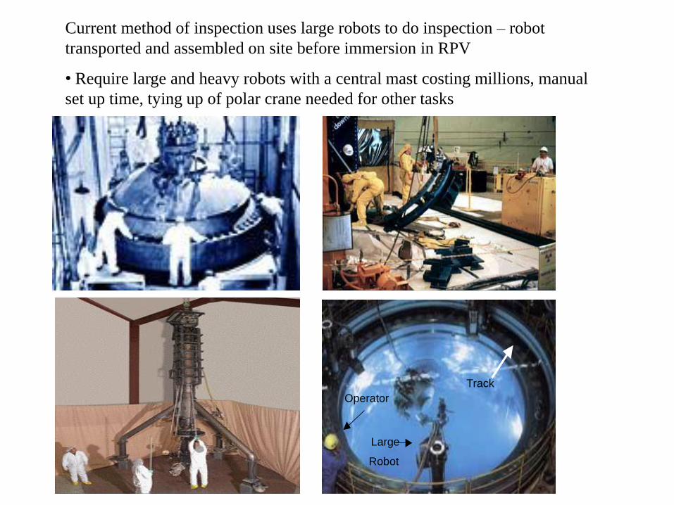
Large
Track
Operator
Robot
Current method of inspection uses large robots to do inspection – robot
transported and assembled on site before immersion in RPV
• Require large and heavy robots with a central mast costing millions, manual
set up time, tying up of polar crane needed for other tasks

Drawing of the pipe crawling robot and
scanning arm inside a nozzle

Nozzle inspection robot
SA1 - electronic compartment that actuates the ROV plus the pan/tilt camera for visual inspection inside the RPV nozzle.
SA2 - structure holds 2 motors to actuate tracks (SA4) and provide rotation of nozzle inspection arm
SA3 - actuation module forces simultaneously the tracks towards the nozzle. RPV nozzle is an axis symmetric shape with continuously variable diameter, the tractor support (SA3) provides suspension capabilities in order to cope with the nozzle diameter change.
The tracks are 400mm in length, 100mm in width and height.
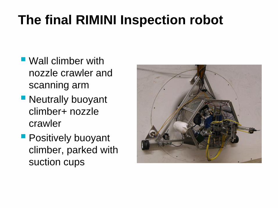
The final RIMINI Inspection robot
Wall climber with
nozzle crawler and
scanning arm
Neutrally buoyant
climber+ nozzle
crawler
Positively buoyant
climber, parked with
suction cups

Design of a versatile robot for
inspection of welds with complex
contours in nuclear power plant

• Prototype generic, mobile inspection tool
• Compact robot + 7 axis robot arm + 5 kg
payload of NDT sensors to test welds
• Climbing motion over highly curved
surfaces of any material- 860 mm diameter
pipes and 3 m pressure vessel
• Couplant retrieval system
Nuclear Inspection Robot
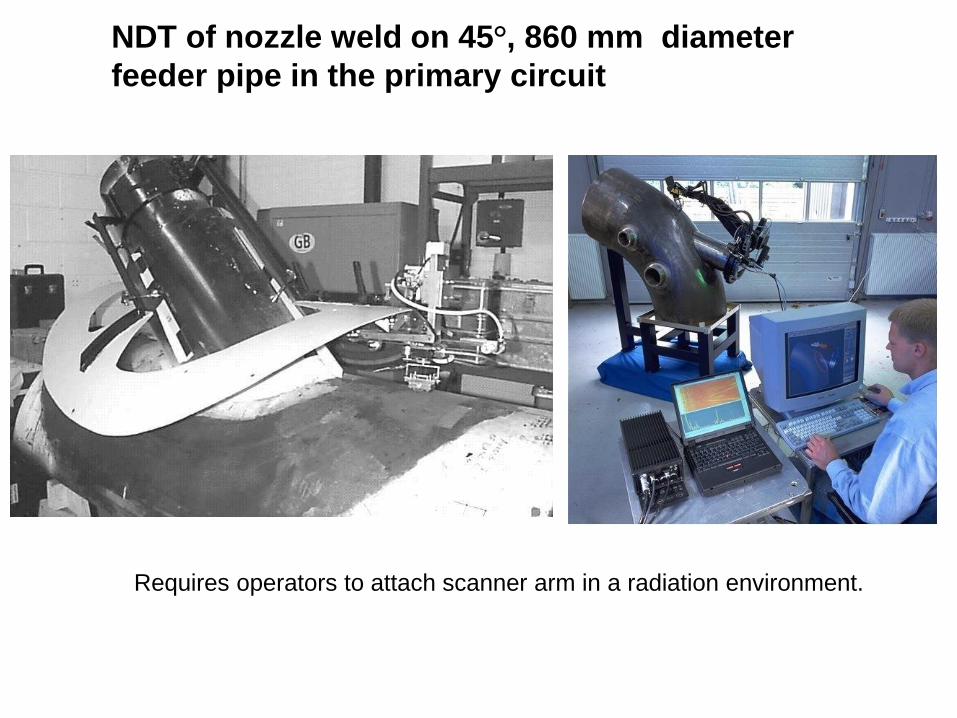
NDT of nozzle weld on 45°, 860 mm diameter
feeder pipe in the primary circuit
Requires operators to attach scanner arm in a radiation environment.
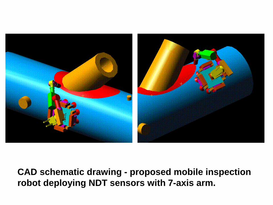
CAD schematic drawing - proposed mobile inspection
robot deploying NDT sensors with 7-axis arm.

Mechanical Design: Key Concepts •Thigh Hinges tilt leg
pairs relative to the
vehicle chassis
•Universal ankle joints
made alternately free
during walking step,
otherwise locked rigid for
vehicle stability during
the data acquisition
stages
•Suction feet adapt and
adhere to curved surfaces
whilst remaining
sufficiently rigid for
vehicle stability
V
Payload platform Thigh hinge
Thigh cylinder
Ankle joint
Suction foot
Shank cylinder
V
V
V

Seal rubber
Suction cup
Shank cylinder
Piston rod
Lockable ankle
Vacuum
pump
Vacuum pump
Air supply
V
w
Novel Universal Ankle Joint - alternately
flexible or rigid by means of a double
vacuum system.

Prototype generic vehicle - 4 thigh joints for
motion on spheres -conventional suction
cups -payload 6 kg with a safety factor of 3
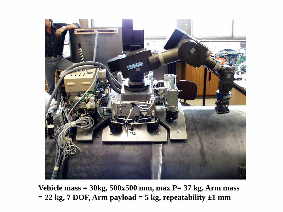
Vehicle mass = 30kg, 500x500 mm, max P= 37 kg, Arm mass
= 22 kg, 7 DOF, Arm payload = 5 kg, repeatability ±1 mm


Nuclear Inspection
Robot at the SOGIN
nuclear power plant
in Torino, Italy.
Shown scanning
nozzle welds on a 6
ton mock-up of a
stainless steel
pressure vessel.
The Climbing
Robot

Inspection (1) – Large Structures and Buildings
• Rebar at 50mm depth
• Faces/surfaces have safety implications for scaffold/rope access, remote
measurements advantageous.
• Simple structural geometries suitable for ROV.
Inspection (2) – Aerial Stacks
• Concrete re-enforced curved stacks over 100ft high, diameters 2 -8 m at the base.
• Associated with ventilation systems for nuclear safety purposes. ROV minimises
downtime if the internals are to be inspected by avoiding man access near to the
outlet that fundamentally makes a task safer.
• ROV required to inspect the internals of an operational stack, with the associated
air flows and velocities.
• External examination of stack expected.
Sellafield Site

Inspection (3) – Internal Radiation Contaminated Cells
• Store plant, vessels, pipework and other devices
• Concrete and rebar construction and clad with stainless steel
2-3mm thick with a transition part way up the wall (if not fully
clad)
• Floors of these cells are also clad with stainless steel,
demanding a high friction medium for traction. Accumulations
of dusts/loose debris are possible
• ROV introduced via man-access door or cell wall penetration
• Walls range from 200 to 1800mm thick
• The cell wall penetrations are as small as 150 to 200mm in
diameter

Inspection of
Nuclear
infrastructure with
mobile ROV
Permanent Magnet
Adhesion Climbing Robot
for inspection of large
concrete structures e.g.
• Stacks
• Radiation Cells
• Buildings
• Civil engineering
structures

Features
• Uses magnetic flux focussing
techniques to adhere to steel rebars
• Zero energy adhesion with
permanent magnets
• Longer operating time with battery
powered robots
• Robot remains safely attached
during power failure

VORTEX MACHINES: Wall climbing robots for NDT, inspection and surveillance on non-ferrous surfaces

DEPLOYMENT OF LASER CUTTING HEAD WITH WALL CLIMBING
ROBOT FOR NUCLEAR DECOMMISSIONING
Tariq P. Sattar
Paul Hilton
Md Omar Faruq Howlader

Demonstration of STRONGMAN carrying TWI laser cutting tool
for nuclear decommissioning – 21 September 2016
The Lasersnake2 R&D project funded by the UK Technology Strategy Board, the
Department for Energy and Climate Change, and the Nuclear Decommissioning
Authority is using snake arms to deploy laser cutting heads

Advanced Wall climbing robot for the inspection of welds on cargo
containers ships
Permanent
magnets
Wireless
control and
data
acquisition
Ultrasonic
phased array
NDT
Mass 35Kg

Climbing Robot Cell for welding and NDT - CROCELLS
Team of climbing robots
One performs Electric arc welding by profiling seam with a laser system
A utility robot follows the welder and carries the wire drum and feeder
A tug robot aides the welding robot
An NDT robot tracks the welding hot spot and performs weld inspection with phased array ultrasonics

The nuclear decommissioning task
Operators require technology to cut steel structures
that:
• Is highly automated and remotely operated
• Delivers noncontact dismantling & cut most
materials
• Produces minimum secondary waste
• Works at a high speed
• Is reusable in many decommissioning processes
Laser cutting technology meets requirements
• Solid-state lasers, with optical fibre delivery of laser power,
reduce complexity and risks, providing laser power in the
multi-kilowatt regime with good focus ability of the delivered
beam
• High value asset, which is the laser itself, situated and
maintained in a safe clean area, remote from the cutting
• Commercially available laser technology, at powers of the
order 5kW, is well capable of cutting material up to 50mm
in thickness

The Laser cutting system
• 5kW fibre laser, manufactured by IPG Photonics,
• 30m long, 150 micron core diameter optical fibre delivers power to a cutting
head.
• Cutting head uses 120mm focal length collimating lens makes the diverging
beam emerging from the end of the fibre, parallel.
• This beam is then diverted through 90 degrees to a focusing lens of length
250mm, to form a focused spot of about 0.4mm in diameter.
• A cut kerf is formed by blowing away the molten material with a jet of
compressed gas. For decommissioning applications, cut quality is not really an
issue so compressed air (for cheapness) is used as the assist gas.
• The maximum cutting speed, for a given thickness, depends primarily on the
applied laser power, the position of the laser beam focus with respect to the
surface of the material and the pressure and composition of the cutting assist
gas.

Climbing robot carrying laser
cutter head to cut on the right
side
Cutting head positioned 15mm
above plate, 45° w.r.t. robot


END