robotics and mechatronics lab - articulated hybrid …rmlab.org/pdf/j8_mechatronics.pdfarticulated...
TRANSCRIPT

Mechatronics 20 (2010) 627–639
Contents lists available at ScienceDirect
Mechatronics
journal homepage: www.elsevier .com/ locate/mechatronics
Articulated hybrid mobile robot mechanism with compounded mobilityand manipulation and on-board wireless sensor/actuator control interfaces
Pinhas Ben-Tzvi a,*, Andrew A. Goldenberg b, Jean W. Zu b
a The George Washington University, Department of Mechanical and Aerospace Engineering, Robotics and Mechatronics Lab, 801 22nd St., NW, Washington, DC 20052, United Statesb University of Toronto, Department of Mechanical and Industrial Engineering, 5 King’s College Road, Toronto, ON M5S 3G8, Canada
a r t i c l e i n f o
Article history:Received 17 October 2009Accepted 7 June 2010
Keywords:Mobile robotControl hardware architectureSimulationsPrototype integrationWireless communicationSearch and rescue
0957-4158/$ - see front matter � 2010 Elsevier Ltd. Adoi:10.1016/j.mechatronics.2010.06.004
* Corresponding author. Tel.: +1 202 994 6149; faxE-mail address: [email protected] (P. Ben-Tzvi).
a b s t r a c t
This paper presents the development of a remotely operated mobile robot system with a hybrid mecha-nism whereby the locomotion platform and manipulator arm are designed as one entity to support bothlocomotion and manipulation interchangeably. The mechanical design is briefly described as well as thedynamic simulations used to analyze the robot mobility and functionality. As part of the development,this paper mainly focuses on a new generalized control hardware architecture based on embedded on-board wireless communication network between the robot’s subsystems. This approach results in a mod-ular control hardware architecture since no wire connections are used between the actuators and sensorsin each of the mobile robot subsystems and also provides operational fault-tolerance. The effectiveness ofthis approach is experimentally demonstrated and validated by implementing it in the hybrid mobilerobot system. The new control hardware architecture and mechanical design demonstrate the qualitativeand quantitative performance improvements of the mobile robot in terms of the new locomotion andmanipulation capabilities it provides. Experimental results are presented to demonstrate new operativetasks that the robot was able to accomplish, such as traversing challenging obstacles, and manipulatingobjects of various capacities; functions often required in various challenging applications, such as searchand rescue missions, hazardous site inspections, and planetary explorations.
� 2010 Elsevier Ltd. All rights reserved.
1. Introduction
Mobile robots have been used in the aftermath of September 11,2001 for USAR (Urban Search and Rescue) activities such as: struc-tural inspection, searching for victims, searching paths through therubble that would be quicker than to excavate, and detection ofhazardous materials. In each case, small mobile robots were usedbecause they could go deeper than traditional search equipmentand could enter void spaces too small for a human or search dog.Among the tracked robots that were used, the capability was lim-ited in terms of locomotion and mobility, and more so if one con-siders requirements to perform manipulation tasks with an armmounted on the mobile robot. One of the other problems withsome of the robots used on the rubble pile searches were the robotflipping over into a position from where it could not be righted ormoved [6].
Increasingly, mobile robotic platforms are being proposed forhigh-risk missions for law enforcement and military applications(e.g., to manipulate Improvised Explosive Devices – IEDs), hazard-ous site clean-ups, planetary explorations (e.g., Mars Rover), andrough terrain such as in collapsed buildings, disaster areas, caves
ll rights reserved.
: +1 202 994 0238.
and other outdoor environments. In those missions, small mobilerobots are strictly limited by geometry since even the smallestobstacle can hinder mobility simply by physics. For instance, sucha limitation occurs with wheeled mobile robots due to wheelbaseand in legged robots due to limited leg step height and minimalcontact area, etc. Another factor could be the result of actuatorstrength compared to the mobile robot mass. To solve the mobilityproblems of wheeled and legged locomotion, tracks are often used.
There are various designs of tracked mobile robots that have op-tional feature in the design to attach a manipulator arm on top ofthe mobile platform as an add-on system or part of the platform.Some of the robots are: Talon [9], PackBot [24], Andros Mark V ro-bots [23], Wheelbarrow MK8 [8], AZIMUT [18], LMA [11], Matilda[19], Helios VI and VII robots [13,12], Variable configuration VCTV[14], and Ratler [20]. Some legged robots [21,10,7,15] are also partof the scenarios assumed herewith, but they may not fall under theaforementioned category of applications due to their limited legstep height and minimal contact area (limited traction). Therefore,our focus is on tracked mobile robots that besides locomotion ex-hibit manipulation capabilities.
Typically, state-of-the-art tracked mobile robots have a sepa-rate manipulator arm platform attached on top of the locomotionplatform. The platforms provide distinct functions. Namely, thelocomotion platform provides mobility with a pair of tracks,

628 P. Ben-Tzvi et al. / Mechatronics 20 (2010) 627–639
wheels [1,22] or the combination of both, and the arm platformprovides manipulation (manipulation of hazardous materials, neu-tralization of bombs or landmines, etc.). Furthermore, the presenceof an arm limits the mobility, mainly because it is attached on topof the mobility platform and as such, platform flip-over may not bepossible. On the other hand, there are several designs of mobile ro-bots with enhanced mobility capability on the account that theyare not equipped with a manipulator arm on top. We propose tobridge this gap in our approach by providing a new remotely oper-ated mobile robot design that provides compounded manipulationand locomotion capabilities. The significance of the new mobile ro-bot mechanism is that it has the ability to interchangeably providelocomotion and manipulation capability, both simultaneously. Thiswas accomplished by integrating the locomotion and manipulatorarm mechanisms as one entity resulting in a hybrid articulatedmechanism rather than two separate and attached mechanisms.The manipulator arm can be used as part of the locomotion plat-form and vice versa. The platform and manipulator are inter-changeable in their roles in the sense that both can supportmanipulation and locomotion in several configuration modes asdiscussed in Section 2.2.
In order to provide a modular mechanical and control systemarchitecture (to satisfy a set of requirements for better kinematicfunctionality, as discussed in Section 4 under ‘requirements’), thelinks or subsystems constituting the mobile robot are connectedwirelessly. This, along with an independent power source in eachsubsystem, eliminates the need for physical wiring between therotating articulated mobile robot links. The developed novel on-board wireless sensor/actuator control paradigm and the relatedelectrical hardware architecture are discussed in detail in Sections4 and 5, respectively.
A thorough review of the literature assisted us in deriving a con-ceptual function-oriented analysis [3,5]) in order to qualitativelyidentify the major issues related to mobile robots functionality infield operations. This analysis has led to the design approach. Abrief summary of the issues, related research problems and pro-posed solutions are summarized in Table 1.
This paper is organized as follows. Section 2 provides a briefdescription of the mobile robot design. In Section 3, relevant sim-ulation results that assisted with the design development are pre-sented, and then compared with the experimental resultsperformed with the physical prototype, as presented in Section 6.Sections 4 and 5 present the new generalized systematic approachfor modular control hardware architecture with on-board distrib-uted wireless communication network between the robot’s sub-systems and modules. This approach is then implemented as partof the hybrid mobile robot (HMR) System development. Section 6provides extensive experimental results and discussions. Theexperiments demonstrate the coincidence and hence the validity
Table 1Summary of issues, related research problems, and proposed solutions.
Issue Research problem Proposed solution
Manipulator armand mobileplatform areseparate modules
Each modulecontributes to designcomplexity, weightand cost
Design the manipulator armand mobile platform as oneentity mechanism
Manipulator armmounted orfolded on top
Arm susceptible tobreakage and damagewhen platforminverted
Integration of arm andplatform as one entity in ageometrically symmetricdesign eliminates exposure
Flip-overoccurrence:invertibilityversus self-righting
To provide self-righting withoutspecial purpose oractive means
Design a symmetricplatform to allow flip-overwithout the need to returnit, and as such greatlyenhance mobility
of the simulations described in Section 3. They also demonstratehow the embedded wireless control hardware architecture dra-matically increases the locomotion and manipulation functional-ities of the mobile robot.
2. Hybrid mobile robot (HMR) mechanism design
In this section, the mechanical design architecture of the remo-tely controlled HMR mechanism is briefly presented as part of theoverall system development and as a case study for the implemen-tation of the newly proposed control hardware architecture. Indepth details of the mechanical design are available in Ben-Tzviet al. [5].
The proposed design approach is twofold and is described asfollows: (i) integrate the manipulator and the mobility platformas one entity resulting in a hybrid mechanism rather than two sep-arate and attached mechanisms. Consequently, the same joints(motors) that provide the manipulator’s dof’s also provide the mo-bile platform’s dof’s. Therefore, the actuator strength capacity formanipulation purposes dramatically increases due to the hybridmechanical structure and (ii) design the overall mobile robot plat-form in a geometrically symmetric manner in order to allow flip-over and invert-ability. Therefore, when a flip-over takes place,the robot can continue its task from the current position, with noneed of self-righting or added active means to return it.
2.1. Description of the design
The design concept embodying the proposed idea is depicted inFig. 1. If the platform is inverted due to flip-over, the fully symmet-ric design (Fig. 1a) allows the platform to continue to the destina-tion from its new position with no need of active means for self-righting. Also it is able to deploy/stow the manipulator arm fromeither side of the platform.
The platform includes two identical and parallel base link 1tracks (left and right), link 2, link 3, end-effector and passivewheels. To support the symmetric nature of the design, all the linksare nested into one another. Link 2 is connected between the twobase link tracks via joint 1 (Fig. 1b). Passive wheels are inserted be-tween links 2 and 3 and connected via joint 2 and another passivewheel is inserted between link 3 and the end-effector via joint 3(Fig. 1b). The passive wheels are used to support links 2 and 3when used for various configuration modes of locomotion/traction.Link 2, link 3 and the end-effector are connected through revolutejoints and are able to provide continuous 360� rotation and can bedeployed separately or together from either side of the platform.To prevent immobilization of the platform during a flip-over sce-nario, rounded and pliable covers are attached to the sides of theplatform as shown in Fig. 3.
The hybrid mobile robot system is remotely controlled by anoperator using an Operator Control Unit (OCU) as described in de-tail in Section 5.4.
2.2. Configuration modes of operation
The links can be used in three modes: (a) locomotion mode: alllinks used for locomotion to provide added level of maneuverabil-ity and traction; (b) manipulation mode: all links are used formanipulation to provide added level of manipulation. The pair ofbase links can provide motion equivalent to a turret joint of themanipulator arm; (c) hybrid mode: combination of modes (a)and (b) – while some links are used for locomotion, the rest couldbe used for manipulation at the same time, thus the hybrid natureof the design.

Side covers (a) (b)
Joint 2
Joint 1
Joint 3
End-effector
Passive wheels Link 3
(c)
PassiveWheel
Base link 1
Link 2
Fig. 1. (a) Closed configuration; (b) open configuration; and (c) exploded view.
Front LED light
Front CCDCamera
Embedded flat data RF antenna – Fig. 8
Embeded flat Video RF antenna (on left side cover)
Back LED light
Back CCD Camera
Pliable rounded side covers
Passive wheels
Fig. 3. Complete depiction of the hybrid mobile robot.
(b)
Obstacle
(a)
Camera
Locomotion
Manipulation
(c) (d)
Manipulation
Locomotion
Terrain
(f) Locomotion (e)
Manipulation
WP
WP
Fig. 2. (a and b) sample mobility configurations; (c and d) sample manipulationconfigurations; (e and f) configurations for enhanced traction.
Table 2Robot design specifications.
Total mass 65 (kg) Max. Torque inJoint 1 – T1
32 (Nm)
Length (arm stowed) 814 (mm) Max. Torque inJoint 2 – T2
157 (Nm)
Length (arm deployed) 2034 (mm) Max. Torque inJoint 3 – T3
157 (Nm)
Width (with pliableside covers)
626 (mm) Link 1 rotationspeed about joint 1
30 (deg/s)
Height (arm stowed) 179 (mm) Link 2 rotationspeed about joint 1
52 (deg/s)
On-board batterypower
�2.5 h Link 3 rotationspeed about joint 2
52 (deg/s)
Speed of platform up to 1 (m/s) Gripper wrist rotationspeed about joint 3
15 (deg/s)
P. Ben-Tzvi et al. / Mechatronics 20 (2010) 627–639 629
2.3. Maneuverability, traction and manipulation
To qualitatively illustrate the configuration modes, some are de-picted in Fig. 2. More detailed information on the various configu-ration modes is available in Ben-Tzvi [3] and Ben-Tzvi et al. [5].Fig. 2a shows the use of link 2 to support the platform for enhancedmobility purposes as well as climbing purposes. Link 2 also helpsto prevent the robot from being immobilized due to high-center-ing, and it also enables the robot to climb taller objects (Fig. 2b).Link 2 is also used to support the entire platform when movingin a tripod configuration while using the other links for manipula-tion (Fig. 2c). For enhanced traction, the articulated structure of themobile platform allows it to be adaptable to different terrainshapes and ground conditions (Fig. 2f). Fig. 2c–e depict a few ofthe various configurations for manipulation purposes. While somelinks are used for locomotion, the others are used simultaneouslyfor manipulation.
A complete depiction of the mobile robot is shown in Fig. 3.Other accessories typically found in mobile robots such as cameras,lights and antennas, protrude from the platform. In order to pre-vent their exposure to the surrounding and thereby eliminate riskof damage in cases were the robot flips over or falls, the CCD cam-eras, LED lights and antennas were embedded inside the base linktracks, as shown in Fig. 3.
General specifications of the robot are provided in Table 2.The design also includes a built-in dual-operation track tension
and suspension mechanism situated in each of the base link tracks[2]a). The suspension mechanism is also used to absorb some ofthe energy resulting from falling or flipping, thus providing somecompliance to impact forces.
3. Modelling and simulations of the hybrid robot
A detailed 3D mechanical design assembly was developed withADAMS software to perform dynamic simulations of the completerobotic system in order to study its functionality and improve thedesign [4]. The simulation experiments are accounting for the mass
630 P. Ben-Tzvi et al. / Mechatronics 20 (2010) 627–639
distribution of the robot (including batteries, motors, electronics,etc.), inertia properties of the links and contact and friction forcesbetween the links and tracks and the ground.
ADAMS, motion simulation software, was used to analyze thebehavior of the robotic system. It allowed us to test virtual proto-types and enhance designs for performance, without having tobuild and test several physical prototypes. This noticeably reducedour prototype development time and cost.
The design enhancement process involved proper links’weight selection, proper component selection (e.g., springs fortrack tension/suspension; motors, gear ratios), etc. The requisitefor a flexible dynamics capability for the track system was ad-dressed with ADAMS Tracked Vehicle (ATV) Toolkit. A tool usingADAMS and ATV Toolkit was developed and used to model thetracks [16,17].
The simulations were performed for the following major pur-poses: (i) visualize and validate robot mobility characteristicsthrough animations of different possible tasks that require variouslocomotion and manipulation capabilities; (ii) define each joint’storque requirements for different mobility tasks and select propergear ratios and motors; (iii) analyze the suspension and track ten-sion retention by examining the spring array force distributions;and (iv) define maximum end-effector payload capacity for differ-ent robot configurations. Different types of terrains such as flatroads, obstacles, stairs, ditches, and ramps, were created such thatthey could be easily changed according to different size and shaperequirements.
In this section we focus on some of the animation results in or-der to eventually compare them to the experimental results pre-sented in Section 6. This validates the mobility analysisperformed for the purpose of enhancing the design at the early de-sign stages. The simulation results described in items (ii)–(iv)above can be found in Ben-Tzvi et al. [2].
(2) (1)
(a)
(b)
(c)
(d)
(e)
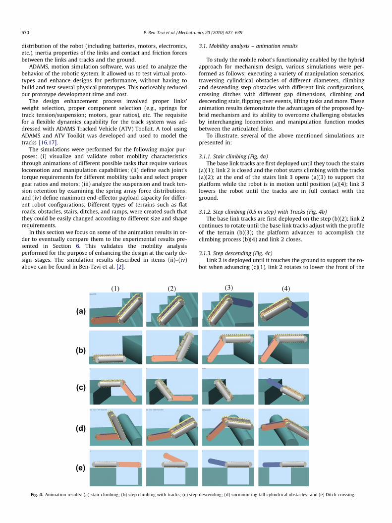
Fig. 4. Animation results: (a) stair climbing; (b) step climbing with tracks; (c) step
3.1. Mobility analysis – animation results
To study the mobile robot’s functionality enabled by the hybridapproach for mechanism design, various simulations were per-formed as follows: executing a variety of manipulation scenarios,traversing cylindrical obstacles of different diameters, climbingand descending step obstacles with different link configurations,crossing ditches with different gap dimensions, climbing anddescending stair, flipping over events, lifting tasks and more. Theseanimation results demonstrate the advantages of the proposed hy-brid mechanism and its ability to overcome challenging obstaclesby interchanging locomotion and manipulation function modesbetween the articulated links.
To illustrate, several of the above mentioned simulations arepresented in:
3.1.1. Stair climbing (Fig. 4a)The base link tracks are first deployed until they touch the stairs
(a)(1); link 2 is closed and the robot starts climbing with the tracks(a)(2); at the end of the stairs link 3 opens (a)(3) to support theplatform while the robot is in motion until position (a)(4); link 3lowers the robot until the tracks are in full contact with theground.
3.1.2. Step climbing (0.5 m step) with Tracks (Fig. 4b)The base link tracks are first deployed on the step (b)(2); link 2
continues to rotate until the base link tracks adjust with the profileof the terrain (b)(3); the platform advances to accomplish theclimbing process (b)(4) and link 2 closes.
3.1.3. Step descending (Fig. 4c)Link 2 is deployed until it touches the ground to support the ro-
bot when advancing (c)(1), link 2 rotates to lower the front of the
(3) (4)
descending; (d) surmounting tall cylindrical obstacles; and (e) Ditch crossing.

Signal from/to OCU
Signal to/from other subsystems
Controller
(a) Subsystem 1
Sensors Encoders
Central Wireless Comm. Module
Driver 1
Driver 2
M1
M2
Driver 3
Driver i
M3
Mi
Wireless Comm. Module
Controller
Driver 1
(b) Subsystem 2
Sensors
Encoders
Received/Sent Signal
Driver 2
M1
M2
Driver 3
Driver j
M3
Mj
Wireless Comm. Module
Controller
Driver 1
(c) Subsystem n
Sensors
Encoders
Driver 2
M1
M2
Driver 3
Driver k
M3
Mk
Wireless Comm. Module
Received/Sent Signal
Transceiver
Transceiver Transceiver
Transceiver
Fig. 5. Generalized on-board wireless communication layout.
P. Ben-Tzvi et al. / Mechatronics 20 (2010) 627–639 631
platform (c)(2); link 2 fully closes (c)(3); link 3 opens and the robotmoves forward (c)(4); link 3 rotates (until closed) to lower therobot.
3.1.4. Surmounting circular obstacles (Fig. 4d)The segmented nature of the robot’s structure allows it to sur-
mount cylindrical obstacles such as pipes and tree logs. The baselink tracks are deployed until they touch the obstacle (d)(1)–(2);at that point, the tracks start to propel the platform (d)(c) whileat the same time they continue their rotation about joint 1.
3.1.5. Ditch crossing (Fig. 4e)Since the robot can deploy link 2 from the front and link 3 from
the back (when all links are stowed), ditches can be traversedaccording to the following steps: from the back edge of the ditch,link 2 is deployed (e)(1); the robot advanced until the front andback are supported by the ditch edges (e)(2); link 2 closes and link3 opens from the back (e)(3); the robot continues its forward mo-tion until the COG passes the front edge of the ditch while link 3prevents from the robot from falling into the ditch as long as theCOG is before the front edge (e)(4).
4. On-board wireless sensor/actuator control hardwarearchitecture
Control architecture issues are the key to the design and con-struction of mobile robots, just as they are for any computer-con-trolled complex system that is subject to hard time constraints.Mobile robots need to constantly process large amounts of sensorydata in order to execute required controlled motions based on theoperator’s commands, or in autonomous operations, to build a rep-resentation of its environment and to determine meaningful ac-tions. The extent to which control architecture can support thisenormous processing task in a timely manner is affected signifi-cantly by the organization of information pathways within thearchitecture. The flow of information from sensing to action shouldbe maximized to provide minimal delay in responding to thedynamically changing environment.
A distributed processing architecture offers a number of advan-tages for coping with the significant design and implementationcomplexity inherent in sophisticated robot systems. First, it is often
cheaper and more resilient than alternative uniprocessor designs.More significantly, multiple processors offer the opportunity totake advantage of parallelism for improved throughput and forfault-tolerance.
This section presents the development of a new systematicapproach for a modular control hardware architecture that dra-matically increases the functionality of the hybrid mobile robotand provides operational fault-tolerance. This is done by provid-ing on-board distributed wireless communication between therobot’s subsystems and modules such as the actuators andsensors.
The proposed generalized wireless and modular control hard-ware architecture is depicted in Fig. 5. This scheme provides on-board wireless hardware control interfaces between several sub-systems constituting a given mechanical system and fulfils a listof general requirements as listed below. It also enables distributionof the electrical hardware independently (i.e., no wire connections)in a given robotic system’s links/segments (subsystems). In thecase of the hybrid mobile robot, the electrical hardware is situatedin two base link tracks and link 3. The electrical hardware associ-ated with the gripper mechanism is situated in link 3 (Fig. 3) andis not connected to any of the base link tracks via wires. This allowslink 3 to provide continuous rotation inside link 2. Similarly, thewireless data communication between the left and right base linktracks allow continuous rotation for link 2 between the base linktracks. Based on the design architecture of the hybrid mobile robotand the required functionality and specifications, the requirementsand the related solutions for the control architecture are analyzedas follows:
Requirements
(1) Provide modular mechanical and control system architec-ture: this provides operational fault-tolerance – namely, ifone of the robot subsystems (links) fails during operation,others will continue to operate with no interruption.
(2) Enable continuous rotation between robot links without: (i)physical wiring or cable loops (which limit the robot linksrange of motion) and (ii) slip ring connections (which greatlycomplicated the system design).
(3) Avoid direct RF communication between each robot seg-ment and the Operating Control Unit (OCU) in order to:

632 P. Ben-Tzvi et al. / Mechatronics 20 (2010) 627–639
� Eliminate stand-alone protruding antennas from eachsubsystem and thereby maintain the overall structure’ssymmetry.
� Prevent inconsistent data loss between the OCU and eachlink that may lead to de-synchronization between thetrack and link motions. Therefore, it is required that thedata pertaining to all robot links is received in one loca-tion on the robot (any of the links), and then transmittedand distributed to the other links wirelessly.
Solutions
(1) Provide independent power source for each robot link/sub-system (using Li-Ion battery packs).
(2) Enable on-board wireless communication between robotlinks/subsystems:
� Ensures that data pertaining to the robot segments isreceived in one location and then distributed to othersubsystems.
OCU: RF data signal (900 MHz)
Wireless 900 MHz
Left base link 1 track
W
irel
ess
2.4
GH
z
M
M = Motor
M
M M
Wireless 2.4 GHz
Link 3 Link 2
Right base link 1 track
Fig. 6. On-board wireless communication layout for the HMR.
4.1. Generalized on-board wireless communication layout
Fig. 5 shows a mechanical system with n subsystems. A centralwireless communication module is embedded in any of the n sub-systems (e.g., Fig. 5a shows the central communication module insubsystem 1) for communication with the OCU, while each of theremaining subsystems contains a wireless communication modulefor inter-segmental on-board wireless communication. This, alongwith independent power source in each subsystem, eliminates theneed for physical wiring between the rotating or translating sub-systems. This enables the subsystems to provide continuous rota-tion or translation about their respective joints and prevent anyrestriction to their range of motion. In the case of the HMR, this en-ables links 1, 2 and 3 and the gripper mechanism to provide contin-uous rotation about their respective joints.
The data transmitted by the OCU is received by a central wire-less communication transceiver module that can be situated in anyof the n subsystems as shown in Fig. 5a. This wireless communica-tion module communicates with the local controller that controlsthe electronics (motors and associated drivers, sensors, etc.) in thatsubsystem while at the same time sends data pertaining to theother subsystems to a separate wireless transceiver module in awire connection. This data is then transmitted wirelessly to theremaining (n-1) wireless transceiver modules (subsystem 2-sub-system n), thus providing on-board wireless data communicationamong robot subsystems.
This hardware architecture provides extendibility in terms ofthe number of subsystems that can be added or removed in orderto constitute a given robotic system. It also provides expandabil-ity in the subsystem level – namely, the number of components(e.g., drivers and motors) in each subsystem can be expandeddepending on the required number of dof’s. It should be takeninto consideration however that both types of expandabilitymay be limited by the number of available wireless communica-tion ports in the central wireless module as well as the numberof drivers that could be interfaced in each subsystem’s on-boardcontroller.
Based on this hardware architecture, fault-tolerance is achievedsince each subsystem is independent of the other. For instance, ifsubsystem 2 fails, the others can continue to operate. This maynot work if the subsystem that contained the central wireless com-munication module fails. In order to solve this problem, a centralwireless module can be embedded in each of the subsystems andtriggered in a predetermined sequence in case their neighboringsubsystem failed.
4.2. Case study – wireless hardware architecture for the hybrid mobilerobot using RF communication
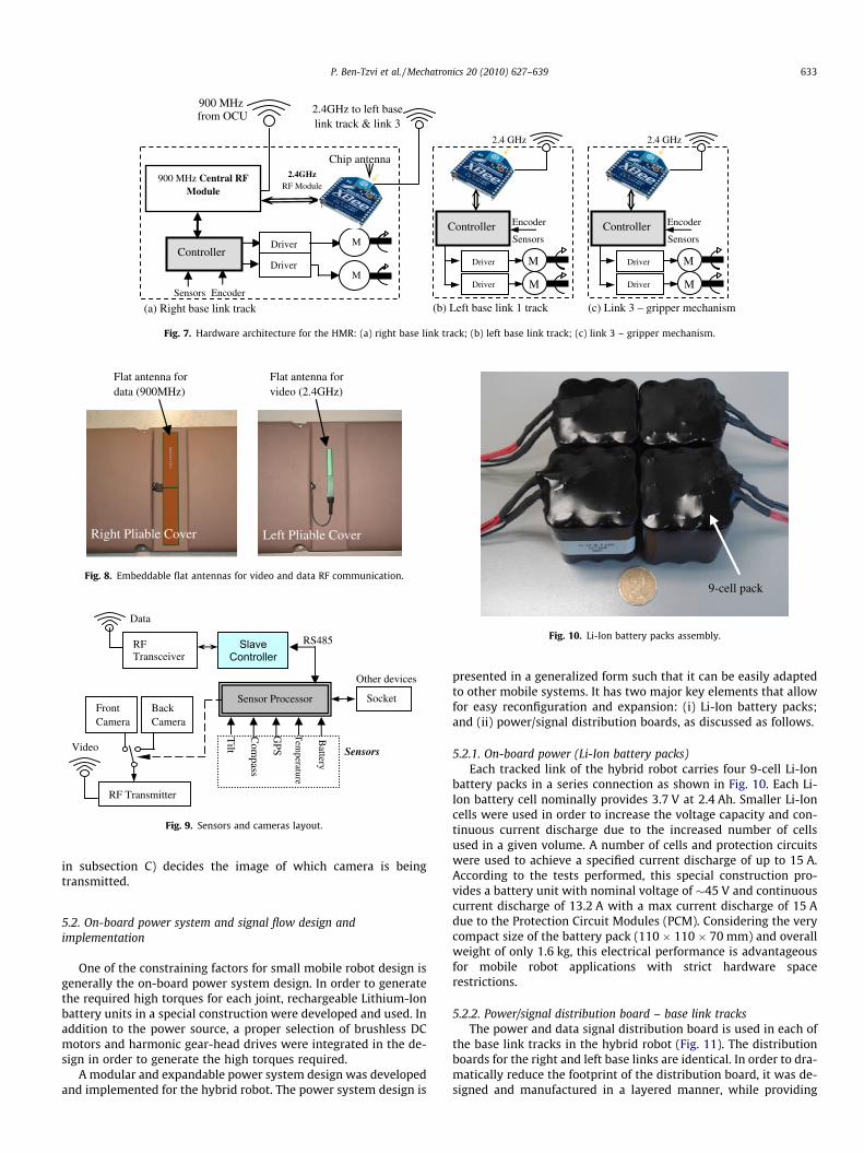
To experimentally demonstrate the validity of the control hard-ware architecture provided in Fig. 5, it was implemented as a casestudy on the hybrid mobile robot using RF communication in themanner shown in Fig. 6. In this case, the OCU includes a900 MHz RF transceiver. The data transmitted by the stand aloneRF transceiver on the OCU is received by an RF transceiver that issituated in the right base link track as shown in Fig. 7a. This RFtransceiver communicates with the local controller that controlsthe electronics (motors and associated drivers, sensors, etc.) inthe right base link track while at the same time sends data pertain-ing to the other segments (left base link track and link 3) to a2.4 GHz RF transceiver in a wire connection. This data is thentransmitted wirelessly to two other 2.4 GHz RF transceiver – onefor the left base link track and the other for link 3 (Figs. 7b andc), thus providing on-board wireless RF data communicationamong robot joints.
The RF modules for on-board wireless communication areadvantageous in several ways: (i) they eliminate the need for aprotruding antenna for each link segment of the robot since it isavailable with a PCB chip antenna (Fig. 8a) and (ii) they have differ-ent operating frequency (2.4 GHz) than the primary RF module.Due to the short and fixed distances between the robot’s links/sub-systems, low-power on-board RF modules between the left andright base link 1 tracks and link 3 were used without any commu-nication interferences between the subsystems.
Protruding antennas are avoided by using custom designed flatantennas (Nearson Global Antenna Solutions) and embeddingthem into the robot side covers for wireless video communicationand wireless data communication as shown in Figs. 3 and 8.
5. Electrical hardware architecture
5.1. Controllers, drivers, sensors and cameras layout
Each motor in the base link tracks is driven by a driver, whichacts as a motor controller to provide position and speed control.Signals from encoders attached to the rear shaft of each motorare sent to the drivers as feedback. The sensors which the robotis equipped with are: a tilt sensor; thermometer, GPS, three-axiscompass (inclinometer) and battery-voltage monitor (Fig. 9). Asshown in Fig. 3, there are two embedded cameras located in thefront and back of the left base link track, which provide visualinformation to the OCU operator on the robot’s surroundings.A transmitter is used to transmit the video signals to the OCU. Aswitch controlled by the sensor processor (described in more detail
Controller
Driver
(b) Left base link 1 track
Sensors
Encoder
2.4 GHz
Driver
M
M
Controller
Driver
(c) Link 3 – gripper mechanism
Sensors
Encoder
2.4 GHz
Driver
M
M
900 MHzfrom OCU
2.4GHz to left base link track & link 3
Controller Driver M
(a) Right base link trackSensors Encoder
900 MHz Central RF Module
Driver M
2.4GHz RF Module
Chip antenna
Fig. 7. Hardware architecture for the HMR: (a) right base link track; (b) left base link track; (c) link 3 – gripper mechanism.
Right Pliable Cover Left Pliable Cover
Flat antenna for video (2.4GHz)
Flat antenna for data (900MHz)
Fig. 8. Embeddable flat antennas for video and data RF communication.
Sensor Processor
RF Transceiver
Socket
Tilt
Com
pass
GPS
Battery
Tem
perature
Other devices
RF Transmitter
Front Camera
Video
RS485 Slave Controller
Sensors
BackCamera
Data
Fig. 9. Sensors and cameras layout.
9-cell pack
Fig. 10. Li-Ion battery packs assembly.
P. Ben-Tzvi et al. / Mechatronics 20 (2010) 627–639 633
in subsection C) decides the image of which camera is beingtransmitted.
5.2. On-board power system and signal flow design andimplementation
One of the constraining factors for small mobile robot design isgenerally the on-board power system design. In order to generatethe required high torques for each joint, rechargeable Lithium-Ionbattery units in a special construction were developed and used. Inaddition to the power source, a proper selection of brushless DCmotors and harmonic gear-head drives were integrated in the de-sign in order to generate the high torques required.
A modular and expandable power system design was developedand implemented for the hybrid robot. The power system design is
presented in a generalized form such that it can be easily adaptedto other mobile systems. It has two major key elements that allowfor easy reconfiguration and expansion: (i) Li-Ion battery packs;and (ii) power/signal distribution boards, as discussed as follows.
5.2.1. On-board power (Li-Ion battery packs)Each tracked link of the hybrid robot carries four 9-cell Li-Ion
battery packs in a series connection as shown in Fig. 10. Each Li-Ion battery cell nominally provides 3.7 V at 2.4 Ah. Smaller Li-Ioncells were used in order to increase the voltage capacity and con-tinuous current discharge due to the increased number of cellsused in a given volume. A number of cells and protection circuitswere used to achieve a specified current discharge of up to 15 A.According to the tests performed, this special construction pro-vides a battery unit with nominal voltage of �45 V and continuouscurrent discharge of 13.2 A with a max current discharge of 15 Adue to the Protection Circuit Modules (PCM). Considering the verycompact size of the battery pack (110 � 110 � 70 mm) and overallweight of only 1.6 kg, this electrical performance is advantageousfor mobile robot applications with strict hardware spacerestrictions.
5.2.2. Power/signal distribution board – base link tracksThe power and data signal distribution board is used in each of
the base link tracks in the hybrid robot (Fig. 11). The distributionboards for the right and left base links are identical. In order to dra-matically reduce the footprint of the distribution board, it was de-signed and manufactured in a layered manner, while providing

XBee 2.4 GHz RF Module
Four video inputs + video quad
2 1 34Quad
RS485 Input
RS485 Output
Fig. 11. Power/signal distribution board for base link tracks.
Digital Inclinometer
RCM3400 RabbitCore μ Processor
RS485 Interface to Distribution Board
Additional RS485 Inputs to interface more devices
Fig. 13. Sensor processor board.
900 MHz RF Transceiver (XTend Modem)
OCU Battery Charger
634 P. Ben-Tzvi et al. / Mechatronics 20 (2010) 627–639
sufficient input/output interfaces for a large number of on-boarddevices as well as attachable devices for the mobile robot, suchas LED lights (front and back), cameras (front and back), and vari-ous sensors. One of the board’s purposes was to take the powerprovided by the battery charging boards and distribute it to thevarious on-board instruments. Power from the battery chargingboards is funnelled through several DC–DC converters which regu-late the voltage up or down as necessary before being distributedto the on-board instruments.
5.2.3. Gripper mechanism power/signal distribution board andhardware architecture
As shown in Fig. 12, the analog RabbitCore provides a processorand analog input subsystem for OEMs to integrate into the customdesign power/signal distribution board for the gripper mechanism.Link 3 distribution board is also equipped with integrated DC–DCmodules in order to provide the required DC voltage levels foron-board modules.
The gripper wrist is driven by an external motion controller thatcan perform the following tasks: velocity control with highrequirements on synchronous operation and minimal torque fluc-tuations. A PI controller ensures observance of the target velocities;velocity profiles such as ramp, triangular or trapezoidal move-ments can be realized; and positioning mode.
5.3. Sensor processor board
The sensor processor PCB design shown in Fig. 13 is equippedwith a digital compass used for precision robot inclination mea-surements. The compass includes a MEMS accelerometer for a
RCM3400 RabbitCore μ P
Signals to GripperSignals to Wrist
12V DC Power
2.4 GHz RF Module
Fig. 12. Power/signal distribution board for gripper mechanism.
horizontal three-axis, tilt compensated precision compass for per-formance up to a ±60� tilt range.
The Rabbit Core l Processor is the same as the one embedded inlink 3 distribution board and is used to process the data receivedfrom the various sensors in the mobile robot. Each of the DC-DCmodules regulates the 12 V input into the board to generaterequired voltage level for onboard instruments. The PCB wasdesigned with additional RS485 inputs in order to interface addi-tional sensors/devices as necessary.
5.4. Robot DOF and Operator Control Unit (OCU)
The OCU for the current mobile robot prototype, as shown inFig. 14, consists of two control sticks (LS-731, from Logosol), con-troller LS991 with text monitor, 900 MHz RF data transceiver(XTend modem, from Maxtream), and 12 V battery and batterycharger. The OCU for this prototype currently does not include a vi-deo monitor and video/audio RF receiver.
The two control sticks in the remote OCU are used by the oper-ator in order to remotely coordinate the robot degrees of freedomwhen generating the motions required for a given task. The
+x
+y
-y
-x
θ
+x’
-x’ -y’
+y’
+x
+y
-y
High speed (H) button
Low speed (L)
+z -z
-x
(a) (b)
Control Stick # 1
Control Stick # 2
Controller LS991 with Text Monitor
Fig. 14. Operator Control Unit (OCU) and robot DOF: (a) control stick # 1 (C1)motions layout and (b) control stick # 2 (C2) motions layout.

P. Ben-Tzvi et al. / Mechatronics 20 (2010) 627–639 635
forward, backward, right turn and left turn motions of the base linktracks are controlled by an up, down, right and left movement ofthe first control sticks (C1). The second control stick (C2) is usedto control links 2 and 3 dof’s. A right movement of C2 control stickwill generate a clockwise (CW) independent motion of link 2 whilea left movement of the control stick will generate a counterclock-wise (CCW) independent motion of link 2. Similarly, an up anddown movement of the second control stick will generate an inde-pendent CW and CCW motion of link 3, respectively. Furthermore,four diagonal movements of the second control stick (i.e., +x0, �x0,+y0, �y0 directions as shown in Fig. 14) will generate simultaneousmotions of links 2 and 3 as follows:
(i) Movement of C2 in the +x0 direction will move links 2 and 3simultaneously both in the CW direction.
(ii) Movement of C2in the �x0 direction will move links 2 and 3simultaneously both in the CCW direction.
(iii) Movement of C2 in the +y0 direction will move links 2 and 3simultaneously in the CW and CCW directions, respectively.
(iv) Movement of C2 in the �y0 direction will move links 2 and 3simultaneously in the CCW and CW directions, respectively.
The CW and CCW wrist motions of the gripper mechanism aswell as the open and close motions of the gripper jaws are gener-ated with a separate mode of the first control stick.
The first and second control sticks can be operated simulta-neously by the operator in order to provide simultaneous motionsof the tracks along with different motion combinations of links 2and 3, as explained above.
Fig. 14 shows the top view of Control Stick # 1 (C1) with twoswitch-able modes as follows: (i) track motions – Mode 1 (M1);and (ii) gripper mechanism motions – Mode 2 (M2). Control Stick# 2 (C2) has two coordinate systems x–y and x0–y0 for link 2 and3 motions. The control angle h in C2 provides speed variability toeach of the links 2 and 3 when operated simultaneously.
6. Experimental setup and results
Following the integration of the physical prototype shown inFig. 15, a series of extensive experimental tests were performedto assess the robot’s mobility, manipulability, and durability char-acteristics. Throughout the experiments, the robot was remotelycontrolled by an operator using the OCU as described in Section 5.4.The obstacle course consisted of various test rigs including man-made and natural obstructions as a representative subset of the ro-bot’s possible hindrances to cross country movement related topertinent applications, such as: search and rescue, reconnaissance,surveillance, hazardous site inspections, military and police mis-sions. The integrated wireless control architecture provided themobile robot with the ability to generate continuous rotations to
Embedded flat data RF antenna
(a) Embeded flat Video RF antenna
Fig. 15. Mobile robot prototype: (a) stowed-links configuration mod
each of its links without limiting their range of motion. This isone of the key features that significantly enhanced the mobile ro-bot’s functionality by being able to deploy the base link tracks,links 2 and 3 independently from the front and the back with var-ious link sequences. The other important key feature is the overallgeometrically symmetric design (in stowed-links configuration –Fig 15a) that allows the platform to invert itself and continue tooperate with no need of special purpose active means to re-invertit.
6.1. Robot mobility
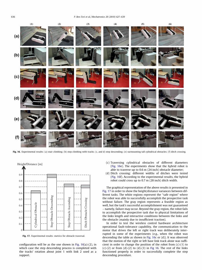
The proposed design of the hybrid mobile robot was tested insimulations in Section 3. The simulations demonstrated a compactarticulated hybrid mechanism that is able to exhibit new mobility,manipulation, and compounded locomotion and manipulationcapabilities. The experimental results in this section demonstratethe validity of the proposed design paradigm hypothesis as wellas the validity of the simulations. The experimental results shownin Fig. 16 accurately coincide with the simulation results shown inFig. 4. The simulations are claimed to be valid by showing that thefunctionalities of the virtual prototype robot shown through simu-lations can be replicated with the actual physical prototype in real-world environments.
Different types of terrains such as flat roads, obstacles, stairs,ditches, ruble piles and ramps, were tested with different shapesand sizes. These types of obstacles are typical challenges mobile ro-bots face during applications for search and rescue, reconnais-sance, military operations, hazardous site inspections, etc. Byproviding the new locomotion and manipulation capabilities withthe HMR system, the functionality performance of mobile robots inthose applications is expected to be dramatically improved.
Some of the challenging tests that were used in order to test thehybrid robot are as follows (the experimental results are also sum-marized in a graphical format in Fig. 17):
(a) Climb and descend stairs (Fig. 16a) with different materials(wood, metal, concrete, plastic plastered, etc.), different stairriser and run sizes, and inclinations (50� stair slope);
(b) Step obstacle climbing and descending (Fig. 16b and c): dif-ferent heights of step obstacles were tested. According to theexperimental results, the HMR could climb steps up to 0.7 m(28 inch) height and descend even greater heights of 0.85 m.This can be achieved since during descending, link 3 can beextended in addition to link 2 to support the front of therobot while descending as shown in Fig. 16d. It should benoted however that in this case a ‘‘hard landing” of the frontend of the robot on the ground occurs. The transitionbetween configurations (c)-(3) and (c)-(4) may cause flip-ping over of the robot. But in this case, the new robot
Pliable side
covers
(b)
e and (b) open configuration mode (all other covers removed).
(a)
(b)
(c)
(d)
(e)
(f)
(1) (2) (3) (4) (5) (6)
Fig. 16. Experimental results: (a) stair climbing; (b) step climbing with tracks; (c, and d) step descending; (e) surmounting tall cylindrical obstacles; (f) ditch crossing.
0
0.1
0.3
0.2
0.4
0.5
0.7
0.6
0.8
Height/Distance [m]
0.9
D
itch
Obs
tacl
e C
ross
ing
St
ep O
bsta
cle
Asc
endi
ng
St
ep O
bsta
cle
Des
cend
ing
C
ylin
dric
al O
bsta
cle
Fig. 17. Experimental results: metrics for obstacle traversal.
636 P. Ben-Tzvi et al. / Mechatronics 20 (2010) 627–639
configuration will be as the one shown in Fig. 16(a)-(2), inwhich case the step descending process is completed withthe tracks’ rotation about joint 1 with link 2 used as asupport.
(c) Traversing cylindrical obstacles of different diameters(Fig. 16e). The experiments show that the hybrid robot isable to traverse up to 0.6 m (24 inch) obstacle diameter;
(d) Ditch crossing: different widths of ditches were tested(Fig. 16f). According to the experimental results, the hybridrobot could cross up to 0.7 m (28 inch) ditch width.
The graphical representation of the above results is presented inFig. 17 in order to show the height/distance variances between dif-ferent tasks. The white regions represent the ‘‘safe region” wherethe robot was able to successfully accomplish the prospective taskwithout failure. The gray region represents a feasible region aswell, but the task’s successful accomplishment was not guaranteed– namely, failure may occur. Beyond the gray region, the robot failsto accomplish the prospective task due to physical limitations ofthe links length and interactive conditions between the links andthe obstacle (mainly due to insufficient traction).
In order to test the wireless control hardware architectureoperational fault-tolerance capability, the communication to themotor that drives the left or right track was deliberately inter-rupted in some of the experiments (e.g., when the robot wasdescending the table as shown in Fig. 16c or (d)). It was observedthat the motion of the right or left base link track alone was suffi-cient in order to change the position of the robot from (c)-(1) to(c)-(2) or from (d)-(2) to (d)-(3) in Fig 16. The rest of the linksfunctioned properly in order to successfully complete the stepdescending procedure.

(c)(b)(a)
(e)(d) (f)
Object
Fig. 18. Simultaneous climbing and manipulation.
P. Ben-Tzvi et al. / Mechatronics 20 (2010) 627–639 637
6.2. Simultaneous locomotion and manipulation
The various climbing and descending tasks presented in theprevious section can be incorporated simultaneously with manip-ulation of objects. Various experiments were performed in order todemonstrate this capability, which is a direct outcome of the hy-brid nature of the platform and manipulator arm and their abilityto be interchangeable in their roles and provide both functional-ities simultaneously.
The following locomotion tasks were successfully experimentedwhile simultaneously manipulating an object:
(1) Ascending and descending of stairs.(2) Traversing tall cylindrical obstacles.(3) Crossing ditches.(4) Climbing and descending step obstacles with various motion
configurations.
In order to demonstrate this capability, Sections 6.2.1 and 6.2.2present two cases where the robot climbed and descended a 0.7 mstep obstacle while holding an object.
6.2.1. Simultaneous obstacle climbing and manipulationFig. 18 demonstrates the hybrid mobile robot’s capability to
pick up an object, and climb a step obstacle with the base linktracks while holding the object with the gripper mechanism. Thisstep climbing is similar to the one shown in Fig. 16b except thatlink 3 remains deployed in order to manipulate the objectsimultaneously.
(a) (b)
(e) (f)
Object
Fig. 19. Simultaneous descen
6.2.2. Simultaneous obstacle descending and manipulationFig. 19 shows the hybrid mobile robot’s configuration steps in
order to descend the step obstacle with the base link tracks whileholding the object with the gripper mechanism. The motion se-quence of the robot links required to descend the obstacle is sim-ilar to the one presented in Fig. 16d with the exception that link 3remains deployed in order to manipulate the object at the sametime.
6.3. Configurations of mobility for traversing rubble piles
Fig. 20 depicts a simulated earthquake scenario in an officebuilding. The robot’s task was to traverse a rubble pile in its wayto access and reach a target and search for survivors. This scenariodemonstrates the hybrid robot’s capability to easily climb over therubble pile and return by using a combination of the various mobil-ity capabilities presented thus far. These mainly include climbingand descending with the aid the base link tracks, links 2 and 3.Some of the configuration steps in Fig. 20 also show how the plat-form effectively utilizes its ability to adjust the level of traction toeffectively traverse the rubble pile.
6.4. End-effector payload capacity for manipulation
The following experiments demonstrate the dramatically in-creased actuator strength capacity for manipulation purposesdue to the articulated hybrid mechanical structure. The end-effector load capacity for different manipulation configurationswas also evaluated. The graph shown in Fig. 21 describes the load
(d)(c)
(g) (h)
ding and manipulation.
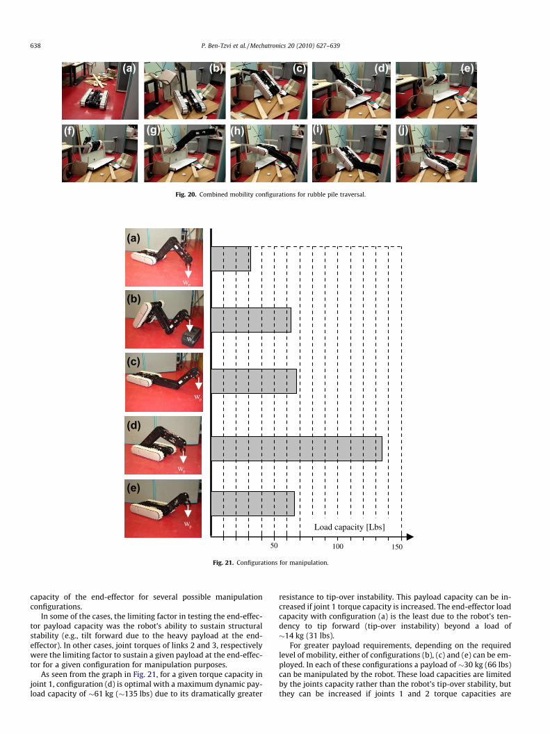
(a) (b) (e) (d)
(f) (g) (h) (i) (j)
(c)
Fig. 20. Combined mobility configurations for rubble pile traversal.
(a)
(e)
(d)
(c)
(b)
50 100 150
w
w
w
w
w Load capacity [Lbs]
p
p
p
p
p
Fig. 21. Configurations for manipulation.
638 P. Ben-Tzvi et al. / Mechatronics 20 (2010) 627–639
capacity of the end-effector for several possible manipulationconfigurations.
In some of the cases, the limiting factor in testing the end-effec-tor payload capacity was the robot’s ability to sustain structuralstability (e.g., tilt forward due to the heavy payload at the end-effector). In other cases, joint torques of links 2 and 3, respectivelywere the limiting factor to sustain a given payload at the end-effec-tor for a given configuration for manipulation purposes.
As seen from the graph in Fig. 21, for a given torque capacity injoint 1, configuration (d) is optimal with a maximum dynamic pay-load capacity of �61 kg (�135 lbs) due to its dramatically greater
resistance to tip-over instability. This payload capacity can be in-creased if joint 1 torque capacity is increased. The end-effector loadcapacity with configuration (a) is the least due to the robot’s ten-dency to tip forward (tip-over instability) beyond a load of�14 kg (31 lbs).
For greater payload requirements, depending on the requiredlevel of mobility, either of configurations (b), (c) and (e) can be em-ployed. In each of these configurations a payload of �30 kg (66 lbs)can be manipulated by the robot. These load capacities are limitedby the joints capacity rather than the robot’s tip-over stability, butthey can be increased if joints 1 and 2 torque capacities are

P. Ben-Tzvi et al. / Mechatronics 20 (2010) 627–639 639
increased. This result is a direct consequence of the new design –namely, the hybrid nature of the platform and manipulator armand their ability to be interchangeable in their roles.
7. Conclusions
This paper presented the complete development and experi-mental results of a new mobile robot system that can be used ina vast variety of pertinent applications, such as: search and rescuemissions, reconnaissance, inspection, surveillance, planetaryexploration, and police and military tasks. This is by the virtue ofits ability to provide new locomotion and manipulation capabili-ties that greatly help to overcome challenging obstacles that aretypically encountered in those applications. The new mobile robotdesign was based on hybridization of the mobile platform andmanipulator arm mechanisms as one entity for robot locomotionas well as manipulation. As part of the development, we presentednew distributed wireless electrical/control hardware architecturefor mobile robots, which was implemented in the new articulatedmobile robot design. The design, construction and experimentalvalidation of the novel control hardware architecture for on-boardinter-segmental wireless communication among the robot’s linkswere successfully accomplished. Various other mobile robot con-figuration, where similar mechanical/control hardware designcharacteristics are required, can adopt this control hardware archi-tecture. It provides a wireless communication network betweensubsystems of a given mechanical system in order to avoid anywire connections. This approach, along with expandable indepen-dent power source for each subsystem, resulted in modular controlhardware architecture that also provided operational fault-tolerance.
The hybrid mobile robot’s simulated locomotion and manipula-tion modes, such as those shown in Figs. 2 and 4 were experimen-tally validated with a physical prototype, as was shown in Fig. 16.The new functions of locomotion, manipulation and hybrid loco-motion and manipulation have been utilized to demonstrate alarge variety of unique and very challenging practical tasks the mo-bile robot was able to perform. Some of the tasks include: travers-ing tall cylindrical obstacles (up to 0.6 m); climbing anddescending stairs (variety of slops, materials, and sizes); climbingand descending tall obstacles (up to 0.7 m); crossing ditches (upto 0.7 m); lifting payloads of up to 61 kg (135 lbs) in manipulationmode and carrying payloads of up to 187 kg (410 lbs) in locomo-tion mode; and tasks that require simultaneous manipulationand climbing/descending of obstacles. The hybrid mobile robot’sversatile and agile functionality has also shown the ability to tra-verse rubble piles, which also demonstrate the durability charac-teristics of the new mobile robot design. The presented newlocomotion, manipulation and hybrid functionality modes can beused to overcome pertinent locomotion and manipulation chal-lenges in a wide range of practical applications, such as searchand rescue missions, earthquake sites, reconnaissance, planetaryexploration, military and police operations, etc. Video clipsshowing the robot performing the functionalities described in theexperiments section and various other tasks are available onlinein the following link: http://www.seas.gwu.edu/~bentzvi/HMR/HMR_Videos.
As part of the future work, we plan on developing a new OCUthat includes a video monitor and video/audio RF receiver so thatthe camera images can be communicated and displayed for outof sight remote operations. We will evaluate the technological as-pects of such implementation and the practicality of the camera
position on the robot and controllability of the vehicle (out of sightand based on the camera images only).
Acknowledgments
This work was partially supported by Natural Sciences andEngineering Research Council of Canada (NSERC), and EngineeringServices Inc.
References
[1] Angeles J. An innovative drive for wheeled mobile robots. IEEE/ASME TransMech 2005;10(1):43–9.
[2] Ben-Tzvi P, Goldenberg AA, Zu JW. Design, simulations and optimization of atracked mobile robot manipulator with hybrid locomotion and manipulationcapabilities. In: Proceedings of the 2008 IEEE international conference onrobotics and automation (ICRA’08), Pasadena, California, May 19–23, 2008.
[3] Ben-Tzvi P. Hybrid Mobile Robot System: Interchanging Locomotion andManipulation, Ph.D. dissertation, Dept. of Mechanical and Industrial Eng., Univ.of Toronto, Ontario, Canada; 2008.
[4] Ben-Tzvi P, Raoufi C, Goldenberg AA, Zu JW. Virtual prototype developmentand simulations of a tracked hybrid mobile robot. In: Proceedings of MSC.Software 2007 Virtual Product Development Conference, Detroit, Michigan,October 10–12, 2007.
[5] Ben-Tzvi P, Goldenberg A, Zu JW. Design and analysis of a hybrid mobile robotmechanism with compounded locomotion and manipulation capability. JMech Des 2008;130(7):1–13.
[6] Carlson J, Murphy RR. How UGVs physically fail in the field. IEEE TransRobotics 2005;21(3):423–37.
[7] Clark JE, Cham JG, Bailey SA, Froehlich EM, Nahata PK, Full RJ, et al. Biomimeticdesign and fabrication of a hexapedal running robot. In: Proceedings of 2001IEEE international conference on robotics and automation, vol. 4; 2001. p.3643–49.
[8] Costo S, Molfino R. A new robotic unit for onboard airplanes bomb disposal. In:35th International symposium on robotics ISR 2004, Paris; 2004. p. 23–6.
[9] Foster-Miller, TALON Mobile Robot. <http://www.foster-miller.com/lemming.htm>.
[10] Full RJ, Koditschek DE. Neuromechanical hypotheses of legged locomotion onland. J Exp Biol 1999;202:3325–32.
[11] Goldenberg AA, Lin J. Variable configuration articulated tracked vehicle. USPatent #7493,976; 2009.
[12] Guarnieri M, Debenest P, Inoh T, Fukushima E, Hirose S. Helios VII: a newvehicle for disaster response, mechanical design and basic experiments. AdvRobotics 2005;19(8):901–27.
[13] Hirose S, Fukushima EF, Damoto R, Nakamoto H. Design of terrain adaptiveversatile crawler vehicle HELIOS-VI. In: Proceedings of IEEE/RSJ internationalconference on intelligent robots and systems, Hawaii; 2001. p. 1540–5.
[14] Iwamoto T, Yamamoto H. Mechanical design of variable configuration trackedvehicle. Trans ASME – J Mech Des 1990;112:289–94.
[15] Kennedy B, Agazarian H, Cheng Y, Garrett HG, Huntsberger T, Magnone L, et al.LEMUR: legged excursion mechanical utility rover. Auton Robots2001;11(11):201–5.
[16] Malik SM, Lin J, Goldenberg AA. Virtual prototyping for conceptual design of atracked mobile robot. In: Canadian conference on electrical and computerengineering, Ottawa, Ontario, Canada; 2006.
[17] Malik SM. Virtual prototyping for conceptual design of tracked mobile robots,M.S. thesis, Univ. of Toronto, Ontario, Canada; 2006.
[18] Michaud F, et al. Co-design of AZIMUT, a multi-modal robotic platform. In:ASME 2003 design engineering technology conferences and computers andinformation in engineering conference, Chicago, IL, USA, September 2–6, 2003.
[19] Munkeby S, Jones D, Bugg G, Smith K. Applications for the MATILDA roboticplatform. In: Proceedings of SPIE – unmanned ground vehicle technology IV,vol. 4715; 2002. p. 206–13.
[20] Purvis JW, Klarer PR. RATLER: robotic all terrain lunar exploration rover. In:Proceedings of sixth annual space operations, applications and researchsymposium, Johnson Space Center, Houston, TX; 1992. p. 174–9.
[21] Saranli U, Buehler M, Koditschek DE. RHex: a simple and highly mobilehexapod robot. Int J Robot Res 2001;20(7):616–31.
[22] Wang D, Low CB. Modelling and analysis of skidding and slipping in wheeledmobile robots: control design perspective. IEEE Trans Robot2008;24(3):676–87.
[23] White JR, Sunagawa T, Nakajima T. Hazardous-duty robots – experiences andneeds. In: Proceedings of IEEE/RSJ international workshop on intelligent robotsand systems ’89 (IROS ’89); 1989.p. 262–7.
[24] Yamauchi B. PackBot: a versatile platform for military robotics. In: Proceedingsof SPIE – unmanned ground vehicle technology VI, vol. 5422, Orlando, FL, April2004. p. 228–37.