robotic turret - cal poly
TRANSCRIPT

Robotic Turret
Project Report ME-430 Fall 2011
Daniel Romero ([email protected])
Matt Martelle ([email protected])
Scott Mullens ([email protected])
Rachel Diamant ([email protected])
Advisor: Sarah Harding
Sponsor: Synbotics, San Luis Obispo, CA
Robotic Turret Final Design Report
i
Table of Contents Chapter 1: Introduction ................................................................................................................................ 2
1.1 Problem Statement ............................................................................................................................. 2
1.2 Requirements & Specifications ........................................................................................................... 2
Chapter 2: Background ................................................................................................................................. 3
2.1 Turrets ................................................................................................................................................. 3
2.2 Platforms ............................................................................................................................................. 4
2.3 Electronics ........................................................................................................................................... 6
Chapter 3: Concept ....................................................................................................................................... 7
3.1 Concept Generation ............................................................................................................................ 7
Physical System ..................................................................................................................................... 7
Electrical System ................................................................................................................................... 9
3.2 Concept Selection ............................................................................................................................. 10
Gun Mount .......................................................................................................................................... 10
Motors ................................................................................................................................................. 10
Camera Isolation ................................................................................................................................. 11
Bearings ............................................................................................................................................... 12
Camera-laser Range-finder (CLR) ........................................................................................................ 13
Microstrain IMU .................................................................................................................................. 14
Foxconn D52S Intel Atom D525 .......................................................................................................... 14
ARM7 Development Board ................................................................................................................. 14
Dual MC33926 Motor Driver Boards .................................................................................................. 15
Basic Software and Electronics Structure ........................................................................................... 15
Chapter 4: Final Design Description ............................................................................................................ 16
4.1 Overall Description ............................................................................................................................ 16
4.2 Detailed Design Descriptions ............................................................................................................ 17
Y-Frame ............................................................................................................................................... 17
Vertical Axis Subsystem ...................................................................................................................... 18
Cradle Assembly .................................................................................................................................. 18
Motor Selection .................................................................................................................................. 24
Camera Turret ..................................................................................................................................... 25
Electronics ........................................................................................................................................... 27

Robotic Turret Final Design Report
ii
Programming ....................................................................................................................................... 28
4.3 System Dynamics Analysis ............................................................................................................... 28
4.4 Cost Analysis .................................................................................................................................... 29
Chapter 5: Project Timing ........................................................................................................................... 31
5.1 Manufacturing Plan ........................................................................................................................... 31
5.2 Overall Project Timing ...................................................................................................................... 32
5.3 General Testing Scheme ................................................................................................................... 32
Chapter 6: Product Realization ................................................................................................................... 34
6.1 Manufacturing Process ...................................................................................................................... 34
Cradle .................................................................................................................................................. 34
Y-Frame ............................................................................................................................................... 35
Base Structure ..................................................................................................................................... 36
Electrical System ................................................................................................................................. 37
6.2 Differences in Prototype from Design .............................................................................................. 39
6.3 Recommendations for Manufacturing............................................................................................... 42
Chapter 7: Design Verification ................................................................................................................... 43
Test Descriptions ..................................................................................................................................... 43
Detailed Results ...................................................................................................................................... 45
Chapter 8: Conclusion ................................................................................................................................. 46
Appendices .................................................................................................................................................. 47
Appendix A – Quality Function Deployment Chart (QFD) ....................................................................... 48
Appendix B – Gantt Chart ....................................................................................................................... 49
Appendix C – Cost Analysis ..................................................................................................................... 50
Appendix D – DVP&R .............................................................................................................................. 52
Appendix F .............................................................................................................................................. 54
Appendix G .............................................................................................................................................. 55
Appendix H .............................................................................................................................................. 56
Appendix I ............................................................................................................................................... 59
Appendix J ............................................................................................................................................... 67
Appendix K .............................................................................................................................................. 69

Robotic Turret Final Design Report
iii
List of Figures Figure 1 Paintball sentry prototype (paintballsentry.com) ........................................................................................... 3 Figure 2 Super aEgis II, made by DoDAMM and used by South Korea. (gizmag.com) (CCTV News) ........................ 3 Figure 3 ThinkGeek’s USB Rocket Launcher (thinkgeek.com) ..................................................................................... 4 Figure 4 Dagu “Wild Thumper” 6WD All Terrain Chassis (pololu.com) ..................................................................... 4 Figure 5 DFRobot 4WD Arduino Mobile Platform. (DFRobot.com) ............................................................................ 5 Figure 6 concept design sketch by Rachel Diamant ...................................................................................................... 7 Figure 7 concept design sketch by Daniel Romero ....................................................................................................... 8 Figure 8 Concept Design Sketch ................................................................................................................................... 8 Figure 9 Motors ........................................................................................................................................................... 10 Figure 10 Velocity vs. Time of turret ........................................................................................................................... 11 Figure 11 Slew Bearing ............................................................................................................................................... 12 Figure 12 Physical Turret Model ................................................................................................................................ 13 Figure 13 Laser ........................................................................................................................................................... 13 Figure 14: Camera ...................................................................................................................................................... 14 Figure 15 IMU ............................................................................................................................................................. 14 Figure 16 Foxconn D52S Intel Atom D525 ................................................................................................................. 14 Figure 17 Dual MC33926 Motor Driver Boards ........................................................................................................ 15 Figure 18 SolidWorks Model of final design ................................................................................................................ 16 Figure 19 Y-frame exploded view ................................................................................................................................ 17 Figure 20 Vertical subsystem exploded view ............................................................................................................... 18 Figure 21 Cradle Assembly ........................................................................................................................................... 18 Figure 22 Encoder Assembly ....................................................................................................................................... 19 Figure 23 Motor Assembly .......................................................................................................................................... 19 Figure 24 Gun Mount Assembly .................................................................................................................................. 19 Figure 25 Freebody Diagram Top view ...................................................................................................................... 19 Figure 26 Free body diagram front view ..................................................................................................................... 19 Figure 27 Encoder Assembly exploded view ............................................................................................................... 20 Figure 28 shaft critical stress locations ...................................................................................................................... 20 Figure 29 Cradle bolting and mounting locations ...................................................................................................... 21 Figure 30 Bending and shear free body diagram ........................................................................................................ 21 Figure 31 Motor assembly exploded view ................................................................................................................... 22 Figure 32 Shaft critical stress locations ...................................................................................................................... 23 Figure 33 Motor acceleration plot .............................................................................................................................. 24 Figure 34 Horizontal Motor ........................................................................................................................................ 24 Figure 35 Camera Turret ............................................................................................................................................ 25 Figure 36 Camera turret exploded view ...................................................................................................................... 26 Figure 37 Pert Chart ................................................................................................................................................... 31 Figure 38 Exploded view of cradle assembly .............................................................................................................. 34 Figure 39 Exploded view of Y-frame. .......................................................................................................................... 35 Figure 40 Exploded view of base assembly ................................................................................................................. 36 Figure 41 Microcontroller on breadboard .................................................................................................................. 39 Figure 42 Bottom Encoder .......................................................................................................................................... 40 Figure 43 atmega-sam7s256 board and Oriental Motor driver board ....................................................................... 41 Figure 44 The free Rotation, press fit, coupler and gear mesh tests. .......................................................................... 43

Robotic Turret Final Design Report
iv
Figure 45 Motor, Encoder, Microcontroller, Control Motors tests ............................................................................ 43 Figure 46 Color Recognition, Target Recognition and Target Tracking tests ............................................................ 44 Figure 47 Setup for test of entire prototype. ................................................................................................................ 44
List of Tables Table 1 Compliance Matrix ........................................................................................................................................... 2 Table 2 Electronics Research ........................................................................................................................................ 6 Table 3 Gun Mount Position Decision Matrix ............................................................................................................... 9 Table 4 Sensor Decision Matrix .................................................................................................................................... 9 Table 5 Motor specifications ....................................................................................................................................... 11 Table 6 Explanation of electronic parts ...................................................................................................................... 27 Table 7 Estimated Costs by Subsystem ........................................................................................................................ 29 Table 8 Overview of schedule for official senior project months ................................................................................ 31 Table 9 Management Plan Breakdown ........................................................................................................................ 32 Table 10 Individual part, relation, and overall function for various subsystems ........................................................ 32 Table 11 Test Name and Description from DVP&R .................................................................................................... 33

Robotic Turret Final Design Report
2
Chapter 1: Introduction Synbotics, based in San Luis Obispo, California, requested that we create a general turret firing
system capable of autonomously recognizing, tracking, and firing at targets. Being a modular system, the turret should be able to handle multiple types of guns. The general robotic turret will also serve as a starting point for further Synbotics robotic turret projects, which aim to enhance the training of United States Military troops.
Our team of four mechanical engineering undergraduate students at California Polytechnic State University was tasked with the design and manufacturing of the robotic turret. Our main point of contact at Synbotics was Dr. Thomas Mackin. Our advisor for this undertaking was Professor Sarah Harding of the Mechanical Engineering Department. Our team consisted of Rachel Diamant, Matthew Martelle, Scott Mullens, and Daniel Romero.
In the first 14 academic weeks of our 30 week Senior Project, we designed the robotic turret. In the following 6 weeks of spring quarter, we ordered parts and started build the system. Finally, the 10 weeks of the fall quarter were spent building and testing the turret for the design expo in December 2011.
1.1 Problem Statement There is a trend towards automating all processes including the shooting of guns. A system needs to be constructed to recognize, track, and accurately shoot the target.
1.2 Requirements & Specifications Synbotics asked that the turret hit the desired target accurately at a long range and that it would be able to identify, track and shoot within a low response time. Also they requested that the turret have a lengthy run time from the turret’s own batteries. These requests were transformed into testable specifications.
Table 1 Compliance Matrix
Spec # Requirement Target Tolerance Risk Compliance 1 Shot Accuracy ± 2.5 inches MAX H A, T, S 2 Shooting Distance 50 feet MIN H A, T, S 3 Response Time 1 seconds -0.5 M A, T 4 Target Identification 70% MIN H A, T, I, S 5 Run Time 20 minutes MIN L A, T

Robotic Turret Final Design Report
3
Chapter 2: Background To fully understand the problem, goal, and requirements of the requested system, background
research was necessary. We explored similar products to educate the team on the state of the art. We split up research into three sections: turrets, platforms, and electronics.
2.1 Turrets
There are some auto turrets in existence. One such turret is the Paintball Sentry, as seen in Figure 1. It uses 2 cameras, one moving with the gun and one fixed to the base, to recognize targets. From demonstration videos of the Paintball Sentry in action we found that it is less stable and less accurate than we desire. Our team intends to recognize, track and shoot targets with few shots fired, not the “spray and pray” method employed by this paintball auto turret.
The most advanced autonomous turrets
found are used by South Korea in the De-Militarized Zone between North and South Korea. South Korea’s Super aEgis II by DoDAMM, shown in Figure 2, can allegedly detect a man sized target from 2.2km away. Its soft mount can support various weapons including machine guns and surface to air missiles.
Figure 1 Paintball sentry prototype (paintballsentry.com)
Figure 2 Super aEgis II, made by DoDAMM and used by South Korea. (gizmag.com) (CCTV News)

Robotic Turret Final Design Report
4
ThinkGeek’s USB Rocket Launcher in
Figure 3 is the cheapest turret we found. It shoots Nerf-like foam darts from a platform that can turn 360° and adjust the launcher’s pitch by 45°. Provided software allows a computer to control it via USB, all for $24.99.
2.2 Platforms Our original goal was to have a turret that could shoot at moving targets while the turret itself is
also moving. This required a moving platform to provide locomotion. Though, the Synbotic’s platform would be the eventual choice, it was likely that the prototype will initially be mounted to a different, scaled-down system.
The most promising find for an outdoor platform was the “Wild Thumper”, Figure 4. It can traverse very rough terrain and keep the chassis relatively level. With a price tag of $350 it had the best value. Unfortunately the maximum payload of 11lb and ground clearance of 2.5” make the “Wild Thumper” not capable enough for our needs, especially when batteries would be included as part of the 11lb max payload.
Figure 3 ThinkGeek’s USB Rocket Launcher (thinkgeek.com)
Figure 4 Dagu “Wild Thumper” 6WD All Terrain Chassis (pololu.com)

Robotic Turret Final Design Report
5
The DFRobot Mobile Platform, $51, could have been used as a platform for an indoor turret. Its aluminum body, mounting hardware, 4 drive motors make this platform useful for a robotic system, but not for rough terrain.
Figure 5 DFRobot 4WD Arduino Mobile Platform. (DFRobot.com)

Robotic Turret Final Design Report
6
2.3 Electronics We needed a variety of electronics on our turret to sense targets, process the sensor data and drive motors to aim a gun. The combination of these electronics is needed to create a sensing, targeting, and motor driving system. Below is a list of products that we initially researched to create this system and multiple sensor choices, all of which we deemed capable of satisfying our needs. These electronics were weighed against each other in categories of system satisfaction, ease of use, and price to choose our system components.
Table 2 Electronics Research
Electronic Component Function Initial Specified Product
Cost Estimate
($)
Microcontroller Processes small electronic tasks with low power consumption Xiphos board 130
Computer Handle image processing and aiming algorithm Jetway 100
Sonar Detects distance in a wide angle of "view"
Parallax Ping Ultrasonic Range Finder 30
Single Point Laser
detects distance accurately at one point - 1000-
Neato Laser
detects distance at a point inexpensively using cheaper
components and a trigonometric algorithm
Neato Robotics Laser 30
Motion Detector
Detects motion with ultrasonic sound waves - 25
Infrared Accurate only at short ranges Sharp GP2D12 IR Sensor 13.99
Light Sensor Changes electrical resistance with variations of incident light. CDS Photo Resistor 2.29
Heat Sensor Detects infrared radiation using thermal-sensitive photodiodes - -
Camera Used as a basis for target tracking via image processing Robot Eyes n Sensors CMUCAM2 50-300
Impact Sensor Detects impacts to register when the turret has been hit.
Parallax Flexiforce Pressure Sensor 25
RFID tags Aids in target identification. - 5
IMU Provides orientation and acceleration data in 3 axes and magnetic heading. InertiaCube 2000
Line Sensors Visually detects edges of objects Robot Eyes n Sensors QTI Line Sensor 30
Communication Allows multiple subsystems to work in unison. Radio, LAN, and/or 3G Network -

Robotic Turret Final Design Report
7
Chapter 3: Concept This section focuses on the brainstorming and decision making involved in choosing our concept design. Following our research we began the concept development stage of the overall design process. We used multiple methods to generate ideas to solve the problem, sketched these ideas, and completed some basic analysis. Narrowing down the many possible solutions using a decision matrix show how our selected solution best meets the requirements for the project.
3.1 Concept Generation
To begin the idea generation process, the team created a table using the morphological attributes technique. Morphological attributes is a way to brainstorm different ideas for each subsystem and then combine them in varying ways to create a list of different overall designs. To begin, a list of each subsystem was created, including power supply, mounting, sensors, user interface, degrees of freedom, etc. A list of different ideas and approaches was then created for each subsystem. After these lists were complete, a different idea from each subsystem was chosen and combined into a single idea for an overall system. This was repeated until four different overall designs had been chosen. To view the Morphological Attributes table, see page __ in Appendix A. Through analyzing the Morphological Attributes table, it was clear that the system could be broken up into two main subsystems, being the physical system and the electrical system. The physical system would be comprised of axes of rotation, gun placement in relation to those axes, gun mounting systems, motors, bearings, etc. The electrical system would be comprised of processors, sensors, wiring, etc.
Physical System The next step in the design process was to sketch out the overall ideas from morphological attributes. The purpose of this process was to observe the differences in each team member’s vision of the designs for the physical subsystem, along with further brainstorming. The sketches all showed a horizontal axis of rotation above a vertical axis of rotation to achieve the movement necessary to position the gun. The main difference in the sketches was gun placement along these axes of rotation.
Figure 6 concept design sketch by Rachel Diamant
The first concept of gun placement was to have the gun in the center of both the vertical and horizontal axis of rotation, illustrated in Figure 6. This gun placement simplifies the equations and programming for gun positioning and well as minimizing the moment created from the gun shooting. It also minimizes the torque needed to position the gun around the horizontal axis. However, this design puts restraints on the range of the gun’s horizontal rotation. If the gun rotates its barrel pointing too far up

Robotic Turret Final Design Report
8
or too far down, it will interfere with the base of the system, giving the horizontal axis less than 180° rotation. This design also has mounting and gun size restraints. The gun must be small enough to mount in between the support bars on the horizontal axis. It must also be small enough to not hit the top of the base of the system. This issue limits the variety of guns that can be used with the system.
Figure 7 concept design sketch by Daniel Romero
The second concept of gun placement was to have the gun in the center of the vertical axis and above the horizontal axis, illustrated in Figure 7. This placement gives simplicity to the equations for gun positioning along the vertical axis with more complex equations for positioning along the horizontal axis. By placing the gun on the top of the entire system, it gives greater mounting versatility and few size constraints. This allows for a large variety of guns that can be used with the system. The placement also allows for the gun to achieve, at minimum, a full 180° rotation around the horizontal axis. However, the placement above the horizontal axis also creates a moment on the horizontal axis when the gun fires. It also requires a larger torque to position the gun about the horizontal axis.
The final concept of gun placement was to have
the gun in the center of the horizontal axis and offset from the vertical axis, illustrated in the concept sketch to the left. This placement gives complexity to the equations for the gun positioning around the vertical axis. The concept has the gun mounted on the side of the system, giving it room to turn a full 360°. It also gives greater mounting versatility with few size constraints. However, the gun being offset from the vertical axis will create a moment around that vertical axis when it shoots. It will create a moment at all times around the 2nd horizontal axis, putting a bending stress in the turret structure along the vertical axis. It will also require putting counterweights on the opposite side of the 2nd horizontal axis to minimize the torque required to rotate the gun around the vertical axis.
Vertical Axis
Horizontal Axis
Gun
2nd Horizontal Axis
Figure 8 Concept Design Sketch By Scott Mullens

Robotic Turret Final Design Report
9
To determine which of these concepts would be ideal for the system, the following decision
matrix was created. Table 3 Gun Mount Position Decision Matrix
In the matrix, specifications relevant to either improving or worsening the system were considered and then weighted on importance. The top mount was used as a datum because it is what is most commonly used in commercial turret products. Each concept was rated on whether it was better or worse in comparison to the datum. The rating for each specification was then multiplied by that specification’s weight and added together to get an overall sum for each concept. The scores for the side mount and center mount in comparison to the datum were -4 and 9, respectively. This showed that the center mount would be the best for our system, followed by the top mount, then side mount. The center mount proved to be ideal for the system because it simplifies the necessary programing, eliminates unwanted stresses, and minimizes the moment of inertia while still being a flexible system.
Electrical System The first step in brainstorming for the electrical subsystem was to choose sensors. These sensors
would be used to recognize a target and identify its position in relation to the system. After researching all types of sensors that could be used to achieve the specifications, the team came to the conclusion that a camera for target recognition would be required. For identification of the target’s position, a range finder was necessary. To determine which range finder would be ideal for the system, a decision matrix was created which is shown below:
Table 4 Sensor Decision Matrix

Robotic Turret Final Design Report
10
This matrix included seven different range finding systems, using the sentry paintball turret’s system as a datum. The sentry paintball turret used two cameras for range finding and all other sensors were rated against this system in categories such as cost, functional range, accuracy, etc. The ratings were then multiplied by the specifications weight and added together to get their sum. The matrix showed that the two best choices for the system would be laser and sonar. Laser had the best distance and accuracy of all systems but was incredibly expensive. Sonar has good range, good accuracy, and was fairly inexpensive. However, after further research, a new system was chosen which combined a camera and inexpensive laser. We believed this system would have good accuracy, great range, be very inexpensive, and would use the camera already necessary for the system.
3.2 Concept Selection With the combination of these chosen concepts, there was now a very basic design for the overall
system. With these initial concepts to build off of, the rest of the necessary components were chosen and designed to create a complete concept for the robotic turret. This process included deciding how to mount the gun to the system, the process of choosing motors based on system dynamic estimations, choosing all necessary electrical components, etc.
Gun Mount Once the placement of the gun was determined, a design for the gun mount could be created. As
described earlier, the best mounting position determined through our design matrices was a center mount with both axes of rotation through the resultant shooting force and the Center of Gravity of the gun, which can be seen in Figure 13. The gun mount will go in the center sling and will mount to the bottom of the sling with mounting bolts. The sling will have multiple bolts holes to accommodate different mounting configurations. Another objective of the sling is to have a single mounting point for the gun mount. In other words the gun mount will not have to mount to two different mounts on either side if there was no sling. Any damping that we might want to incorporate into the mount system will be incorporated into the actual gun mount.
Motors The next main mechanical system
to be determined was how the motors to turn the turret along both of its axes will be sized correctly and what type of motors will be used. There are three different types of motors that we could use for this application: DC stepper motors, DC brushless, and DC brushed motors. All of these motors are DC operated because the turret will be autonomous and away from an AC source. Batteries for this type of Figure 9 Motors

Robotic Turret Final Design Report
11
application are all DC so an AC motor was ruled out from the start. All of these motors are available in multiple configurations and voltages so we will be able to pick exactly what meets our requirements best.
The stepper motors have the advantage that they are cheap and can hold something in a certain position well. The downsides of the stepper motors are that they do not operate smoothly, do not have very high torque capabilities, and the code to operate the motors is more complicated. The aforementioned problems with steppers ruled them out as motors that we are going to use. DC brushed
motors also have the advantage of being cheap and operate smoothly as opposed to what the stepper motors do. Although they are better than the stepper motors the brush motors don’t have high torque to size capabilities and don’t have very high torque outputs at all. Brushless motors can be slightly more expensive than the steppers or the brush motors but they will be able to handle the torque requirements in a small size. From this we went on to decide that exact torque and speed in order to move our turret.
For the vertical axis rotation we decided that we wanted it to move 180 degrees in 0.5 seconds. From a simple model of the turret we were also able to determine the mass moment of inertia in order to find out the torque needed to accelerate the turret sufficiently. We also determined that the worst case for turning the turret at the requirements would be a triangular distribution as seen in Figure 15. From this distribution the maximum angular velocity was determined to be 12.57 rad/s or 120 rpm.
Using this maximum angular velocity and a work energy equation we were able to determine the amount of peak torque needed from the motor. Using the criteria that the motor is brushless, between 12-24 volt (which are common power supple voltages), and the torque and speed specifications listed above motor selection is ongoing. The pertinent torque and speed values are also listed in the Table 16.
Table 5 Motor specifications
Camera Isolation We also considered the possibility of camera isolation from the gun forces and any vibrations that
might occur from them. It was important to keep the camera steady from external forces to avoid targeting inaccuracies. To tackle this problem, we decided decide our options would be either a polyurethane isolation block under the camera or some simple isolation bushing in the mounting system.
Angular Velocity (rad/s) 12.57 Angular Velocity (rpm) 120 Peak Torque (ft-lbs) 10.98
0
2
4
6
8
10
12
14
0 0.1 0.2 0.3 0.4 0.5 0.6
Velo
city
(rad
/s)
Time (sec)
Figure 10 Velocity vs. Time of turret

Robotic Turret Final Design Report
12
Bearings For the vertical rotation of the turret initially chose
slew bearings. Slew bearings, as seen in Figure 18, are bearings that designed for devices to directly on the top and bottom of them without the use of a conventional shaft. This would have allowed us to make a flat mounting plate instead of using a shaft system. Slew bearings can take the radial and thrust loads that the weight and gun firing exert. Slew bearings are also commonly used for large turrets like those mounted in military vehicles. For the horizontal axis simple ball bearings can be used since there will already need to be a shaft for the hanger and the loads will be less there because of less weight.
Figure 11 Slew Bearing

Robotic Turret Final Design Report
13
Figure 12 Physical Turret Model
Figure 17 shows the overall conceptual design of the robotic turret. Callout 1 shows the gun attachment hanger where the modular gun mounts will be able to mount onto. This mount is also the part that will rotate around the horizontal axis. Callout 2 is the camera and rangefinder location. The camera and range finder will rotate with the turret along the vertical axis but will also have its own movement system with two rotational degrees of freedom. Callout 3 shows the sturdy mounting base to mount the turret securely to stationary or mobile systems. Callout 4 shows an enclosure to house the batteries, bearings, and vertical axis motor. Callout 5 shows a mounting location for the computer and the processing components. Callout 6 points out the vertical rotation axis plate that will be used to attach the turret to its base through slew bearings. There are also two dotted lines, shown in Figure 17, that illustrate the two different axes of rotation. Both axes will go through the resultant force of the gun firing and the center of gravity. The overall material chosen for the turret was aluminum because it will not interfere with sensors that use magnets like steel would.
Camera-laser Range-finder (CLR) The CLR was an inexpensive solution for
localizing the target relative to the turret. In comparison to a laser scanner, the ranges are similar, but laser scanners are more accurate. However, seeing as how laser scanners cost around $5000 and the CLR costs around $100, we decided sacrifice some accuracy. For sonar, the range is below the CLR, although it is less expensive. Because the sonar would be similar in code complexity to the CLR and the CLR has more range, the
Figure 13 Laser
2 5
4
3
1
6

Robotic Turret Final Design Report
14
CLR was the chosen range-finding solution.
The theoretical approach to how the CLR works is simple. There is a laser diode mounted to the top of the camera angled slightly down. When the camera recognizes the laser point, it deciphers the distance based on two methods. The first is seeing how far the laser point is from the center of the image. The closer it is to the center, the farther away the target is. The second method is to just count the number of pixels that the laser takes up. The closer the target is the more pixels it will take up. Since both of these methods involves pixel counting, the higher the resolution on your camera, the more accurate the distance will be. Another way to increase accuracy
is to have zoom capabilities on your camera. If every pixel is worth around a foot at a hundred feet, then at 10x zoom, you can get 0.1 inches accuracy.
With all this in mind, the camera choice is simpler. We want an above 1920x1080 resolution at 30 fps. However, because vision processing is very processor intensive, we will first use a lower resolution camera with our prototype. This led to the Logitech C150, which has a 1280x720 resolution at 30 fps. The camera is around $60 dollars and the laser module is around $15 dollars, which is comparatively inexpensive for a range-finding system.
Microstrain IMU This sensor is only necessary for traveling on angled
surfaces. If the system is tilted 30 degrees, the system must know so the turret can accurately choose the correct angle to fire at. Since this sensor is the most expensive component, $1200, it may be best to not purchase it until we are working on the non-flat situations. In the future, the cost of this device can be brought down to tens of dollar at the expense of more programming, time performing all the calibrations on the gyros, and accelerometers ourselves.
Foxconn D52S Intel Atom D525 The computer will handle all higher level logic, overall system communication, and vision
processing. It will be running a stripped down embedded Linux with ROS handling the device drivers and communication. The computer is dual core 1.8GHz costing about $90.
ARM7 Development Board The microcontroller will handle all sensor data, motor control, and laser output. It will
communicate to the atom computer via serial protocol. With a clock speed of 80MHz it will more than handle the expected load, with room for more sensors in the future as we need them. It costs about $100.
Figure 14: Camera
Figure 15 IMU
Figure 16 Foxconn D52S Intel Atom D525

Robotic Turret Final Design Report
15
Dual MC33926 Motor Driver Boards These boards will be used to handle the higher current loads
that our motor will need. We’ll need two to run four motors, and they cost about $40 each.
Basic Software and Electronics Structure For Software, starting at the bottom is the microcontroller. It will read sensor data from the
motor encoders and IMU. All position data coming in from the computer will be used in the PID on the microcontroller to handle the motors. The microcontroller will figure out the voltage to output to the motors and will pass this off to the motor drivers to handle the higher current. The IMU data will be filtered to include what the computer wants and will then be passed through serial when pulled. The microcontroller will also send off laser pulses at regular intervals when the computer has set range-finding mode so that the vision processing can determine distance. In conclusion, there is very little thinking occurring on the microcontroller. It is the assembly line of the system, being given a task and doing it.
The computer will handle all of the higher level logic. It will be divided into multiple tasks, each having their own interval that they will go off. The vision processing will be running continuously and will tell the microcontroller to start the laser pulses when a target is found. At this point, the distance algorithm will be continuously running until it is decided that the mission is complete. The aiming algorithm will go off every time a new distance has been determined and will run through a kinematics algorithm to determine a final angle for both the rotating plate and gun axis. These angles will be passed by serial to the microcontroller to control the motors smoothly to those positions.
The computer communications and functions will be managed by the ROS, the robotic operating system. It has built in drivers for sensors, cameras, and serial communication. All that will need to be written are the algorithms and main control loop, and the rest will just be fine-tuned to suit our needs. Later on, there will be a GUI written to control and monitor the turret from an external laptop, which will happen after the full system is working. The microcontroller will be running FreeRTOS, which allows for multiple tasks to run seemingly simultaneously, such as our laser going off at the same time that we are reading IMU data and controlling the motors.
Finally, with the electronics, we only need to focus on power management. This will include choosing our battery and then having inverters to get the right voltage from the battery to the different boards. These inverters can be bought off the shelf. The only other electronic worry is wiring, which will be solved with a good physical routing system. A wiring diagram will be made to show how everything connects and communicates with each other as well as what power it draws. For now, we are going to choose a battery that exceeds what we need and scale back later based on power draw tests.
Figure 17 Dual MC33926 Motor Driver Boards

Robotic Turret Final Design Report
16
Chapter 4: Final Design Description This chapter discusses the final design of the Robotic Turret in detail. The overall turret is
described followed by the subsystems that include individual components. To see all drawings and calculations refer to the appendices.
4.1 Overall Description Much of the general shape from our concept design made it to the final design. Some dimensions
were adjusted to fit other components and relieve material stresses. Also several parts such as the sides of the “Y-frame” were modularized for ease of manufacturing and future customization. The movement design is still that of a gun turret that rotates side to side (yaw) and up and down (pitch). The camera turret lies mounted on the vertical (pitch) axis of the gun turret with both yaw and pitch capabilities of its own. Two turrets in this configuration allow for the camera and laser to track a moving target while the gun turret aims so the firearm leads the target, much like one would aim a shotgun at a clay pigeon. Almost all of the structural parts of the turret are made of aluminum to reduce interference with electrical components. If a different material is used for a structural part it will be explicitly stated.
Figure 18 SolidWorks Model of final design

Robotic Turret Final Design Report
17
4.2 Detailed Design Descriptions
Y-Frame The Y-frame is designed to rotate on the gun turret’s vertical axis and hold the cradle and allow
the rotation of the horizontal to rotate. Also it holds the motor, gearbox and encoder for the horizontal axis.
Figure 19 Y-frame exploded view
Most of the Y-frame’s components are round and align concentrically along the vertical rotation axis of the gun turret. The circular shape distributes torsional stresses evenly and the hollow stem handles the bending moment of the gun recoil better than a solid shaft. The side plates are the exception in alignment and bolt onto the baseplate for easy of manufacturing, modularity and replacement. The stem mount will require custom machining to accommodate fastening of the stem, tapered roller bearing, and connector rod. The tapered roller bearing maintains low rotating friction while under both thrust and radial forces. It will allow the turret to rotate smoothly while firing rapidly. The connector rod shares a brass key with the stem mount and is also fastened to stem mount with a threaded portion of the connector rod and a nut.
Robotic Turret Final Design Report
18
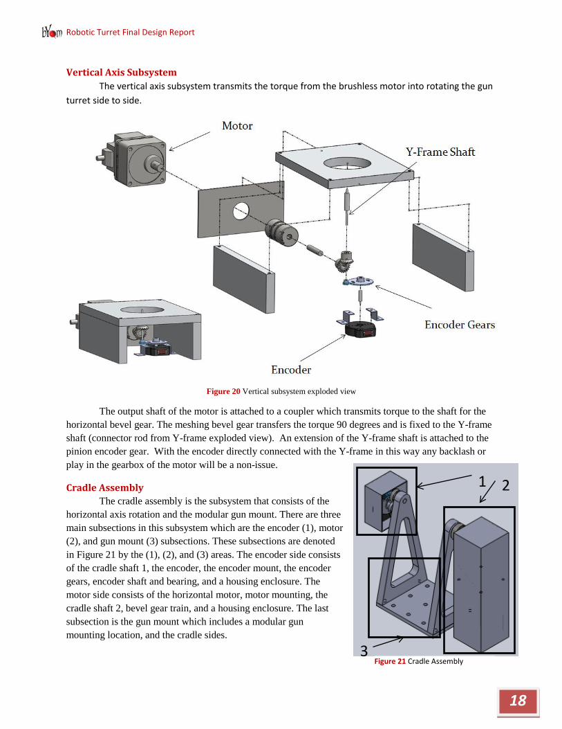
Vertical Axis Subsystem The vertical axis subsystem transmits the torque from the brushless motor into rotating the gun turret side to side.
Figure 20 Vertical subsystem exploded view
The output shaft of the motor is attached to a coupler which transmits torque to the shaft for the horizontal bevel gear. The meshing bevel gear transfers the torque 90 degrees and is fixed to the Y-frame shaft (connector rod from Y-frame exploded view). An extension of the Y-frame shaft is attached to the pinion encoder gear. With the encoder directly connected with the Y-frame in this way any backlash or play in the gearbox of the motor will be a non-issue.
Cradle Assembly The cradle assembly is the subsystem that consists of the
horizontal axis rotation and the modular gun mount. There are three main subsections in this subsystem which are the encoder (1), motor (2), and gun mount (3) subsections. These subsections are denoted in Figure 21 by the (1), (2), and (3) areas. The encoder side consists of the cradle shaft 1, the encoder, the encoder mount, the encoder gears, encoder shaft and bearing, and a housing enclosure. The motor side consists of the horizontal motor, motor mounting, the cradle shaft 2, bevel gear train, and a housing enclosure. The last subsection is the gun mount which includes a modular gun mounting location, and the cradle sides.
2
3
1
Figure 21 Cradle Assembly

Robotic Turret Final Design Report
19
Figure 22 Encoder Assembly Figure 23 Motor Assembly Figure 24 Gun Mount Assembly
W Rbz
Raz
Rax Rbx
Tv
Figure 26 Freebody Diagram Top view
Figure 25 Free body diagram front view

Robotic Turret Final Design Report
20
Analysis:
The entire system was initially modeled as a whole to find the reaction forces (Ra and Rb) due to weight (W), firing forces (Fs), and gear forces (Fg). The free body diagrams in 2 planes can be seen in Figures 25 and 26. The total reaction forces for the bearing locations A and B were found to be 22.5lbs and 61.8lbs respectively. These forces arise from a 40lb force from firing (Fs), an 80lb force from the gear train (Fg), and the torque (Tv) that could be input while the turret is turning on its vertical axis. Shear and moment diagrams where then generated for the entire system to be used in further analysis (See appendices). This analysis was done with all these forces acting at the same time which would not be the typical case adding in another factor of safety. Once all these overall reactions were found we could then track the forces through each component. The overall size of the cradle was determined from the size of the gun being used. The bovine medicinal dart gun had a height of 7in. from the bottom to the barrel and an assumed width of around 2in. This required a cradle that was at least 2in. wide and 7in tall.
Encoder Side:
As seen in figure 27 there are multiple shafts and parts that must be fastened together. Cradle shaft 1 (1) in figure 28 will be pressed into the hanger side (2) then cradle shaft 1 (1) will be pressed into the bearing (3). The bearing is pressed into the side of the Y-frame. The pinion (4) will then be pressed onto cradle shaft 1 (1) as shown. The gear (5) and encoder (6) will have their own shaft (7). The gear (5) is pressed onto the shaft (7) and the encoder (6) is held to the shaft (7) by set screws. Another bearing (8) is used in the Y-frame to hold the whole system rigidly. The last part of this assembly is the enclosure (9) which will be attached to the y-frame and functions to house all the components from getting damaged and from hurting people in terms of the gears.
Stress Analysis and Sizing:
The first design goal and parameter for the encoder side was to size the cradle shaft 1, labeled 1 in Figure 28, to take the moment applied by the cradle. In order to keep the shafts as small as possible we are going to use 4130 chromoly steel with an ultimate tensile strength of 106Kpsi. On the
1 2 3
4
5 8
7
6
9
B A C
Figure 27 Encoder Assembly exploded view
Figure 28 shaft critical stress locations

Robotic Turret Final Design Report
21
small shaft there were 3 critical areas labeled areas A, B, and C in figure 29 Area A is critical because it has the maximum moment of anywhere in the shaft which is 16.85lb-in. The size of this area needs to be at least 0.22in. to not yield under fatigue loading with a factor of safety of 2. Points 2 and 3 are critical because there is a stress concentration due to the step up in shaft size right there. These points proved to be less critical than point 1 because of their lower moments. This resulted in the shaft needing to be 0.25in. In order to use more common bearings that shaft was actually stepped up to 0.3125in. From this a bearing was picked to fit the shaft size and reaction forces. The shaft size was the limiting factor for the bearing size not the reaction stresses.
The last part of the shaft is where the encoder gears attach. This part of the shaft was sized only to fit in the gear since there will very little stress from the encoder.
The next part that was picked for the encoder side subsection was the encoder itself. In order to meet our design requirement for accuracy of (5in. @ 100ft.) we decided to go with a 10000 count encoder reduced down by a factor of 3. This means there are actually 30000 location counts for the horizontal shaft. This will allow for very accurate position measure and control. An anti-backlash gear was used for this reduction in order to keep positioning accurate.
The encoder shaft was sized to fit in the gear and not with any stress analysis since the encoder and gear will not cause any amount of worrisome stresses. The bearing for this shaft was sized only to fit on the shaft.
Gun Mount:
The sides of the gun mount will be pressed onto the main cradle shafts 1 and 2. The bottom plate will be simply bolted onto the sides seen in Figure 31 as locations 1. Then the bottom plate will have a pattern of holes that will allow for many different gun mounting configurations (location 2).
Cradle Sides:
In order to find the forces that would be in the gun mount members we first started by analyzing the interface between the side mount and the cradle shaft 1. The side would have to completely react the bearing force that is applied at point A (Ra). This means that the reaction at the bolts would be 11.1lbs in the x-direction and it was assumed that the bolts equally share the load. The torque from the motor (Tm) would also need to be reacted through
1
2
1
1
1
Ra
Tm Z
X
Y
Axis
Figure 29 Cradle bolting and mounting locations
Figure 30 Bending and shear free body diagram

Robotic Turret Final Design Report
22
the cradle side. The torque produced by the motor and the x-direction reaction forces created unequal z-direction forces on the two bolts of 39.4lbs and 43.0lbs. The z-direction forces produce only an axial stress which can be ignored. The x-direction forces together produce a moment about the rotation axis. A bending stress analysis was done using these forces and holding the rotation axis fixed. For a ¼in. think piece of 6061 aluminum this only created 1100psi of stress which is well below the yield of the material at 40000psi. With the stress being so low a fatigue analysis was not required. The sides were then sized up to .5in. thick in order to accommodate the ¼in. mounting bolts. This allowed for much of the inner material to be stripped away without reducing the safety.
Bottom:
Using the bolt forces from the side analysis and the gun shooting force the reaction forces at the other side of the bottom were found. The main mode of stress in the bottom plate is a torque put on it by the gun firing force. Using torsion equations for a square beam the maximum stress in the bottom plate was found to be 388 psi for a .25in. thick plate. This is also well below the yield stress of 40000psi for the 6061 aluminum.
Motor Side:
The motor side is put together very similarly to the encoder side of the cradle which can be seen in Figure 32. The cradle side (1) will be pressed onto the cradle shaft 2 (2). The cradle shaft 2 (2) will then be pressed into the bearing (3) that is pressed into the Y-frame. A bevel gear (4) will then be pressed onto the end of the shaft (2) to change the turning direction to the motor orientation. The other bevel gear (5) will be pressed onto a shaft (6). The shaft is attached to a coupler (7) which is then attached to the motor output shaft (8). The motor has its own sheet metal mounting bracket (9) that will attach it to the y-frame. All of these components will be covered by a sheet metal housing (10).
1 2 3
4
5 6
7
8
9
1
Figure 31 Motor assembly exploded view

Robotic Turret Final Design Report
23
Stress Analysis and Sizing:
As with the encoder side the first thing to be analyzed and sized was the main support shaft cradle shaft 2. This main support shaft is much different than the other side because it has to
be able to take the motor torque, bending stresses, and gear stresses all at once. The shaft was modeled as being simply supported and having a reaction torque in it to counteract the torque of the motor. This caused the shaft to be considerably larger than the other side’s shaft. This shaft had six critical areas that needed to be analyzed. All points were analyzed with for fatigue and with a factor of safety of 2 for 4130 chromoly steel. The first point is the gun mount side attachment where there is a high moment. The diameter of point 1 needed to be 0.41in. The next critical point, point 2, is critical because there is still a moment in the shaft at the bearing because of there is a force coming from the gear at the end of the shaft. It was found that this point needs to be 0.39in. in order to not yield the material. The next two critical points, points 3 and 4, are critical because of the stress concentration due to a step up in the shaft. Both points need to be 0.49in. in order to not yield. Critical point 5 is at the centerline of the gear. This point does not have any bending moment but it still has all the torque from the motor so it will still need to be sized. Using these criteria point 5 needs to be 0.25in. in diameter. There is one more critical point on this shaft and that is point 6 where the shaft steps down for the gear. This step down is needed so that the gear can be fitted onto the shaft. This point was found to need to be .355in. This yielded a final shaft that has a large diameter of .5in. and a small diameter of .375 in.
The bearing for this shaft was once again picked due to the shaft size not because of the reaction forces that the bearing would need to take.
Bronze bevel gears were sized from manufacturer 1 that would hold up to the motor torque of 2lb-ft. Bevel gears are used here so that the motor can be oriented vertically instead of sticking very far out horizontally. The second bevel gear is mounted to a shaft that fits the gear and then to a coupler to attach to the motor.
The motor will be held on by a sheet metal mounting bracket that will attach directly to the y-frame. The mount was modeled as simple cantilevered beam that attached to the four mounting holes of the motor. Doing a simple bending calculation it was found that the plate attaching the motor only need to be 0.0182in. thick to withstand the torque applied by the motor. The mount was then designed using .08in. thick material to give it better stiffness. The mount is also designed as an L so to give a good bolting surface to mount to the Y-frame.
1 3
2
5 4 6
Figure 32 Shaft critical stress locations

Robotic Turret Final Design Report
24
The last part of the motor side of the cradle is the simple sheet metal housing. The housing will clip on and be used to enclose everything from being damaged and to keep the dangerous gears covered up.
Motor Selection Two large motors are needed for the operation of the gun turret itself, one motor to turn the gun
turret about its vertical axis and one to turn it about its horizontal axis.
Vertical Axis
For the vertical axis we decided to go with a brushless DC motor. The brushless DC motor was chosen for its high torque to size capabilities and will give unlimited positioning capabilities. Our design specifications for this motor are that it needs to turn the turret 90 degrees in 0.5 seconds. To achieve this a triangular velocity profile was used as seen in Figure 34. This gives the turret a maximum speed of 6.28rad/s or 60rpm. From a simple Solidworks model the moment of inertia was
found and used to find the maximum torque needed to accelerate the turret sufficiently. Using work-energy and the maximum velocity the torque needed was directly calculated to be 5.5lb-ft. From these two parameters we were then able to pick a motor that would do the job. From oriental motors we picked the BLH450KC-50 brushless DC motor to fit these specifications (see data sheet in Appendix). This motor has a built in gearbox so that the high rotational speed of the motor can be geared down and more torque is available.
Horizontal Axis
For the horizontal axis we decided to go with a DC stepper motor because of the torque holding capabilities. The stepper will be able to hold the gun in place horizontally when the CG is not aligned directly with the rotational axis. The design specifications for this axis of rotation are it needs to move 30 degrees in 0.5 seconds. Again using a triangular velocity profile the maximum speed of rotation needed to be 2.09rad/s or 20rpm. Similar to the Vertical axis a Solidworks model was used to estimate the moment of inertia for the horizontal axis. Using work-energy and the maximum velocity a torque of 2 lb-ft was found. The PK564AWR27LT10 geared stepper motor was picked from oriental motors to satisfy the required specifications (see data sheet in
Appendix). This stepper motor has a basic step angle of .072deg which corresponds to an accuracy of 1.5in. at 100ft. This accuracy can be
01234567
0 0.2 0.4 0.6
Velo
city
(rad
/s)
Time (sec)
Figure 33 Motor acceleration plot
Figure 34 Horizontal Motor

Robotic Turret Final Design Report
25
increased when the stepper is controlled to go half or quarter steps. This motor also has a built in gearbox in order to achieve the torque and speed requirements.
Camera Turret The camera turret is similar to the gun turret in its conceptual design. However, there are some
key differences. The first is that it is top mounted instead of center mounted. For the gun turret, a center mount was chosen to minimize the reaction forces and to make the torque needed by the side motor only as much as was needed to overcome the inertia of the gun. This is not necessary for the camera turret, because the loads placed on its cradle will be much smaller. The motors that fall into this range will only cost about ten dollars, and slight increases in torque are hardly noticeable in the price. Since top mounting is more modular with its ability to mount to just about anything and it’s easier to design, the top mounting method was chosen for the camera turret.
The other major difference is in the motor choice. The range for the camera turret only needs to be about thirty degrees for the vertical axis, and about twenty degrees for the horizontal axis. The horizontal axis is smaller due to the fact that the gun turret will already handle most of the vertical axis rotation. Doing these ranges in a half second leads to much smaller torque and speed requirements than the gun turret, which makes much larger motions. This allowed us to pick very cheap motors with plastic gearboxes. The other point to note about the motors is that the horizontal axis here is a DC motor instead of the stepper motor like the gun turret. A stepper motor was chosen for the gun turret because it needed a larger holding torque to support the gun, and DC motors have virtually no holding torque. However, there is a gain in the holding torque from the inertia and friction of the gearbox. While this gain from the gearbox was not enough for the gun turret, it was more than enough for the camera horizontal axis.
Figure 35 Camera Turret
As stated before, the camera turret is very similar to the gun turret but in some areas where there were couplers on the gun turret, there are now fitted custom shaft connections instead. This is because the couplers were generally too large for the purpose of the camera turret, and custom fittings for the D and double flat shaft of the motor would transmit plenty of torque without breaking or slipping. From the

Robotic Turret Final Design Report
26
stress analysis calculations the smallest available parts for the camera turret components were determined to be more than capable of handling the small loads from the weight and mass moment of inertia of the camera and laser diode.
Figure 36 Camera turret exploded view
The camera turret consists of three main subsystems, the rotating platform, the cradle, and the camera-laser mount. Two identical DC motors are used to drive the two axes. The vertical axis is mounted to a shaft with a double flat shaft hole to fit on the motor. This shaft is press fit into a bearing which is press fit into the bottom plate. This same shaft then goes up to the rotating stage and is press fit into it. That encompasses all of the rotating platform subsystem.
The cradle subsystem is connected to the rotating stage by two arms with press-fit bearings. These are then press-fit onto a shaft that is press-fit into the cradle. Calculations will be done to verify that the press fit can take the torque without slipping. This same shaft is connected onto a machined coupler shaft. This coupler will have the double flat hole to connect onto the motor on one side, and a regular press fit hole to connect onto the shaft on the other side.
Finally, the camera-laser mount subsystem is mounted onto the cradle with bolts. This mount is just a solid piece of material for the camera and laser to mount onto. Right now, there is a design for it that will be similar to the final design, but we will make the final design once we have the camera and laser to see how they are meant to be mounted to. Right now we are unsure because there is not enough information online about these items. These are the basics of the camera turret.

Robotic Turret Final Design Report
27
Electronics Most of the electronics design for the robotic turret has entailed picking out the necessary prebuilt
components. The following table gives a list of the electronic components and what they will be used for. There is a diagram in the appendices that show the general connections of all the electronic parts.
Table 6 Explanation of electronic parts
Electronic Component Use Cost
Camera Handles the target recognition, as well as searches for the laser point to calculate distance $40.00
Jetway Computer Handles all of the vision processing, higher level algorithms, and communication to the GUI $250.00
Arm 7 Microcontroller Performs all sensor data handling, PID motor control, and power control to the sensors $30.00
Jtag Transfers compiled C++ code from the computer onto the microcontroller $71.95
Laser Module Pulses on and off when controlled, so the pixels on the image and the pixels away from the image center can
be counted for distance measuring. $33.24
Dual Camera Motor Driver
Allows for the higher voltage and current needed by the camera motors that the microcontroller can't handle $8.45
Stepper Driver Allows for the higher current needed by the stepper motor that the microcontroller can't handle $19.95
DC Driver Allows for the higher voltage and current needed by the vertical axis DC motor that the microcontroller
can't handle $34.95
There will be some board design to handle the power management for the different devices from our battery, as well as choosing the right battery. This has been put off for now so we can perform tests on our electronic components, to see how much current everything draws when running together. That will allow us to adequately size our battery, and then there is the task of making a few simple circuits to handle current protection and to convert voltages. Until this testing is done, we will use a power supply to handle the testing and coding.

Robotic Turret Final Design Report
28
Programming The programming will be mostly worked on during the summer. The flow of tasks that need to be done is as follows:
• Device drivers will be written for each component • Function classes will be written for each component • Packet nomenclature will be written for the serial communication between the microcontroller
and computer • A kinematics algorithm and Angle conversion will be written to take distance and give position
for the turret • Data handling classes will be written for both the computer and microcontroller to decide what
tasks are performed and when they run. • Object recognition and tracking for the camera will be written • Distance sensing calculations will be written • A PID controller will be created for each motor specifically • A Graphical User Interface (GUI) will be created for easy use of the turret by an average person
There are task-state diagrams that demonstrate visually the flow of code in the appendices. There are a few task-state diagrams included in the appendices, but they are not all there because they are really similar. The analysis for the kinematics, distance sensing, and angle conversion have not been performed yet. However, once they are done, they can be entered only once in a way that will handle of the situations.
The most complicated aspect of the programming will be the vision software. Most of the testing and programming this summer will be dedicated to getting accurate circle and laser recognition from the camera, and using that data to give accurate distance calculations for the target. If this can be done well, the rest of the code will be much simpler, as PID control, kinematics, and angle conversions have been done numerous times, and there is plenty of literature and example code to be found. The overall code architecture is shown in a diagram in the appendices.
4.3 System Dynamics Analysis To completely understand how the system would work, a system analysis was done which
consists of dynamic analysis of the projectile from the gun to the target. Preliminary projectile motion was done in both Cartesian and cylindrical coordinates and is ready to start being coded into the computer.
In order for the turret to know exactly where to point the gun in order to hit the target it has identified projectile motion equations will need to programmed into the computer. The sensors will provide the location of the target relative to the turret and from that the computer will decide how to aim the gun in order to hit the target. To do this projectile motion analysis is done to find out how the projectile will actually move and act. Target position and initial velocity will be input into these equations and the trajectory of the projectile will be selected. Using the two degrees of freedom on the turret the turret will be positioned to satisfy the needed trajectory. Using basic dynamics the projectile motion can be determined.

Robotic Turret Final Design Report
29
The first attempt to model the projectile motion was done in Cartesian coordinates. These coordinates are easy to use and we were able to get the motion of the projectile easily. The Cartesian analysis was done in 3-D and took into account the drag that will be on the projectile. But these equations are not that useful when using a sensor system on a turret. The turret will output the range and angle of the target relative to the turret. This means it would be more useful for our projectile motion equations to also be in cylindrical coordinates. Although cylindrical coordinates are harder to use than Cartesian but are more applicable to the situation. A first run of the projectile motion equations in cylindrical coordinates has been completed. Going to cylindrical coordinates is another stepping stone on the process to using spherical coordinates in the same way using Cartesian coordinates was. Spherical coordinates uses two angles and a radial distance to determine position in a three dimensional space. Since the sensors will output two angles and a radial distance when the target is moving up and down, spherical coordinates will be the most applicable and our coordinate system of choice.
4.4 Cost Analysis We priced all of the purchasable parts from vendors on the internet and reached a grand total of $3,686.
Table 7 Estimated Costs by Subsystem
System Item Quantity Unit Cost Total Cost System Cost Yframe Y frame tube 1 $20.00 $20.00 $874.07 Raw Aluminum 1 $50.00 $50.00 Stainless steel tube 1 $5.00 $5.00 .69" thick al plate 1 $92.00 $92.00 .1" sheet metal 1 $12.00 $12.00 .5" al plate 1 $19.00 $19.00 .5" al plate big 1 $61.39 $61.39 Horizontal Housing Sheet 1 $16.58 $16.58 antibacklash 90 teeth 1 $64.98 $64.98 encoders 1 $73.12 $73.12 DC Motor 1 $460.00 $460.00 Cradle Cradle Sides 1 $26.28 $26.28 $632.08 Cradle Bottom 1 $16.38 $16.38 Cradle Shaft material 1 $15.64 $15.64 Horizontal Shaft Coupler 1 $22.55 $22.55 Horizontal Encoder Bearing 1 $1.70 $1.70 Horizontal Shaft housings 1 $47.93 $47.93 Horizontal Large Bearing 1 $10.64 $10.64 Horizontal Small Bearing 1 $10.74 $10.74 antibacklash 120 teeth 1 $69.10 $69.10 Stepper Motor 1 $338.00 $338.00 encoders 1 $73.12 $73.12 Camera Turret Camera Turret Components 1 $60.00 $60.00 $390.20 Camera Turret Aluminum 1 $40.00 $40.00

Robotic Turret Final Design Report
30
encoders 2 $73.12 $146.24 Camera Motors 2 $7.00 $14.00 antibacklash 90 teeth 2 $64.98 $129.96 Electronics etc. Camera 1 $40.00 $40.00 $520.89 Jetway Computer 1 $250.00 $250.00 Arm 7 Microcontroller 2 $30.00 $60.00 Jtag 1 $71.95 $71.95 Jtag cord 1 $2.35 $2.35 Laser Module 1 $33.24 $33.24 Dual Camera Motor Driver 1 $8.45 $8.45 Stepper Driver 1 $19.95 $19.95 DC Driver 1 $34.95 $34.95 Overall Components Bolts (box of 50 large) 1 $20.00 $20.00 $318.77 Bolts (box of 50 small) 1 $12.00 $12.00 Nuts (box of 50 large) 1 $7.00 $7.00 Nuts (box of 50 small) 1 $5.00 $5.00 Washers (box of 50 large) 1 $7.00 $7.00 Washers (box of 50 small) 1 $5.00 $5.00 Tools etc 1 $200 $200 10ft unstretched wire (4 con) 1 $33.35 $33.35 10ft unstretched wire (2 con) 1 $29.42 $29.42 Miscellaneous Paintball gun 1 $150 $150 $950 extra material 1 $200 $200 Battery 1 $100 $100 Shipping 1 $500 $500 Extra (Maybe) power supply 1 $50 -$300 $50 -$300
Grand Total
$3,686.01

Robotic Turret Final Design Report
31
Chapter 5: Project Timing Our action plan boils down to the manufacturing Pert Chart and the Design Verification Plan and Report. These plans will be utilized through the execution of our Project Management Plan.
Table 8 Overview of schedule for official senior project months
5.1 Manufacturing Plan Scott Mullens will be in charge of our manufacturing. The plan of how to manufacture all the components in a timely manner is described below in the Pert Chart of Figure37 The manufacturing will be completed in the Cal Poly machine shops, Mustang 61 and the hangar.
Figure 37 Pert Chart

Robotic Turret Final Design Report
32
5.2 Overall Project Timing To complete the rest of this system design, build, and test process, we have broken up the rest of the
project into four categories. These categories are listed below along with who is heading them and some of the tasks that will go into them. The Gantt chart in the appendix goes into more detail into the tasks and timeline.
Table 9 Management Plan Breakdown
Subsystem Physical Electrical Software Manufacturing
Leader Rachel Matthew Daniel Scott
Responsibilities: Including but not
limited to.
Turret Structure Power Management Device Drivers Ordering components
Turret Aesthetics Wiring Software Architecture Machining
Component Placement Communication Aiming Algorithm Assembly
Each person heading their section will come up with the specific tasks and the order in which these tasks will be executed. The category lead will delegate each task to the most apt person, so that our time will spent efficiently with someone checking the big picture in each section.
5.3 General Testing Scheme We plan to test each part individually as they arrive and then test each component relationship as
quickly as possible. Then each subsystem will be tested followed by the robotic turret as a whole.
Table 10 Individual part, relation, and overall function for various subsystems
We began devising tests to include in a Design Verification Plan & Report (DVP&R). They are subject to change but will act as a springboard to expand from when we proceed the testing phase. Table 6
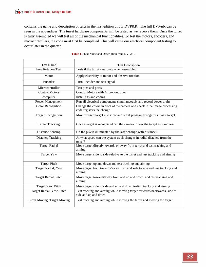
Robotic Turret Final Design Report
33
contains the name and description of tests in the first edition of our DVP&R. The full DVP&R can be seen in the appendices. The turret hardware components will be tested as we receive them. Once the turret is fully assembled we will test all of the mechanical functionalities. To test the motors, encoders, and microcontrollers, the code must first be completed. This will cause our electrical component testing to occur later in the quarter.
Table 11 Test Name and Description from DVP&R
Test Name
Test Description
Free Rotation Test Tests if the turret can rotate when assembled
Motor Apply electricity to motor and observe rotation
Encoder Turn Encoder and test signal
Microcontroller Test pins and ports Control Motors Control Motors with Microcontroller
computer Install OS and coding Power Management Run all electrical components simultaneously and record power drain Color Recognition Change the colors in front of the camera and check if the image processing
code registers the change Target Recognition Move desired target into view and see if program recognizes it as a target
Target Tracking Once a target is recognized can the camera follow the target as it moves?
Distance Sensing Do the pixels illuminated by the laser change with distance?
Distance Tracking At what speed can the system track changes in radial distance from the turret?
Target Radial Move target directly towards or away from turret and test tracking and aiming
Target Yaw Move target side to side relative to the turret and test tracking and aiming
Target Pitch Move target up and down and test tracking and aiming Target Radial, Yaw Move target both towards/away from and side to side and test tracking and
aiming Target Radial, Pitch Move target towards/away from and up and down and test tracking and
aiming Target Yaw, Pitch Move target side to side and up and down testing tracking and aiming
Target Radial, Yaw, Pitch Test tracking and aiming while moving target forwards/backwards, side to side and up and down
Turret Moving, Target Moving Test tracking and aiming while moving the turret and moving the target.

Robotic Turret Final Design Report
34
Chapter 6: Product Realization
6.1 Manufacturing Process
Cradle
Figure 38 Exploded view of cradle assembly
The first parts of the cradle that were made were the stepped shafts for the horizontal axis rotation in Figure 38. These stepped shafts were made on the CNC lathe in the Hanger on the Cal Poly Campus. They were able to be made with simple turning and facing operations. The outside diameters were monitored diligently in order to insure a good press fit with the rest of the parts.
The next parts that were made were the cradle sides along with cradle bottom. The bottom was a fairly simple part that required the shape to be cut on the band saw and mounting holes to be drills. The mounting holes were drilled using a mill for location accuracy.
The first thing to do on the cradle sides was to drill the mounting holes in the bottom. This was done before the stock had been cut up at all. The second thing was to cut out the sides on a CNC mill in order to accomplish the curved geometry and to very accurately make the holes for the press fits.
A small shaft was made to couple with the motor and has a press fit for the gear. There are also motor mounts for the horizontal motor that were made on a manual mill and are different than what is shown in Figure 39. One of the gears was also drilled out to fit on the shaft and press fit.

Robotic Turret Final Design Report
35
Y-Frame
Figure 39 Exploded view of Y-frame.
The first thing manufactured on the Y-frame were the two upright sides. As with the cradle sides the mounting holes in the bottom of the Y-frame were the first thing to be done. These holes were located and drilled in the stock on the mill for accuracy before anything was cut out. The next step was to cut these out on a CNC mill. A CNC mill was used in order to accomplish the curved nature of the part and to also insure that the bearing surfaces were accurate. The mounting holes for the motor mount and gear mounts were also done in this CNC step to insure their relative location to the horizontal axis is accurate.
The second part manufactured for the Y-frame was the bottom plate. The plate was cut out and drilled also using a CNC mill. A circular notch was placed in the bottom of the plate for the post to sit in for locating purposes.
The post and bottom cap were made on a CNC lathe. The post was a simple part that was cut close to length on a band saw and then faced down on the lathe for length accuracy and for squareness.

Robotic Turret Final Design Report
36
The bottom cap was turned and faced to size on the lathe and the hole in the center of it drilled. After the hole was drilled the cap needed to be broached for a keyway. Using a broaching kit and a press making the key slot was simple.
The bottom cap interfaces with a shaft through the key way. This shaft was machined on a CNC lathe and made for a slip fit in the lower bearing, a press fit on the gear, and a slip fit to the bottom cap. The shaft was also has a key way in it made on a manual mill.
Base Structure
Figure 40 Exploded view of base assembly
The first part to be made in the lower assembly was the table bearing plate at the bottom of figure 40. This plate was made on a CNC mill in order to achieve accuracy in the bearing surface and also for the mounting hole locations.
The next parts to be made were the side plates, shown in Figure 40, for the bevel gear housing. The plate with the bearing hole was made on a CNC mill also for bearing accuracy. The mounting holes were located and drilled on a manual mill. The lower plate was also made on a CNC mill for bearing accuracy. The mounting holes were also drilled at this time.
The gear on the vertical axis was then drilled out to be press fit onto the shaft.

Robotic Turret Final Design Report
37
Four legs to elevate the entire lower assembly off of the mounting plate were also made using a manual mill. The legs are not shown in the exploded view shown above for simplicity. An encoder spacer was also made on a manual mill and is not shown in Figure 40. This spacer consisted of small aluminum block with two through holes for mounting purposes.
Two shafts were also needed for the lower assembly. The first, being the motor connection shaft. This shaft was turned and faced to length on a CNC lathe. Then, a key slot was cut into it using a manual mill. The key slot was necessary to transfer torque through the coupler to the motor.
The vertical motor mount was made using a simple flat plate of aluminum. This plate was milled out to fit the shaft through and has mounting holes for the motor and for mounting it to the bottom mounting plate. The bottom mounting plate was made using a drill press, and the hole pattern from the CAD model. The bottom plate offered a heavy stable mounting point.
Assembly
Cradle and Y-frame
The assembly of the whole system started with the Cradle and the Y-frame. First, the upper shafts were pressed into the cradle sides. Next, the bearings were pressed into the Y-frame sides. Finally, the upper shafts were pressed into the bearings. On the motor side the gear was then pressed onto the end of the shaft.
The Y-frame bottom next needed to be welded for the assembly process to continue. The post was welded on to the bottom using the circular notch in the bottom to locate it. The post was also welded at the other end to the bottom cap.
When both sides of the Cradle and Y-frame were all pressed together, the cradle bottom and the Y-frame bottom were bolted on. At this point, the motor horizontal motor could also be mounted to the side of the Y-frame. Using the motor mounts and the shaft mount, the motor, shaft, shaft coupling, and gear were all bolted up and aligned. Washers were used in order to locate the motor and shaft to achieve proper gear meshing.
Bottom Assembly
The bearings were pressed into their respective locations. All of the rest of the parts were simply bolted together. The encoder was set-up per the instructions on the manufacturer’s website. The entire assembly was stepped off of the bottom plate with washers because of a greater unforeseen thickness from the encoder. The horizontal gear is pressed onto its shaft. The coupler to the motor is simply slip fit onto the shafts, and the set screws are tightened down. There is sufficient play in regards to the coupler location to allow for axial adjustment of the gears.
Electrical System There were two systems when it came to the coding for the turret. The first is the position
sensing computer and the other is the motor controller. The position sensing involves tracking a circle with a camera, converting the position to an angle to, and then transmitting that data across the USART. The code to track circles has been written many times, and there was a lot of example code to use online.

Robotic Turret Final Design Report
38
We chose to go with OpenCV's vision libraries, for they are used a lot in robotics and are open-source. After looking at the similar projects shown online for tracking circles, the technique was found to be the same in each one. So, we used the same approach and altered it slightly for our needs. The technique begins looking for a certain color and giving it a range of brightness and saturation for leniency. Then, you make a black and white image where the white represents anywhere that the desired color was in the picture. Once you are in only black and white, a simple, circle blob detection is done, which works well in with black and white. In the end, we had a system that could follow a circle at about 30fps in any color we chose. The angle calculations took the data from the circle tracking (an x-y position of the circle on the picture) and converted it to an angle based on the difference in view points of the gun and the camera. Because this code would only ever occur if a circle was found, it was included in the same loop as the camera code.
In order for the robot to work in real time, we needed to have the circle tracking code working at a constant 30Hz and still be able to send data over the USART at the same time. On the computer this is concept is already handled by the operating system. Using a system called multi-threading, you can basically create a different thread for every process you want occurring simultaneously, and the internal scheduler decides when to run different pieces of the code to make it appear simultaneous. We had a thread for the camera to angle code, and then another for sending data.
On the micro-controller this is a little more complicated. The speed of the micro-controller is not enough to handle that kind of scheduling. Therefore we used a concept known as cooperative multitasking. You can still have multiple processes appearing to run simultaneously, but you have to split these tasks up more intelligently into different states of the task. This involves drawing a task-state diagram which shows how many different states are in your task and what factors lead into changing into another state. From there, the concept is simple. With every single pass through the control loop, the program will perform one state from each task, and as you progress through the states, the task is being completed. Since this happens at such a high rate compared to what we can see, it looks like it is all happening at the same time.
Once we had our task-state diagrams created, it just had to be translated into C++. Since motor control is very common in code and we had already written some for another class, the micro-controller code was simple. As the data came in from the computer, it was stored to a buffer to be read into the motors when needed. There were only two tasks here as well. One task read the data into the correct places, and the other task ran the PID control for the two motors. The encoders were run on interrupt basis so as to not miss any ticks. This is not exactly cooperative multitasking since it will block the rest of the program whenever a tick is found, but as long as the code is small when interrupted, it isn't noticeable. With all of these pieces, you have our entire system. The flow is as follows:
The camera finds a circle and then translates it to angles for the motors to go to. The angles are transferred across the USART. The micro-controller receives it and save it to the correct variables. The PID controller reads the variables and is controlled to that location.
To create an aiming algorithm from the camera to the turret, the view of the camera had to be scaled to real world dimensions. This was accomplished by setting the camera up in known position facing a white wall. While the camera displayed its view on a computer screen, a rectangle was drawn on

Robotic Turret Final Design Report
39
the wall which represented the outline of the camera’s view. The rectangle outline and the distance of the wall to the camera were both measured. With this information, we were able to scale the camera’s view to the real world dimensions at the specified distance. With the real world dimensions of where the object was relative to the camera, we could calculate gun’s real world position as well. With this method, we were also able to find the camera’s degrees of viewing range.
To design the electrical system, the documents of the Atmega128 board, controller, motor driver
and encoder were analyzed to determine appropriate wiring. During the testing of the system and all of its components, the wiring was done by loosely soldering and taping leads together for temporary attachments. Since the Atmega128 board did not fit into our bread board, wires were soldered onto the pins in use and then plugged into the bread board, which can be seen below in Figure 41. After testing, permanent wiring was done with soldering all necessary wires and pins, eliminating all extra unused wires, and twisting and wrapping wires in electrical tape. This was done to eliminate noise and clean up the appearance and ease of use of the system.
Figure 41 Microcontroller on breadboard
6.2 Differences in Prototype from Design
The motor mounts differ completely from what was in our plan. The motor mounts need to be very strong and also very accurate. With the teams abilities in mind, it was determined that the motor mounts could not be made effectively out of sheet metal. The mounts were changed to a milled part that could be easily made on a manual mill and would ensure mounting accuracy. The press fit on the gear mounted horizontally failed requiring the addition of a set screw. The set screw worked, but in the end, elongated the hole in the brass gear causing high amounts of slope for that axis. The encoder for this axis was also left off, because the backlash gear that went to this encoder had the wrong bore, meaning it would not go on the shaft.
The hole in the bottom cap and the corresponding shaft size were enlarged when compared to our original plan, because the smaller broach size was not available. The bottom cap had a machining error on the bearing interface. Due to this inaccuracy, shim stock was placed there to take out the slope. The press

Robotic Turret Final Design Report
40
fit for the vertically oriented gear also failed here. In order to still transfer torque, the gear was also broached and the key slot lengthened on the shaft.
The vertical motor mount was also changed to a simple flat plate for accuracy and ease of manufacturing. Making an accurate sheet metal mount was out of our skill set. The lower shaft and coupler were also a change from the original design. The original design called for a coupler to be made, but this was deemed unmanufacturable, and so the current design was used. A shaft collar was also added over the encoder in order to take any axial loading from the bevel gear. The vertical bevel gear tries to lift off of the other gear, and the shaft collar doesn't allow this by putting that force into the bearing.
Due to time constraints, there was no implementation of the laser with the camera system. Without being able to track the distance, the distance must be known by the code before tracking an object to be able to aim the axes properly. Therefore, to accurately track an object, the desired distance must be put into the code before running the program. The object being tracked must maintain that chosen distance as well to ensure proper aim about the axes.
The prototype also differs from the final design in that the camera is not mounted on its own
turret. It was decided that the camera turret was not a vital component of the original design. When we eliminated the laser configuration, the camera no longer needed to be constantly aimed at the target. The camera instead is mounted on the base in a fixed position.
The original design included an encoder for the horizontal axis to track the stepper motor’s
position. As previously mentioned, the corresponding gear could not be used, which made us incapable of using the encoder. To rectify the problem, it was decided to track the motor’s position by counting the steps being sent to the move stepper motor. Though this method may not be as accurate as the original encoder assembly, the accuracy supplied by counting steps is the sufficient amount to aim the gun at closer distances.
Though the encoder to track the vertical axis is sufficient at tracking the motors position for our prototype, the encoder has a 90 degree range in which it is unresponsive. It is unclear whether the encoder was shipped to us in this condition or if it was damaged during the assembly of the encoder and its gear train by our group. Due to this unresponsive zone, the turret can only work within a range of around 135 degrees on either side of its center point. This damaged encoder might also explain the inaccuracy of the turret aiming over a long period of time. If the encoder is sending small amounts of false information to our microcontroller, this would cause small
inaccuracies in the turrets position relative to its desired position. However, any error within the tracking due to a faulty encoder does not affect our prototype significantly at closer distances.
When choosing our motors from Oriental Motor, it was not realized that they came supplied with their own motor driver boards. Though other motor drivers were originally chosen, it was discovered that it would be easier for coding and electrical design when using the drivers supplied by
Figure 42 Bottom Encoder

Robotic Turret Final Design Report
41
Oriental Motor. These new motor drivers increased the ease of use and appearance of the prototype, with premade connectors, wire configurations, and boards .
Figure 43 atmega-sam7s256 board and Oriental Motor driver board
The atmega-sam7s256 board that we originally ordered for the turret was not adequately
researched. Although the processor was fast at 60MHz and powered over USB (a plus for ease of wiring), there were necessities missing for the running of the turret. We have two motors and two encoders on our final design. The encoders need two interrupt pins each, and the micro-controller only has two. Also, with all of the I/O needed for the two motors and encoders, there were not enough pins available. We ordered two micro-controllers so this could be remedied by using them both, but that would require more USB ports than our computer had.
There was also an issue with documentation and library support. The sam7s processor is not commonly used, so there aren’t many examples of how to properly program the processor. A lot of work was spent trying to decipher the controller with the sparse information, and although headway was made, much of our time was wasted. For an extra $30, we could have bought a new micro-controller that we understood well, had all the pins needed. When we finally switched to it, we were able to have our system completed in two weeks, something we couldn't do in two months with the other controller.

Robotic Turret Final Design Report
42
6.3 Recommendations for Manufacturing
In the future we would change the bevel gears to a predesigned gearbox set-up. A lot of work goes into setting up the bevel gears correctly and it greatly complicates the project. Using belts for the encoders or using potentiometers for the encoders would be much easier to set up. The geared encoders must be set-up accurately while a belt would be much more forgiving.
To reduce costs, we recommend designing custom motor driver boards. Though the boards designed by Oriental Motor were helpful to reduce assembly and coding time, they were unnecessarily expensive. Designing custom motor driver boards could reduce costs by $300, though it would add extra design time. It could increase program efficiency and targeting response time. It could also decrease the amount of wiring which would decrease electrical noise and improve the appearance of the wiring. We also recommend designing a custom motor controller board. The Atmega128 breakout board was larger with more features than necessary for our prototype. The turret system can be run by a system of 14 pins, opposed to the 64 pins of the Atmega128. To decrease size and simplify the system, a different microcontroller should be chosen. The Atmega128 header board is also larger with more capabilities than necessary for the turret system. It has a pin connect for every one of the Atmega128 pins as well as to extra for powering the board. As discussed before, this amount of pins is unnecessary and only adding extra size to the system. By creating a custom board with a new, smaller controller, the size of the system could be decreased and the efficiency of the program could be optimized with the simpler setup.

Robotic Turret Final Design Report
43
Chapter 7: Design Verification
Test Descriptions The first tests performed were mechanical hardware and assembly tests. As each subassembly of the turret was completed, we tested its functionalities to verify that it operated correctly. These tests included the testing of gears, press fits, couplers, etc, and are listed below:
• Free Rotation: Does the turret rotate when assembled?
• Press Fit: Are the press fit components secure? • Coupler: Do the couplers fit snugly and
transmit power? • Gear Mesh: Do the gears mesh and transmit
torque?
The next set of tests performed was for the electrical system. Each electrical component had to be tested with code loaded on the microcontroller. The components tested are listed below:
• Microcontroller: Test pins and ports. • Motor: Apply electricity to motor and
observe rotation. • Encoder: Turn encoder and test signal. • Control Motors: Control motors with
microcontroller. • Computer: Install OS and coding.
Figure 45 Motor, Encoder, Microcontroller, Control Motors tests
Figure 44 The free Rotation, press fit, coupler and gear mesh tests.

Robotic Turret Final Design Report
44
Figure 46 Color Recognition, Target Recognition and Target Tracking tests
The target recognition tests were completed simultaneous to the target recognition coding. Once the code was written, the testing of the colors and tracking ability continuously updated the code. The tests were as follows:
• Color Recognition: Change the colors in front of the camera and check if the image processing code registers the change.
• Target Recognition: Move desired target into view and see if program recognizes it as a target. • Target Tracking: Once a target is recognized can the camera follow the target as it moves?
The final stage of testing was of the completed turret prototype. The tests were to ensure that all requirements would be met by our system. The tests are as follows:
• Target Radial: Move target directly towards or away from turret and test tracking and aiming
• Target Yaw: Move target side to side relative to the turret and test tracking and aiming
• Target Pitch: Move target up and down and test tracking and aiming
• Target Radial and Yaw: Move target both towards/away from and side to side and test tracking and aiming
• Target Radial and Pitch: Move target towards/away from and up and down and test tracking and aiming
• Target Yaw and Pitch: Move target side to side and up and down testing tracking and aiming
Figure 47 Setup for test of entire prototype.

Robotic Turret Final Design Report
45
• Target Radial, Yaw, and Pitch: Test tracking and aiming while moving target forwards/backwards, side to side and up and down
Detailed Results Successes
• Color recognition and target recognition function above expectations • Target tracking functions above expectations. • Omitting encoders, electrical system functions above expectations. • The transfer of motion from both motors to the system was achieved. • Motor and general system control from microcontroller was achieved. • Side to side aiming was achieved. • The algorithm for up and down aiming was achieved and verified.
Failures and Fixes
• One press fit gear failed and was secured by using a set screw. • The encoder on the horizontal axis motor picked up noise when the motor was being used
simultaneously. Pitch aiming failed due to the encoder malfunction. This will be rectified by counting steps through the stepper motor.
• The encoder on the vertical axis failed within a particular 90 degrees, impairing our ability to track an object over 360 degrees.
• The main bearing for the Y-Axis allows slight side to side movement. • Significant play is observable within the gearbox and coupler of the vertical axis motor.
Fortunately, the encoder sensing that axis orientation is not affected by it.

Robotic Turret Final Design Report
46
Chapter 8: Conclusion
The targeting turret prototype was concluded to be a good proof of concept. Though it did not meet all requirements originally specified, the turret operated to our satisfaction and showed that with a few fixes and improvements, our design would be a fully operating system. We were very satisfied with many of the design choices that we made. Most of our physical system design worked to our expectations and many of the electrical and computer components surpassed our expectations. The areas where our design either failed or was altered provided valuable lessons to our group in researching products, time management, and the importance of a flawless physical system. Below, we explain in detail our recommendations to fix and improve the system, and ways to cut costs.
For the system to work flawlessly, it is necessary to put an encoder on the horizontal axis. Though counting the stepper motor steps was sufficient for tracking on the prototype, an encoder with a larger accuracy is necessary for accurately tracking objects, especially at farther distances. If the original encoder that was purchased for the prototype was to be used, ordering the larger anti-backlash gear and assembling the gear train would also be necessary to optimize accuracy. To ensure accuracy of the vertical axis, the vertical axis encoder must be replaced with a working encoder. With an undamaged encoder, the turret could rotate a full 360 degrees. It would also ensure optimal accuracy of the aiming system, especially over longer periods of time.
Although the laser-camera sensing was never implemented, it is clear from our circle tracking
that this would not be effective at the 50ft range we are looking for. In the future as this project is continued, it will be better to switch to a standard laser scanner. Laser scanners, while expensive, are well tested and can give accurate distance sensing up to 30m in a 270 degree field of view. With a servo attached that pans up and down, you can get a three dimensional view of your targets and map. This saves software development time, since the laser handles most of the processing and there are many drivers already written. Laser scanners are also very common in industry, so there is a plethora of software that exists to use them in different ways, opposed to the virtually nonexistent examples for the laser-camera.
We recommend premade worm gear boxes for the 90° transition between the motor and turret
shafts instead of miter gears. The worm gears can provide an adequate gear ratio so a cheaper can be used since it won’t need its own gearbox. Worm gears can be self-locking so torques from the gun won’t transfer to the motors. Anti-backlash worm gears are available, so the encoders have more places to measure the position of the turret accurately.
We advise looking into the bending play specifications for bearings. The bearings we selected
were sufficiently strong but the bearing for the bottom of the Y-frame allowed more movement than we desired in directions other than the main rotating axis of the bearing.

Robotic Turret Final Design Report
47
Appendices
Appendix A Quality Function Deployment Chart
Appendix B Gantt Chart (Timeline)
Appendix C Cost Analysis
Appendix D DVP&R
Appendix E Task State Diagrams
Appendix F Electronics Diagram
Appendix G Programming Diagram
Appendix H Y-Frame Hand Calculations
Appendix I Cradle Hand Calculations
Appendix J Connector Rod Hand Calculations
Appendix K SolidWorks Drawings
Appendix L User Manual

Robotic Turret Final Design Report
48
Appendix A – Quality Function Deployment Chart (QFD)

Robotic Turret Final Design Report
49
Appendix B – Gantt Chart

Robotic Turret Final Design Report
50
Appendix C – Cost Analysis
System Item Quantity Unit Cost Total Cost System Cost Yframe Y frame tube 1 $20.00 $20.00 $874.07 Raw Aluminum 1 $50.00 $50.00 Stainless steel tube 1 $5.00 $5.00 .69" thick al plate 1 $92.00 $92.00 .1" sheet metal 1 $12.00 $12.00 .5" al plate 1 $19.00 $19.00 .5" al plate big 1 $61.39 $61.39 Horizontal Housing Sheet 1 $16.58 $16.58 antibacklash 90 teeth 1 $64.98 $64.98 encoders 1 $73.12 $73.12 DC Motor 1 $460.00 $460.00 Cradle Cradle Sides 1 $26.28 $26.28 $632.08 Cradle Bottom 1 $16.38 $16.38 Cradle Shaft material 1 $15.64 $15.64 Horizontal Shaft Coupler 1 $22.55 $22.55 Horizontal Encoder Bearing 1 $1.70 $1.70 Horizontal Shaft housings 1 $47.93 $47.93 Horizontal Large Bearing 1 $10.64 $10.64 Horizontal Small Bearing 1 $10.74 $10.74 antibacklash 120 teeth 1 $69.10 $69.10 Stepper Motor 1 $338.00 $338.00 encoders 1 $73.12 $73.12 Camera Turret Camera Turret Components 1 $60.00 $60.00 $390.20 Camera Turret Aluminum 1 $40.00 $40.00 encoders 2 $73.12 $146.24 Camera Motors 2 $7.00 $14.00 antibacklash 90 teeth 2 $64.98 $129.96 Electronics etc. Camera 1 $40.00 $40.00 $520.89 Jetway Computer 1 $250.00 $250.00 Arm 7 Microcontroller 2 $30.00 $60.00 Jtag 1 $71.95 $71.95 Jtag cord 1 $2.35 $2.35 Laser Module 1 $33.24 $33.24 Dual Camera Motor Driver 1 $8.45 $8.45 Stepper Driver 1 $19.95 $19.95 DC Driver 1 $34.95 $34.95 Overall Components Bolts (box of 50 large) 1 $20.00 $20.00 $318.77

Robotic Turret Final Design Report
51
Bolts (box of 50 small) 1 $12.00 $12.00 Nuts (box of 50 large) 1 $7.00 $7.00 Nuts (box of 50 small) 1 $5.00 $5.00 Washers (box of 50 large) 1 $7.00 $7.00 Washers (box of 50 small) 1 $5.00 $5.00 Tools etc 1 $200 $200 10ft unstretched wire (4 con) 1 $33.35 $33.35 10ft unstretched wire (2 con) 1 $29.42 $29.42 Miscellaneous Paintball gun 1 $150 $150 $950 extra material 1 $200 $200 Battery 1 $100 $100 Shipping 1 $500 $500 Extra (Maybe) power supply 1 $50 -$300 $50 -$300
Grand Total
$3,686.01

Robotic Turret Final Design Report
52
Appendix D – DVP&R

Robotic Turret Final Design Report
53
Appendix E – Task State Diagrams
PID Task
Switch Task
Laser Task

Robotic Turret Final Design Report
54
Appendix F – Electronics Diagram

Robotic Turret Final Design Report
55
Appendix G – Programming Diagram

Robotic Turret Final Design Report
56
Appendix H – Y-Frame Hand Calculations

Robotic Turret Final Design Report
57

Robotic Turret Final Design Report
58

Robotic Turret Final Design Report
59
Appendix I – Cradle Hand Calculations

Robotic Turret Final Design Report
60

Robotic Turret Final Design Report
61
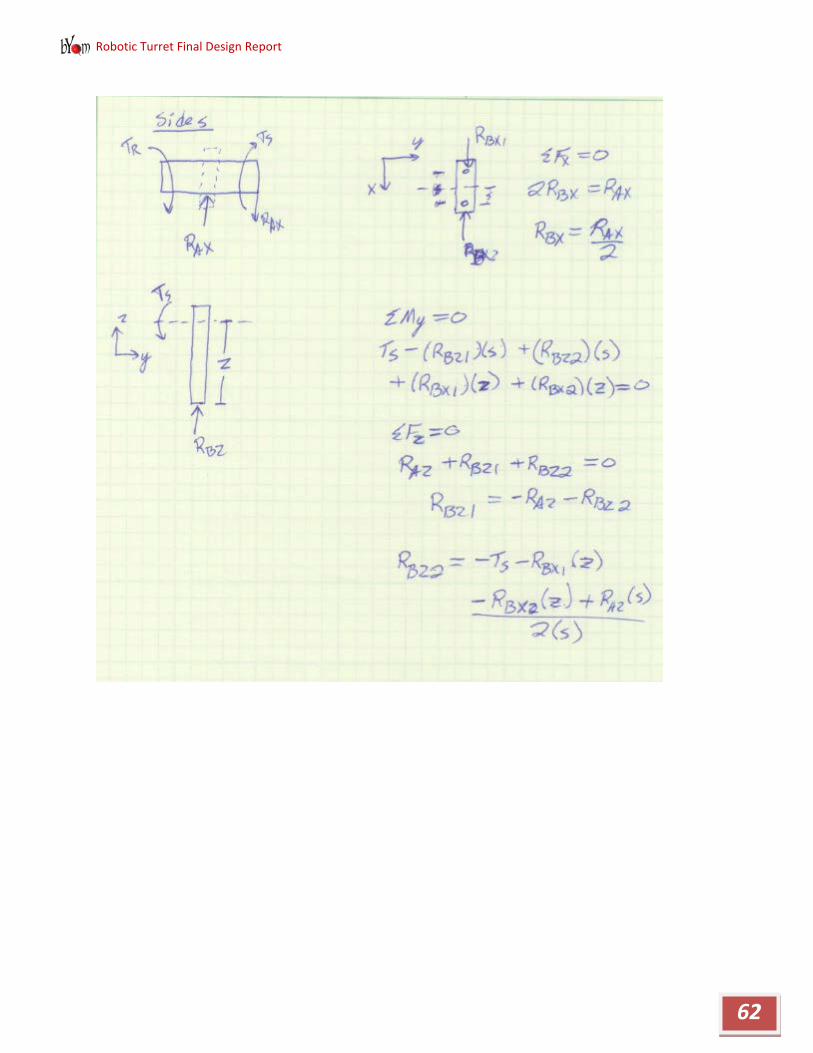
Robotic Turret Final Design Report
62

Robotic Turret Final Design Report
63

Robotic Turret Final Design Report
64

Robotic Turret Final Design Report
65

Robotic Turret Final Design Report
66

Robotic Turret Final Design Report
67
Appendix J– Connector Rod Hand Calculations

Robotic Turret Final Design Report
68

Robotic Turret Final Design Report
69
Appendix K– SolidWorks Drawings

Robotic Turret Final Design Report
70

Robotic Turret Final Design Report
71

Robotic Turret Final Design Report
72

Robotic Turret Final Design Report
73

Robotic Turret Final Design Report
74

Robotic Turret Final Design Report
75

Robotic Turret Final Design Report
76

Robotic Turret Final Design Report
77

Robotic Turret Final Design Report
78

Robotic Turret Final Design Report
79

Robotic Turret Final Design Report
80

Robotic Turret Final Design Report
81

Robotic Turret Final Design Report
82
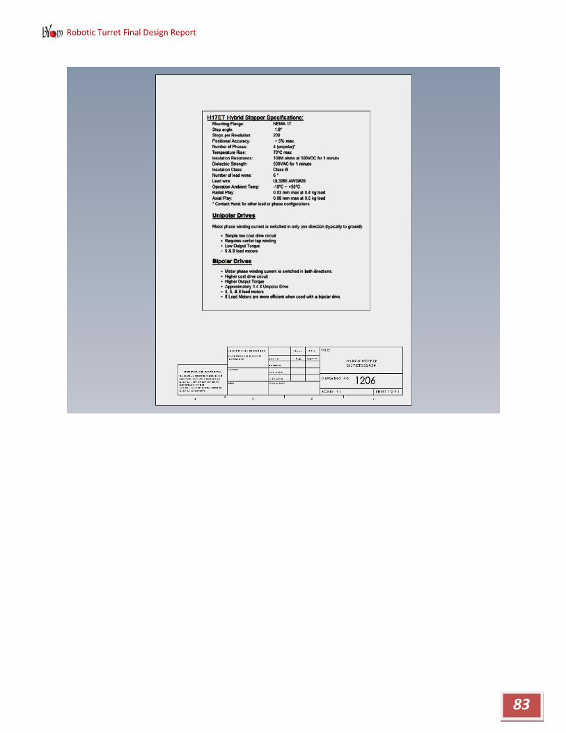
Robotic Turret Final Design Report
83

Robotic Turret Final Design Report
84

Robotic Turret Final Design Report
85

Robotic Turret Final Design Report
86

Robotic Turret Final Design Report
87

Robotic Turret Final Design Report
88

Robotic Turret Final Design Report
89

Robotic Turret Final Design Report
90

Robotic Turret Final Design Report
91

Robotic Turret Final Design Report
92

Robotic Turret Final Design Report
93

Robotic Turret Final Design Report
94

Robotic Turret Final Design Report
95

Robotic Turret Final Design Report
96

Robotic Turret Final Design Report
97

Robotic Turret Final Design Report
98

Robotic Turret Final Design Report
99

Robotic Turret Final Design Report
100

Robotic Turret Final Design Report
101

Robotic Turret Final Design Report
102

Robotic Turret Final Design Report
103

Robotic Turret Final Design Report
104

Robotic Turret Final Design Report
105
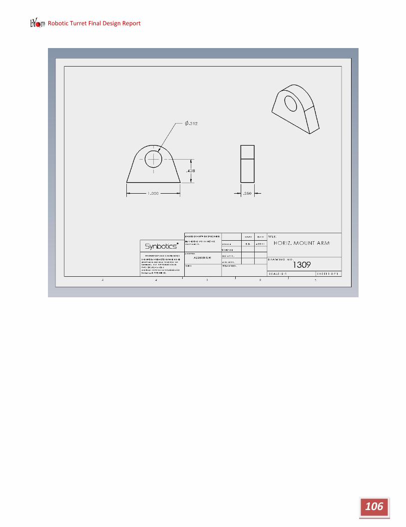
Robotic Turret Final Design Report
106

Robotic Turret Final Design Report
107

Robotic Turret Final Design Report
108
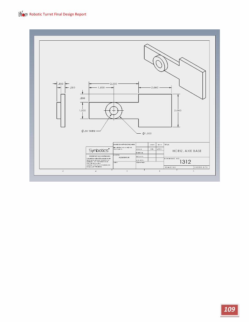
Robotic Turret Final Design Report
109

Robotic Turret Final Design Report
110

Robotic Turret Final Design Report
111

Robotic Turret Final Design Report
112

Robotic Turret Final Design Report
113

Robotic Turret Final Design Report
114

Robotic Turret Final Design Report
115

Robotic Turret Final Design Report
116

Robotic Turret Final Design Report
117

Robotic Turret Final Design Report
118

Robotic Turret Final Design Report
119

Robotic Turret Final Design Report
120

Robotic Turret Final Design Report
121

Robotic Turret Final Design Report
122

Robotic Turret Final Design Report
123
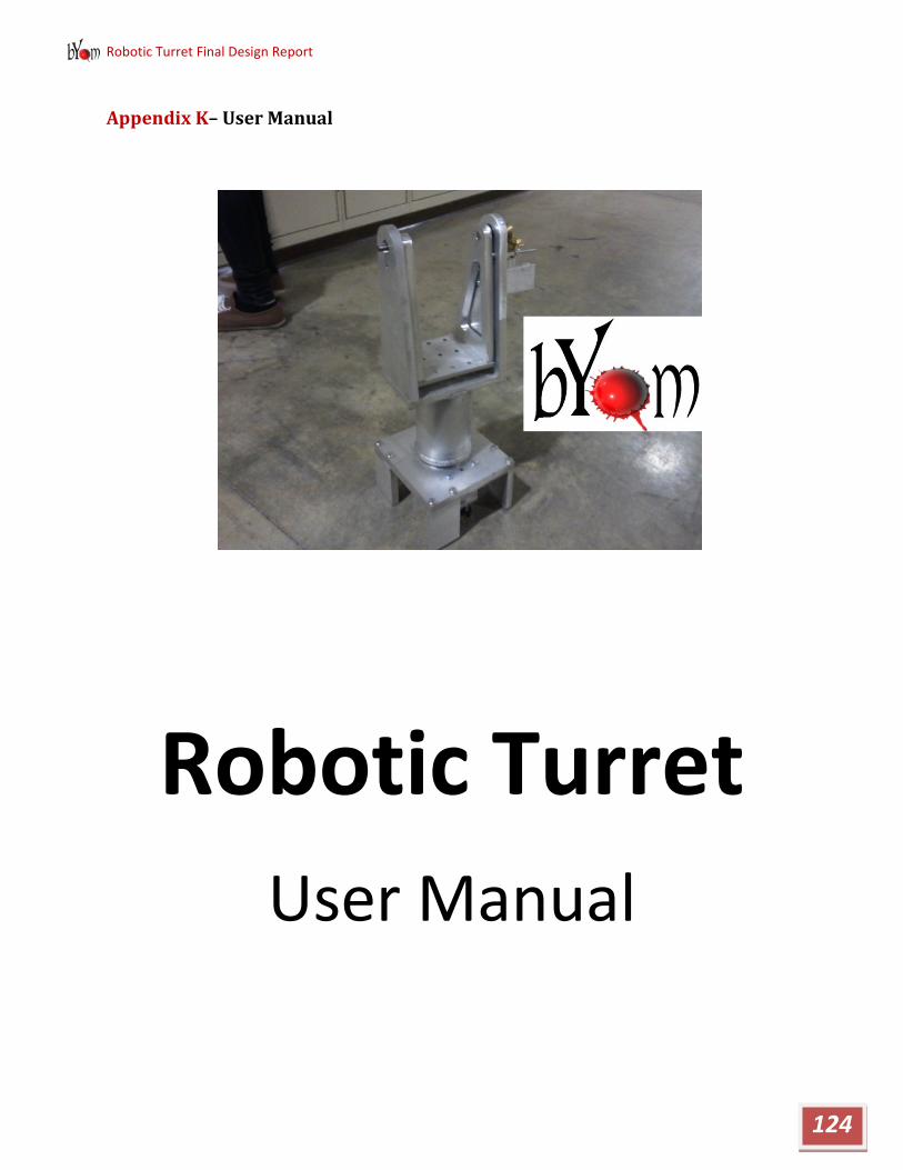
Robotic Turret Final Design Report
124
Appendix K– User Manual
Robotic Turret
User Manual

Robotic Turret Final Design Report
125
TABLE OF CONTENTS
pg. 2 – Parts
pg. 3 – Set up
pg. 4 – Running
pg. 5 – Shutdown

Robotic Turret Final Design Report
126
PARTS
Fig 1. Turret Fig 2. (Left) DC Motor Controller (Right) Stepper Controller
Robotic Turret Final Design Report
127
SET-UP
Your Turret will come with all controllers fully wired and ready to go, but there are some connections that need to be made to the computer. The program circle tracking code comes preloaded on the computer and the motor control code comes preloaded on the micro-contoller. There will be power supplies pre-wired to different boards.
• Connect the USB Webcam to a usb port on the computer. • Connect a mini-usb to the USB to Serial converter and the other end into a
usb port on the computer. • Turn on the 5V power supply which powers the micro-controller and
encoders. • Turn on the 24V power supply which powers the Stepper and DC Motors. • Power on the computer and then open up a terminal window • In the terminal type:
cd
cd workspace/TurretPC/Debug
./TurretPC
This will start the Circle Tracking program.

Robotic Turret Final Design Report
128
RUNNING
Once the program is running there will be two windows on the computer. One is the feed from the camera which will draw a circle around the found circles. The other shows where the camera has found the desired color (red) in black and white.
You can now watch the Turret track a circle. The camera is fixed and will track a circle anywhere within its field of view. In other words, if you can see the circle being found on the display on the computer, then the turret will move to aim at it.
If the Turret starts to get off track over time, you can shut off the two power supplies, put the turret at its start position and then turn the power supplies back on. This will reset the position to its home location in the program.

Robotic Turret Final Design Report
129
SHUTDOWN
1. Shut off the power supplies 2. Go back to the terminal you used to start the circle
tracking. 3. Click your cursor in the window and type CTRL-c
You can now use the computer for any other needs and put the Turret away.