robot recipes: a cookbook approach to building with vex
TRANSCRIPT

Robot Recipes: A Cookbook Approach to Building
with VexTM
Brought to you by:
Metal Gear’s 2007 Summer Build Team:
Alexa Adams, Rafi Mitri, Justin Petersen, Alan Schambers, and Ryan Schambers
Compiled by Yolande Petersen

Foreword
The VexTM Robotics Design System was made for creating designs from scratch, and experienced robot builders will find themselves in inventors’ heaven. However, builders without much experience may struggle to put together even a simple robot that actually works. Step-by-step instructions are given for one robot (the Squarebot) in the VexTM Inventor’s Guide, but trying to build unique designs beyond that can be an insurmountable challenge to builders without a foundation in basic mechanics. So far, few projects with step-by-step instructions are available. Most VexTM robot designs that are posted on the internet use parts that are not included in the basic Starter kit, but few of them tell you which ones they use. An eager builder may attempt some of these designs, only to run out of parts mid-way through the project. After a few false starts, discouragement sets in, and the kit becomes another expensive closet hog.
Having a few projects with instructions can increase a builder’s confidence and experience until s/he gets a “feel” for how the parts go together. Each project demonstrates a different mechanical principle, and together with VexTM for the Technically Challenged, can provide a basic foundation of some important engineering principles. Most of the projects (with the possible exception of the Chin-upbot) can be built in a single session of 2-3 hours, and some effort has been made to minimize the number of parts needed beyond to the Starter kit. It should be noted, however, that most “fun” projects will require additional parts. Note that the Gear Kit (containing 12, 36, 60, and 84-tooth gears) differs from the Advanced Gear Kit (containing differential, bevel gears and rack gears).
We apologize for the lean pickings of projects – some good projects got disassembled before being photographed, and other projects were pretty but non-functional (aka pretty non-functional). Our team’s robot kit has now been commandeered for competition season, so we don’t anticipate any new projects until next year.
Team Metal Gear September 2007

Table of Contents
1. Slowerbot – Introduction to gearing2. Chin-upbot – Multiple reduction gearing3. Line Follower – Sensor use4. Holonomic Drive5. Differential Swerve

Slowerbot
Level of Difficulty: 2 (1 = easiest, 5 = hardest)
Parts needed:1 Starter kit1 Gear kit (2 extra 36-tooth gears)
Pieces to cut: none
Project notesThe Slowerbot is essentially the same as the Squarebot, except that each motor is
connected to a 36-tooth gear (the same as the others), instead of the larger 60-tooth gear. Quiz question: Why would we include a project that’s almost the same as the one in the manual?
a) We couldn’t come up with enough projects and had to pad this guide to make it look longer.
b) It helps to demonstrate the principle of gear ratios.c) This project is actually a “building block” for future projects.d) All of the above.Because the gears on the motor axles are the same size as the gears on the wheel
axles, the Slowerbot’s wheels turn with the same angular velocity (spinning speed) as the motor. In contrast, the Squarebot has a larger 60-tooth gear connected to the motor (drive) axle. Thus, every time the motor makes one complete revolution, it moves through 60 teeth and drives the wheel axles through 60 teeth as well. But because the wheel axels are attached to 36-tooth gears, 60 teeth means nearly 2 rotations, not one. Thus the wheel (driven) axles turn faster than the motor (drive) axle, making the robot go faster.
There many times when going slower is desirable, especially when using sensors which need time to sense and respond to the environment. This project will be used as the driving base for the Line Follower and the Chin-upbot, and the Chin-upbot’s arm can be constructed concurrently with this project (using 2 groups of students). While it might make sense to reduce the speed even more by connecting 12-tooth gears to the motors, this does not allow sufficient spacing for even the smallest wheels to fit. Using a longer gear train is possible, but this requires using more gears and adds complexity.
Building Procedure Follow the instructions in the Inventor’s Guide for the Squarebot with the following modifications:
1. Beginning on page 2.6, position the outside plastic bearing blocks closer to the center. Rather than leaving 2 empty holes from the edge as shown in the Squarebot instructions, leave 3 empty holes as shown below.

2. On page 2.8, do not attach the 4 partially threaded beams.3. On page 2.10, continue attaching bearing blocks to the chassis rails, leaving 3
(instead of 2) empty holes between the blocks and the rail edge.4. On page 2.17, use 36-tooth gears instead of 60-tooth gears.5. On pages 2.24 and 2.25, eliminate the steps for the deck assembly.6. On page 2.26, before attaching the wheels, try to slide the 3” axles as far out as
possible. Slide on the wheels, then attach a collar to the outside. This prevents the wheels from falling off.
7. Attach the microcontroller, battery holder, and RF module wherever you like, or if you have a battery pack, attach it using the plastic strap or duct tape. (Respectable engineers don’t use duct tape, but the advantage of being a rookie is that you don’t have to be respectable).
8. Plug the motor wires into motor ports 2 and 3. Your bot is ready to go!
Programming: none (yet)
Chin-upbot
Level of Difficulty: 4
Parts needed:1 Starter Kit1 Gear Kit (4 extra 60-tooth gears)1 Metal and Hardware Kit1 Extra MotorNote: An alternative to all these add-ons to the Starter Kit is to buy a second Starter Kit.
Pieces to cut:Cut 3 X 12-inch square bars (axles) into 8” + 4” piecesCut 1 X 12-inch square bar (axle) into 2 X 6” piecesCut 3 X 15” angle bars into 2.5” + 12.5” (on the notch) – only the 2.5” pieces are used Cut 1 X 15” angle bar into 5” + 10” (on the notch) – only the 10” piece is used
Project notes:This project uses either the Squarebot or the Slowerbot as a driving base. If you
have one of these already assembled, simply remove the chassis bumper on one end and use it to build the arm. Thus, the project can be divided into 2 sub-modules (driving base and arm), so that 2 groups of students can work simultaneously. Double gearing (using 2 of the same-sized gears in each joint) is used for greater strength and to prevent stripping the gears.
Programming: None
Building ProcedureBuild the Squarebot or Slowerbot as described in the last project. Remove the chassis bumper on one end.
Construct the arm as follows:
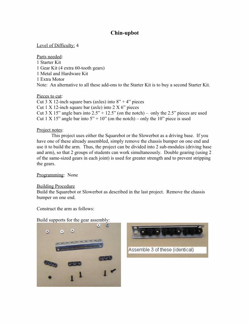
Build supports for the gear assembly:
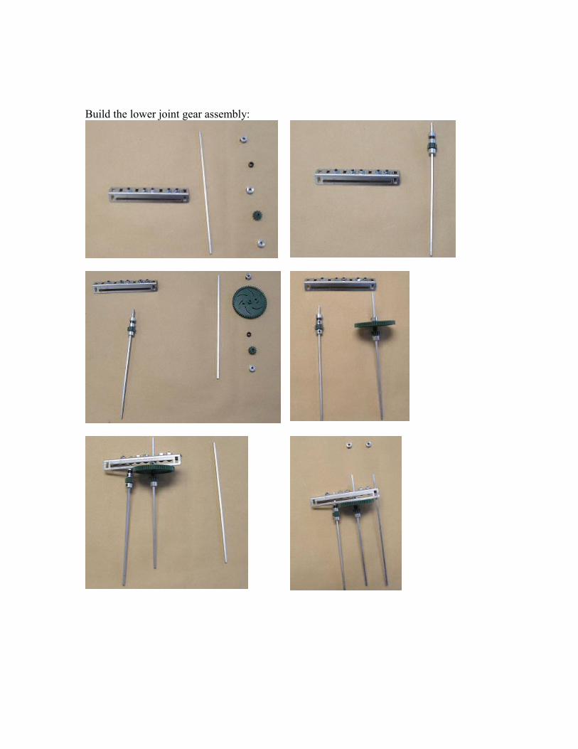
Build the lower joint gear assembly:


Add the second joint and upper arm


Attach the arm to the robot chassis. This is easier to do if the arm is folded as in the first photo in the chin-up sequence below (plug in the upper arm motor into a motor port and use the appropriate transmitter channel). Plug the drive motors into motor ports 2 and 3, and plug the arm motors into ports 5 and 6 (channels 5 and 6 are the yellow buttons located on the bottom of the transmitter).
To perform a chin-up, unfold the arm, drive the robot forward until it grabs the bar, then fold the lower hinge only to lift the robot off the ground.
Note that this robot is rather unstable (it tips easily) because of the small size of the base and high center of gravity when the arm is extended.

Programming: none

Line Follower
Level of Difficulty: 1
Parts needed: 1 Starter kit1 Programming kit1 Line Tracker kit
Pieces to cut: none
Project notes: Use the Slowerbot as the driving base, as the slower speed allows more “reaction time” for sensor readings.
Building Procedure: 1. Using a gusset, attach one of the light sensors from the line tracker kit to the chassis
bumper of the Slowerbot.
Top View Bottom view
2. Plug the sensor into Analog Input port #2.
Programming: Enter and download the following program. It uses one sensor to follow a line black line on the right side (with a turning radius of 6” or more) on white background. A threshold value of 700 was chosen for the light sensor to separate light and dark, since "light" readings ranged between 30 and 650, and "dark" readings were in the 800+ range in our setting. You may want to adjust the threshold depending on the lighting in your room.


Holonomic Drive
(original design by FVC 3053, ’06-’07, Occam’s Engineers, posted at http://www.chiefdelphi.com/media/photos/28621 and photo 28620)
Level of Difficulty: 2
Parts needed:1 Starter kit1 Metal & Hardware kit1 Extra Motor4 Omniwheels (large or small)1 Programming Kit
Pieces to cut: None
Project notes:A holonomic drive enables a robot to rotate in place, move in any direction, or do both at the same time. This bot is fairly simple to build and fun to drive. The left joystick is used to shift the robot up/down/left/right. The program included must be downloaded for the drive to work properly.
Building Procedure:Assemble the Chassis

Attach the motors
Attach supports and omniwheels
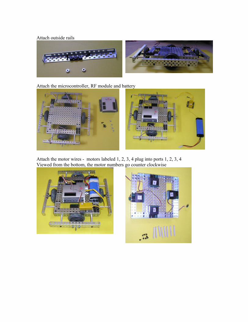
Attach outside rails
Attach the microcontroller, RF module and battery
Attach the motor wires - motors labeled 1, 2, 3, 4 plug into ports 1, 2, 3, 4Viewed from the bottom, the motor numbers go counter clockwise

Programming:The following program allows the left joystick to shift the bot up/down/left right.

Differential Swerve
(original design by FVC 3053 ’06 – ’07, Occam’s Engineers, posted athttp://www.chiefdelphi.com/media/photos/28622, and photos 28623 & 28624)
Level of Difficulty: 3
Parts needed:1 Starter Kit1 Advanced Gear Kit1 Omniwheel (small or large)
Pieces to cut:Cut one 12” square bar (axle) into two 6” piecesCut a second 12” square bar (axle) into one 4” piece + one 8” piece Cut one 15” angle bar into 10” + 5” (at the notch)Cut 2 X 15” angle bars into 12.5” + 2.5” (at the notch)
Project notes:The differential swerve is not to be confused with the differential drive, which
uses one motor on each side and uses the difference in speeds to turn – the Squarebot is an example of a differential drive. Nor is it the same as a swerve drive, which has wheels that swivel in relation to the chassis. The differential swerve uses one motor to drive forward and one motor to steer, The advantages of this over a tank drive are that it drives straight and is fairly stable on rough terrain. However, it doesn’t drive backward as easily and has a large turning radius.
This bot looks ugly as shown in the photos – some bars and axles have ends that stick out and could/should be cut off. Our team is a tightwad team, and we like to reuse parts that are already cut, even if they are a bit too big. The original design by Occam’s Engineers is more aesthetic but more complex (requiring the Chain and Sprocket kit).
Inserting the bevel gears into the differential requires a bit of force, as the lip does not allow the gears to slide in easily.
Building Procedure:
Construct the gear assembly:


Attach the wheels, building the chassis around the gear assembly.
Attach the omniwheel

Attach the microcontroller and plug the motors labeled 1 and 3 into motor ports 1 and 3, enabling the left joystick to be used for forward motion, the right stick for side-to-side motion.
Attach the RF module and battery. Voila!
Programming: none