mitsubishi robot manuals/wine...6 1. overview melfa-works is an add-in tool that runs under...
TRANSCRIPT

MITSUBISHI Mitsubishi Industrial Robot
CRn-500 Series MELFA-Works Instruction Manual
(3D-21C-WINE)
BFP-A8525-A

2
Revision History
Date of print Specifications No. Revision details 2006-11-15 BFP-A8525-* First release. 2007-02-08 BFP-A8525-A Add the following chapters.
17.3 Open MXT file 17.5 How to teach the positional calibration program 17.6 How to teach the distortion calibration program 17.9 Movement Setting Change 17.11 Change error tolerance when calibration

3
INTRODUCTION Thank you for purchasing the MELFA-Works software package for Mitsubishi Electric industrial robots. MELFA-Works is an add-in tool for SolidWorks that can be used to simulate Mitsubishi Electric industrial robots. By using MELFA-Works, it becomes possible to verify robot program operations and create processing path data. This manual describes how to perform these operations.
This product requires SolidWorks. Please note that SolidWorks needs to be provided by the customer. Refer to “2.1 Operating Environment” for supported versions.
Symbols Used in This Manual
DANGER
WARNING
CAUTION
Indicates that incorrect handling is most likely to cause hazardousconditions, resulting in death or severe injury of the operator. Indicates a possibility that incorrect handling may cause hazardousconditions, resulting in death or severe injury of the operator. Indicates that incorrect handling may cause hazardous conditions, resultingin injury of the operator, or only physical damage.
No part of this manual may be reproduced by any means or in any form, without prior consent from Mitsubishi.
The details of this manual are subject to change without notice. An effort has been made to make full descriptions in this manual. However, if any
discrepancies or unclear points are found, please contact Mitsubishi.
Microsoft, Windows are registered trademarks of Microsoft Corporation in the United States and other countries. Adobe and Acrobat are registered trademarks of Adobe Systems Incorporated. SolidWorks, PDMWorks and 3D PartStream.NET are registered trademarks of SolidWorks Corporation in the United States. Other company names and product names are trademarks or registered trademarks of the respective companies.
Copyright(C) 2006 MITSUBISHI ELECTRIC CORPORATION

4
Table of Contents 1. Overview.........................................................................................................................................................6
1.1. Basic Functions and Features.................................................................................................................7 1.2. Supported Models ...................................................................................................................................9 1.3. Version Differences ...............................................................................................................................10
1.3.1 Functional Differences ...................................................................................................................10 1.3.2 Other Differences...........................................................................................................................10
2. Preparation before Starting ..........................................................................................................................11 2.1. Operating Environment .........................................................................................................................11 2.2. Confirmation of the Product ..................................................................................................................12 2.3. Installation (MELFA-Works) ..................................................................................................................12 2.4. Installation (Calibration Tool).................................................................................................................13
3. Flow of Operations .......................................................................................................................................14 3.1. Operation Steps ....................................................................................................................................14 3.2. Flow of Robot Program Development...................................................................................................15 3.3. Flow of CAD Link System Development ...............................................................................................16
4. Creation of Parts...........................................................................................................................................17 4.1. File Formats that can be Used ..............................................................................................................17 4.2. Part Names and Marking ......................................................................................................................17 4.3. Hand Design .........................................................................................................................................18
4.3.1 Example of Part Creation 1............................................................................................................19 4.3.2 Example of Part Creation 2............................................................................................................19 4.3.3 Example of Part Creation 3............................................................................................................19
4.4. Workpiece Design .................................................................................................................................20 4.5. Travel Base Design ...............................................................................................................................20
5. Starting and Closing .....................................................................................................................................21 5.1. Starting MELFA-Works..........................................................................................................................21 5.2. Main window .........................................................................................................................................21 5.3. Creating and Loading Projects..............................................................................................................22 5.4. Saving Projects .....................................................................................................................................24
6. Robot Setting................................................................................................................................................25 6.1. Selection the robot model .....................................................................................................................26 6.2. Attaching Hands....................................................................................................................................27 6.3. Removing Hands...................................................................................................................................28 6.4. Setting Hand Input/Output Signals........................................................................................................28 6.5. Setting Travel Base ...............................................................................................................................29
7. Layout...........................................................................................................................................................31 7.1. Positioning Robots in Peripheral Device Coordinate Systems .............................................................32
8. Robot Operations .........................................................................................................................................33 8.1. Flag Setting Dialog Box.........................................................................................................................34 8.2. Movement to a Corner ..........................................................................................................................34
9. Calibration ....................................................................................................................................................35 9.1. Calibration Data Creation Procedure ....................................................................................................36 9.2. To Perform Highly Accurate Calibration ................................................................................................37
10. Creation of Work Flow..................................................................................................................................38 10.1. Creating Teaching Points ......................................................................................................................39 10.2. Path Creation ........................................................................................................................................40 10.3. Processing Setting Dialog Box..............................................................................................................41 10.4. Work Flow Creation...............................................................................................................................45
11. Virtual Controller...........................................................................................................................................47 11.1. How to Execute Programs ....................................................................................................................49 11.2. Checking Robot Interference ................................................................................................................49 11.3. Saving Simulation Moving Images........................................................................................................50 11.4. Cycle Time Measurement During Program Execution..........................................................................51 11.5. B Mode Setting......................................................................................................................................51
12. Interference Check .......................................................................................................................................52 13. Task Slots .....................................................................................................................................................53
13.1. Individual Correction of Task Slots ........................................................................................................53 13.2. Batch Correction of Task Slots ..............................................................................................................54
14. Input/Output Signal Simulation.....................................................................................................................55 14.1. Signal Monitoring ..................................................................................................................................56 14.2. Manual Signal Inputs.............................................................................................................................57 14.3. Simulation Definition Settings ...............................................................................................................58

5
14.4. Executing Signal Simulation..................................................................................................................60 14.5. Settings of Connection with GX Simulator ............................................................................................61 14.6. Connecting with GX Simulator ..............................................................................................................63
15. Step Execute/Direct Execute Dialog Box .....................................................................................................64 15.1. Step Execution ......................................................................................................................................64 15.2. Direct Execution ....................................................................................................................................65 15.3. Measurement of Cycle Time .................................................................................................................66
16. JOG Panel ....................................................................................................................................................67 17. How to Use the Calibration Tool ...................................................................................................................69
17.1. Starting ..................................................................................................................................................69 17.2. Explanation of the Calibration Tool Window..........................................................................................70 17.3. Open MXT file .......................................................................................................................................70 17.4. Executing Calibration ............................................................................................................................71 17.5. How to teach the positional calibration program (CLB.prg) ..................................................................72 17.6. How to teach the distortion calibration program(CL(dot sequence number).prg).................................72 17.7. Transferring Dot Sequence Data to Robot Controller ...........................................................................73 17.8. Managing Dot Sequence Data in Robot Controller...............................................................................74 17.9. Movement Setting Change....................................................................................................................75 17.10. Editing Output Signal Status .................................................................................................................76 17.11. Change error tolerance when calibration ..............................................................................................76
18. CAD Link Programming................................................................................................................................78 18.1. Verifying Movement Confirmation Program ..........................................................................................79 18.2. MXT Instruction (Move According to External Instruction) ....................................................................80 18.3. P_MXT Variable ....................................................................................................................................81 18.4. Precautions ...........................................................................................................................................82

6
1. Overview MELFA-Works is an add-in tool that runs under SolidWorks, used for simulating production systems using robots on personal computers, converting processing paths defined for workpieces to data and outputting this data. MELFA-Works also contains a calibration tool for correcting previously created processing path data and transferring such data to the controller, and RT ToolBox (mini) for creating programs and changing parameters.
Since MELFA-Works is an add-in tool for SolidWorks, it is possible to make use of peripheral devices and parts such as hands created using SolidWorks as is.
Fig. 1-1 Product Configuration
* Robot controllers of system version K8 and later support the enhancing memory
The figure below illustrates a block diagram showing the components included in MELFA-Works and the environment in which each of them operates.
Fig. 1-2 Product Block Diagram
RT ToolBox(mini)
Calibration tool
Processing path data Calibration data
MELFA-Works
Virtual controller
SolidWorks
MELFA-Works
Windows XP/2000
SolidWorks
RT ToolBox(mini) Calibration tool MELFA-Works add-in tool
Actual robot (memory expansion
recommended*)

7
1.1. Basic Functions and Features
The table below describes the basic functions and features of MELFA-Works.
Function Feature 1 Robot model setting This function allows selecting a model name from a displayed list
and setting the robot model. A robot can be placed using positions relative to the CAD origin or other parts. Layout setting via value entry is also possible. * See “Table 1-1 Robots that can be Used” for robots supported by
this software.
2 Attaching hands This function allows attaching hands designed and created using SolidWorks to a robot. It is also possible to specify ATC (Auto Tool Changer).
3 Travel axis This function allows attaching a travel axis to a robot to verify system operations with a travel axis.
4 Loading and changing layout of peripheral devices
This function allows loading peripheral devices configured with SolidWorks parts. Loaded parts can be placed using positions relative to the CAD origin as well as other parts. Layout change via value entry is also possible.
5 Workpiece handling It is possible to handle workpieces by simulating hand signals with robot programs. Note that it is necessary to set workpiece names according to the naming convention in order to handle the signals.
6 CAD link This function allows creating data necessary for operations that would otherwise require large amounts of teaching, such as laser welding, sealing and other operations involving tracing some parts on a workpiece, simply by selecting processing parts from 3-dimensional CAD data. Since data is created based on 3-dimensional CAD data, it is possible to handle complicated, 3-dimensional curves and the man-hours required for the teaching can also be reduced significantly. * Only 6-axis robots support this function. See “Table 1-1 Robots
that can be Used” for the details. * This function supports the MELFA-BASIC language only.
7 Specification of robot program
With this function, it is possible to use programs used with actual robots as is. Also, in the same way as with an actual controller, it is possible to specify a robot program for each task slot.
8
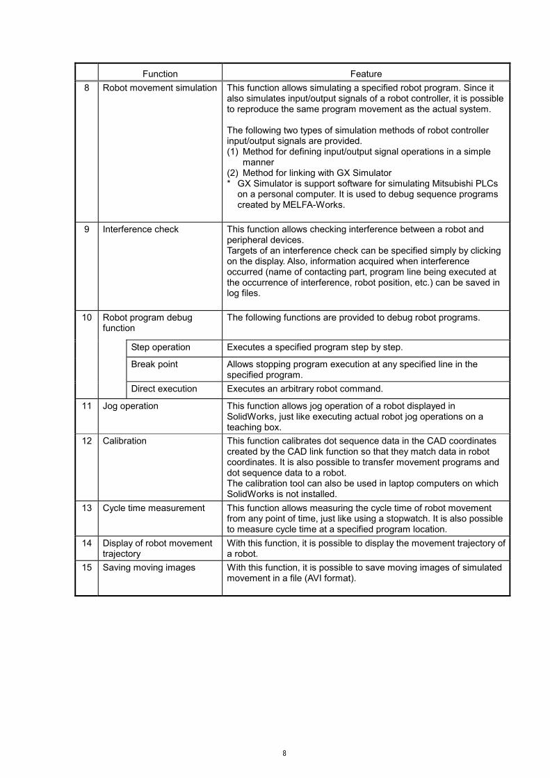
Function Feature 8 Robot movement simulation This function allows simulating a specified robot program. Since it
also simulates input/output signals of a robot controller, it is possible to reproduce the same program movement as the actual system. The following two types of simulation methods of robot controller input/output signals are provided. (1) Method for defining input/output signal operations in a simple
manner (2) Method for linking with GX Simulator * GX Simulator is support software for simulating Mitsubishi PLCs
on a personal computer. It is used to debug sequence programs created by MELFA-Works.
9 Interference check This function allows checking interference between a robot and
peripheral devices. Targets of an interference check can be specified simply by clicking on the display. Also, information acquired when interference occurred (name of contacting part, program line being executed at the occurrence of interference, robot position, etc.) can be saved in log files.
10
Robot program debug function
The following functions are provided to debug robot programs.
Step operation Executes a specified program step by step.
Break point Allows stopping program execution at any specified line in the specified program.
Direct execution Executes an arbitrary robot command.
11 Jog operation This function allows jog operation of a robot displayed in SolidWorks, just like executing actual robot jog operations on a teaching box.
12 Calibration This function calibrates dot sequence data in the CAD coordinates created by the CAD link function so that they match data in robot coordinates. It is also possible to transfer movement programs and dot sequence data to a robot. The calibration tool can also be used in laptop computers on which SolidWorks is not installed.
13 Cycle time measurement This function allows measuring the cycle time of robot movement from any point of time, just like using a stopwatch. It is also possible to measure cycle time at a specified program location.
14 Display of robot movement trajectory
With this function, it is possible to display the movement trajectory of a robot.
15 Saving moving images With this function, it is possible to save moving images of simulated movement in a file (AVI format).

9
1.2. Supported Models The table below lists models supported in MELFA-Works.
Table 1-1 Robots that can be Used
Robot Function Simulation CAD link
RV-3S RV-3SJ × RV-6S RV-6SL RV-12S
RV series
RV-12SL RH-6SH3520 × RH-6SH4520 × RH-6SH5520 × RH-12SH5535 × RH-12SH7035 × RH-12SH8535 ×
RH-SH series
RH-18SH8535 × RP-1AH × RP-3AH ×
RP series
RP-5AH ×

10
1.3. Version Differences This section explains differences between version 1 and version 2.
1.3.1 Functional Differences
Table 1-2 Functional Differences No. Function Version 1 Version 2 Remark 1 Robot model setting Improved operation
dialog box 2 Attaching hands Improved operation
dialog box 3 Travel axis Improved operation
dialog box 4 Loading and changing layout of
peripheral devices Improved operation
dialog box 5 Actual workpiece handling Improved operation
dialog box 6 Virtual workpiece handling × Deleted 7 CAD link Improved operation
dialog box 8 Specification of robot program Improved operation
dialog box 9 Robot movement simulation 10 Interference check 11 Robot program debugging 12 Jog operation 13 Calibration Improved
operability 14 Cycle time measurement 15 Display of robot movement
trajectory
16 Saving moving images 17 Offline teaching × Newly added 18 Work flow creation × Newly added 19 Distortion calibration
(calibration tool) × Newly added
20 Project management Improved operability
21 Loading layout (assembly) × Newly added
1.3.2 Other Differences
Table 1-3 Other Differences No. Item Version 1 → 2 1 Dialog boxes/windows Changed/improved. 2 Path data carry-over It is no longer necessary to register paths again
when changing hands. 3 Performance improvement The speed of checking path while moving has been
improved. 4 Project management It is now possible to switch between projects without
closing the application.

11
2. Preparation before Starting
2.1. Operating Environment
The table below shows the specifications of the operating environment of MELFA-Works and the personal computer on which the calibration tool runs. The calibration tool is designed such that it runs comfortably on a laptop computer.
Table 2-1 MELFA-Works Operating Environment Item Minimum Requirement Recommended
CPU Refer to the recommended SolidWorks environment. *1 Main memory Refer to the recommended SolidWorks environment. *1
Graphic display XGA (1024x768) or more SXGA (1280x1024) or more Video card installed *1
Hard disk 1 GB or more free space Disk device CD-ROM drive
Pointing device Must operate in Microsoft Windows® environment With wheel button
Keyboard PC/AT compatible keyboard
OS Microsoft Windows® 2000 Professional SP4 Microsoft Windows® XP Professional (32-bit) SP2
3D-CAD
SolidWorks® 2004 SP4.1 or later SolidWorks® 2005 SP5.0 SolidWorks® 2006 SP4.1 or later SolidWorks® 2007 SP0.0 * Due to the specifications of SolidWorks, it is not possible to migrate
data created by a later version to an earlier version.
External application
GX Simulator Version 7 * Used to simulate input/output signals using ladder programs. RT ToolBox (Standard version) must not be installed. * When you install MELFA-Works, RT ToolBox mini is installed
automatically at the same time. MELFA-Works and RT ToolBox (Standard version) cannot be installed on the same personal computer.
Table 2-2 Calibration Tool Operating Environment
Item Recommended CPU 1.0 GHz or faster Intel Pentium4 or compatible processor Main memory 256 MB or more Graphic display XGA (1024x768) or more Hard disk 100 MB or more free space Disk device CD-ROM drive
Pointing device Must operate in Microsoft Windows® environment With wheel button
Keyboard PC/AT compatible keyboard
OS Windows® 2000 Windows® XP Professional
3D-CAD Not required Note: The calibration tool can be operated independently from MELFA-Works. *1 For the recommended SolidWorks operating environment, please refer to
http://www.solidworks.com/pages/services/SystemRequirements.html

12
2.2. Confirmation of the Product (1) Confirmation of Package
Check that the following items are included in the package. CD-ROM “MELFA-Works” Setup Guide Software License Agreement License Certification (Please make sure that the product name and product ID are printed on it.)
* If any item is missing, please contact the branch office or distributor from which you purchased the product.
(2) Confirmation of CD-ROM
The data on the CD-ROM has the following structure.
Setup.exe
Other setup files
MELFA-Works (MELFA-Works installation file)
Setup.exe
Other setup files
Calibration (Calibration tool installation file)
BFP-A8525.PDF (This manual)
Doc (Instruction manual for this software)
BFP-A8090.PDF (RT ToolBox Instruction Manual)
Form (User Registration Application Form)
Misc (Other files)
Address.pdf (MELSOFT User Registration Application Form, address stick-on form)
Fax.pdf (MELSOFT User Registration Application Form, Fax transmission form)
[Drive name]:\
AutoRun.inf
2.3. Installation (MELFA-Works) This section explains how to install the software.
(1) Insert the product in the personal computer’s CD-ROM drive; the setup dialog box automatically appears.
(2) If the setup dialog box does not appear when you insert the product in the CD-ROM drive, display the
setup dialog box according to the following procedure. Click the [Start] button and then select [Run...]. Check the CD-ROM drive name and enter "drive name":
\MELFA-Works\Setup.exe (e.g., if the CD-ROM drive is "D:," type “D:\MELFA-Works\Setup.exe”).
Fig. 2-1 Run
13
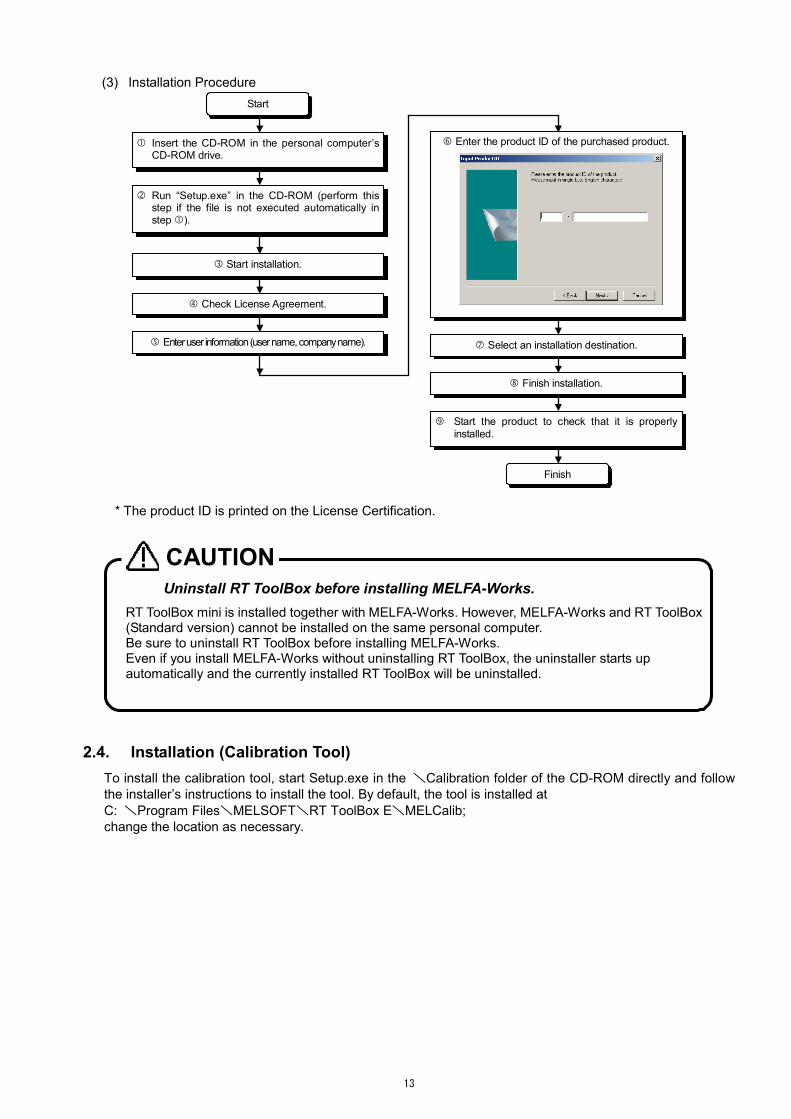
(3) Installation Procedure Start
Enter the product ID of the purchased product.
Start the product to check that it is properly installed.
Finish installation.
Finish
Insert the CD-ROM in the personal computer’s CD-ROM drive.
Run “Setup.exe” in the CD-ROM (perform thisstep if the file is not executed automatically instep ).
Select an installation destination.
Start installation.
Check License Agreement.
Enter user information (user name, company name).
* The product ID is printed on the License Certification.
Uninstall RT ToolBox before installing MELFA-Works. RT ToolBox mini is installed together with MELFA-Works. However, MELFA-Works and RT ToolBox (Standard version) cannot be installed on the same personal computer. Be sure to uninstall RT ToolBox before installing MELFA-Works. Even if you install MELFA-Works without uninstalling RT ToolBox, the uninstaller starts up automatically and the currently installed RT ToolBox will be uninstalled.
CAUTION
2.4. Installation (Calibration Tool) To install the calibration tool, start Setup.exe in the \Calibration folder of the CD-ROM directly and follow the installer’s instructions to install the tool. By default, the tool is installed at C: \Program Files\MELSOFT\RT ToolBox E\MELCalib; change the location as necessary.

14
3. Flow of Operations This chapter explains the flow of operations involved in starting up a system using MELFA-Works, up to operating a robot in its actual environment. The specific operations that can be carried out in each dialog box/window are explained in the subsequent chapters; refer to the corresponding chapter for further details.
3.1. Operation Steps Several operations are involved in constructing a system using MELFA-Works. They can largely be divided into the following 4 steps.
Table 3-1 Operation Steps Using “SolidWorks” Create workpieces, hands and other parts in SolidWorks
and convert other CAD data to mark for MELFA-Works.
Using “MELFA-Works” Use MELFA-Works to specify processing locations, intermediate postures and various parameters to eventually create template robot programs, dot sequence data and calibration programs.
Using “calibration tool” Use the calibration tool to calibrate dot sequence data to processing positions of workpieces in the actual space. Download the calibrated dot sequence data to a robot controller.
Using “RT ToolBox” Use RT ToolBox to create programs that are operable in actual systems based on the template programs created in step . Debug the created operational programs.

15
3.2. Flow of Robot Program Development This section explains how to develop robot programs without using the CAD link function. Refer to the corresponding chapter for further details. The numbers to to the left of each of the items indicate the operation steps explained in “Chapter3.1 Operation Steps”.
Create parts required for simulation
Create workpieces, hands and other parts in SolidWorks. “Chapter4 Creation of Parts”
↓
Create a project Create a new project or load an existing project. “Chapter5 Starting and Closing”
↓
Load a robot Load a robot by selecting from a list. “Chapter6 Robot Setting”
↓
Attach hands Attach hands (fixed hands, ATC) to the robot. It is also
possible to make signal settings for simulation. ”Chapter6 Robot Setting”
↓
Mount on travel base Mount the robot on a travel base. Moving direction and target axes are set here as well. ”Chapter6 Robot Setting”
↓
Place peripheral devices Place loaded peripheral devices in arbitrary positions. ”Chapter 7 Layout”
↓
Place robot Place the loaded robot to an arbitrary location. ”Chapter 7 Layout”
↓ Change posture Change the robot posture. ”Chapter 8 Robot Operations” ↓
Teach posture Teach the robot postures of operations. ”Chapter 10 Creation of Work Flow”
↓
Create work flow Specify the work flow by combining teaching points and paths. “Chapter 10 Creation of Work Flow”
↓
Create a program Create a robot movement program based on a work flow. “Chapter 10 Creation of Work Flow”
↓
Check movement with a virtual controller
Using a virtual controller allows checking the movement in advance. ”Chapter 11 Virtual Controller”
↓
Create an operational
program
Modify an automatically created program according to your specific system using RT ToolBox. ”Chapter 18 CAD Link Programming”

16
3.3. Flow of CAD Link System Development This section explains the flow of development of robot programs using the CAD link function. The numbers
to to the left of each of the items indicate the operation steps explained in “3.1 Operation Steps”.
Create parts required for simulation
Create workpieces, hands and other parts in SolidWorks. “Chapter4 Creation of Parts”
↓
Create a project Create a new project or load an existing project. “Chapter5 Starting and Closing”
↓ Load a robot Load a robot by selecting from a list. “Chapter6 Robot Setting” ↓
Attach hands Attach hands (fixed hands, ATC) to the robot. It is also possible
to make signal settings for simulation. ”Chapter6 Robot Setting”
↓
Mount on travel base Mount the robot on a travel base. Moving direction and target axes are set here as well. ”Chapter6 Robot Setting”
↓
Place peripheral devices Place loaded peripheral devices in arbitrary positions. ”Chapter 7 Layout”
↓
Place robot Place the loaded robot to an arbitrary location. ”Chapter 7 Layout”
↓ Change posture Change the robot posture. ” Chapter 8 Robot Operations” ↓
Create calibration data Specify reference points used in the operation. “Chapter 9 Calibration”
↓
Teach posture Teach the robot postures of operations. ”Chapter 10 Creation of Work Flow”
↓
Create work flow Specify the work flow by combining teaching points and paths. ”Chapter 10 Creation of Work Flow”
↓
Create a program Create a robot movement program based on a work flow. ”Chapter 10 Creation of Work Flow”
↓
Check movement with a virtual controller
Using a virtual controller allows checking the movement in advance. ”Chapter 11 Virtual Controller”
↓
Teach calibration points Transfer the calibration program to the controller in order to teach the robot. “Chapter 17 How to Use the Calibration Tool”
↓
Calibrate dot sequence
and transfer to controller
Perform calibration using the teaching result and transfer the calibrated dot sequence data to the controller. “Chapter 17 How to Use the Calibration Tool”
↓
Create an operational
program
Modify an automatically created program according to your specific system using RT ToolBox. ”Chapter 18 CAD Link Programming”

17
4. Creation of Parts
With MELFA-Works, parts created by customers can be used as hands or workpieces. When attaching hands or similar on a robot and handling workpieces, such parts should be created in advance by following the creation rules explained in this chapter. The operations mentioned above are not required to simply operate a robot. Sample data for hands, workpieces, travel bases and so forth can be found in the sample folder; please make use of them as reference.
4.1. File Formats that can be Used MELFA-Works is able to use data created by other CAD software as far as the data is stored using file formats that can be loaded by SolidWorks. In this case, the files should be converted into sldprt format before loading the data. File formats that can be converted conform to SolidWorks. Currently, the following file formats are supported.
Table 4-1 Supported File Formats IGES Unigraphics STEP PAR (Solid EdgeTM) SAT (ACISR) IPT (Autodesk Inventor) ParasolidR Mechanical Desktop DWG CADKEYR DXFTM Viewpoint STL RealityWave VRML HOOPS VDA-FS CGR (CATIARgraphics) Pro/ENGINEERR HCG (Highly compressed graphic)
* Please check the latest specifications at the Website of SolidWorks Corporation.
4.2. Part Names and Marking The main part types used in MELFA-Works include robot components, hands, travel bases, workpieces and other peripheral devices. Among these, some parts are handled in a special manner by MELFA-Works, and several rules thus apply. The rules can mainly be categorized into the following two types.
Part Names Part names loaded in SolidWorks, which correspond to file names, are used to distinguish whether
the part is a hand, workpiece or something else. Insert “_identifier’’ before the file extension as a character string that distinguishes among parts, as in the following example.
(Example) Sample_identifier.sldprt
Marking In order to have a reference frame for connecting parts, such as a robot and a hand or a hand and a
workpiece, a “coordinate system” with a specific name must be embedded in a part.

18
Table 4-2 Rules in Parts Creation Part name Format of part name
(= file name) First origin (for connecting robot)
Second origin (for connecting workpieces)
Fixed hand Arbitrary character string + “_Hand.sldprt" (Example) Sample_Hand.sldprt
ATC tool Arbitrary character string + “_ToolATC.sldprt" (Example) Sample_ToolATC.sldprt
Coordinate system: Orig1
In the case of gripping hands Coordinate system: Pick1 to 8 * Set to gripping area In the case of processing hands Coordinate system: Orig2 * Set to processing point
ATC master Arbitrary character string + “_MasterATC.sldprt" (Example) Sample_MasterATC.sldprt
Coordinate system: Orig1
Coordinate system: Orig2
Workpiece Arbitrary character string + “_Work.sldprt" (Example) Sample_Work.sldprt
Coordinate system: Orig1 * Set to gripping area(Can be omitted)
None
Travel base Arbitrary character string + “.sldprt" (Example) Sample.sldprt
Coordinate system: Arbitrary (Multiple coordinate systems can be used.)
None
Orig1 or 2: Used to connect of parts in front and back. The second origin of a part in front and the first origin of a part in back match, for example Orig2 of J6 axis of a 6-axis robot and Orig1 of a fixed hand, as well as Orig1 of the ATC master and Orig2 of the ATC tool.
Pick1 to 8: Used to determine the position of a gripped workpiece.
* You should save parts as a solid model if it targets it in the interference check.
4.3. Hand Design MELFA-Works can handle the following hands.
Table 4-3 Hands that can be Used Type Explanation
Fixed hand Fixed hands are directly attached to a flange.
ATC master The master side of ATC (Auto Tool Changer). The ATC master part is directly attached to a flange. The ATC tool can be removed or attached according to commands issued via robot input/output signals. In order to attach the tool via a signal, the ATC tool must be in the vicinity of the robot (no more than 100 mm away).
ATC tool The tool side of ATC. The ATC tool side is fixed to the ATC master.
Two types of hand applications, gripping hands and processing hands, can also be handled by this software. These types of hand applications are defined as follows.
Table 4-4 Hand Applications
Type Explanation
Gripping hand
A gripping hand is used to handle workpieces. Up to 8 gripping areas can be set for each hand and it is possible to grip up to 8 workpieces at the same time. A marking (Pick 1 to 8) is required for each gripping area.
Processing hand
A processing hand is used in laser welding, sealing and other operations that involve tracing of specific locations on a workpiece. A marking (Orig2) is required for the hand processing point.

19
4.3.1 Example of Part Creation 1 In order to allow MELFA-Works to handle a part, the part name, first origin and second origin must be specified according to the rules shown in “Table 4-2 Rules in Parts Creation”.
First origin: For connecting with a part closer to the robot origin (part in front) Second origin: For connecting with a part farther from the robot origin (part in back)
Fig. 4-1 Example of Part Creation 1 (In the Case of ATC Master)
4.3.2 Example of Part Creation 2 As a rule, the coordinate system (Orig*) is set such that the direction away from the robot origin is defined as +Z. If the coordinate system is set in the opposite direction, the direction of connection is also reversed.
ATC master ATC tool
Joint area Gripping area
Fig. 4-2 Example of Part Creation 2 (In the Case of ATC Tool)
4.3.3 Example of Part Creation 3
Fig. 4-3 Entire Hand
First origin (robot side)
Second origin (tool side)
Orientation of the coordinate system Y
X
Z
Y
X
Z
Orig1
Y
X
Z
Pick1 Y
X
Z
Orig2

20
Fig. 4-4 Robot Joint Area Fig. 4-5 Hand Processing Area
4.4. Workpiece Design * The “workpieces” explained here are items gripped by a hand. There is no need to identify parts that are
not gripped as “workpieces.” In order for a part to be recognized as a workpiece, append the character string "_Work" to the part name according to the parts creation rules. Also, place an "Orig1" marking if the gripping posture is determined.
Fig. 4-6 Example of Workpiece Creation
4.5. Travel Base Design In order for a part to be recognized as a travel base, place a marking (with an arbitrary name) indicating the origin of the travel base. It is also possible to allocate several robots by placing multiple markings on one travel base.
Fig. 4-7 Example of Travel Base Creation

21
5. Starting and Closing 5.1. Starting MELFA-Works
Start SolidWorks from the [Start] menu of Windows. After starting SolidWorks, select [Start] from the [MELFA-Works] menu to start MELFA-Works.
Fig. 5-1 Starting MELFA-Works
5.2. Main window
The MELFA-Works Main window provides project operation functions as well as functions for starting various function dialog boxes and switching path displays. By clicking the appropriate function button, the corresponding dialog box for performing robot settings, layout changes, robot operations, calibration, work flow creation, virtual controller control or interference check appears. By clicking the trajectory display buttons, it is also possible to switch between trajectory display ON and OFF or to delete previously displayed paths.
Fig. 5-2 Main Window
Table 5-1 Operations Provided by the Main Window Robot setting Change settings of robot model, travel base, hand and so on. Layout Place the robot and peripheral devices. Robot operation Change robot postures. Calibration Edit calibration data. Work-flow Edit robot movement points, path and flow. Virtual controller Operate the virtual controller. Trajectory display Switch between erace trajectories(left button) and showing/hiding
trajectories(right button). Check interference Check whether or not a robot, hand, tool, workpiece, etc. are interfering.
Trajectory display buttons
Various function buttons
22
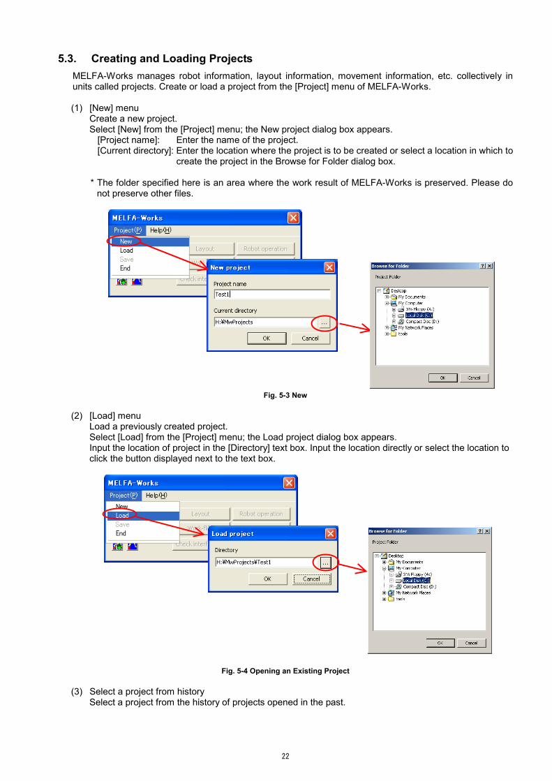
5.3. Creating and Loading Projects MELFA-Works manages robot information, layout information, movement information, etc. collectively in units called projects. Create or load a project from the [Project] menu of MELFA-Works.
(1) [New] menu
Create a new project. Select [New] from the [Project] menu; the New project dialog box appears.
[Project name]: Enter the name of the project. [Current directory]: Enter the location where the project is to be created or select a location in which to
create the project in the Browse for Folder dialog box.
* The folder specified here is an area where the work result of MELFA-Works is preserved. Please do not preserve other files.
Fig. 5-3 New
(2) [Load] menu
Load a previously created project. Select [Load] from the [Project] menu; the Load project dialog box appears. Input the location of project in the [Directory] text box. Input the location directly or select the location to click the button displayed next to the text box.
Fig. 5-4 Opening an Existing Project
(3) Select a project from history Select a project from the history of projects opened in the past.

23
If you select the [Project] menu, up to 10 projects that have been opened recently in MELFA-Works are displayed at the bottom of the menu; select a project.
Up to 10 recently openedprojects are displayed.
Fig. 5-5 Selecting from History

24
5.4. Saving Projects To save a project, select [Save] from the [Project] menu. The project management message confirming whether or not to save the project appears; click an appropriate button. The project management message confirming whether or not to save the project appears when closing MELFA-Works as well.
Fig. 5−6 Saving Projects

25
6. Robot Setting In MELFA-Works, it is possible to set up to 2 robots of the types indicated in “Table 1-1 Robots that can be Used”. In the Robot setting dialog box explained in this chapter, it is possible to load robots, attach and remove hands and travel bases to/from each robot and make hand signal settings to be used in simulation.
In order to make robot settings, double-click a target robot from the list in the Robot setting dialog box, or select a robot and then click the [Change] button, to display the Robot details setting dialog box.
Fig. 6-1 Robot Setting
Layout after selecting a robot model is performed in the Layout dialog box, which is explained in Chapter 7.

26
6.1. Selection the robot model Select the robot model in the following procedure. Click the [Robot setting] button from the Main window to display the Robot setting dialog box. Select a
robot for which model setting is to be made from the list and click the [Change] button.
The Robot details setting dialog box appears; select a robot model from the pull down menu.
A confirmation message is displayed. If the model is correct, click [Yes] to load the robot.
Fig. 6-2 Robot Model Setting
When using 2 robots, change the layout of one robot at a time. If you are using 2 robots, make sure to load peripheral devices first and then position the robots one at a time, as robots, both mechanisms 1 and 2, are positioned with respect to the CAD origins when they are loaded. This way, the tasks can be carried out easily. See the next chapter for how to change layouts.
Tips

27
6.2. Attaching Hands Attach hands to a robot. Note that parts must adhere to several rules in order for them to be used as hands. See “Chapter 4 Creation of Parts" for the details. Load hands to be attached in advance by dragging and dropping them onto SolidWorks window, or using other method. There are the following two ways to attach hands. Method 1: Select a hand in SolidWorks and click the [Connect] button.
Fixed hands and ATCs are automatically identified and attached.
If a hand has already been attached, it is removed.
Fig. 6-3 Attaching Hand 1
Method 2: Select the [Hand] text box and click a hand part.
Only the specified type of hand is attached. If a hand has already been attached, it is removed.
Fig. 6-4 Attaching Hand 2
Click the hand.
Click [Connect].
Click the hand.
Click the [Hand] text box.
Load a hand part.
The hand moves, and it is connected with the robot.
The hand moves, and it is connected with the robot.

28
6.3. Removing Hands The hand currently attached to robots is removed by clicking the [Disconnect] button.
If an ATC master and ATC tool are mounted, they are removed in the order of the ATC tool first and then the ATC master with each click of the [Disconnect] button.
Fig. 6-5 Removing Hand 6.4. Setting Hand Input/Output Signals
When simulating a robot program, MELFA-Works also allows simulating movement in the vicinity of the hands, such as ATC attachment/removal and workpiece grip/release. These movements can be controlled by input/output signals of the virtual controller and signals and movements around hands can be associated in the Hand I/O dialog box. Click the [Signal setting] button in the Robot details setting dialog box to display the Hand I/O dialog box.
Fig. 6-6 Hand I/O Dialog Box
Table 6-1 Details of Operation in the Dialog Box
No
Specify a signal number. Specification of -1 means not set. [ATC]: Connected signal of the ATC master and ATC tool. [Pick*]: Connected signal of a gripping hand and workpieces. * Attaches/grips at a rising edge and removes/releases at a falling edge.
Click [Disconnect].
The ATC master is removed.
The ATC tool is removed.

29
IN/OUT
Select either input signal or output signal for a robot. IN: Simulates changes of an input to a robot, i.e., M_IN(n). Corresponds to
cases where an external device (PLC, etc.) controls the robot hand. OUT: Simulates changes of an output from a robot, i.e., M_OUT(n). Corresponds
to cases where the robot hand is controlled by a robot program.
/
Simulate turning a signal ON/OFF. : Indicates that the hand is attached. Click the button in this display
status to simulate removal of the hand.
: Indicates that the hand is removed. Click the button in this display status to simulate attachment of the hand.
In hand attachment operations, ATC tools in the vicinity of the ATC
master and workpieces in the vicinity of a gripping hand (within 100 mm) are attached/gripped. If the action succeeds, the status changes to the status.
* If a signal number has not been specified, neither attachment nor removal is
simulated.
Posture maintenance
Specify whether or not to maintain the posture at gripping. Maintain : Maintains the gripping posture and move. Do not maintain : Grips such that the hand’s PickN and the Orig1 coordinate system
of a workpiece are matched at gripping. It is possible to take a fixed gripping posture regardless of the gripping position.
6.5. Setting Travel Base
MELFA-Works allows placing a robot on a travel axis created in SolidWorks and moving it with a robot program or robot operation. The travel location can be specified either by “relative position” with the coordinate system on a part as the origin or “absolute position” with coordinates on the CAD coordinate system as the origin. Load a travel base part into an assembly and use the following dialog box to make travel base settings.
Travel axis origin position
Direction of movement
Direction of layout
Reference axis
Fig. 6-7 Travel Base Setting Section

30
Table 6-2 Details of Operation in the Dialog Box Origin pos Click and select the field and click the coordinate system specified
for the travel base. Enter coordinate values directly to set an absolute coordinate system.
Direction of movement Specify in which direction of the coordinate system set for the travel axis origin the axis moves if the reference axis moves in the positive direction. Make selection from +X, -X, +Y and -Y (default value: +Y).
Direction of layout Specify the orientation of the robot with respect to the coordinate system set for the travel axis origin. Make selection from 0, 90, 180 and -90 degrees (default value: 0 degrees).
Reference axis Specify which axis of the robot is set as the travel axis. Make selection from Nothing, J7 and J8 axes (default value: Nothing).

31
7. Layout With MELFA-Works, it is possible to use the Layout dialog box to specify positions of robots and peripheral devices such as travel bases relative to the CAD software origin as well as robot origin, part origin and arbitrary coordinate systems. Specify layout by specifying positions relative to the base position. The base position can be selected from the following 4 types.
Origin Origin of other robots Origin of other parts Coordinate system
Fig. 7-1 Changing Robot Layout
Layout changes are achieved by the following procedure. Click the [Layout] button from the Main window to display the Layout dialog box. Select the [Target] text box and click a robot, peripheral device, etc. to display the name of the robot or
part you selected in the [Target] text box. Select the base position. If you select a position other than an origin, click the [Base Pos] text box and
click the robot, part or coordinate system. In the same way as for the [Target] text box, the selected name is set in the [Base Pos] text box.
Operate in the Operation area to determine the position. � It is also possible to load layout data by clicking the [Load Layout] button.
A robot placed on a travel base must move the travel base. A robot placed on a travel base cannot be moved because its position relationship with the travelbase is fixed. In this case, specify the travel base as the target of movement to move the robot along with the base.
CAUTION
After loading peripheral devices, let’s place a robot. It is possible to work efficiently by create the coordinate system on the peripheral devicesbeforehand, and place the robot in the coordinate system.
Tips
[Base Pos] text box
[Target] text box
Operation area

32
7.1. Positioning Robots in Peripheral Device Coordinate Systems Follow the procedure below to position a robot in a coordinate system of a peripheral device.
Display the appropriate coordinate system via the menus of SolidWorks.
Fig. 7-2 Coordinate System Display
Click the [Target] text box, and click a robot in SolidWorks.
Select [Coordinate System] and click and select the inputarea. In this status, click the coordinate system inSolidWorks to place the robot in the specified coordinatesystem.
If it is desired to fine-tune the robot position, select thepitch for each axis and click the [-]/[+] keys of thecoordinate input areas or enter the values directly.
Fig. 7-3 Layout on Peripheral Device Coordinate System
Lastly, hide the coordinate system again via the menus of SolidWorks.
To place a robot on a peripheral device, create a coordinate system for the peripheral device in advance.
To place a robot on a peripheral device, create a coordinate system at the layout position.
Tips

33
8. Robot Operations Use the Robot operation dialog box to operate the posture of the currently loaded robot. The robot posture can be specified by XYZ coordinates or joint coordinates. Some aspects such as the movement range and speed are not restricted; thus, it is possible to specify a posture that is impossible to achieve for an actual robot. (Unlike in the JOG Panel, which controls the virtual robot controller (refer to “Chapter 16 JOG Panel”).) The set conditions can be checked on the window.
Fig. 8-1 Robot Operation
Click the [Robot operation] button from the Main window to display the Robot operation dialog box. Use the [Switch P/J] button to switch operation methods between Position (XYZ) and Joint. Change the robot posture using one of the following methods.
(1) Move in increments of one pitch by clicking the [-]/[+] buttons. The unit of movement is selected from the [Pitch] box.
(2) Use the sliders to change the posture. * the XYZ/joint movement range is set for each robot mode.
(3) Enter coordinate values directly to move the robot. If the values result in an impossible posture, they are ignored.
(4)(4) In the case of Position (XYZ) coordinates, specify FL1/FL2 as necessary. The details are explained in “8.1 Flag Setting Dialog Box”.
Table 8-1 Details of Operations in the Dialog Box
[X] ~ [C], [L1] ~ [L2] Display the current values of the XYZ coordinates. It is also possible to enter coordinate values directly.
[J1] ~[J8] Display the current values of the joint coordinates. It is also possible to enter coordinate values directly.
Sliders Increase/decrease each coordinate value rapidly. [+] · [-] Increase/decrease each coordinate value in the unit selected by [Pitch]. Change (FL1) Click the [Change] button to display the structure flag 1 (F1) dialog box,
in which the value of the structure flag can be entered directly as a numerical value.
Change (FL2) Click the [Change] button to display the structure flag 2 (F2) dialog box, in which the value of the multi-rotation flag can be entered directly as a numerical value.
Switch P/J Switches the coordinate systems (XYZ/joint). Pitch Select the unit of values increased/decreased by the [+] and [-] buttons. Close Closes the Robot operation dialog box.

34
8.1. Flag Setting Dialog Box In case of the Position (XYZ) coordinate, it is possible to specify the structure flag (FL1) and multi-rotation flag (FL2). In the structure flag 1 dialog box, specify Right/Left, Above/Below and Non Flip/Flip. In the structure flag 2 (multi-rotation flag) dialog box, specify the multi-rotation information of each axis.
Structure Flag 1 Dialog Box
Structure Flag 2 (Multi-rotation Flag) Dialog Box
Fig. 8-2 Flag Setting Dialog Box
8.2. Movement to a Corner
If a processing hand (for which the coordinate system "Orig2" is set) is attached to a robot, it can be moved to a corner of a part. When the Robot operation dialog box is displayed, simply click a corner of a part to move the robot to the position that indicates the corner. This function is convenient to use during calibration and similar.
Fig. 8-3 Moving to a Corner
35
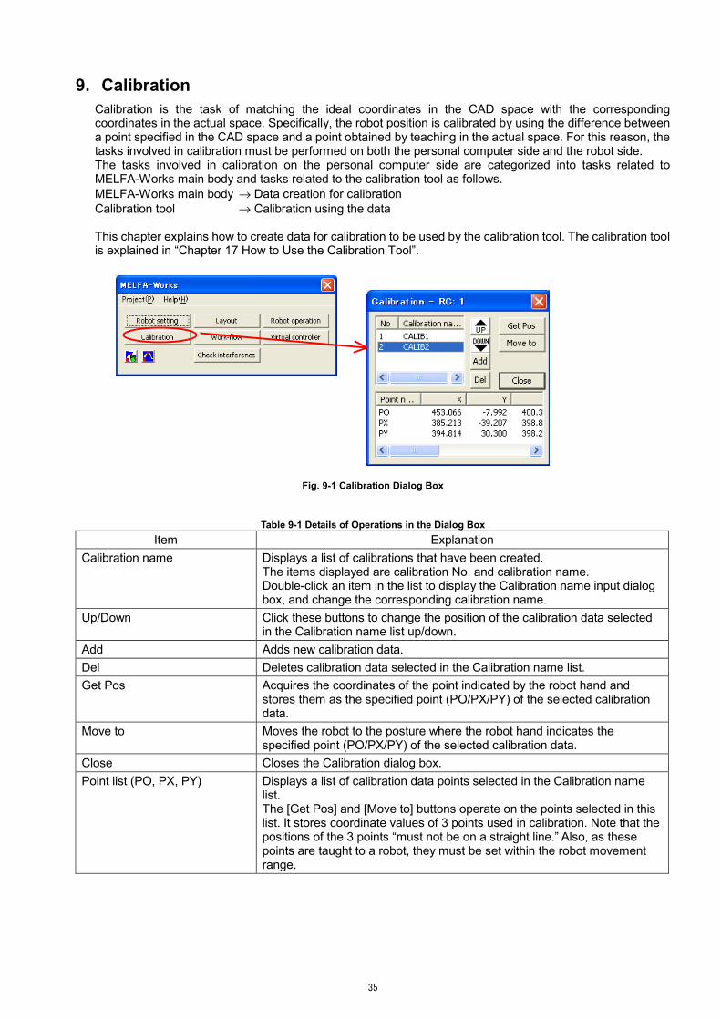
9. Calibration Calibration is the task of matching the ideal coordinates in the CAD space with the corresponding coordinates in the actual space. Specifically, the robot position is calibrated by using the difference between a point specified in the CAD space and a point obtained by teaching in the actual space. For this reason, the tasks involved in calibration must be performed on both the personal computer side and the robot side. The tasks involved in calibration on the personal computer side are categorized into tasks related to MELFA-Works main body and tasks related to the calibration tool as follows. MELFA-Works main body → Data creation for calibration Calibration tool → Calibration using the data
This chapter explains how to create data for calibration to be used by the calibration tool. The calibration tool is explained in “Chapter 17 How to Use the Calibration Tool”.
Fig. 9-1 Calibration Dialog Box
Table 9-1 Details of Operations in the Dialog Box Item Explanation
Calibration name Displays a list of calibrations that have been created. The items displayed are calibration No. and calibration name. Double-click an item in the list to display the Calibration name input dialog box, and change the corresponding calibration name.
Up/Down Click these buttons to change the position of the calibration data selected in the Calibration name list up/down.
Add Adds new calibration data. Del Deletes calibration data selected in the Calibration name list. Get Pos Acquires the coordinates of the point indicated by the robot hand and
stores them as the specified point (PO/PX/PY) of the selected calibration data.
Move to Moves the robot to the posture where the robot hand indicates the specified point (PO/PX/PY) of the selected calibration data.
Close Closes the Calibration dialog box. Point list (PO, PX, PY) Displays a list of calibration data points selected in the Calibration name
list. The [Get Pos] and [Move to] buttons operate on the points selected in this list. It stores coordinate values of 3 points used in calibration. Note that the positions of the 3 points “must not be on a straight line.” Also, as these points are taught to a robot, they must be set within the robot movement range.

36
9.1. Calibration Data Creation Procedure Calibration data refers to a data set consisting of 3 points that satisfy the following conditions. They have clear position relationships with workpieces. They are not on a straight line. They can be taught.
MELFA-Works allows specifying multiple calibration data sets. For example, if several workpieces exist in the vicinity of a robot, calibration can be performed for each workpiece to achieve highly accurate operation.
Click the [Calibration] button in the Main window and open the Calibration dialog box. Click the [Add] button to add calibration data. Click the calibration from the Calibration name list. Move the robot to the calibration point (refer to “8.2 Movement to a Corner”). Select the coordinate data (PO, PX, PY) and click the [Get Pos] button to acquire the position.
Prepare 3 points used for calibration data creation in advance to improve the positioning accuracy by the robot. During the calibration, these 3 points are taught; be aware that characteristic points such as corners can be taught at higher accuracy. If 3 points cannot be prepared on a workpiece model, 3 points on a peripheral device such as a workpiece fixing base can also be used, as far as the position relations are clear.
Fig. 9-2 Specifying 3 Points on Workpiece Fig. 9-3 Specifying 3 Points on Workpiece Fixing Base
About calibration
In order to move the actual robot with high accuracy, the accuracy of calibration is important. “3 pointsthat are not on a straight line” are required for teaching during calibration. These 3 points shouldpreferably be located at some distance from each other, rather than very densely together, in order toimprove the accuracy.
CAUTION

37
9.2. To Perform Highly Accurate Calibration In order to perform highly accurate calibration, specify the layout of the robot and workpiece position relationship as accurately as possible. It is possible to correct deviance through calibration, but the smaller the difference between the status before and after calibration, the higher the accuracy. It is essential to create conditions that match the actual environment as closely as possible in the CAD software. To specify the layout of the robot and workpiece position relationship, it is convenient to use the layout function of MELFA-Works (refer to “Chapter 7 Layout”).
Fig. 9-4 Example of CAD Link Execution
Use the layout function of MELFA-Works to create conditions that match the actual environment as closely as possible.

38
10. Creation of Work Flow A work flow refers to a series of operations such as moving to point A, carrying out processing along path B and finally moving to point C. In MELFA-Works, such work flows are created and eventually converted to robot programs. Such robot programs contain position data as well as information for tracing along a path; they can be used as templates for programs used in actual systems. It is possible to add teaching data and path data to a work flow. This chapter explains how to create teaching data, path data and work flows. The different terms have the following meaning.
Teaching data Teaching data is loaded robot posture information. The posture information includes the position/direction at the robot’s mechanical interface section and structure flags, and is the same as the teaching data for the actual robot. The posture/path registration area is used (see “10.1 Creating Teaching Points”).
Path data Path data is a general term for edges on workpieces and other areas processed by a robot and various conditions such as speed and acceleration/deceleration required for processing. Processed areas are extracted from path data and converted to collective dot sequence data with direction. The posture/path registration area is used (see “10.2 Path Creation”).
Work flow A work flow is a sequence of work tasks created by combining teaching data and path data. A work flow can be converted to a robot program or into dot sequence data. In doing so, the work and work flow registration areas are used (see “10.4 Work Flow Creation”).
Fig. 10-1 Work-flow Dialog Box
Posture/path registration area
Work registration area
Work flow registration area

39
10.1. Creating Teaching Points Through the use of teaching points, it is possible to store robot postures and subsequently reproduce the postures. Postures stored here can be reflected in the final robot program output by specifying MOV or MVS as the movement method and registering them in work flows.
Fig. 10-2 Work-flow Dialog Box (Teaching Point Creation)
Operation procedure
Change the robot posture in the Robot operation dialog box. Click the [Get location] button in the Teaching tab to add the current posture to the list. Select unnecessary postures from the list and click the [Delete location] button. To check a posture, select it from the list and click the [Move to] button. Select a method of movement (MOV/MVS) and click the [Add to Flow] button to add the posture to the work flow. The work flow must be created in advance (see “10.4 Work Flow Creation”).
Table 10-1 Details of Operations in the Dialog Box
Item Explanation Teaching point list Names and coordinates of created teaching points are displayed in a list.
Double-click an item in the list to display the position data edit dialog box, in which it is possible to edit coordinate values.
UP/DOWN Move the position of the teaching point selected in the teaching point list up/down.
Get location Acquires the robot posture that is the target of operation. Delete location Deletes the teaching point selected in the teaching point list. Move to Moves the robot to the teaching point selected in the teaching point list. MOV/MVS Select MOV or MVS as the method to move to the teaching point selected in
the teaching point list. Add to Flow It is possible to add the teaching point selected in the teaching point list to the
flow.
Teaching point list
Work list Work flow

40
10.2. Path Creation
A path refers to a series of movements of a robot, for instance to trace a specific area on a workpiece (edge area) with a processing hand. Paths created here can be reflected in the final robot program output by registering them in work flows.
Fig. 10-3 Work-flow Dialog Box (Path Creation)
Operation procedure
Click the [Add] button in the Path tab to add a path to the list. Double-click the created path or select it and then click the [Edit] button to open the Processing setting dialog box and edit the information in detail. This is explained in more detail in the next chapter.
Select unnecessary paths from the list and click the [Del] button. Select a path and click the [Trial] button to check the robot movement. Select a path and calibration and then click the [Add to Flow] button to add them to the work flow. The
work flow must be created in advance (see “10.4 Work Flow Creation”).
Table 10-2 Details of Operations in the Dialog Box Item Explanation
Path list Displays a list of created paths. Double-click an item in the list to display the Processing setting dialog box, in which it is possible to make detailed settings for the path.
UP/DOWN Changes the order of the path list. Click these buttons to move the position of the path selected in the path list up/down.
Add Adds a new path to the path list. Click this button to add a new path to the path list for which no settings have been made. Click the [Edit] button or double-click the item in the path list to make detailed settings for the path.
Del Deletes a path. Click this button to delete the path selected in the path list.
Edit Edits detailed settings of a path. Click this button to edit detailed settings of the path selected in the path list.
Unite Unites multiple paths into a single path. Click this button to combine multiple paths selected in the path list to create a new path. Only information of edges and faces is combined for the created path; the path information of the top path in the list is used for other information.
Work list
Path list

41
Item Explanation Copy Copies a path.
Click this button to copy the path selected in the path list. Trial Tries out a created path.
Click this button to check whether or not there are any impossible postures along each of the created paths. At this point, the Robot operation dialog box should be displayed, so that you may observe the angle of each axis and other information during movement.
Calibration selection Click this button to select the calibration data to be used when correcting the path selected in the path list.
Add to Flow Adds a path to a flow. Click this button to add the path selected in the path list to the flow.
10.3. Processing Setting Dialog Box
Information required for processing is set using this dialog box. The table below explains the information required for processing in details.
Fig. 10-4 Processing Setting Dialog Box
Operation procedure Double-click the created path or select it and then click the [Edit] button in the Path tab to open the Processing setting dialog box and edit the detailed information. The details are explained in the next chapter.
Select unnecessary paths from the list and click the [Del] button. Select a path and click the [Trial] button to check robot movement. Select a path and calibration and then click the [Add to Flow] button to add them to the work flow.
Work flow list

42
Table 10-3 Details of Operations in the Dialog Box
Item Explanation Processing name Displays the name of the path selected in the Work-flow dialog box.
When adding a new processing, the default name is set; the path name can be modified by changing the information in this text box.
Edge list Displays segments constituting the path selected in the Path creation dialog box as a list. When the registered edge is double-clicked, it reverses.
UP DOWN
Change the order of the segment list. Click these buttons to move the position of the segment selected in the segment list up/down.
Add Adds a new segment to the segment list. Select a face on the window and click the [Add] button to add a new path. When a path is correctly added, a dot sequence is drawn as shown in the figure below. Since edges (segments) and faces (surfaces) of the workpiece clicked last are selected, click a face once and then click an edge related to the face and the [Add] button repeatedly, to add the edges quickly and efficiently. * The object of the processing is only workpiece(”***_Work.sldprt”).
→ → Click a face Click an edge Click [Add]
Repeat until done Coordinate system
Del Deletes a segment.
Click this button to delete the segment selected in the segment list.
Maximum speed(mm/s) Specify the maximum speed of the robot when it processes a segment. Specify the speed at which to trace an edge (mm/s).
Acceleration/deceleration time Specify the acceleration/deceleration time of the robot when it processes a segment.
X
Z
Y

43
Item Explanation Approach/Overrun distance Specify the approach and overrun distances of the robot when it processes a
segment. At the start and end of robot movement, the speed fluctuates due to acceleration/deceleration. In order to be able to process the specified edge at a constant speed, specify approach and overrun distances. Approach: It is possible to set an approach position at a point along an
extension of the specified edge, extending from the start position of the edge in the opposite direction of the traveling direction. Specify the distance of the approach section (mm).
Overrun: It is possible to set an overrun position at a point along an extension of the specified edge, extending from the end position of the edge in the traveling direction. Specify the distance of the overrun section (mm).
Fix posture Specify whether or not the posture should be fixed when the robot processes a segment. If the check box is enabled, the posture is fixed. If it is disabled, the posture is not fixed.
Reverse course Specify whether or not to reverse segment processing direction. If the check box is enabled, the course is reversed. If it is disabled, the course is not reversed.
Reverse Z Specify whether or not to reverse in the Z-axis direction of a dot sequence when the robot processes a segment. If the check box is enabled, the coordinate system is reversed in the Z-axis direction. If it is disabled, the coordinate system is not reversed. When a hand processing area traces an edge, it moves by matching the Z direction of Orig2 to the normal line direction and the X direction of Orig2 to the traveling direction. Thus, it is possible to determine absolutely whether or not to reverse in the Z-axis direction by the processing point ("Orig2") and the normal line direction on the face when creating a hand.
(Example 1) →
(Example 2) → Tool Offset Offsets a line in the tool coordinate system.
Enter a value directly into the text box or enter the amount of offset in the offset input dialog box displayed by clicking the button next to the text box. Tool Offset specifies the amount of deviation when the actual hand processing point deviates from the processing point (coordinate system ”Orig2”) on the hand model. The figure below shows an example where the Y component is corrected. It is possible to use Course Offset at the same time.
End position
Start position
Approach position Overrun position
Approach distance
Overrun distance
X
Y
CAD output result
Processing path after offset calculation

44
Item Explanation Course Offset Offsets the course of a line.
Enter a value directly into the text box or enter the amount of offset in the offset input dialog box displayed by clicking the button next to the text box. Specify the amount of offset in the coordinate system where the forward direction of the segment course is set as the +X-axis direction and the direction away from a face as the +Z-axis direction. For example, when tracing a curve, the Y component indicates the inward/outward rotation, the Z component indicates the amount of approach and the A component indicates the bank angle. The figure below shows an example where the Y component is corrected. The examples in the figures below show the standard conditions, conditions where the Z component is corrected, and conditions where the A component are corrected, respectively.
Standard condition Z component correction A component correction
Output signal Sets the signal condition. If the check box is disabled:
The signal status before processing is maintained as is. If the check box is enabled:
Turns the signal on according to the set conditions and off at completion. Head bit When outputting signals while the robot is processing a segment, it is possible
to specify the head bit of the output signal (decimal expression). Mask bit Specify the bits to be controlled for 16 bits from the head bit (hexadecimal
expression). Output value Specify a value to be output (decimal expression). The actual output consists
of the bits, starting from the head bit, for which the corresponding mask bits are turned on.
Beginning delay Allows specifying to turn a signal on after the specified time (in seconds) has elapsed since the beginning of movement. A negative value can be set here as well. In this case, the robot starts moving after the specified number of seconds has elapsed after the signal is output.
End delay Allows specifying to turn a signal on after the specified time (seconds) has elapsed since the end of movement. A negative value can be set here as well. In this case, the signal is turned off the specified number of seconds before the robot reaches the end point.
Each item set in this dialog box becomes valid for all edges displayed in the segment list.
X
X
Y X
Y
Y
CAD output result
Processing path after offset calculation
X
Y
Z

45
10.4. Work Flow Creation In the Work-flow creation dialog box, it is possible to create a work flow by combining already created teaching points and paths. A created work flow can be converted into a robot program used as a template for actual operational programs.
Fig. 10-5 Work-flow Dialog Box (Work Flow Creation)
Operation procedure Click the [Add] button to create a new work flow. Select the Teaching or Path tab to register teaching points and paths registered in each tab to the work flow.
Click the [Conv] button to create the following files from the work flow.
Table 10-4 List of Output Files MXT***.mxt Path data. A robot program loads this file to trace the specified processing
area. The file name is automatically generated based on the number of dot sequences output and similar.
MXT***.cal A copy of MXT***.mxt (original). CLB.prg A calibration program.
This program is transferred to a controller by the calibration tool. By performing teaching with the transferred program, correction values are calculated based on the teaching results.
CLB.cal A copy of CLB.prg (original). FLOW.prg A work flow converted into a robot program. A movement program is
automatically generated from the relevant path data. This program can be used as is, but the final program is typically created by adding instructions and similar to this program according to the environment employed by the customer.
Table 10-5 Details of Operations in the Dialog Box Item Explanation
Work flow list Displays a list of created work flows. The items displayed are work flow No. and work flow name. Double-click an item in the list to display the name change dialog box, in which you can change work flow names.
Work flow list
Use this area
Work list

46
Item Explanation UP/DOWN Change the order of the work flow list.
Click these buttons to move the position of the work flow selected in the work flow list up/down.
Add Adds a work flow. Click this button to create a new work flow.
Del Deletes a work flow. Click this button to delete the work flow selected in the work flow list.
Conv Converts a work flow into a robot program. Click this button to convert the work flow selected in the work flow list and create a robot program and/or a dot sequence data set (information based on which an actual robot can move).
Teaching point/path list Displays teaching points and paths constituting a work flow as a list. The items displayed are item number, instruction name of item, teaching point/path name and calibration name of teaching point/path.
UP/DOWN Change the order of the teaching point/path list. Click these buttons to move the position of the teaching point/path selected in the teaching point/path list up/down.
Del Deletes a teaching point/path. Click this button to delete the teaching point/path selected in the teaching point/path list.
Close Closes the Work-flow dialog box. Click this button to finish creating work flows and close the Work-flow dialog box.
What is dot sequence data?
Dot sequence data refers to a collection of points constituting an edge to be traced with theCAD software in the CAD link function. It is also called MXT-data, because the file extension isMXT.
Tips

47
11. Virtual Controller MELFA-Works allows starting a virtual robot controller supporting a positioned robot. Since this virtual controller simulates the actual robot controller almost exactly, it can be used just like an actual controller in almost all operations, such as program creation, parameter setting and monitoring, using RT ToolBox. Also, by connecting a virtual controller with the currently displayed robot, the movement of a robot program can be reproduced as is.
Fig. 11-1 Simulator Dialog Box
Click the [Virtual controller] button from the Main window to display the Simulator dialog box. In this dialog box, buttons and other controls that are not used frequently are hidden as advanced functions. Click the
button to expand the dialog box and display them as necessary.
Table 11-1 Function Classification of the Simulator Dialog Box Item Explanation
General-purpose functions
Functions corresponding to those performed on the operating panel of a robot controller, such as program selection, start and end, are arranged in this section.
Advanced functions
The following functions, which are not part of the general-purpose functions, are arranged here.
Control of virtual controller time axis Stopwatch that measures cycle times Recording function I/O ignore mode toggle switch (B Mode)
General-purpose functions
Advanced functions

48
Table 11-2 General-purpose Functions Item Description
Program Displays the currently selected robot program name. After selecting [Program] with the option radio button, it is possible to select other programs using the [Up] and [Down] buttons.
Line No. Displays the line being executed in the currently executed robot program. Ovrd Displays the current OVRD value. After selecting [Ovrd] with the option radio
button, the value can be changed in increments of 10% using the [Up] and [Down] buttons.
START Executes the currently selected robot program. RESET Resets an error or program.
When an error has occurred: The error is reset. When a robot program is paused: The execution is returned to the first line
of the program. CONNECT Connects/disconnects the communication between the virtual controller and
virtual robot. When connected: The posture information is acquired from the virtual
controller and the robot posture display is updated. When disconnected: Updating of the robot posture is stopped to allow
offline operation. STOP Pauses the currently executed program.
Press the [START] button to resume the program from the paused line. END Ends the currently executed program in 1 cycle (the next time the END
instruction is met). Press the [START] button to resume the program from the first line of the program.
Error Num Displays an error number. If an error occurs, the error number is displayed.
Table 11-3 Advanced Functions
Item Description Time Stop Stops using the virtual controller.
Unlike normal stopping, the controller is stopped at the current position as if the time is frozen, even if the robot is operating at a high speed. Click the button again to cancel the time stop and return to the normal operation.
Step If the robot controller is stopped by clicking the [Time Stop] button, clicking this button allows the time to pass for a single time step (minimum controllable time unit). Also, an interference check is executed automatically after one step.
Repeat Executes [Step] repeatedly. StopWatch(sec)
Start/Stop Measures the time within the virtual controller as well as the actual time. It is possible to estimate an approximate cycle time. This function measures the time from clicking the [Start] button until it is clicked again. The measurement result is displayed in the [R/C] and [Real] boxes. * The time within the virtual robot controller can be measured only during
executing a robot program. Movie
Start/Stop Saves robot movement and similar as moving images.
B Mode Select whether or not to operate a robot program in B mode. If the check box is enabled, a robot program is operated in B mode. B mode is a function that runs a robot program while ignoring signal inputs from external devices.
Table 11-4 Functions Assigned to Tool Tips
Item Description Cycle time measurement Displays the cycle time measurement section.
The cycle time measurement section is displayed at the bottom of the Simulator dialog box.
JOG panel Displays the JOG Panel window. The JOG Panel window for operating a robot is displayed.

49
Item Description Step Execute/Direct Execute Displays the Step Execute/Direct Execute dialog box, in which it is possible to
perform step execution/direction execution of a robot program. Task Slot Displays the Task Slot dialog box, in which it is possible to check/correct task
slots. I/O Simulator Displays the I/O Simulator dialog box, in which it is possible to perform I/O
simulation. 11.1. How to Execute Programs
Execute a program using the following procedure.
Click the [Virtual controller] button in the Main window to display the Simulation dialog box. Click the [POWER] button to launch the virtual controller. Use RT ToolBox as necessary to change parameters of the virtual controller. If any parameters are
changed, click the [POWER] button again to restart the virtual controller. Use RT ToolBox to transfer the robot program to the virtual controller. Click the [CONNECT] button to connect the virtual controller and the robot. Click the [START] button to execute the program.
11.2. Checking Robot Interference
Carry out an interference check using the following procedure.
Display the Check interference dialog box and set the targets of the interference check (see “Chapter 12 Interference Check).
Execute a robot program and monitor the movement. Click the [TimeStop] button before a critical operation to perform the interference check. Click either the [Step] or [Repeat] button to start analysis (interference check). When [Stop at interference] is enabled in the Check interference dialog box, the continuous analysis
is stopped immediately if an interference is detected during continuous analysis. To end the analysis, click the [TimeStart] button.
Fig. 11-2 Switching among Analysis Modes
How to check efficiently
Since the calculation burden involved in an interference check is very heavy, the robot operationslows down. Checking only operations that are suspected of interference improves efficiency.
Tips
[TimeStop] button : Shift to analysis mode
[Step] button : Single step analysis [Repeat] button : Executes continuous analysis. [TimeStart] button : Cancels analysis mode.
[Step] button : Cancels continuous analysis. [TimeStart] button : Cancels analysis mode.

50
11.3. Saving Simulation Moving Images It is possible to save the SolidWorks display area shown in the figure below as a moving image file. * If another window is displayed on top of this area, the window is also saved as a part of the moving
image. * The processing may slow down depending on the window size. In such cases, you can scale down the
window before using the function.
When the operation you want to save starts, click the Movie [Start] button. At this point, the button display changes to [Stop].
When the operation you want to save is completed, click the Movie [Stop] button. A dialog box for specifying the file to be saved appears; select a file name and save the file.
Area saved in amoving image file
Fig. 11-3 Saved Area
* The processing may slow down depending on the window size. In such cases, you can scale down the
window before using the function.
Fig. 11-4 Saving in Moving Image Files
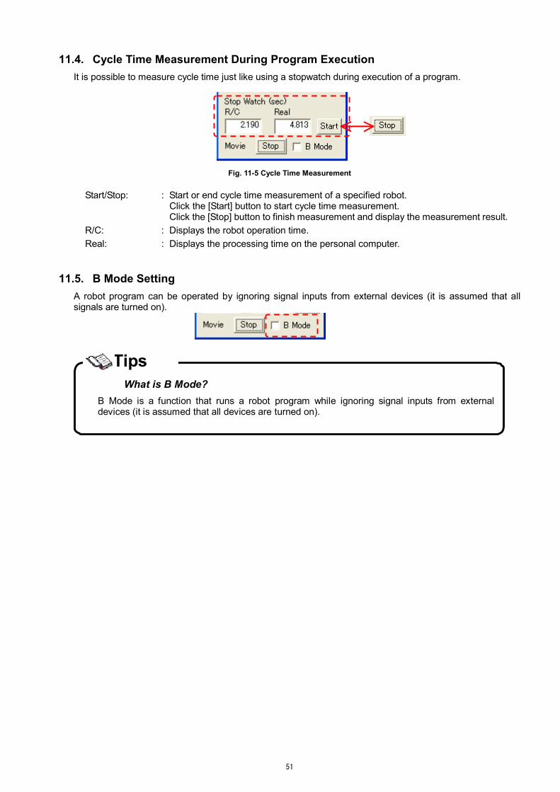
51
11.4. Cycle Time Measurement During Program Execution It is possible to measure cycle time just like using a stopwatch during execution of a program.
Fig. 11-5 Cycle Time Measurement
Start/Stop: : Start or end cycle time measurement of a specified robot.
Click the [Start] button to start cycle time measurement. Click the [Stop] button to finish measurement and display the measurement result.
R/C: : Displays the robot operation time. Real: : Displays the processing time on the personal computer.
11.5. B Mode Setting
A robot program can be operated by ignoring signal inputs from external devices (it is assumed that all signals are turned on).
What is B Mode?
B Mode is a function that runs a robot program while ignoring signal inputs from externaldevices (it is assumed that all devices are turned on).
Tips

52
12. Interference Check MELFA-Works is able to check for interference among parts that are registered into 2 groups in a round-robin system. In addition to simply checking the current interference status, it is also able to link with the continuous analysis mode of the virtual controller, such that a program can be stopped if interference is detected (refer to ”11.2 Checking Robot Interference” for details). Although the level varies depending on how powerful the personal computer executing the simulation is, the larger the number of registered parts, the longer the check time. Register the minimum required parts to use this function.
Fig. 12-1 Interference Check Dialog Box
Table 12-1 Details of Operations in the Dialog Box Item Explanation
Target parts list While one of these lists is selected, click a part in SolidWorks to add the part name to the list. If the part has already been added to a list, it is deleted from the list. In a round-robin system, interference is only checked between parts included in the upper and lower lists; interference is not checked within the same list. If interference is detected, the lists flash in red.
Check Now Checks the current interference status. It is possible to check the interference status at the time of clicking the [Check Now] button.
History Displays the Interference history dialog box. The Interference history dialog box shows a history of which part interfered with which part, along with the times when the interference occurred.
Stop at interference If interference is detected, it is possible to stop the program immediately so that the user may check the interference status of the simulation. If this check box is enabled, the program is stopped when interference is detected. If the box is disabled, the program is not stopped.
Clear Clears the interference history. Save Saves the interference history in a file.

53
13. Task Slots Use the Task Slot dialog box to set multiple programs at the same time, for instance when using multitasking.
Fig. 13-1 Task Slots
There are the following 2 correction buttons. [Individual correction]: : Make correction for the selected task slot. [Batch correction]: : Make correction for task slots 1 to 8 and user base program settings at the
same time. 13.1. Individual Correction of Task Slots
Make correction for the selected task slot. Select a task slot for which you want to make correction from the list of task slots and click the [Individual correction] button (refer to Fig. 13-1 Task Slots).
Information of the selected slot is displayed. Specify the [Program file], [Mode], [Conditions] and [Priority], and then click the [Write] button.
Fig. 13-2 Individual Correction

54
13.2. Batch Correction of Task Slots
Make correction of task slots 1 to 8 and user base program settings at the same time. Select the connected robot in the combo box in the upper part of the dialog box and click the [Batch correction] button.
Only information ofthe task slots forwhich the check boxis enabled is set inthe controller.
Specify a robot program file on the personal computer.
Enter the programname directly or clickthe button to openthe Open dialog box.
Fig. 13-3 Batch Correction
Enable the check boxes of task slots to be corrected. Specify a program to be set to each task slot. Modify the [Mode], [Condition] and [Priority] as required. Click the [OK] button. When setting is completed, the corresponding virtual robot controller is
restarted.

55
14. Input/Output Signal Simulation The I/O simulator allows monitoring a robot’s input/output signals and simulating these signals.
Monitoring list
Fig. 14-1 I/O Simulator
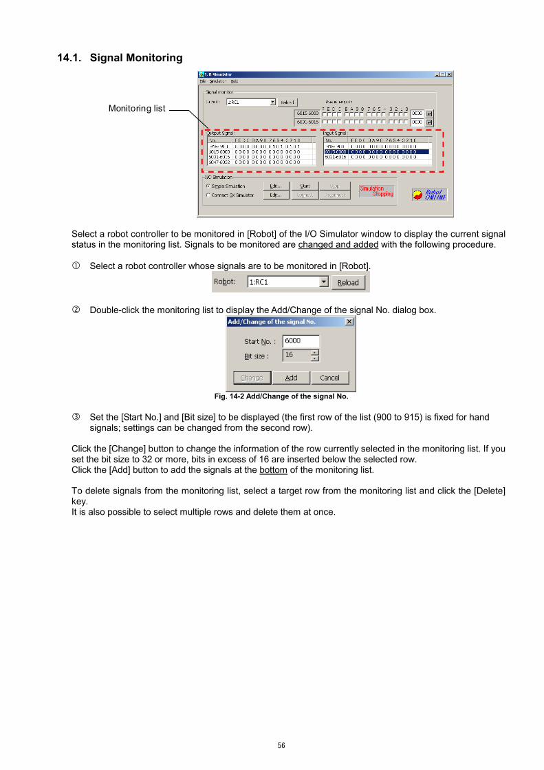
56
14.1. Signal Monitoring
Monitoring list
Select a robot controller to be monitored in [Robot] of the I/O Simulator window to display the current signal status in the monitoring list. Signals to be monitored are changed and added with the following procedure. Select a robot controller whose signals are to be monitored in [Robot].
Double-click the monitoring list to display the Add/Change of the signal No. dialog box.
Fig. 14-2 Add/Change of the signal No.
Set the [Start No.] and [Bit size] to be displayed (the first row of the list (900 to 915) is fixed for hand
signals; settings can be changed from the second row).
Click the [Change] button to change the information of the row currently selected in the monitoring list. If you set the bit size to 32 or more, bits in excess of 16 are inserted below the selected row. Click the [Add] button to add the signals at the bottom of the monitoring list. To delete signals from the monitoring list, select a target row from the monitoring list and click the [Delete] key. It is also possible to select multiple rows and delete them at once.

57
14.2. Manual Signal Inputs Input signals to a robot controller can be turned on/off. Input signals are specified manually according to the following procedure.
Inputting 1 bit at a time Click a row in the controller’s input signal list (the signal numbers of the selected row and the next row
are displayed in the pseudo-input area). Enable/disable a check box to turn the corresponding controller input signal on/off (the status is
updated immediately after the click).
Inputting 16 bits at once Enter the hexadecimal value corresponding to the desired signal status in the input column and click
the button. Pseudo-input area
Specify on/off status by entering a hexadecimal value in the signal status input column and click the
button.
Display signal numbersof the clicked row
Fig. 14-3 Pseudo-input of Input Signals

58
14.3. Simulation Definition Settings It is possible to simulate input/output signals. Define signals according to the following procedure in order to perform simulation. Click the [Edit] button in the [Simple Simulation] area of the I/O Simulator window to set the definition.
The definition of I/O simulation window appears.
Fig. 14-4 Definition of I/O Simulation
Add a signal operation definition.
Click the [Add] button at the bottom of the window to display the Setting of the behavior of the signal dialog box. Set the simulation conditions and signals output when the conditions are met in this dialog box.
If you enable this box, a second set of conditions can be set.
If you enable this box, the signal output conditions canbe set only once after simple simulation is started.
Specify a controller number in the [Robot] input field. Click the […] button to display the Select the Robot. dialog box and select the appropriate controller number from the dialog box.
Fig. 14-5 Setting of the Behavior of the Signal
To change an already set definition, select it in the list and click the [Edit] button. Alternatively, double-click it in the list to achieve the same effect.

59
The signal definition is added to the list.
“(bin)” in the [Status] column indicates that thesignal status is expressed as a binary number.
Disable a check box to invalidate the corresponding definition during I/O simulation.
Fig. 14-6 Defined Simulation Conditions
It is judged whether the set definitions are met or not in order from the top of the list. However, the initial execution definition is only output once when simple simulation is started (before
normal simulation).
Button operations Add : Adds a simulation definition.
Select a row and click the [Add] button to use the setting values of the selected row as the default values for the new definition.
Edit : Changes a simulation definition. Select a row and click the [Edit] button.
Delete : Deletes the definition of the selected row. It is also allowed to select multiple rows to delete them at once.
: Move the definition of the selected row up or down. It is also allowed to select multiple rows to move them at once.
Load : Loads simulation definitions from MELFA-Works project files. Please be careful when performing this operation; current definitions displayed in the list will be cleared.
Save : Saves the current simulation definitions in project files of MELFA-Works.
Be sure to stop the simulation before changing definitions. During simulation, it is possible to check definitions, but it is not possible to add, change, delete orload definitions. Stop the simulation before performing these operations.
CAUTION

60
14.4. Executing Signal Simulation To perform signal simulation, select the [Simple Simulation] radio button and click the [Start] button. Simulation is executed using the set definitions.
Fig. 14-7 Buttons Related to I/O Simulation
Simulation status is displayed.
Display while simulation execution:
Display when simulation is stopped:
If the [Start] button is clicked when no definition is set, a dialog box for selecting a definition setting method appears. Select a setting method and click [OK]. Definitions are loaded using the selected method and simulation is started.
Fig. 14-8 New Definition Dialog Box
Starting simple simulation
Simple simulation is started when monitoring with MELFA-Works is started while I/O simulator is displayed as well.
Tips

61
14.5. Settings of Connection with GX Simulator It is possible to connect with GX Simulator to simulate signal exchanges between the virtual controller in MELFA-Works and a PLC (represented by GX Simulator).
GX Simulator versions
Currently, only GX Simulator Version 7 is supported.
CAUTION
To connect with GX Simulator, define GX Simulator devices and assign the signal numbers of the robot controller according to the following procedure. Click the [Edit] button after enabling the [Connect GX Simulator] radio button to set definitions. The
Communication Setting with GX Simulator window appears.
Fig. 14-9 Communication Setting with GX Simulator Window
Select the [Series] and [Type] of a device set in GX Simulator.
Add an I/O wiring definition with GX Simulator.
Click the [Edit] button at the bottom of the definition list on the side to be defined to display the setting dialog box.
To change an already set definition, select it in either of the lists and click the [Edit] button. Alternatively, double-click it in the list to achieve the same effect.

62
Set the signal numbers of the robot controller and the PLC device. Select the signal types and the PLC device as well.
Specify a controller number in the[Robot] input field. Click the […] button to display theSelect the Robot. dialog box and select the appropriate controllernumber from the dialog box.
Fig. 14-10 Signal Connection Settings
Defined signals are added to the list as shown in the figure below.
Fig. 14-11 Connection of Defined Signals
Button operations
Edit : Edits a definition of connection with GX Simulator. Delete : Deletes the definition in the selected row.
It is also allowed to select multiple rows to delete them at once.
: Move the definition of the selected row up or down. It is also allowed to select multiple rows to move them at once.
Load : Loads definitions of connection with GX Simulator from MELFA-Works project files. Please be careful when performing this operation; current definitions displayed in the list will be cleared.
Save : Save the current definitions of connection with GX Simulator in project files of MELFA-Works.

63
14.6. Connecting with GX Simulator To connect with GX Simulator, select the [Connect GX Simulator] radio button and click the [Connect] button. Connection is established with the set definitions.
Fig. 14-12 Connect GX Simulator
Simulation status is displayed.
Display while connected with GX Simulator:
Display when simulation is stopped:
If the [Connect] button is clicked when no definition is set, a dialog box for selecting a definition setting method appears. Select a setting method and click [OK]. Definitions are loaded using the selected method and connection is established.
Fig. 14-13 New definition Dialog Box
Precautions when connecting to GX Simulator When receiving GX Simulator pulse outputs with a robot controller or receiving pulse outputs fromthe robot controller with GX Simulator, be sure to have a pulse output time of 300 ms or more as aguideline. This guideline varies depending on the performance and usage conditions of your personal computer as well.
CAUTION

64
15. Step Execute/Direct Execute Dialog Box 15.1. Step Execution
It is possible to perform step execution of a specified program. Select the program to be started in the Simulator dialog box and open the Step Execute/Direct Execute dialog box from the toolbar. Next, click the [Reference (B)] button and select the program currently being executed from the robot program files on the personal computer; the preparation is now completed.
Fig. 15-1 Step Execution
Click the [Reference (B)] button to select a program on the personal computer. The contents of the program are displayed in the Step execution tab.
(1) Line cursor color Green : Indicates the currently executed line. Yellow : Indicates lines set as break points
(2) Button operations
Step feed : Executes a specified program step by step. Execution : Runs a robot program from the current line continuously until it
encounters a break point. If no break point is set, the program is run until END.
Stop : Stops the program being executed. The program is stopped immediately, even during the execution of a
moving command. Set Breakpoint : Sets points where a program is stopped.
When the [Execution] button is clicked, the robot program stops at a line where a break point is set.
Up to 8 break points can be set at the same time. Release Breakpoint : Cancels break points already set.
Line cursor

65
15.2. Direct Execution It is possible to execute MELFA-BASIC commands directly using instructions and position data specified for the program in question. Select a program to be started in the Simulator dialog box and open the Step Execute/Direct Execute dialog box from the toolbar. Next, click the Direct execution tab.
Fig. 15-2 Direct Execution
(1) Operations in the dialog box [Reference (B)] button : Select a program on the personal computer.
[Reload] button : Click this button after editing a program file to reload the program with
the same file name as the currently loaded program.
[Command] field : Enter instructions to be executed directly.
[Execute] button : Execute an instruction entered in the [Command] input field. Executed instructions are added to the history list.
[History] list : Displays the history of directly executed instructions. Select an
instruction from the [History] list and click the [Execute] button to execute the instruction.
[Clear] button : Clears the history of directly executed instructions.
[Move To] button : Executes robot move instructions using position data in the specified
program. When you click the [Move To] button, the Moving command dialog box appears.

66
[Target Pos.] list : Double-click a position variable name among the program position data displayed in the list or select it and click the [Select] button to display the current value in the [Position] section. Click it to move the robot with the specified movement.
[Joint (J)] interpolation button [Cartesian (L)] interpolation button
: Click these buttons to move the robot to the posture displayed in the [Position] section using the specified movement. It is also possible to change the value of each element in the [Position] section to move the robot.
Be sure to specify a program when performing direct execution. A robot program must be specified when performing direct execution.
CAUTION
15.3. Measurement of Cycle Time
It is possible to measure the cycle time of a particular line of a specified program. After selecting a program to be started in the Simulator dialog box, open the Step Execute/Direct Execute dialog box from the toolbar. Then click the Measurement of cycle time tab.
Fig. 15-3 Measurement of Cycle Time
Click the [Reference (B)] button and select a program on the personal computer. The contents of the program are displayed in the Measurement of cycle time tab.
(1) Line cursor color Green : Indicates the line being executed Yellow : Indicates a point in the program where cycle time is measured (Mark ON).
(2) Button operations
Select all : Specify all lines of a program to be measured (all lines are displayed in yellow).
Line cursor(line being executed)
Line cursor(target line of measurement)
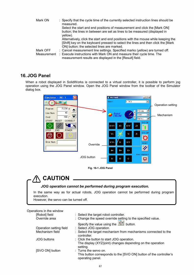
67
Mark ON : Specify that the cycle time of the currently selected instruction lines should be measured.
Select the start and end positions of measurement and click the [Mark ON] button; the lines in between are set as lines to be measured (displayed in yellow).
Alternatively, click the start and end positions with the mouse while keeping the [Shift] key on the keyboard pressed to select the lines and then click the [Mark ON] button; the selected lines are marked.
Mark OFF : Cancel measurement line settings. Specified marks (yellow) are turned off. Measurement : Execute instructions with Mark ON and measure their cycle time. The
measurement results are displayed in the [Result] field.
16. JOG Panel When a robot displayed in SolidWorks is connected to a virtual controller, it is possible to perform jog operation using the JOG Panel window. Open the JOG Panel window from the toolbar of the Simulator dialog box.
Fig. 16-1 JOG Panel
JOG operation cannot be performed during program execution. In the same way as for actual robots, JOG operation cannot be performed during programexecution. However, the servo can be turned off.
CAUTION
Operations in the window [Robot] field : Select the target robot controller. Override area : Change the speed override setting to the specified value.
Specify the value using the button. Operation setting field : Select JOG operation. Mechanism field : Select the target mechanism from mechanisms connected to the
controller. JOG buttons : Click the button to start JOG operation.
The display (XYZ/joint) changes depending on the operation setting.
[SVO ON] button : Turns the servo on. This button corresponds to the [SVO ON] button of the controller’s
operating panel.
Operation setting
Mechanism
JOG button
Override

68
[SVO OFF] button : Turns the servo off. This button corresponds to the [SVO OFF] button of the controller’s
operating panel. [RESET] button : Reset errors and programs.
This button corresponds to the [RESET] button of the controller’s operating panel.
[Hand alignment] button : Aligns hands. * The hand alignment function moves the A, B and C components
of the current position to the closest values in 90-degree unit.

69
17. How to Use the Calibration Tool Calibration refers to correcting deviation between the system configured in the CAD software and the actual system. These tasks are performed using the calibration tool, which is not included in MELFA-Works. The flow of tasks involved in calibration is as follows.
Specify an MXT file (*.MXT) output from MELFA-Works and load the corresponding dot sequence data. ↓
Transfer a calibration program for positional calibration to the robot controller. ↓
Teach the position variables of the calibration program to the robot. ↓
Load the calibration program into the tool. ↓
Correct the positions of the dot sequence data based on the loaded calibration program. ↓
Transfer a program for distortion calibration to the robot controller. ↓
Teach the robot such that it is moved to the correct position in accordance with the dot sequence.
↓ Load the program for distortion calibration to the tool.
↓ Calibrate the distortion of the dot sequence data based on the loaded
program for distortion calibration. ↓
Transfer the calibrated dot sequence data to the robot controller. ↓
Create a program that uses the dot sequence data on the robot.
Positional calibration
Distortion calibration
The calibration methods can largely be divided into “positional calibration” and “distortion calibration,” and they have the following features.
Item Explanation
Positional calibration
Calibrate the layout of the entire dot sequence data set. With this method, it is possible to correct deviations due to system assembly errors such as deviations between specified and actual robot and work station positions. Based on position deviations between 3 points specified in the CAD software and the corresponding actual points, the parallel and rotational component deviation in each coordinate system is calculated, and the entire dot sequence is calibrated accordingly.
Distortion calibration
Calibrate the specified part of the dot sequence data set. With this method, it is possible to correct deviations due to distortion of the workpiece itself and hand mounting errors. Specify the start and end of a part of the dot sequence data set for which position deviations should be calculated. Then teach several deviating points to the robot in order to correct the points in the specified sequence.
17.1. Starting When the calibration tool is installed correctly, it can be started from the [Start] menu.
Fig. 17-1 Starting the Calibration Tool

70
17.2. Explanation of the Calibration Tool Window The screenshot below shows the main window of calibration tool. This window is mainly used to check dot sequence data.
Table 17-1 Operations in the Calibration Tool Window
Item Explanation Controller Select the target robot controller to be used for operation. The combo box lists
controllers that are registered by the communication server and currently communicating.
Rotation of Axis Change the rotation angles of the coordinate axes in the dot sequence data display area by entering values directly or clicking the up/down button for each axis. It is also possible to change the angle by operating the mouse while clicking the Wheel button.
Movement of Viewpoint
Change the amount of parallel movement of the viewpoint in the dot sequence data display area by entering values directly or clicking the up/down buttons for each axis. It is also possible to change the amount by keeping the [Ctrl] key pressed and clicking the Wheel button of the mouse.
Zoom Set the zoom scale of the dot sequence data display area by entering a value directly or clicking the scale up/down button. It is also possible to change the zoom scale by clicking the Wheel button, or keeping the [Shift] key pressed and then clicking the Wheel button.
Point Location Display
Displays the specified sequence of points in red.
Dot sequence data display area
Displays the loaded dot sequence data.
17.3. Open MXT file
Select [Open MXT File] in the [File] menu or click the [Open File] button in the upper part of the window to specify an MXT file (*.mxt) output from MELFA-Works and load the dot sequence data. MXT files contain data generated when creating work flows (refer to “10.4 Work Flow Creation).
Combo box for selecting the target controller
Dot sequence datadisplay area

71
17.4. Executing Calibration After opening MXT file is completed, select [Position and Distortion Calibration] from the [Calibration] menu to display the Position and Distortion Calibration dialog box. Calibration can be carried out by performing operations in the order displayed in the dialog box.
Fig. 17-2 Position and Distortion Calibration Dialog Box
Table 17-2 Operations in the Position and Distortion Calibration Dialog Box
No. Calibration method Item Explanation
1 [Transfer Calibration Program] button
Transfers the calibration program to the selected robot controller. The program transferred here is the calibration program (CLB.prg), which is stored in the same folder as the loaded dot sequence data set.
2 [Teaching] (display only) After transferring the calibration program, use a teaching box or similar to perform teaching. See the detailed instruction procedure in Chapter 17.5.
3 [Read Calibration Program] button
Reads the calibration program (CLB.prg) from the robot controller after teaching.
4
Positional calibration
[Calibrate MXT Data] button
Calibrates positions of dot sequence data. Use a calibration program (CLB.prg) uploaded from the robot controller to calibrate a dot sequence data set. When the positional calibration is finished, the MXT file is overwritten as well.
5 [Write Calibration Program to RC] button
Generates a distortion calibration program (with the name CL (dot sequence number).prg) and transfers it to the robot controller.
6 [Teaching] (display only) After transferring the distortion calibration program, use a teaching box and similar to perform teaching. See the detailed instruction procedure in Chapter 17.6.
7 [Read Calibration Program from RC] button
Reads the distortion calibration program (CL (dot sequence number).prg) from the robot controller after teaching.
8
Distortion calibration
[Execute Calibration] button
Calibrates distortion of dot sequence data. Use a distortion calibration program (CL (dot sequence number).prg) uploaded from the robot controller to calibrate positions of the dot sequence data set. When the positional calibration is finished, the MXT file is overwritten as well.
9 [Undo Calibration] button Click the button to return the dot sequence data set to the initial status before calibration.
10
[Only Remake] button Reconfigures a dot sequence data set with the current settings without performing positional or distortion calibration. Use this function to test a dot sequence data before calibration to the robot or MELFA-Works.

72
17.5. How to teach the positional calibration program (CLB.prg) Select [Transfer Calibration Program] button on “Position and Distortion Calibration” window, the program named “CLB.prg” is transfered to the controller. This program is contained the positions for positional calibration which is set “Calibration” window of MELFA-Works. Register the correction position in the program for positional calibration as the following procedures. 1. Using the teaching box (T/B) which is connected to the controller, set “CLB.prg” program to edit mode. 2. Move the robot to each positions in this program (P**_O, P**_X, P**_Y(Each [**]is calibration data
number in MELFA-Works)). At this time, be carefull to avoid collision to peripherals. 3. If the positions which is moved and which is set on MELFA-Works are shifted, move the robot to the
position which is correspons on an actual system and teach again. 4. Please operate the above-mentioned by all the registered position data.
P01_O
before calibration
P01_O
after calibration
P01_Y
before calibration
P01_Y
after calibration
P01_X
before calibration
P01_X
after calibration
17.6. How to teach the distortion calibration program(CL(dot sequence number).prg) Select [Write Calibration Program to RC] button on “Position and Distortion Calibration” window, the program named “CL(dot sequence number)” is registered in the controller. This program is contained all dot sequence positions. Register the correction position in the program for distortion calibration as the following procedures. 1. Using the teaching box (T/B) which is connected to the controller, set “CL(dot sequence number)”
program to edit mode. 2. Move the robot to each positions in this program, check the position set on MELFA-Works whether shift.
At this time, move the robot noting no collision to peripherals. 3. If there is shift between moved position and a position set on MELFA-Works, “ ’0 “ is added to move
operation of beginning the gap and gap end position, and the position which shifts most is taught as shown in the figure below.
125 MOV P122 ’0
126 MOV P123
127 MOV P124
128 MOV P125
129 MOV P126
130 MOV P127
131 MOV P128 ’0
“ ’0 “ is added
to beginning the gap
“ ’0 “ is added
to the gap end
the position which
shifts most is taught
Dot sequence output
by MELFA-Works
Reteached dot sequence

73
17.7. Transferring Dot Sequence Data to Robot Controller When all calibration is finished, transfer the dot sequence data to the controller. Select [MXT Transfer PC − RC] from the [MXT File Management] menu to display the Transfer Confirmation of MXT File dialog box.
Fig. 17-3 Transfer Confirmation of MXT File Dialog Box
Click the [OK] button in this dialog box to transfer a dot sequence data set for which calibration has been completed to a robot controller. Also, by enabling the [The MXT confirmation program is transmitted] check box, it is possible to create a program (with the name 0101.prg) for confirming the robot movement and transfer it as well. Using a program for movement confirmation will make the subsequent creation of robot programs easier.
Check movement carefully. MXT instructions are used in movement confirmation programs (refer to Chapter 18 for the details). When using MXT instructions, the normal robot movement instructions are not used. Instead, the robot moves via commands from external sources (files or communication); it is thus not possible to control the speed by the override specification from a robot controller. In order to avoid dangerous situations, pay attention to the following points and check the robot movement carefully.
Be prepared to stop the robot anytime. Create dot sequence data with lower speed. Start from a status without any workpiece.
CAUTION

74
17.8. Managing Dot Sequence Data in Robot Controller The amount of dot sequence data that can be transferred to a robot controller is limited; use the MXT File Control in Robot Controller dialog box to delete unnecessary dot sequence data within a controller. Select [MXT file Management in RC] from the [MXT File Management] menu to display the MXT File Control in Robot Controller dialog box.
Fig. 17-4 MXT File Control in Robot Controller Dialog Box
Table 17-3 Operations in the MXT File Control in Robot Controller Dialog Box
No. Item Explanation 1 Dot sequence data list Displays a list of dot sequence data existing in a robot controller. 2 [RC → PC Reading]
button Click this button to upload the dot sequence data set in a robot controller and save it in a specified folder on the personal computer.
3 [List Renew] button Click this button to browse through the dot sequence data set in a robot controller and refresh the contents of the dot sequence data list.
4 [Delete] button Click this button to delete dot sequence data selected from the dot sequence data list from the robot controller.
5 [Close] button Click this button to finish MXT file management and close the dialog box.
Dot sequence data list

75
17.9. Movement Setting Change If the operation property is changed from initial state, this screen is used. Select [MXT Parameter Setting] from the [Calibration] menu to display Movement Setting Change screen.
When this screen is shown, it displays the current state. Set only the changed item, and click the [OK]
button. The state of the output signal changed on the screen in Chapter 17.10 is overwritten.

76
17.10. Editing Output Signal Status Select [I/O Setting] from the [Calibration] menu to display the I/O Output Setting dialog box. When outputting dot sequence data with MELFA-Works, the output signal settings are typically made for entire data sets at a time. This dialog box allows editing the status of individual output signals for each point; i.e., it allows the user to control I/O outputs in a detailed manner.
Fig. 17-5 I/O Output Setting Dialog Box
Table 17-4 Operations in the I/O Output Setting Dialog Box
No. Item Explanation 1 Signal output status list The output signal status list displays the states of the output signals of all
points. Select a point you want to modify from this list and set the output value in the corresponding text box.
2 [Head Signal Setting Value] field
Specify the head bit to be output (decimal expression).
3 [Mask Setting Value] field Specify up to 16 bits that are permitted to be output, starting from the head bit (hexadecimal expression).
4 [Value Setting Value] field Specify the value to be output, starting from the head bit (decimal expression). Only bits for which the corresponding mask bits are turned on are actually output.
5 [Setting] button Sets the I/O output settings that have been made in this dialog box. 6 [Delete] button Deletes I/O output settings that have been made. 7 [Cancel] button Does not set any I/O outputs; instead, closes the dialog box. 8 [OK] button Sets I/O outputs and closes the dialog box.
17.11. Change error tolerance when calibration
When dot sequence is reconstructed with the distortion correction etc., the error margin is caused in the process of the calculation. This screen is used to change the value (default value is 0.01mm).
Select [Various Setting] from the [Setting] menu to display Various Settings screen.
Signal output status list
[Head Signal Setting Value] field
[Mask Setting Value] field
[Value Setting Value] field

77
If the value is reduced, the accuracy at the distortion calibration etc. goes up. But the distance of dot sequence which can be corrected shortens.
Use default vaule if there is no probrem for accuracy or the distance of dot sequence.

78
18. CAD Link Programming So far it has been finished to create dot sequence data, perform calibration and transfer programs for test operations. This chapter explains how to construct an actual system using created data. The CAD link function supports only the MELFA-BASIC language.
The following files are generated in the process of using the CAD link function.
Table 18-1 Files Output by the CAD Link Function
No File name Purpose/generation method 1 FLOW.prg “Work program”
This file contains a program converted from a work flow. Copy and use it as a template for your own programs.
2 O1O1.prg “Movement confirmation program” This file contains sample programs for actually moving a robot using dot sequence data. * The file name is generated automatically according to the naming
rule.
3 MXT**_**.MXT “Dot sequence data (MXT data)” set This file contains dot sequence data describing robot movement along a workpiece. Downloading this file to a robot controller allows a robot to smoothly trace along the edge of a workpiece. This file is created by MELFA-Works and calibrated by the calibration tool. * The file name is generated automatically. After calibration is
completed, change the name as necessary and use the file.
4 CLB.prg ”Calibration program” This file contains a robot program used in calibration. Executing this program allows teaching calibration points and calculating calibration values based on the results of teaching. This program is created by MELFA-Works and downloaded/uploaded by the calibration tool to/from a robot. The calibration tool uses the calibration program in the current folder as the source of dot sequence data. * The file name is fixed.
5 MXT**_**.cal “Dot sequence data before calibration” This file contains dot sequence data before calibration. * The file name is the same as for the dot sequence data set above,
but the extension is "*.cal."
6 CLB. cal “Calibration program before teaching” This file contains a calibration program before teaching. * The file name is fixed.

79
18.1. Verifying Movement Confirmation Program The movement confirmation program is structured as follows.
10 'MXT Sample Program (MXT01_01.MXT)
Comment line
20 TOOL (+0.00,+0.00,+231.00,+0.00,+0.00,+0.00) Set installed tool data. The tool data is calculated from the hand used when dot sequence data is output from MELFA-Works and set as the default value. This is required when creating an operational program as well.
30 CLOSE #1 Close file #1 before loading a dot sequence data set. If the file is left open after the previous processing, an error occurs in the OPEN instruction in line 40. For this reason, it is typical practice to include a CLOSE instruction before the OPEN instruction in order to prevent unnecessary errors.
40 OPEN "MXT:MXT01_01.MXT" AS #1 Open the dot sequence file as file #1.
50 MOV P_MXT Move to the beginning of the currently opened dot sequence data set. At the MXT instruction on line 60, the robot moves according to the dot sequence data set; an error may occur if the current position and the head position are different. For this reason, the robot is moved to the position indicated by the first element in the dot sequence data set in advance.
60 MXT 1,0 Move the robot according to dot sequence data of file #1. A detailed explanation of using the MXT instruction is found in “18.2 MXT Instruction (Move According to External Instruction).”
70 CLOSE #1 Close file #1.
80 HLT Stop the program.
90 END End of the program.
* The speed with which the MXT instruction is executed cannot be controlled by the override specification of a controller; exercise caution when checking movement.
As can be seen with the example program for movement confirmation, a program is created in the following sequence to move a robot on dot sequence.
(1) Set a tool. (2) Open dot sequence data. (3) Move to the beginning of the dot sequence data set. (4) Move through the dot sequence data set using the MXT instruction.
This sequence is the same even when there are multiple dot sequence data sets to be traced.

80
18.2. MXT Instruction (Move According to External Instruction) With the MXT instruction, data can be acquired not only from a file but also via Ethernet communication. In this section, it is explained how to acquire data from a file. [Function] Move a robot directly by acquiring absolute position data from a file in each control sample interval. The file is specified by the OPEN instruction. [Format]
MXT <file number>, <instructed position data type>[, <filter time constant>] [Terminology] <File number> Specify a number in the range from 1 to 8; this value must match a file
number assigned with the OPEN command. If the file specified to be loaded has not been opened with the OPEN command, an error occurs and a robot does not move.
<Instructed position data type> Specify the type of position data commanded from the personal computer. Either XYZ or joint coordinate position data can be specified.
0: XYZ coordinate data 1: Joint coordinate data
<Filter time constant> Specify a filter time constant (msec). If 0 is specified, no filtering is applied (0 is set by default if the specification is omitted). Apply filtering to position data to create dampened instruction values and output to the servo.
<File name> Specify the name of the position data file loaded with the MXT instruction.
[Example]
10 OPEN "MXT:SAMPLE.MXT" AS #1 ' Open the SAMPLE.MXT file. 20 MOV P1 ' Move to P1. 30 MXT 1,0 ' Move according to the real-time external control. 40 CLOSE #1 ' Close the file. 50 HLT
[Explanation]
By executing the MXT instruction, it is possible to acquire position commands for movement control from the MXT file (format is explained later) specified by an OPEN instruction.
In each movement control sample interval (currently, approximately 7.1 msec), one position command is acquired and the robot is moved accordingly.
Operation of the MXT instruction (1) When this instruction is executed with the controller, data is loaded sequentially from the
MXT file and the robot moves to the specified position. (2) When all data in the MXT file is loaded, the MXT instruction is completed. (3) If the movement is stopped via the operating panel or external input, the MXT instruction is
paused and remains in the paused status until it is resumed. [Format of dot sequence data (reference)]
The file specified as the source of position data must be a comma-separated text format file. If an apostrophe (‘) is placed at the beginning of a line, the line is regarded as a comment line. The format is as shown below ([1] or [2]).
[1] XYZ data format : 1,<X>,<Y>,<Z>,<A>,<B>,<C>,<L1>,<L2>,<FL1>,<FL2>, <Presence of output 1/0>,<head bit number>, <Hexadecimal mask pattern 0000 to ffff>,<output data> [2] Joint data format : 2,<J1>,<J2>,<J3>,<J4>,<J5>,<J6>,<J7>,<J8>, <Presence of output 1/0>,<head bit number>, <Hexadecimal mask pattern 0000 to ffff>,<output data>
The units are; XYZ component = mm, angle data = radian. Specify either XYZ or joint data format (cannot be changed in the middle).

81
18.3. P_MXT Variable [Function]
Load the position data of the starting point from the currently opened file. Note that this file must be a position data file that meets the requirements for being used by the real-time external control function (MXT instruction). If a file has not been opened, all position data points are automatically assumed to be equal to the P_ZERO variable (all axes at positioned at 0).
[Format]
<Position variable>=P_MXT [Terminology] <Position variable> Specify a position variable that assigns loaded position data. [Example]
10 OPEN "MXT:SAMPLE.MXT" AS #1 ' Open the position data file. 20 MOV P_MXT ' Move to the starting point of the file. 30 MXT 1,0 ' Move according to the real-time external control. 40 CLOSE #1
[Explanation]
(1) Load the position variable for the starting point from the position data file of the real-time external control function (MXT instruction).
(2) If the position data file of the real-time external control function (MXT instruction) has not been opened, all position data points are automatically assumed to be equal to the P_ZERO variable (all axes at positioned at 0).
(3) If a position data file meeting the requirements for being used by the real-time external control function is not used or there is no dot sequence data, the following error occurs when executing the OPEN instruction. The P_MXT variable assumes that all position data points are equal to the P_ZERO variable (all axes at positioned at 0).
Error number Cause of error occurrence and countermeasure
Error message Cannot read MXT position file (Cannot load MXT position file that can be used by the MXT instruction.)
Cause Illegal MXT position file (Not a position data file that can be used by the MXT instruction.)
L7850
Countermeasure Correct MXT position file (Specify a position data file that can be used by the MXT instruction.)
If the argument is set wrongly such as P_MXT(1), an abnormal argument error occurs.

82
18.4. Precautions (1) If the MXT instruction is stopped in the middle, the robot maintains the position it had when the
instruction is stopped. Due to this, the on status of the output signal is also maintained; the robot continues processing although it is stopped. In this case, turn the output signal off using the following method.
Write a signal initialization routine at the beginning of the robot program to reset the program. Create a program running always to reset the output signal when the instruction is stopped
unexpectedly. Turn the signal off manually from the teaching box.
(2) The MXT instruction moves the robot by loading dot sequence data. Since dot sequence data contains
acceleration/deceleration information as well, if the robot is moving at high speed via the MXT instruction, an error occurs and the robot may not be able to continue movement. For this reason, if the instruction is stopped in the middle, the safest way to continue is to evacuate the robot manually and operate it from the start.
(3) The MXT instruction does not use interpolation by a robot controller but operates purely based on the
information in dot sequence data. For this reason, the speed cannot be controlled by override via the operating panel; if the robot moves in an unexpected manner, stop it immediately or take precautions in movement confirmation.
(4) The MXT instruction operates by acquiring posture data sequentially, but it may not be able to follow the
robot movement perfectly; it may turn slightly inward depending on the robot speed and the curvature of a curve. Generally, this error tends to occur at higher speed or higher curvature.
(5) Robot controllers of system version K7 and later support the CAD link functions. (6) Robot controllers of system version K8 and later support the enhancing memory.

FEB.2007 MSW-BFP-A8525 Printed in Japan on recycled paper. Specifications are subject to change without notice.
HEAD OFFICE: TOKYO BUILDING, 2-7-3, MARUNOUCHI, CHIYODA-KU, TOKYO 100-8310, JAPANNAGOYA WORKS: 5-1-14, YADA-MINAMI, HIGASHI-KU, NAGOYA 461-8670, JAPAN