robot hide and seek - semantic scholar · - 1 - robot hide and seek kim kleiven richard liu...
TRANSCRIPT

- 1 -
Robot Hide and Seek
Kim Kleiven [email protected]
Linda Liu [email protected]
Ryan McVeety [email protected]
Richard Liu [email protected]
NJ Governor’s School of Engineering and Technology
Advisor: Ms. Elizabeth Mabrey
Technical Assistant: Nikhil Shah
Resident Teaching Assistant: Ashley So
Date: July 27, 2012
1. Abstract
Although Global Positioning System
(GPS) technology has been commercially
available for over a couple of decades, its
uses exceed the most common usage of
personal navigation. This project focuses on
the inter-communication between GPS
systems and robots.
Using LEGO NXT bricks, RobotC
programming, and other third party
equipment, this project aims to have two
autonomous robots playing a simple game of
hide-and-seek with each other to investigate
this connection. However, it starts much
simpler – to have one semi-autonomous
robot manually controlled searching for the
other robot given a specific latitude and
longitude.
In the future, GPS technology
integrated with autonomous robotics can be
applied to the military, unmanned aircrafts,
and toxic environments.
2. Background
The GPS system used today has
three predecessors. Launched in the 1960s,
the Transit was the first satellite-based
navigation system whose relative success
led to more widespread research and the
development of satellite technologies. The
Timation, which was mainly used for two-
dimensional navigation, was a system of two
satellites that used quartz crystal oscillators
to create very precise electric frequencies to
measure time accurately to within a
nanosecond. The last of the three, System
621B, was important for its use of sixteen
satellites. Based on the testing of this
system, researchers discovered that at least
four satellites are necessary for three-
dimensional – longitudinal, latitudinal, and
altitudinal – navigation.
In 1968, the Department of Defense
established the Navigation Satellite
Executive Group (NAVSEG). Within five
years, a new navigation system, which was
based on the Timation’s eight hour orbit
patterns and the signal and frequencies of
System 621B, emerged. This system, which
used twelve hour orbits is now known as
NAVSTAR GPS.
On June 26, 1993, the United States
Air Force launched the last of the twenty-
four NAVSTAR satellites that now make up
the Global Positioning System, known
colloquially as GPS. The navigation system
took traits from its three predecessors, the
Navy’s Transit and Timation systems, and
the Air Force’s System 621B [4].
Originally, the navigation system
was a lot less accurate than it is today, a
fault owed to Selective Availability. Before
2000, when President Bill Clinton ordered
Selective Availability to be turned off,

- 2 -
private users of GPS received purposely
scrambled signals from the satellites. The
intention behind this was so the military
would monopolize a more powerful and
accurate unscrambled signal. Selective
Availability made it so that there would be
an inaccuracy of about one hundred meters
for civilians. Conversely, after Selective
Availability was turned off, civilian GPS
navigation was accurate to within twenty
meters [8].
Since then, GPS technology has been
steadily advancing. Presently, it is capable
of mapping any location around the world in
great detail, which is demonstrated by
programs such as Google Earth. It can also
update the position of people and vehicles in
real-time and simultaneously track multiple
targets. GPS tracking is now available at a
low cost to a variety of industries, including
aviation, shipping, and personal navigation
[5].
The most prominent use of GPS
technology is for military purposes, from
individual uses of navigating in dark or
unfamiliar territories to guiding a missile
across great distances. While the military
uses GPS technology to track targets and for
reconnaissance, the technology can also be
used to track allies during operations such as
search-and-rescue missions.
Private enterprises also use GPS
technology for tracking purposes.
Construction companies, for example, use
GPS tracking of staff vehicles to ensure that
employees are not using the vehicles for
personal use nor entering restricted areas.
The technology can also aid in the tracking
and recovery of stolen goods [2].
On a smaller scale, many people
around the world enjoy geocaching, a hobby
in which different people leave gifts at a
certain locations and publish the latitude and
longitude coordinates for others to find
them. For this project, GPS technology in
combination with robotics is used to recreate
a game of hide-and-seek.
3. Design Process
Three milestones were set for this
project, the last of which was to make two
autonomous robots. Ultimately, the robots
would play a game of hide-and-seek, with
one running and the other tracking it with
GPS. Firstly, the project starts with a single
robot controlled by a hand-held controller
and following that, a single autonomous
robot programmed to find a second
stationary robot without user assistance.
The robot was carefully designed
and built with considerations for its
dimensions. The robot has a n9bo0p small
width and length so it was able to dodge
obstacles more easily. It is relatively flat to
maintain a low center of balance. A high
robot would be too top-heavy and unwieldy
when making sharp turns. Therefore, by
building it lower, the robot does not run the
risk of falling over. Finally, the wheels
chosen have good traction and are able to
perform well on various materials, including
carpet, wood flooring, and concrete.
For the first phase of the project, the
coding was organized into GPS parsing,
triangulation, encoding, and decoding. All
of the logistics, such as data types, needed to
be planned out before-hand to make
integration easier. The program was also
integrated in steps. First, it was ensured that
the encoding and decoding processes
worked in tandem. Then, the parsing and
triangulation codes were combined before
integrating the entire program together.
4. Hardware
The LEGO kit contains various
sensors, as well as the NXT brick (Figure 1),
which is the brain of the system. Program
code, which is the basis of the robot’s
actions, can be downloaded to the NXT
either through Bluetooth (Bluetooth Class II

- 3 -
Figure 3. The touch sensor detects when
the button is pressed and released.
V2.0 compliant) or a USB cable [1]. The
NXT brick contains two microcontrollers,
one of which is a 32-bit ARM7
microcontroller with 64 KB of RAM and
256 KB of program storage space that is
used for running code. The other
microcontroller is an 8-bit microcontroller
with 512 bytes of RAM for interfacing with
the sensors. The brick has three output ports
where motors can be connected to, four
input ports for sensors, and a USB port. The
sensors and motors are connected using a
proprietary six wire cable similar to a
telephone cable. The more complicated
sensors, such as the compass and ultrasonic
sensors, use I2C technology to
communicate. The fourth port also includes
a special function that allows it to
communicate with other NXTs plugged into
it. Text and images can be displayed on a
100 x 64 pixel LCD graphical display. The
brick is also capable of playing sounds [10].
The Qstarz 818x GPS, which can
transfer its position at a rate of up to 5Hz, is
attached to the robot (Figure 2). To
communicate with the GPS, Bluetooth, a
wireless communication technology that
uses radio waves, is used. It was invented
by Ericsson engineers in 1994 and operates
in the unlicensed 2.4GHz band. It uses an
advanced form of frequency hopping to
avoid interference. However, Bluetooth is
only meant for distances of fifty meters at
most. Most Bluetooth chips in mobile
devices are Class II, meaning that they have
a maximum effective range of ten meters
(thirty-three feet) and draw around 2.5mW
of power [9].
This project utilizes various types of
sensors in this project, the first of which is a
touch sensor (Figure 3) that operates with
binary logic. When the button on the sensor
is pressed down, the sensor is assigned a
value of “1.” Otherwise, if the button is not
pressed down, the sensor is assigned a value
of “0.”
An ultrasonic sensor (Figure 4) is
another sensor attached to the final robot.
The ultrasonic sensor measures distances by
calculating the time required for a sound
wave to be emitted, bounce off an object,
and return to the sensor. The sensor can
measure distances of up to two hundred and
fifty-five centimeters with a precision of +/-
three centimeters. Although this sensor is
fairly reliable, it becomes inaccurate when
the object being detected is made of a soft
fabric that absorbs sound waves or when the
object has a curved surface [10].
Figure 1. The NXT brick has a variety of functions
and acts as the brains of the robot.
Figure 2. The Qstarz GPS was used to determine
the location of the target and the robot.

- 4 -
Figure 5. The compass sensor calculates
the robot’s heading angle.
The last sensor, the HiTechnic
compass (Figure 5), contains a digital
magnetic compass that measures the earth’s
magnetic field. Using that measurement, the
heading angle is calculated to the nearest
degree. The compass automatically updates
the reading one hundred times per second
[7].
Additionally, the servo motors we
connected to the NXT have a built-in
encoder that tracks the degrees the wheels
have rotated to +/- one degree [10].
In order to communicate between the
two NXT bricks, a device called NXTBee
was used. The NXTBee is a third-party
component that enables wireless
communication between multiple NXT
bricks. It uses the XBee wireless
communications standard and plugs into the
4th
sensor port on the NXT, which is a
special high speed communication port.
Essentially, two NXTBees simulate a
physical wire between the two bricks. When
powered with a nine volt battery, the
maximum range of the units is around 1.2
km. However, when using it without the
battery, as was done in this project, the
range is only about one hundred meters [11].
5. Software Highlights
In regards to software, this project
uses RobotC to code the programs that
control the robot. First released in 2005 by
Carnegie Mellon University, RobotC is
based on the C language, but has specialized
commands used in robotic programming. It
uses a firmware that allows for efficient
floating point processing and allows for
lower level access than the standard
firmware. The debugging feature is also
very sophisticated, allowing programmers to
run the code step by step to isolate bugs.
This project consists of three major
milestones, the first of which involves one
GPS receiver placed as the target,
TargetBot, and another receiver on the
moving robot, EngineBot (Flowchart 1).
Originally, the hand held controller was
going to utilize Bluetooth to communicate
the motion commands to the robot. The
hand held controller would probe the
location from the TargetBot and navigate the
EngineBot by sending the motion
commands to it. Due to limitations in the
Bluetooth connection (refer to Section 7-
Issues) though, the communication was
switched to using NXTBees instead.
Figure 4. The ultrasonic sensor is
used to detect obstacles.
Flowchart 1. The overall communication plan
for the first major phase of the project.
GPS with target location
Robot
GPS with robot’s location
Hand Held Controller
Bluetooth communication
Bluetooth communication
Bluetooth/ NXTBees

- 5 -
For the next milestone, an
autonomous robot, the EngineBot, is
programmed to self-navigate to reach the
TargetBot by extracting the coordinates
from both the GPS receivers.
The final milestone replaces the
stationary target GPS with a robot,
TargetMovingBot that was programmed to
move around. There is one more significant
difference between the second milestone and
this one. In the second portion of the project,
EngineBot only has to ask for the GPS
coordinates of TargetBot once; since
TargetBot is stationary, the coordinates
would stay the same. In comparison, in this
portion, in order for EngineBot to keep track
of and chase TargetMovingBot, it needs to
constantly probe the coordinates from both
its own GPS, as well as that of
TargetMovingBot.
6. Experiment
The practical aspect of this project
was completed in six phases.
6.1 Initial Learning Curve
As we were new to the technology,
both the software and hardware, the first
step is simply to learn as much as we can
about how to use them. This includes getting
familiarized with the RobotC language and
the LEGO Mindstorms kit. In this initial
phase, we also looked into triangulation,
which is the computing of a position with
knowledge of two angles and a side, and
dead reckoning, finding location in reference
to a pre-determined point, with longitudinal
and latitudinal coordinates. GPS coordinates
are reported in the form of DDMM.mmmm
(degrees, minutes, seconds), which is then
converted to a universal standardized
measurement in meters.
6.2 – Data Parsing
Since the robot navigates using GPS,
one of the most crucial steps is to obtain the
longitudinal and latitudinal coordinates. The
GPS also sends data about the number of
satellites used to obtain the data and the
accuracy of the data itself. The accuracy
increases proportionally with the number of
satellites used.
The NXT actually receives the
coordinates as a stream of characters, not
numbers, so the GPS data had to be parsed.
The American Standard Code for
Information Interchange (ASCII) assigns
each decimal number a character or value
equivalent. For instance, the GPS data
number 48 is actually equal to zero, 49 to 1,
50 to 2, and so on and so forth. By
subtracting 48 from the received data, the
“normal”, so to speak, equivalent can be
obtained.
The next portion of this phase is to
compile the numbers together to form a
coordinate in the format DDMM.mmmm,
degrees, minutes, seconds. The most
effective way to receive the GPS data string,
due to the software RobotC’s maximum 19-
characters string restriction, is to get one
character at a time from the GPS Receiver.
One precaution that is taken in the code is in
consideration of the fact that information
from GPS satellites is sent constantly to the
NXT, and the NXT may start receiving data
in the middle of the data string.
Theoretically, losing data in this particular
case was not likely because, taking into
account the processing speeds of the NXT
and Bluetooth, and that our GPS receiver
operates at 5 Hz, there is enough buffer
time. However, the code is written in
simulation of a case in which data is liable
to be lost. In order to do this, it is necessary
to distinguish between the beginnings of
each string by looking for the header, a
dollar sign ($). This is a step necessary to
any GPS parsing program, even with the
most sophisticated technology. Then,
because the GPS sends data in various
formats, the first section of the string is

- 6 -
parsed to determine whether or not it is
GPGGA, the format the code this project
requires. After receiving and parsing an
entire string of coordinate data, it is put
together in the DDMM.mmmm format.
Then, the coordinate is converted to
seconds, thus completing this phase of the
project.
6.3 Phase III-Triangulation
After receiving data in the
DDMM.mmmm format from the GPS
receiver, the robot needs to autonomously
determine how to navigate towards the
desired latitude and longitude.
First, the robot needs to determine
the intersection point of the two locations,
and convert the points into meters by using
the Universal Transverse Mercator (UTM)
conversion. Next, the angular difference
between the current location and the
destination needs to be determined using
basic trigonometry. The third is the
calculation of the direction that the robot is
facing using compass data. The last step of
the process is the optimized judgment of
which direction to turn (and how much)
based on the difference between the two
aforementioned values.
In summary, after receiving latitude
and longitude values from the GPS receiver,
the NXT-brick converts the values into
meters based on the Universal Transverse
Mercator (UTM) coordinate system and uses
trigonometry to determine the angle between
the robot and its target in degrees. The
returned value, based on the 2D Cartesian
coordinates, is a degree value between 0
degrees and 359 degrees, in which 0 degrees
represents East, 90 degrees represents North,
and so on. A major problem is that the
arctan function in RobotC only returns
values between -90 and 90 degrees. To counteract that, the code has to use logic to
help the robot determine what quadrant the
true angle is and subsequently, what the true
angle is between 0 and 359 degrees. In this
step, the robot also calculates the distance
between itself and its target in meters using
Pythagorean’s Theorem.
The second step in this process is to
determine the angle that the robot is
facing. However, it returns angle values
based on polar coordinates from Truth North
or Magnetic North (0o). Thus, the code has
to convert the angle by subtracting 90 and
inverting the result.
The third step in this process is to
determine the turning direction based on the
two calculated angles. In this program, the
robot is told to turn left if the desired angle
was up to 180 degrees less than the current
heading of the robot. In contrast, the robot is
programmed to turn right if the desired
angle is up to 180 degrees more. In addition,
a small tolerance value is added in
anticipation of the sensor being somewhat
inaccurate. While testing the robot, for
example, there were discrepancies up to
around 10 to 15 degrees.
The logic for this process is
represented by Flowchart 2.
Flowchart 2. Determining turning direction
using the GPS data.
6.4 Phase IV-Communication System
Phase four establishes the premise of
a communication system between the robot
and a hand-held controller that would direct
the robot’s movements. The controller
features three touch sensors. By triggering
these sensors in different combinations, the
user would be able to tell the robot to go
forward, backward, left, or right. The sensor

- 7 -
data is encoded using a somewhat binary
system (for example, all sensors pressed
down would be 111, while no sensors
pressed would be 000) and the controller
then sends the robot the data via Bluetooth –
later switched to using NXTBee. The
robot’s NXT, upon receiving the message,
decodes these binary values into a decimal
number. Essentially, when the left trigger is
pressed down, the computer adds a hundred
to “x.” When the middle trigger is pressed
down, ten is added. When the right trigger is
pressed down, one is added to “x.” For
example, when all three are pressed down,
x=100+10+1=111. These values are coded
into the mobile robot and each corresponds
to an action. The NXT decodes the binary
signals and determines which way the robot
should move. The following state table
(Table 1) shows which triggers need to be
activated for which action.
Flowchart 3 shows the logic of this
process.
Table 1. State table for the controls.
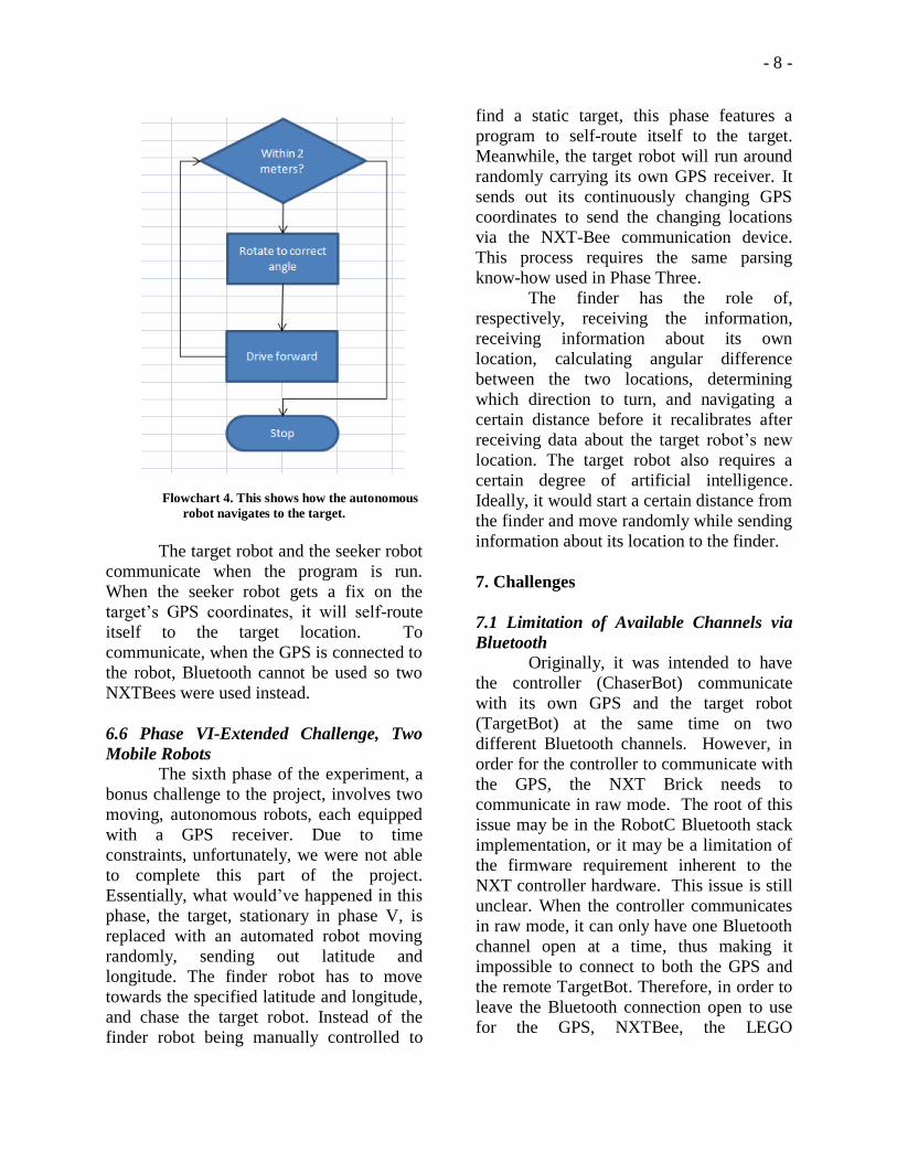
6.5 Phase V-Robot with Stationary Target
The fifth phase of the project
involves having the robot drive itself to a
stationary target robot mounted with its own
GPS transmitter. Therefore, all of the code
needs to be moved from the handheld
controller to the mobile seeker robot itself,
and the compass is positioned on the robot.
The compass needs to be mounted about
four to six inches from the motors, otherwise
the magnetic field from the motors would
affect the compass reading. At this point, the
code turns the robot in the correct direction,
then moves forward, constantly checking to
make sure that it is pointed the correct way.
If not, the robot will turn and correct itself
before moving until the robot is within two
meters of the target, at which point it stops,
as shown in Flowchart 4.
Function T1 T2 T3
Stop 0 0 0 Go Forward 1 0 1
Go Backward 0 1 0
Left Turn 1 0 0 Right Turn 0 0 1
Flowchart 3. Encoding the touch signals
- 8 -
Flowchart 4. This shows how the autonomous
robot navigates to the target.
The target robot and the seeker robot
communicate when the program is run.
When the seeker robot gets a fix on the
target’s GPS coordinates, it will self-route
itself to the target location. To
communicate, when the GPS is connected to
the robot, Bluetooth cannot be used so two
NXTBees were used instead.
6.6 Phase VI-Extended Challenge, Two
Mobile Robots
The sixth phase of the experiment, a
bonus challenge to the project, involves two
moving, autonomous robots, each equipped
with a GPS receiver. Due to time
constraints, unfortunately, we were not able
to complete this part of the project.
Essentially, what would’ve happened in this
phase, the target, stationary in phase V, is
replaced with an automated robot moving
randomly, sending out latitude and
longitude. The finder robot has to move
towards the specified latitude and longitude,
and chase the target robot. Instead of the
finder robot being manually controlled to
find a static target, this phase features a
program to self-route itself to the target.
Meanwhile, the target robot will run around
randomly carrying its own GPS receiver. It
sends out its continuously changing GPS
coordinates to send the changing locations
via the NXT-Bee communication device.
This process requires the same parsing
know-how used in Phase Three.
The finder has the role of,
respectively, receiving the information,
receiving information about its own
location, calculating angular difference
between the two locations, determining
which direction to turn, and navigating a
certain distance before it recalibrates after
receiving data about the target robot’s new
location. The target robot also requires a
certain degree of artificial intelligence.
Ideally, it would start a certain distance from
the finder and move randomly while sending
information about its location to the finder.
7. Challenges
7.1 Limitation of Available Channels via
Bluetooth
Originally, it was intended to have
the controller (ChaserBot) communicate
with its own GPS and the target robot
(TargetBot) at the same time on two
different Bluetooth channels. However, in
order for the controller to communicate with
the GPS, the NXT Brick needs to
communicate in raw mode. The root of this
issue may be in the RobotC Bluetooth stack
implementation, or it may be a limitation of
the firmware requirement inherent to the
NXT controller hardware. This issue is still
unclear. When the controller communicates
in raw mode, it can only have one Bluetooth
channel open at a time, thus making it
impossible to connect to both the GPS and
the remote TargetBot. Therefore, in order to
leave the Bluetooth connection open to use
for the GPS, NXTBee, the LEGO

- 9 -
Mindstorms’s version of the Digi XBee
radio device, was used. The NXTBee uses
XBee radios to wirelessly communicate and
allows connections to multiple channels.
Thus, the ChaserBot will collect coordinate
data from the GPS via Bluetooth while
another network channel is established with
the TargetBot. The TargetBot, in turn, will
have a similar infrastructure. It probes its
own coordinates from its own carried-on
GPS receiver and then broadcasts its
location via XBee network technology.
7.2 Lack of Testing Locations
Another problem that was faced over
the course of the project was with testing the
robot. Since the project relied heavily on
GPS measurements, the robot had to be
tested in areas where there was a strong GPS
signal. GPS signals are easily blocked or
altered by tall buildings or trees, or enclosed
spaces. Therefore, whenever the robot was
to be tested, it had to be outside in an open
field. This issue is common with all GPS
receivers, even the most advanced ones. In
addition, the choices for locations to test the
robot were limited by the terrain of the
location. In order for the robot to be able to
easily navigate around the area, the land had
to be flat. There could not be any ditches or
hills in the area. The presence of these
obstacles could tip the robot or set it off
course. The combination of these two
requirements severely limited the number of
places at which the robot could be
accurately tested.
7.3 Floating Point Calculations
While parsing the GPS data, there
were some problems. When the GPS sends
the information regarding its longitude and
latitude to the robot, it is in the form
DDMM.mmmm. Originally, the code tried
to have the NXT Brick work with the entire
string of numbers all together. There were
some problems with doing it this way. It
was discovered that in order for the robot to
understand these numbers, they need to be
separated into degrees, minutes, and
seconds. The problems that were present
were due to the fact that the NXT Brick
cannot simply use the entire number due to
the limitation in the number of bits that it
can handle. All computers have this
limitation, as they can only handle a certain
number of digits at a time for a single piece
of data. Therefore, the data had to be parsed
into separate integers. This process is
demonstrated by the pseudo-code below:
GPS measurement = 78.12345678
degree = GPS measurement as
an integer = 78
minute = GPS measurement –
degree * 60 = .12345678
* 60 = 7.40736, but you
only want the value 7
seconds = full minute value –
integer minute value *
60 = 7.40736 – 7 * 60 =
.40736 * 60 = 24.4416
This process will allow the NXT Brick to be
able to easily work with the GPS
measurements while maintaining a high
degree of precision and will allow the robot
to locate its target within an area of one
meter.
8. Future Improvements There are many ways that the project
can be improved in the future for smoother
performance. We faced limitations in
resources, which hindered us from testing
the more advanced limits of GPS-
autonomous robotics integration.
The language (RobotC) was easy to
learn, and the sensor compatibilities were
expansive. On the other hand, while the
basics of RobotC and the NXT brick were
easy to pick up, it is difficult to become fully intimate with all of their functions in the
limited time that was allotted for this
project. One suggestion for future research
is that researchers should either already have

- 10 -
a background in RobotC or be given more
time to learn its full capability.
The technology used was not up to
par with the accuracy the project required.
Since the robot operates on a small scale,
precision is required. Civilian GPS
technology has an error margin of at least 1
meter. The GPS receiver used in this project
is stated to have an error margin of around 3
meters. So, in order for the robot to find its
target more precisely, more advanced
technology would be needed.
Understandably, the technology required is
not necessarily in the budget for this project.
One way to improve the final results
would be to include obstacles between the
two mobile robots to make the experiment
more realistic. In this case, the robots must
use sensors, like the ultrasonic, to detect and
avoid obstacles while maintaining
navigation. However, this goal would
require a much longer time period to
achieve. It would require several months
and a more powerful platform to be able to
successfully avoid obstacles.
9. Real-World Implementations
For the military, integrating GPS
systems and autonomous robots can be
employed in the rising global warfare
between unmanned aerial vehicles (UAV)
and drones. In fact, drones have recently
become the primary vessel of combat in the
Middle East. Furthermore, by researching
and developing this technology, the military
can improve their search and rescue
operations to save soldiers’ lives. Research
is already being done in this area. For
example, every year the Defense Advanced
Research Project’s Agency hosts a
competition for automated vehicles called
the DARPA Grand Challenge. In 2012, the
agency has extended the requirements: the
vehicle must be driven by an autonomous
robot, which will navigate using GPS
technology to an unknown location. It will
then have to complete a series of tasks, such
as fixing a pipe and climbing a ladder [3].
As a follow up, by making use of the Global
Positioning System, robots would be able to
eventually navigate battle fields by them
selves and search secluded areas. This
would minimize the loss of human life in
search and rescue missions.
Also, the US military makes use of
Paladins, which shoot long-range GPS
guided missiles, such as Excaliburs.
However, Paladins are the size of and look
similar to tanks, but they are not as heavily
armored [12]. Although they are very useful
weapons, they and, by extension, their crews
can be very easily destroyed. By
implementing GPS navigation and the
autonomous robot technology, the Paladins
will be able to navigate without a crew and
minimize loss of human life.
Robots can also be sent to defuse
bombs or remove explosives. Planted
improvised explosive devices (IEDs),
otherwise known as roadside bombs, are
often detonated by insurgents when they see
a human or a vehicle. As robots are more
compact, they would be harder to notice.
Presently, the military makes use of
robots, such as the Talon IV MTRS. There
are four cameras mounted on the Talon, but
the conflicting views from these cameras
can make the navigation process
disorientating. Furthermore, as the robot
moves farther away from the control center,
the cameras start to lose connection and the
resulting static makes navigation difficult.
Also, training soldiers to be able to operate
these robots take time. As of now, soldiers
train using a video game simulation, for
example the Robotic Vehicle Trainer
developed by Picatinny Arsenal. As real as
these simulations are, they are not enough to
ensure that soldiers are fully prepared for the
reality that is war. Unprepared soldiers can
panic when they find themselves on a real
battlefield, which can lead to the failure of

- 11 -
the mission, or the destruction of the robot.
The games themselves take time and
funding to make. By making robots, which
can defuse bombs be able to navigate
themselves through the battle field,
essentially the military can cut out the
“middle-man,” saving time on training
soldiers and funding for creating games.
They would be easier to operate as well; for
example, on the Talon, the robot is not able
to move forward and move its gripping arm
at the same time due to the controller’s
restrictions.
Similarly, deep-sea retrievals where
manned navigation is impractical or unsafe
and unmanned aircrafts would benefit
greatly from autonomous robots aided by
GPS systems. As technology improves, and
unmanned aircrafts become more reliable,
they open a world of new information for
scientists. For example, an autonomous
aircraft would be able to operate in storm or
hazardous environments and collect data
without any risk to the pilot. This data can
be used to fight wildfires more effectively as
well as better understand the way the storms
work [6].
Furthermore, these robots could take
the place of human workers working in
nuclear or toxic environments. Radiation is
detrimental to human workers, but by
having robots clean up a contaminated site,
human lives do not have to be risked, and
the robots should come to no harm as they
have no cells, which can be affected by
radiation. These robots, though, would have
to be built with material that would resist
corrosion.
10. Conclusion The final result of this project is an
autonomous robot, made using the LEGO
Mindstorms kit and RobotC programming
language, that is capable of navigating to a
stationary target. Using GPS technology,
this robot can determine its current heading,
calculate the angle it needs to turn in order
to be facing the target, and move itself
accordingly until it reaches that
target. Further research into the integration
of autonomous robotics and GPS technology
has the potential to develop numerous new
militaristic and scientific technologies.
11. Acknowledgements
We would like to thank the Rutgers
University School of Engineering and the
New Jersey Governor’s School of
Engineering and Technology (GSET) for
giving us this opportunity. We are especially
grateful to Jean Patrick Antoine, the
Assistant Director of GSET, Dean Ilene
Rosen, Ed. D., the Director of GSET, and
the Governor’s School Board of Overseers.
Additionally, we would like to extend our
love to all of the resident advisors,
especially Adrien Perkins, our head
counseler, for the laughter they have
inspired and for the memories they have
gifted to us. We would like to take extra
time to thank Ashley So; not only was she
our resident advisor and friend, but she was
our project advisor, who walked alongside
us from start to finish.
This list would be incomplete
without the mention of Elizabeth Mabrey,
our brilliant mentor who shared with us her
passion and her inspiration and her assistant,
Nikhil Shah, whose continuing patience for
our infinite questions is a mystery we still
cannot figure out.
We would also like to extend our
gratitude towards the sponsors of the GSET
program: Morgan Stanley, Lockheed Martin,
South Jersey Industries, Inc, PSE&G, and,
of course, the State of New Jersey.
Finally, we would like to thank our
parents for giving us up for a month and
allowing us to attend GSET, even though
they must miss us terribly.

- 12 -
References
[1] "Basics." Bluetooth. Bluetooth SIG, Inc., n.d. Web. 10 July 2012.
<http://www.bluetooth.com/>.
[2] Driscoll, Ryan. "Advancements in GPS Technology." Construction Business Owner. Cahaba
Media Group, 2 Jan. 2012. Web. 11 July 2012.
<http://www.constructionbusinessowner.com/>.
[3] Drummond, Katie, and Noah Shachtman. "Darpa’s Next Grand Challenge: Build Us Lifelike,
Humanoid Robots." Wired. Conde Nast Digital, 05 Apr. 2012. Web. 12 July 2012.
<http://www.wired.com/>.
[4] "GPS History, Chronology, and Budgets." The Global Positioning System. 237-41. Print.
[5] "Latest Advancements in GPS Tracking Software." Tracking the World. N.p., n.d. Web. 12
July 2012. <http://www.trackingtheworld.com/>
[6]"NOAA Unmanned Aircraft Systems." NOAA Unmanned Aircraft Systems. N.p., n.d. Web. 19
July 2012. <http://uas.noaa.gov/>.
[7] "NXT Compass Sensor (NMC1034)." HiTechnic Products. Dataport Systems Inc., n.d. Web.
11 July 2012. <http://www.hitechnic.com/>.
[8] "President Turns Off GPS Selective Availability." About.com Geography. The New York
Times Company, 02 May 2000. Web. 14 July 2012. <http://geography.about.com/>.
[9] "Qstarz International Co., Ltd." Bluetooth GPS Receiver. N.p., n.d. Web. 10 July 2012.
<http://www.qstarz.com/>.
[10] "What Is NXT?" LEGO Mindstorms. The LEGO Group, n.d. Web. 11 July 2012.
<http://mindstorms.LEGO.com/>.
[11] "XBee Sensor for LEGO NXT Mindstorm | NXTBee from Dexter Industries." XBee Sensor
for LEGO NXT Mindstorm | NXTBee from Dexter Industries. N.p., n.d. Web. 20 July
2012. <http://www.dexterindustries.com/NXTBee1.html>.
[12] "XM982 Excalibur Precision Guided Extended Range Artillery Projectile." Global Security.
N.p., n.d. Web. 12 July 2012. <http://www.globalsecurity.org/>.