robot hand visual tracking using an adaptive fuzzy logic...
TRANSCRIPT

Robot hand visual tracking using an adaptive fuzzy logic controller
Carlos Pérez
Industrial System Engineering Department
Miguel Hernández University Avda. del Ferrocarril S/N Elche-Alicante (Spain)
Oscar Reinoso Industrial System Engineering
Department Miguel Hernández University
Avda. del Ferrocarril S/N Elche-Alicante (Spain)
M. Asunción Vicente Industrial System Engineering
Department Miguel Hernández University
Avda. del Ferrocarril S/N Elche-Alicante (Spain)
ABSTRACT This paper presents an algorithm to track an industrial robot hand during its movement. Based on acquired image and knowing the robot hand model, the pose is obtained. This information is used to move a pan-tilt camera and keep the robot hand centered in the image every time using an adaptive fuzzy logic controlled. This control law is used combined with a position prediction technique to improve the system behavior. Vision based systems have a lot of empirically adjustable parameters for a good working. With the algorithm proposed in this paper, the adjustable parameters are minimum, so the system robustness is increased.
Keywords Tracking, computer vision, fuzzy control, applications.
1. INTRODUCTION In this paper a visual tracking system of a robot hand is presented. The purpose is to track a robot hand by a vision system while the robot is making different tasks. We use a camera that can be controlled remotely (pan, tilt and zoom can be changed). Through the image acquired by the camera we can control the camera parameters taking into account that the robot hand will be always in the center of the image. To accomplish this process we can divide it in several steps. In a first step we must to estimate the pose of the robot hand studying the acquired image. In a second step and using the information stored about some previous positions, the next position is predicted to command the camera. In a third step, control action is calculated from the adaptive fuzzy controller and the camera is moved to track the object, in the fourth and final step, the adaptive parameters are calculated to be changed if its necessary.
Most of the available tracking techniques can be divided in two main classes: feature-based and model-based. Feature-based techniques are based on using geometric primitives (points, segments, circles, …), object contours, interesting regions, to track the object in the space [Mar00]. However, model-based techniques are based on the knowledge of the model to track the object. This model can be a CAD-model or a 2D representation. This option give a more robust solution for tracking (i.e., can run properly with partial object occlusion) [Bro00]. We have adopted the model-based scheme for this work. In this way in Section 2 we present the algorithm used to estimate the pose of the robot hand. To estimate the pose of the robot hand we must to calibrate the vision system to know the intrinsic parameters. In Section 3 we present the calibration method employed. In Section 4, the technique used to predict the position of the robot hand is explained. In Section 5, we present the adaptive fuzzy control law, core of this paper. In Section 6, the experimental results are presented and finally the Section 7 is for the conclusions. (see Section 8 for acknowledgement and section 9 for references).
2. POSE ESTIMATION The pose estimation algorithm obtain the pose of an object from a single image, based on a 3D target model. There are multiple procedures for object position and orientation estimation in a well-known
Permission to make digital or hard copies of all or part of this work for personal or classroom use is granted without fee provided that copies are not made or distributed for profit or commercial advantage and that copies bear this notice and the full citation on the first page. To copy otherwise, or republish, to post on servers or to redistribute to lists, requires prior specific permission and/or a fee.
WSCG POSTERS proceedings WSCG’2004, February 2-6, 2004, Plzen, Czech Republic. Copyright UNION Agency – Science Press
three-dimensional space geometry, modification of Lowe’s pose estimation algorithm, pose estimation using coplanar points, DeMenthon modification algorithm and pose estimation using quadrangular targets. We have used the DeMenthon algorithm [Dem01] to estimate the pose of the robot hand. This algorithm provides pose estimation obtained by a number of markers (significative points over the robot hand). So it is necessary to have several markers on it. Once these markers have been identified in the image we can estimate the pose of the robot hand taking into account the model and the real position of the markers in this hand. Several points have been chosen on the robot hand to use them as significative points (landmarks).
The DeMenthon algorithm requires to identify at least four non coplanar markers to estimate de pose of the object, that is named the “perspective four-point problem” or P4P.
Once the markers have been identified, coordinates of this points are introduced in the DeMenthon algorithm. This algorithm returns the rotation matrix and the translation vector that relate the camera coordinate system with robot hand coordinate system (pose). The accuracy of the estimated pose will depend on the relative distance between the markers identified. In our experiments we have concluded that the relative distance between the markers must be 10 cm or more for a good working.
3. VISION SYSTEM CALIBRATION While tracking process, the camera moves modifying its pan, tilt and zoom values. If zoom value is modified, calibration parameters are modified too. Usually, the algorithms of tracking do not modify the zoom of the camera during the tracking process. For this reason (zoom control), we need to know the parameters for all zoom values.
Two solutions can be adopted: calibration online during the tracking process or a pre-calibration off-
line. First one is rejected due to the high computational cost. Thus, pre-calibration off-line is selected. In order to know the parameters for all zoom values, we have chosen some points to make camera calibration. These points are distributed over all variable value range. A second order polinomial interpolation algorithm has been employed to estimate the calibration parameters between these points. In this way we have calibrate the system for 7 different camera zoom values. For each one of these points, 20 calibration images have been used.
4. POSITION PREDICTION We have selected an algorithm based on cubic spline for the position prediction due to the simplicity and the good results obtained in the simulation process. Recursive algorithms for position prediction are more efficient (lower computational cost) because they need less execution time, but the cubic spline computational cost is not significant compared with acquisition image time.
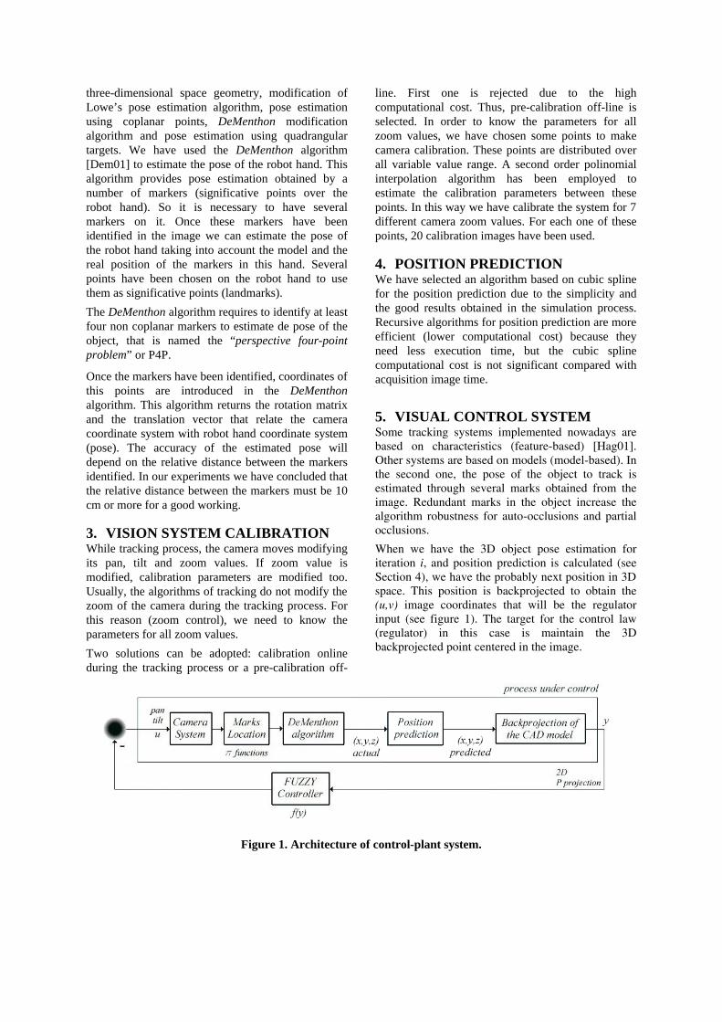
5. VISUAL CONTROL SYSTEM Some tracking systems implemented nowadays are based on characteristics (feature-based) [Hag01]. Other systems are based on models (model-based). In the second one, the pose of the object to track is estimated through several marks obtained from the image. Redundant marks in the object increase the algorithm robustness for auto-occlusions and partial occlusions.
When we have the 3D object pose estimation for iteration i, and position prediction is calculated (see Section 4), we have the probably next position in 3D space. This position is backprojected to obtain the (u,v) image coordinates that will be the regulator input (see figure 1). The target for the control law (regulator) in this case is maintain the 3D backprojected point centered in the image.
Figure 1. Architecture of control-plant system.

Figure 2. Membership generic functions for the FUZZY controller.
A complete knowledge of the equations model for this system would be very useful for a classic control regulator design, but in this case, with the pan-tilt camera used, it is very difficult to obtain the transfer function due to the non linearities and interne control laws implemented by SONY for pan and tilt movements. For this reason, it is difficult the classic regulator design to solve the control problem. Any research, assuming an approximated model system, propose the use of PID-PD adjustable regulators in function of the object velocity [Ele03]. Nevertheless, it is very easy to stablish several linguistic rules about the regulator behavior, so we have implemented a fuzzy logic regulator. We have designed a control scheme that use different regulators for each input of the system (pan, tilt and zoom value).
Next, we present the fuzzy algorithm developed for the control scheme shown in figure 2, that is based on four steps and introduce the variation of the limits α and β to make the gain adaptive (see figure 3). So, we will increase the non linearity of the control to adapt it better to the behavior of the camera in each section.
The steps executed by the algorithm are the following ones:
Step 1:
Suppose that the output y(t) takes values in the interval U=[α,β] ⊂ ℜ. Define 2N+1 fuzzy sets A1 in U that are normal, consistent and complete with the triangular membership functions shown in figure 4. That is, we use the N fuzzy sets A1, …, AN to cover the negative interval [α,0), the other N fuzzy sets AN+2, …, A2N+1 cover the positive interval (0,β], and
choose the center 1+Nx of fuzzy set AN+1 at zero.
Step 2:
Consider the 2N+1 fuzzy IF-THEN rules:
IF y is Al, THEN u is Bl
where l=1, 2, …, 2N+1, and the centers ly of fuzzy sets Bl are chosen such that
Step 3:
We have designed the fuzzy controller from the 2N+1 fuzzy IF-THEN rules specified using product inference engine, singleton fuzzifier, and center average defuzzifier; that is, the designed fuzzy controller is:
∑
∑+
=
+
=−=−= 12
1
12
1
)(
)()( N
lA
N
lA
l
y
yyyfu
l
l
µ
µ
(2)
where )(ylAµ are shown in figure 4 (each one
membership function) and ly satisfy the Step 2 conditions. Step 4:
An update process of fuzzy sets has been used based on the values obtained at previous moments or iterations. For it, last K output process values are stored. With these last K values, the maximum absolute value is calculated for each iteration. Calculated this maximum, the value of α and β are updated to: α=-β=max[K]. Next, the number of sets (N) is obtained ( N=f(β) ). The function f is defined as follows:
if round(β/c) > N1 N=round(β/c)
else if ceil(β/c)==N1 N=N1
else N=floor(β/c)
where N1 is the value of N in the previous iteration. The value of ‘c’ is empirically fixed depending on the number of rules that are desired to obtain. Also the ‘K’ value is empirically adjusted and it determines the smoothness of the camera movements. We have observed that too small ‘K’ values produce instability in the camera movement.
Step 5:
Back to step 1.
The adaptive actions introduced in step 4, allow the non saturation of the regulator control actions, reducing the instability and increasing the smoothness of the movement.
The proposed regulator is used for each one system input, that in this case are: pan, tilt and zoom, and they are empirically adjusted independently.
6. EXPERIMENTAL RESULTS The control system proposed in this paper and represented in figure 2 has been implemented on a 400MHz PC (see figure 4) with a Matrox Genesis board. The employed camera is a Sony EVID-31 (pan-tilt camera RS-232 controlled). The robot gripper has been designed by our research group. An RPC link between the robot controller and our PC for
++=≥+==
=≤
12,...,2010
,...,10
NNlforNlfor
Nlfory l

synchronization tasks and data taking has been implemented.
Figure 3. Image error (Y axis).
Figure 4. Target tracking.
Some experiments have been made to verify the system under control behavior. In this paper, we present an experiment in which the following error is null, as we can see in figure 3. The robot gripper moves at 15mm/s and is situated at 1,5 meters of the camera. The error grows mainly in the trajectory changes of the gripper, due to error introduced by the position predictor in initial iterations and to the regulator dynamic. In figure 4, we can see a trajectory change at t=23 seconds, so the following error is increased between t=23 and t=36 (see figure 3), during this 13 seconds, the predictor is working to anticipate the position and the fuzzy controller is changing the parameters to reduce the error. In figure 3, we can see that at t=36 the following error is almost null. This error is almost null up to t=54 because at this moment the gripper change its direction.
Figure 3 shows the following error in pixels and the noised response is due to the error in blobs position extraction that in our case is implemented with MIL (Matrox Image Library). The camera movement filter this noise and the image do not reproduce this vibration. The camera movement is smooth for the system user. The maximum following error (see figure 3) is about ±17 pixels. This guaranties that the robot hand will be always centered in the image and in any case always in the image frame.
At t=54, we can see at both figures (figure 3 and figure 4) that a change direction is produced by the autonomous system (robot). At this moment, the error is increased and reduced in about 13 seconds, the same time that in the previous change direction.
Figure 4 show the trajectory followed by the gripper (constant speed in x-axis) and the trajectory made by the camera during the process. The trajectory made by the robot hand is a perfect line and is partial occluded by the camera trajectory.
7. CONCLUSIONS In this paper, we present the object tracking system developed and applied on the industrial robot hand in movement. The goal of the system consist of keeping in the center of the acquired image the robot hand while it is moving controlling the pan tilt and zoom parameters of the camera (the zoom value is modified to maintain approximately constant the size of the robot hand). Once the pose of the robot hand has been estimated, a position predictor is used to know the probably next position, and this position is the input of the fuzzy controller developed for tracking implementation.
8. ACKNOWLEDGEMENT
This work has been supported by the “Comunidad Valenciana” Government through project RAMI (Robot Autónomo Móvil Inteligente) CTIDIA/2002/3.
9. REFERENCES [Dem01] Daniel F. DeMenthon and Larry S. Davis,
Model-Based Object Pose in 25 Lines of Code, University of Maryland, USA, 1992. Int. J. Comput. Vis., vol. 14, pp. 123-141, 1995.
[Hag01] Greg Hager. A Brief Reading Guide to Dynamic Vision January 4, 2001. http://www.cs.jhu.edu/~hager/tutorial/shortlist.pdf
[Mar00] Éric Marchand, Patrick Bouthemy, François Chaumette. A 2D-3D Model-Based Approach to Real-Time Visual Tracking. IRISA Publication Interne Nº1309 FRANCE, March 2000.
[Dem93] D.F. DeMenthon, Recognition and Tracking of 3D Objects by 1D Search, Proc. Image Understanding Workshop, Washington, DC, pp. 653-659, April 1993.
[Bro00] M. Brown, T. Drummond and R. Cipolla. 3D Model Acquisition by Tracking 2D Wireframes, Electronic Proceedings of The Eleventh British Machine Vision Conference University of Bristol. 11-14 September 2000.
[Ele03] Mainarda Elena, Mantovani Cristiano, Fabbri Damiano, Marcello Bonfé. Variable structure PID Controller for cooperative eye-in-hand/eye-to-hand Visual Servoing. Conference on Control Aplications CCA 2003. Istambul. Turkey. June 23-25.